M2 Quickstart Manual - V1.0 - Numark
M2 Quickstart Manual - V1.0 - Numark
M2 Quickstart Manual - V1.0 - Numark

Create successful ePaper yourself
Turn your PDF publications into a flip-book with our unique Google optimized e-Paper software.
10-INCH PROFESSIONAL DJ MIXER<br />
� QUICKSTART GUIDE<br />
ENGLISH ( 3 – 6 )<br />
� MANUAL DE INICIO RÁPIDO<br />
ESPAÑOL ( 7 – 10 )<br />
� GUIDE D’UTILISATION RAPIDE<br />
FRANÇAIS ( 11 – 14 )<br />
� MANUALE RAPIDO DI UTILIZZAZIONE<br />
ITALIANO ( 15 – 18 )<br />
� KURZANLEITUNG<br />
DEUTSCH ( 19 – 22 )
INTRODUCTION<br />
Welcome to the <strong>M2</strong> professional 2-channel mixer. Here are some of the features that you will come to love about<br />
your new <strong>M2</strong>:<br />
� 2 Line inputs for connecting CD players, samplers, or other line-level devices<br />
� 2 switchable Phono / Line inputs<br />
� 3-band EQ on each input channel<br />
� 1 microphone input with Gain and EQ controls<br />
� 1 headphone output with Cue Blend slider<br />
� Professional crosssfader with slope adjustment and reversible channel assignments<br />
� Master & Record outputs<br />
We hope that the <strong>M2</strong> serves you well for many years to come.<br />
Sincerely,<br />
The People of <strong>Numark</strong><br />
BOX CONTENTS<br />
� <strong>M2</strong><br />
� AC Power Adapter<br />
� <strong>Quickstart</strong> Guide<br />
� Safety & Warranty Information Booklet<br />
REGISTRATION<br />
Please go to http://www.numark.com to register your <strong>M2</strong>. Registering your product ensures that we can keep you<br />
up-to-date with any last-minute product developments and provide you with world-class technical support, should you<br />
run into any problems.<br />
GROUND RULES<br />
1. Make sure all items listed in the BOX CONTENTS section are included in the box.<br />
2. READ SAFETY & WARRANTY INFORMATION BOOKLET BEFORE USING THE PRODUCT.<br />
3. Study the connection diagram in this guide.<br />
4. Place mixer in an appropriate position for operation.<br />
5. Make sure all devices are turned off and all faders and gain knobs are set to “zero.”<br />
6. Connect all stereo input sources as indicated in the diagram.<br />
7. Connect the stereo outputs to power amplifier(s), tape decks, and/or other audio sources.<br />
8. Plug all devices into AC power.<br />
9. Switch everything on in the following order.<br />
• Audio input sources (i.e. turntables, CD players, etc.)<br />
• Mixer<br />
• Last, any amplifiers or output devices<br />
10. When turning off, always reverse this operation by,<br />
• Turning off amplifiers<br />
• Mixer<br />
• Last, any input devices<br />
3
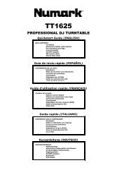
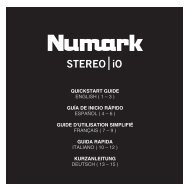
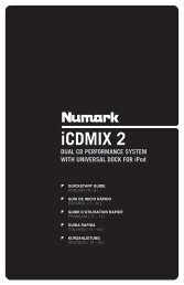
CONNECTION DIAGRAM<br />
CD<br />
PLAYER<br />
TURNTABLE CD<br />
PLAYER<br />
TURNTABLE<br />
HOUSE AMPLIFIFER OR<br />
SPEAKER SYSTEM<br />
Please Note: Channels 1 & 2 can accept line-level devices (i.e. CD players, samplers, line-level turntables) in the PHONO<br />
inputs, as long as the corresponding AUX LINE / PHONO switch is set to AUX LINE.<br />
4<br />
CD BURNER OR<br />
OTHER RECORDER<br />
MIC<br />
HEADPHONES
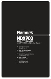
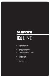
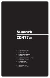
REAR PANEL FEATURES<br />
2<br />
1<br />
8 9 3 4 3 4<br />
5<br />
6 5 5<br />
1. AC IN – Use the included power adapter to connect the mixer to a power outlet. While the power is<br />
switched off, plug the power supply into the mixer first, then plug the power supply into a power outlet.<br />
Note: The mixer is designed to work with the included AC power supply only. Using an incompatible<br />
power supply could result in damage to the unit.<br />
2. POWER SWITCH – Turns the mixer on and off. Turn on the mixer after all input devices have been<br />
connected and before you turn on amplifiers. Turn off amplifiers before you turn off the mixer.<br />
3. LINE INPUTS (RCA) – Connect line-level devices, such as CD players, samplers or audio interfaces to<br />
these inputs.<br />
4. PHONO INPUTS (RCA) – Use standard RCA cables to connect your audio sources to these inputs.<br />
These inputs can accept both line and phono-level signals. (See #5 below.)<br />
5. AUX LINE / PHONO SWITCH – Flip this switch to the appropriate position, depending on the device<br />
connected to the PHONO inputs. If you are using phono-level turntables, set this switch to “PHONO” to<br />
provide the additional amplification needed for phono-level signals. If you are using a line-level device,<br />
such as a CD player or sampler, set this switch to “AUX LINE.”<br />
6. GROUNDING TERMINAL – If you are using phono-level turntables with a grounding wire, connect the<br />
grounding wire to these terminals. If you experience a low “hum” or “buzz”, this could mean that your<br />
turntables are not grounded.<br />
Note: Some turntables have a grounding wire built into the RCA connection and, therefore, nothing<br />
needs to be connected to the grounding terminal.<br />
7. MIC INPUT – Connect a ¼” microphone to this input. Microphone controls are located on the top<br />
panel.<br />
8. MASTER OUTPUT (RCA) – Use standard RCA cables to connect this output to a speaker or amplifier<br />
system. The level of this output is controlled by the MASTER knob on the top panel.<br />
9. RECORD OUTPUT (RCA) – Use standard RCA cables to connect this output to a recording device,<br />
such as a CD recorder or tape deck. The level of this output is based upon pre-master levels.<br />
7
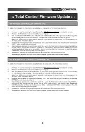
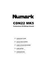
TOP & FRONT PANEL FEATURES<br />
1. POWER LED – Illuminates<br />
2.<br />
when the mixer is on.<br />
MIC GAIN – Adjusts the audio<br />
level of the microphone signal.<br />
4<br />
5 19<br />
5<br />
1<br />
3. MIC BASS – Adjusts the low<br />
(bass) frequencies of the<br />
3<br />
6<br />
6 13<br />
microphone channel.<br />
18<br />
4. MIC TREBLE – Adjusts the<br />
high (treble) frequencies of the<br />
microphone channel.<br />
2 7<br />
7 11<br />
Tip: If<br />
feedback<br />
you<br />
when<br />
experience<br />
using a<br />
8 17 8 14<br />
microphone at loud levels, try<br />
turning down the high (treble)<br />
frequencies.<br />
9<br />
16<br />
9<br />
5. CHANNEL GAIN – Adjusts<br />
the channel audio gain level,<br />
pre-fader and pre-EQ.<br />
6. CHANNEL TREBLE – Adjusts<br />
the high (treble) frequencies of<br />
the corresponding channel.<br />
10<br />
10<br />
7. CHANNEL MID – Adjusts the<br />
mid-range frequencies of the<br />
corresponding channel.<br />
8. CHANNEL BASS – Adjusts<br />
the low (bass) frequencies of<br />
the corresponding channel.<br />
15<br />
9. INPUT SELECTOR – Selects<br />
the input source to be routed<br />
to the corresponding channel. Input jacks are located on the rear panel.<br />
12<br />
10. CHANNEL FADER – Adjusts the audio level sent to the Program mix.<br />
11. CUE GAIN – Adjusts the audio level of the Cue channel in the headphones.<br />
12. HEADPHONES OUTPUT – Connect your ¼” headphones to this output for cueing and mix monitoring.<br />
Headphone output controls are located on the top panel.<br />
13. CUE MODE SELECTOR – Selects the audio to be routed to the headphones. Switch it to “MASTER”<br />
to hear the Program mix. Switch it to “CH1 CH2” to hear Channels 1 and 2 (see #14 above).<br />
14. CUE SLIDER – When CUE MODE SELECTOR is set on “CH1 - CH2” (see #13), the cue slider blends<br />
between Channel 1 & Channel 2 audio in the headphones. Move this slider to the left to hear Channel<br />
1, or to the right to hear Channel 2.<br />
15. CROSSFADER – Blends audio between Channels 1 and 2. Sliding the crossfader to the left plays<br />
Channel 1. Sliding it to the right plays Channel 2.<br />
Note: The crossfader is user-replaceable if it should ever wear out. Simply remove the facepanel, then<br />
remove the screws holding it in position. Replace the fader with a quality authorized replacement from<br />
your local <strong>Numark</strong> retailer only.<br />
16. CROSSFADER (CF) MODE – Press this button to reverse crossfader assignment of Channels 1 and 2.<br />
17. CROSSFADER (CF) SLOPE – Adjusts the slope of the crossfader curve. Flip switch to the left for a<br />
smooth fade (mixing) or to the right for a sharp cut (scratching).<br />
18. LEVEL INDICATORS – Monitors the audio level of the Program mix (L&R) and the pre-fader audio<br />
levels of Channels 1 and 2 (CUE).<br />
19. MASTER FADER – Adjusts the output volume of the Program mix.<br />
6
INTRODUCCIÓN<br />
Bienvenido al mezclador profesional de 2 canales <strong>M2</strong>. He aquí algunas de las características que seguramente<br />
disfrutará con su nuevo <strong>M2</strong>.<br />
� 2 entradas de línea para conectar reproductores de CD, muestreadores u otros dispositivos de nivel de línea<br />
� 2 entradas fonográficas/de línea conmutables<br />
� Ecualizador de 3 bandas en cada canal de entrada<br />
� 1 entrada de micrófono con controles de ganancia y tono<br />
� 1 salida para auriculares con cursor de combinación de cue<br />
� Crossfader profesional con ajuste de pendiente y asignaciones de canales reversibles<br />
� Salida maestra y para grabación<br />
Esperamos que el <strong>M2</strong> le brinde un buen servicio por muchos años.<br />
Atentamente,<br />
La Gente de <strong>Numark</strong><br />
CONTENIDO DE LA CAJA<br />
� <strong>M2</strong><br />
� Adaptador de CA<br />
� Guía de inicio rápido<br />
� Folleto de información sobre la seguridad y la garantía<br />
REGISTRO<br />
Visite http://www.numark.com y registre su <strong>M2</strong>. El registro de su producto asegura que podamos mantenerle<br />
actualizado con los desarrollos de productos de último momento y brindarle apoyo técnico de categoría mundial en<br />
caso de que tenga algún problema.<br />
REGLAS BÁSICAS<br />
1. Asegúrese de que todos los artículos indicados en “Contenido de la caja" estén incluidos en la caja.<br />
2. LEA EL FOLLETO DE INFORMACIÓN SOBRE LA SEGURIDAD Y LA GARANTÍA ANTES DE UTILIZAR EL<br />
PRODUCTO.<br />
3. Estudie el diagrama de conexión incluido en esta guía.<br />
4. Coloque el mezclador en una posición adecuada para su funcionamiento.<br />
5. Asegúrese que todos los dispositivos estén apagados y que todos los faders y perillas de ganancia estén en<br />
posición «cero».<br />
6. Conecte todas las fuentes de entrada estéreo como se indica en el diagrama.<br />
7. Conecte las salidas estéreo a los amplificadores de potencia, bandejas de cinta magnética y/o otras fuentes de<br />
audio.<br />
8. Enchufe todos los dispositivos al suministro de corriente alterna.<br />
9. Encienda todo en el siguiente orden:<br />
• fuentes de entrada de audio (por ejemplo, giradiscos, reproductores de CD, etc.)<br />
• el mezclador<br />
• por último, cualquier amplificador o dispositivo de salida<br />
10. Al apagar, realice siempre esta operación en sentido inverso:<br />
• apague los amplificadores<br />
• el mezclador<br />
• por último, cualquier dispositivo de entrada<br />
7
DIAGRAMA DE CONEXIÓN<br />
REPRODUCTOR<br />
DE CD<br />
GIRADISCOS REPRODUCTOR<br />
DE CD<br />
GIRADISCOS<br />
AMPLIFICADOR DE AUDITORIO<br />
O SISTEMA DE ALTAVOCES<br />
Para tener en cuenta: Los canales 1 y 2 pueden aceptar dispositivos de nivel de línea (por ej. reproductores de CD,<br />
muestreadores, giradiscos de nivel de línea) en las entradas PHONO, siempre que el conmutador AUX LINE / PHONO<br />
correspondiente esté colocado en AUX LINE.<br />
8<br />
QUEMADOR DE CD<br />
U OTRO<br />
GRABADOR<br />
MICRÓFONO<br />
AURICULARES
CARACTERÍSTICAS DEL PANEL TRASERO<br />
2<br />
1<br />
8 9 3 4 3 4<br />
9<br />
6 5 5<br />
1. ENTRADA DE CA - Use el adaptador de alimentación incluido para conectar el mezclador a un<br />
tomacorriente alimentado. Mientras está desconectada la alimentación eléctrica, enchufe la fuente de<br />
alimentación al mezclador primero, y luego al tomacorriente.<br />
Nota: El mezclador está diseñado para funcionar con la fuente de alimentación de CA incluida<br />
únicamente . Si usa una fuente de alimentación incompatible se puede dañar la unidad.<br />
2. INTERRUPTOR DE ENCENDIDO – Enciende y apaga el mezclador. Encienda el mezclador después<br />
de desconectar todos los dispositivos de entrada y antes de encender los amplificadores. Apague los<br />
amplificadores antes de apagar el mezclador.<br />
3. ENTRADAS DE LÍNEA (RCA) – Estas entradas se usan para conectar dispositivos de nivel de línea,<br />
tales como reproductores de CD, muestreadores o interfaces de audio.<br />
4. ENTRADAS DE FONOGRÁFICAS (RCA) – Use cables RCA estándar para conectar sus fuentes de<br />
audio a estas entradas. Estas entradas pueden aceptar señales de nivel de línea y fonográfico. (Vea<br />
el Nº 5 a continuación).<br />
5. INTERRUPTOR DE ENTRADA AUXILIAR DE LÍNEA | FONOGRÁFICA – Coloque este conmutador<br />
en la posición apropiada, en función del dispositivo conectado a las entradas PHONO. Si usa<br />
giradiscos de nivel fonográfico, coloque este conmutador en “PHONO” para proporcionar la<br />
amplificación adicional necesaria para las señales de este nivel. Si usa un dispositivo de nivel de<br />
línea, tal como un reproductor de CD o muestreador, coloque este conmutador en “AUX LINE”.<br />
6. TERMINAL DE TIERRA – Si usa giradiscos de nivel fonográfico con cable de conexión a tierra,<br />
conecte dicho cable a estos terminales. Si se experimenta un zumbido grave, puede significar que sus<br />
giradiscos no están conectados a tierra.<br />
Nota: Algunos giradiscos tienen el cable de conexión a tierra incorporado a la conexión RCA y, por lo<br />
tanto, no es necesario conectar nada al terminal de tierra.<br />
7. ENTRADA DE MICRÓFONO – Conecte un micrófono de 1/4” a esta entrada. Los controles de<br />
micrófono se encuentran en el panel superior.<br />
8. SALIDA MAESTRA (RCA) – Use cables RCA estándar para conectar esta salida a un sistema de<br />
altavoces o amplificador. El nivel de esta salida se controla con la perilla MASTER del panel superior.<br />
9. SALIDA PARA GRABACIÓN (RCA) – Use cables RCA estándar para conectar esta salida a un<br />
dispositivo de grabación, tal como un grabador de CD o bandeja de cinta. El nivel de esta salida se<br />
basa en los niveles pre-master.<br />
7
CARACTERÍSTICAS DE LOS PANELES SUPERIOR Y FRONTAL<br />
1. LED DE ENCENDIDO – Se<br />
ilumina cuando el mezclador<br />
está encendido.<br />
2. GANANCIA DE MICRÓFONO<br />
– Ajusta el nivel de audio de la<br />
señal de micrófono.<br />
3. GRAVES DE MICRÓFONO –<br />
Ajusta las bajas frecuencias<br />
(graves) del canal de<br />
micrófono.<br />
4. AGUDOS DE MICRÓFONO –<br />
Ajusta las altas frecuencias<br />
(agudos) del canal de<br />
micrófono.<br />
Consejo: Si experimenta<br />
realimentación cuando usa un<br />
micrófono con niveles altos,<br />
pruebe disminuyendo las altas<br />
frecuencias (agudos).<br />
5. GANANCIA DE CANAL –<br />
Ajusta el nivel de ganancia de<br />
audio, pre-fader y<br />
preecualización del canal.<br />
6. AGUDOS DE CANAL – Ajusta<br />
las altas frecuencias (agudos)<br />
del canal correspondiente.<br />
7. FRECUENCIAS MEDIAS DE<br />
CANAL – Ajusta las<br />
frecuencias medias del canal<br />
correspondiente.<br />
4<br />
3<br />
2<br />
8. GRAVES DE CANAL – Ajusta las bajas frecuencias (graves) de la señal del canal correspondiente.<br />
9. SELECTOR DE ENTRADAS – Permite seleccionar la fuente de entrada que se aplica al canal<br />
correspondiente. Los conectores de entrada se encuentran en el panel trasero.<br />
10. FADER DE CANAL – Ajusta el nivel de audio enviado a la mezcla del programa.<br />
11. GANANCIA DE CUE – Ajusta el nivel de la señal de audio del canal de cue en los auriculares.<br />
12. SALIDA PARA AURICULARES – Conecte sus auriculares de ¼” a esta salida para búsqueda de<br />
punto inicial (cue) y monitoreo de la mezcla. Los controles de la salida para auriculares se encuentran<br />
en el panel superior.<br />
13. SELECTOR DE MODO DE CUE – Selecciona el audio que se aplica a los auriculares. Conmútelo a<br />
“MASTER” para escuchar la mezcla de programa. Conmútelo a “CH1 CH2” para escuchar los canales<br />
1 y 2 (vea el Nº 14 más arriba).<br />
14. CURSOR DE CUE – Cuando el SELECTOR DE MODO DE CUE se coloca en “CH1 - CH2” (vea el Nº<br />
13), el cursor de cue combina el audio de los canales 1 y 2 en los auriculares. Mueva este cursos a la<br />
izquierda para oír el canal 1 o a la derecha para oír el canal 2.<br />
15. CROSSFADER – Combina el audio entre los canales 1 y 2. Si se desliza a la izquierda se reproduce<br />
el canal 1. Si se desliza a la derecha se reproduce el canal 2.<br />
Nota: El usuario puede reemplazar el crossfader en caso de que se desgaste. Simplemente, retire el<br />
panel frontal y luego los tornillos que lo mantienen sujeto. Cambie el fader por un repuesto de calidad<br />
autorizado por su vendedor de <strong>Numark</strong> más cercano.<br />
16. MODO DE CROSSFADER (CF) – Pulse este botón para revertir la asignación de crossfader de los<br />
canales 1 y 2.<br />
17. PENDIENTE DE CROSSFADER (CF) – Ajusta la pendiente de la curva del crossfader. Conmute el<br />
control a la izquierda para una fusión suave (mezcla) o a la derecha para un corte abrupto (rayado).<br />
18. INDICADORES DE NIVEL – Monitorean el nivel de audio de la mezcla de programa (izq y der) y los<br />
niveles de audio pre-fader de los canales 1 y 2 (CUE).<br />
19. FADER MAESTRO – Ajusta el volumen de salida de la mezcla de programa.<br />
10<br />
9<br />
5<br />
6<br />
7<br />
8<br />
10<br />
19<br />
18<br />
17<br />
15<br />
16<br />
5<br />
6<br />
7<br />
8<br />
10<br />
9<br />
1<br />
13<br />
11<br />
12<br />
14
INTRODUCTION<br />
Voici la console de mixage à 2 canaux <strong>M2</strong>. Voici quelques-unes des caractéristiques que vous apprécierez de la<br />
nouvelle console de mixage <strong>M2</strong> :<br />
� 2 entrées à niveau ligne permettent de brancher des lecteurs de disques compacts, échantillonneurs ou autres<br />
appareils à niveau ligne.<br />
� 2 entrées phono/ligne commutables.<br />
� Égalisation 3 bandes sur chaque canal d’entrée.<br />
� Entrée microphone avec commande de gain et de tonalité<br />
� Sortie casque d’écoute avec potentiomètre pour le mixage de la pré-écoute<br />
� Crossfader avec réglages d'intensité et assignation des canaux réversible<br />
� Sorties maître et d'enregistrement<br />
Nous espérons que la console de mixage <strong>M2</strong> vous servira bien pendant plusieurs années.<br />
Cordialement,<br />
Toute l’équipe de <strong>Numark</strong><br />
CONTENUE DE LA BOÎTE<br />
� <strong>M2</strong><br />
� Adaptateur CA<br />
� Guide d'utilisation simplifié<br />
� Le livret des consignes de sécurité et des informations concernant la garantie.<br />
ENREGISTREMENT<br />
Veuillez visiter le site internet http://www.numark.com pour enregistrer votre nouvelle console <strong>M2</strong>.L'enregistrement<br />
des produits vous permet d'être informé sur les toutes dernières nouveautés concernant les produits et de vous offrir<br />
un soutien technique de niveau international, si vous en aviez besoin.<br />
RÈGLES DE BASE<br />
1. Assurez-vous que tous les articles énumérés dans le contenu de la boîte de ce guide sont inclus dans la boîte.<br />
2. VEUILLEZ LIRE LE LIVRET DES CONSIGNES DE SÉCURITÉ ET DES INFORMATIONS SUR LA<br />
GARANTIE AVANT D'UTILISER LE PRODUIT.<br />
3. Examinez le schéma de connexion de ce guide.<br />
4. Placez la console de mixage en position de fonctionnement.<br />
5. Assurez-vous que tous les appareils sont hors tension et que tous les atténuateurs et le gain sont réglés à<br />
« zéro ».<br />
6. Connectez toutes les sources d'entrées stéréo tel qu'indiqué sur le schéma.<br />
7. Branchez toutes les sorties aux amplificateurs de puissance, aux lecteurs de cassette et aux sources audio.<br />
8. Branchez tous les appareils à une prise de courant alternatif (AC).<br />
9. Mettre tous les appareils sous tension dans l'ordre suivant.<br />
• sources d'entrée audio (c.-à-d.tourne-disques, lecteurs de disques compacts, etc.)<br />
• Consoles de mixage<br />
• en dernier, tous amplificateurs ou appareils de sortie<br />
10. Pour mettre hors tension, toujours inverser l'opération :<br />
• Éteindre les amplificateurs<br />
• Consoles de mixage<br />
• En dernier, tous les appareils d'entrée<br />
11
SCHÉMA DE CONNEXION<br />
TABLE<br />
LECTEUR CD LECTEUR CD<br />
TOURNANTE<br />
AMPLIFICATEUR OU SYSTÈME<br />
DE SONORISATION<br />
Veuillez noter : Les canaux 1 et 2 permettent de brancher des appareils à niveau ligne tels que lecteurs de disques<br />
compacts, échantillonneurs et tables tournantes pourvu que le commutateur AUX LINE/PHONO correspondant est en position<br />
AUX LINE.<br />
12<br />
TABLE<br />
TOURNANTE<br />
MICRO<br />
GRAVEUR CD OU<br />
AUTRE ENREGISTREUR<br />
CASQUE D'ÉCOUTE
CARACTÉRISTIQUES DU PANNEAU ARRIÈRE DU <strong>M2</strong><br />
2<br />
1<br />
8 9 3 4 3 4<br />
13<br />
6 5 5<br />
1. AC IN – Branchez l’adaptateur d’alimentation inclus pour brancher la console dans une prise<br />
d’alimentation murale. Lorsque la console de mixage est hors tension, branchez le câble d'alimentation<br />
dans la console, puis dans la prise de courant.<br />
Remarque : Cette console de mixage est conçue pour fonctionner avec le câble d'alimentation c. c.<br />
fourni uniquement. L’utilisation d’un autre câble pourrait endommager l’appareil.<br />
2. INTERRUPTEUR D'ALIMENTATION (POWER) – Met l’appareil sous et hors tension. Branchez la<br />
console après avoir branché tous les appareils et avant de mettre les amplificateurs sous tension.<br />
Mettre les amplificateurs hors tension avant de mettre la console de mixage hors tension.<br />
3. ENTRÉES LINE (RCA) – Ces entrées permettent de brancher des appareils à niveau ligne tels que<br />
lecteurs de disques compacts, échantillonneurs ou autres interfaces audio.<br />
4. ENTRÉES PHONO (RCA) – Branchez ces entrées aux sources audio à l’aide de câbles RCA<br />
standard. Ces entrées peuvent accepter les signaux phono et à niveau ligne. (Voir le nº 5 ci-dessous.)<br />
5. SÉLECTEUR AUX LINE | PHONO – Mettre ce sélecteur à la position appropriée, selon l’appareil<br />
branché aux entrées PHONO. Si vous utilisez des tables tournantes phono à niveau ligne, réglez ce<br />
sélecteur à « PHONO » afin d’ajouter plus d’amplification pour les signaux phono à niveau ligne. Pour<br />
brancher un appareil à niveau ligne, tel qu’un lecteur CD ou un échantillonneur, réglez le sélecteur à la<br />
position « AUX LINE ».<br />
6. BORNE DE MISE À LA TERRE – Si vous utilisez des tables tournantes avec fils de mise à la terre,<br />
assurez-vous de brancher le fils à cette borne. S’il y a un ronflement ou du bruit, il se pourrait que vos<br />
tables tournantes ne soient pas mises à la terre.<br />
Remarque : Certaines des tables tournantes fabriquées récemment sont dotées d'un fil de mise à la<br />
terre intégré à la connexion RCA, et donc, n'ont pas besoin d’être reliées à la borne de mise à la terre.<br />
7. ENTRÉE MIC – Permet de brancher un microphone ¼ po. Les commandes microphone sont situées<br />
sur le panneau supérieur.<br />
8. SORTIE MASTER (RCA) – Utilisez des câbles RCA standards afin de brancher cette sortie à un hautparleur<br />
ou à un système de sonorisation. Le niveau du signal de cette sortie est commandé par le<br />
bouton MASTER du panneau supérieur.<br />
9. SORTIE RECORD (RCA) – Utilisez des câbles RCA standards afin de brancher cette sortie à un<br />
appareil d’enregistrement tels qu’un lecteur de cassettes ou un graveur de CD. Le niveau de la sortie<br />
dépend des niveaux de pré-mastérisation.<br />
7
CARACTÉRISTIQUES DU PANNEAU SUPÉRIEUR ET AVANT<br />
1. DEL D’ALIMENTATION –<br />
2.<br />
S’allume lorsque la console de<br />
mixage est sous tension.<br />
MIC GAIN – Permet d'ajuster le<br />
4<br />
5 19<br />
5<br />
1<br />
niveau du signal audio de l’entrée<br />
microphone.<br />
3<br />
6<br />
6 13<br />
3. MIC BASS – Permet d'ajuster le<br />
niveau des basses fréquences du<br />
canal microphone.<br />
2 7<br />
18<br />
7 11<br />
4. MIC TREBLE – Permet d'ajuster<br />
le niveau des hautes fréquences<br />
du canal microphone.<br />
8 17 8 14<br />
Conseil : Si vous entendez du<br />
feedback lorsque vous utilisez le<br />
microphone à de hauts niveaux,<br />
essayez de diminuer les hautes<br />
fréquences.<br />
9<br />
16<br />
9<br />
5. CHANNEL GAIN – Permet<br />
6.<br />
d’ajuster le niveau du signal audio<br />
pré-atténuateur et pré-égalisation.<br />
CHANNEL TREBLE – Permet<br />
d'ajuster le niveau des hautes<br />
10<br />
10<br />
fréquences du canal<br />
7.<br />
correspondant.<br />
CHANNEL MID – Permet d'ajuster<br />
15<br />
le niveau des fréquences<br />
moyennes de l’audio du canal<br />
correspondant.<br />
12<br />
8. CHANNEL BASS – Permet<br />
9.<br />
d'ajuster le niveau des basses fréquences de l’audio du canal correspondant.<br />
SÉLECTEUR D’ENTRÉE – Ce réglage permet de sélectionner la source d’entrée qui est acheminée<br />
au canal correspondant. Les entrées sont situées sur le panneau arrière.<br />
10. POTENTIOMÈTRE DE CANAL – Permet d'ajuster le niveau de l’audio acheminé au programme en<br />
cours.<br />
11. CUE GAIN – Permet d’ajuster les niveaux du canal du casque d'écoute.<br />
12. SORTIE CASQUE D’ÉCOUTE – Permet de brancher un casque d’écoute ¼ po pour la pré-écoute et le<br />
mixage. Les commandes casque d’écoute sont situées sur le panneau supérieur.<br />
13. SÉLECTEUR CUE – Ce réglage permet de sélectionner la source d’entrée qui est acheminée au<br />
casque d’écoute. Positionnez-le sur « MASTER » afin d'écouter le programme en cours. Sélectionnez<br />
« CH1 CH2 » afin d’entendre les canaux 1 et 2. (Voir no. 14 ci-dessus)<br />
14. POTENTIOMÈTRE CUE – Lorsque le sélecteur de mode CUE est réglé sur « CH1 CH2 » (voir no.<br />
13), le potentiomètre permet de fondre l’audio du canal 1 et 2 envoyé au casque d'écoute. Déplacez<br />
le potentiomètre vers la gauche pour entendre l’audio du canal 1, ou vers la droite pour entendre celui<br />
du canal 2.<br />
15. CROSSFADER – Effectue un fondu entre les canaux 1 et 2. Lorsqu’il est déplacé vers la gauche, le<br />
canal 1 joue. Lorsqu’il est déplacé vers la droite, le canal 2 joue.<br />
Remarque : Ce potentiomètre est remplaçable par l’utilisateur s’il devait se détériorer. Retirez tout<br />
simplement le panneau avant et dévissez les vis qui le retiennent en position. Remplacez le<br />
potentiomètre avec un autre potentiomètre de qualité autorisé provenant de votre détaillant <strong>Numark</strong><br />
local.<br />
16. MODE CROSSFADER (CF) – Appuyez sur ce bouton afin d'inverser l'assignation des canaux 1 et 2.<br />
17. CROSSFADER (CF) SLOPE – Permet de régler l'intensité du fondu du potentiomètre. Tournez vers la<br />
droite pour un fondu progressif (mixage) ou tournez vers la gauche pour une coupure nette (scratch).<br />
18. INDICATEUR DE NIVEAU – Indique le niveau du programme en cours (G et D) et les niveaux préatténuation<br />
du canal 1 et 2 (CUE).<br />
19. POTENTIOMÈTRE MASTER – Permet d'ajuster le niveau du volume du programme en cours.<br />
14
INTRODUZIONE<br />
Benvenuti al mixer professionale a 2 canali <strong>M2</strong>. Ecco alcune delle nuove funzioni che adorerete del vostro nuovo <strong>M2</strong>:<br />
� 2 ingressi di linea per il collegamento di lettori CD, campionatori o altri dispositivi a livello di linea<br />
� 2 ingressi Phono / Linea commutabili<br />
� EQ a 3 bande su ciascun canale d’ingresso<br />
� 1 ingresso microfono con comandi Gain e Tone<br />
� 1 uscita cuffie con cursore Cue Blend<br />
� Crossfader professionale con regolazione di variazione e assegnazione reversibile di canale<br />
� Uscite Master & Record<br />
Ci auguriamo che l’<strong>M2</strong> vi accompagni con soddisfazione per molti anni a venire.<br />
Cordialmente,<br />
Il team <strong>Numark</strong><br />
CONTENUTI DELLA CONFEZIONE<br />
� <strong>M2</strong><br />
� Adattatore di alimentazione CA<br />
� Guida rapida<br />
� Libretto di istruzioni di sicurezza e garanzia<br />
REGISTRAZIONE<br />
Recarsi alla pagina http://www.numark.com per registrare l’<strong>M2</strong>. La registrazione del prodotto garantisce che possiamo<br />
tenervi aggiornati con tutti gli ultimissimi sviluppi del prodotto e offrirvi assistenza tecnica di livello mondiale, in caso di<br />
eventuali problemi.<br />
NORME FONDAMENTALI<br />
1. Assicurarsi che tutti gli elementi elencati nel paragrafo “Contenuti della confezione” siano contenuti nella<br />
confezione stessa.<br />
2. LEGGERE ATTENTAMENTE IL LIBRETTO DELLE ISTRUZIONI DI SICUREZZA E GARANZIA PRIMA DI<br />
UTILIZZARE IL PRODOTTO.<br />
3. Studiare con cura lo schema dei collegamenti fornito nella guida.<br />
4. Collocare il mixer in una posizione adeguata all’uso.<br />
5. Assicurarsi che tutti i dispositivi siano spenti e che tutti i fader e le manopole di guadagno siano impostati su<br />
“zero”.<br />
6. Collegare tutte le sorgenti di ingresso stereo come indicato nello schema.<br />
7. Collegare le uscite stereo ad amplificatori, mangianastri e/o altre sorgenti audio.<br />
8. Collegare tutti i dispositivi all’alimentazione CA.<br />
9. Accendere tutto nel seguente ordine:<br />
• sorgenti di ingresso audio (giradischi, lettori CD, ecc.)<br />
• il mixer<br />
• infine, eventuali amplificatori o dispositivi di uscita<br />
10. Al momento dello spegnimento, invertire questa operazione spegnendo:<br />
• gli amplificatori<br />
• il mixer<br />
• infine, qualsiasi dispositivo di ingresso<br />
15
SCHEMA DEI COLLEGAMENTI<br />
LETTORE CD<br />
GIRADISCHI LETTORE CD GIRADISCHI<br />
AMPLIFICATORE O IMPIANTO<br />
DI CASSE IN SALA<br />
Nota bene: i canali 1 e 2 sono in grado di accettare dispositivi a livello di linea (lettori CD, campionatori, giradischi a livello di<br />
linea) negli ingressi PHONO purché il corrispondente interruttore AUX LINE / PHONO sia su AUX LINE (linea).<br />
16<br />
MIC<br />
MASTERIZZATORE CD O<br />
ALTRO REGISTRATORE<br />
CUFFIE
CARATTERISTICHE PANNELLO POSTERIORE<br />
2<br />
1<br />
8 9 3 4 3 4<br />
17<br />
6 5 5<br />
1. AC IN – Servirsi dell’adattatore di alimentazione in dotazione per collegare il mixer ad una presa di<br />
alimentazione. Ad alimentazione spenta, collegare l’alimentazione elettrica innanzitutto nel mixer,<br />
quindi ad una presa elettrica.<br />
Nota bene: il mixer è concepito per funzionare unicamente con l’alimentatore CA in dotazione. L’uso di<br />
un alimentatore incompatibile può danneggiare l’apparecchio.<br />
2. INTERRUTTORE DI ALIMENTAZIONE (POWER) – Accende e spegne il mixer. Accendere il mixer<br />
dopo aver collegato tutti i dispositivi d’ingresso e prima di accendere gli amplificatori. Spegnere gli<br />
amplificatori prima di spegnere il mixer.<br />
3. INGRESSI DI LINEA (RCA) – Collegare dispositivi a livello di linea quali lettori CD, campionatori o<br />
interfacce audio a questi ingressi.<br />
4. INGRESSI PHONO (RCA) – Servirsi di cavi standard RCA per collegare sorgenti audio a questi<br />
ingressi. Questi ingressi sono in grado di accettare sia segnali a livello di linea che a livello phono.<br />
(Vedi n. 5 seguente.)<br />
5. INTERRUTTORE AUX LINEA | PHONO – Posizionare correttamente questo interruttore, a seconda<br />
del dispositivo collegato agli ingressi PHONO. Se si utilizzano giradischi a livello phono, impostare<br />
l’interruttore su “PHONO” per garantire l’amplificazione aggiuntiva necessaria per i segnali a livello<br />
phono. Se si utilizza un dispositivo a livello di linea quale un lettore CD o un campionatore, impostare<br />
l’interruttore su “AUX LINE” (linea).<br />
6. TERMINALE DI MESSA A TERRA – Se si utilizzano giradischi a livello phono dotati di cavo di messa<br />
a terra, questo va collegato a questi terminali. Se si verifica un “ronzio” o un “brusio” basso, ciò può<br />
significare che i giradischi non sono messi a terra.<br />
Nota bene: alcuni giradischi hanno il cavo di messa a terra incorporato nel collegamento RCA e, di<br />
conseguenza, non è necessario collegare nulla al terminale di messa a terra.<br />
7. INGRESSO MIC – Collegare un microfono da ¼” a questo ingresso. I comandi del microfono si trovano<br />
sul pannello superiore.<br />
8. USCITA MASTER (RCA) – Servirsi di cavi standard RCA per collegare questa uscita ad una cassa o<br />
ad un sistema di amplificatori. Il livello di questa uscita è controllato tramite la manopola MASTER sul<br />
pannello superiore.<br />
9. USCITA RECORD (RCA) – Servirsi di cavi standard RCA per collegare questa uscita ad un dispositivo<br />
di registrazione quale un registratore CD o una piastra di registrazione. Il livello di questa uscita è<br />
basato su livelli pre-master.<br />
7
CARATTERISTICHE PANNELLO SUPERIORE E ANTERIORE<br />
1. LED DI ALIMENTAZIONE –<br />
2.<br />
Si illumina quando il mixer è<br />
acceso.<br />
MIC GAIN (guadagno mic) –<br />
4<br />
5 19<br />
5<br />
1<br />
Regola il livello audio del<br />
3.<br />
segnale del microfono.<br />
MIC BASS (bassi mic) –<br />
Regola le frequenze basse<br />
(bass) del canale del<br />
microfono.<br />
3<br />
2<br />
6<br />
7<br />
18<br />
6<br />
7<br />
13<br />
11<br />
4. MIC TREBLE (acuti mic) –<br />
Regola le frequenze alte<br />
(treble) del canale del<br />
microfono.<br />
Suggerimento: in caso di<br />
ritorno durante l’uso di un<br />
8<br />
9<br />
17<br />
16<br />
8<br />
9<br />
14<br />
microfono ad alti livelli,<br />
provare ad abbassare le<br />
5.<br />
frequenze alte (treble).<br />
GAIN CANALE – Regola il<br />
livello di guadagno audio prefader<br />
e pre EQ del canale.<br />
10<br />
10<br />
6. CHANNEL TREBLE (acuti di<br />
canale) – Regola le frequenze<br />
alte (treble) del canale<br />
corrispondente.<br />
15<br />
7. CHANNEL MID (medi di<br />
canale) – Regola le frequenze<br />
medie del<br />
corrispondente.<br />
canale<br />
12<br />
8. CHANNEL BASS (bassi di<br />
canale) – Regola le frequenze basse (bass) del canale corrispondente.<br />
9. SELETTORE DI INGRESSI – Seleziona la sorgente di ingresso che verrà convogliata al canale<br />
corrispondente. I jack d’ingresso sono situati sul pannello posteriore.<br />
10. FADER CANALE – Regola il livello audio inviato al mix di programma (Program).<br />
11. GAIN CUE – Regola il livello audio del canale Cue nelle cuffie.<br />
12. USCITA CUFFIE – Collegare le cuffie da ¼” a questa uscita per il monitoraggio del mix e il cueing. I<br />
comandi dell’uscita cuffie si trovano sul pannello superiore.<br />
13. SELETTORE MODALITÀ CUE – Seleziona l’audio da convogliare alle cuffie. Commutarlo su<br />
“MASTER” per ascoltare il mix di Programma. Commutarlo su “CH1 CH2” per ascoltare i Canali 1 e 2<br />
(vedi n. 14 di cui sopra).<br />
14. CURSORE CUE – Quando il SELETTORE MODALITÀ CUE è impostato su “CH1 - CH2” (vedi n. 13), il<br />
cursore cue miscela tra l’audio del Canale 1 & Canale 2 in cuffia. Spostare questo cursore a sinistra<br />
per ascoltare il Canale 1 o verso destra per ascoltare il Canale 2.<br />
15. CROSSFADER – Miscela l’audio tra i Canali 1 e 2. Facendolo scorrere verso sinistra, viene riprodotto il<br />
Canale 1. Facendolo scorrere verso destra viene riprodotto il Canale 2.<br />
Nota bene: il crossfader è sostituibile dall’utente in caso di usura. Rimuovere il pannello anteriore e le<br />
viti che lo tengono in posizione. Sostituire il fader con un ricambio autorizzato acquistato presso il<br />
proprio rivenditore <strong>Numark</strong> locale.<br />
16. CROSSFADER (CF) MODE (modalità crossfader) – Premere questo tasto per invertire le assegnazioni<br />
dei Canali 1 e 2 al crossfader.<br />
17. CROSSFADER (CF) SLOPE (variazione crossfader) – Regola la variazione della curva del crossfader.<br />
Girare il comando verso sinistra per una dissolvenza uniforme (mix) oppure verso destra per un taglio<br />
netto (scratch).<br />
18. INDICATORI DI LIVELLO – Monitorano il livello audio del mix di Programma (sinistra e destra) e i livelli<br />
audio pre-fader dei Canali 1 e 2 (CUE).<br />
19. MASTER FADER – Regola il volume di uscita del mix di Programma.<br />
18
EINLEITUNG<br />
Herzlichen Glückwunsch zum Kauf des professionellen <strong>M2</strong> 2-Kanalmischpults. Hier einige Eigenschaften, die Sie an<br />
Ihrem <strong>M2</strong> zu schätzen lernen werden:<br />
� 2 Line-Eingänge, um CD-Spieler, Sampler oder andere Line-Levelgeräte anzuschließen<br />
� 2 umschaltbare Phono-/ Line-Eingänge<br />
� 3-Band EQ auf jedem Eingangskanal<br />
� 1 Mikrofoneingang mit Gain- und Tonsteuerung<br />
� 1 Kopfhörerausgang mit Cue-Blendregler<br />
� Professioneller Crossfader mit Neigungseinstellung und umgekehrter Kanalzuordnung<br />
� Master- & Aufnahmeausgänge<br />
Wir hoffen, dass Ihnen der <strong>M2</strong> über viele Jahre hinweg Freude bereitet.<br />
Hochachtungsvoll,<br />
Die Leute von <strong>Numark</strong><br />
INHALT DER VERPACKUNG<br />
� <strong>M2</strong><br />
� AC Netzteil<br />
� Kurzanleitung<br />
� Broschüre mit den Sicherheits- und Garantierichtlinien<br />
REGISTRIERUNG<br />
Registrieren Sie Ihren <strong>M2</strong> bitte auf http://www.numark.de. Dadurch geben Sie uns die Möglichkeit, Ihnen<br />
Informationen bei Produktaktualisierungen zukommen zu lassen und Ihnen bei möglichen Problemen den<br />
bestmöglichen technischen Support zu bieten.<br />
GRUNDREGELN<br />
Überprüfen Sie, dass sich alle auf der Vorderseite der Anleitung abgebildeten Bestandteile im Karton befinden.<br />
1. LESEN SIE VOR DER VERWENDUNG DES PRODUKTS DIE SICHERHEITSHINWEISE.<br />
2. Sehen Sie sich die Anschlussübersicht in dieser Anleitung an.<br />
3. Stellen Sie den Mixer in einer für den Betrieb geeigneten Position auf<br />
4. Achten Sie darauf, dass alle Geräte ausgeschaltet sind und dass alle Fader und Gain Regler Ihres Mixers auf<br />
dem niedrigsten Wert stehen.<br />
5. Verbinden Sie alle Stereo Eingangsquellen, wie in der Anschlussübersicht gezeigt, mit dem Mixer.<br />
6. Schließen Sie die Stereo Ausgänge an Verstärker, Kassettendecks oder andere Audiogeräte an.<br />
7. Schließen Sie alle Geräte an den Stromkreis an.<br />
8. Schalten Sie die Geräte in der folgenden Reihenfolge ein:<br />
• Audio Eingangsquellen (z.B. Turntables, CD Player, usw.)<br />
• Mixer<br />
• Zuletzt Verstärker und Ausgangsgeräte<br />
9. Schalten Sie Ihr System IMMER in genau der umgekehrten Reihenfolge aus, indem Sie:<br />
• Zuerst Verstärker<br />
• Dann den Mixer<br />
• Und am Schluss die Eingangsquellen ausschalten<br />
19
ANSCHLUSSDIAGRAMM<br />
CD-SPIELER PLATTENSPIELER CD-SPIELER PLATTENSPIELER<br />
VERSTÄRKER ODER<br />
LAUTSPRECHERSYSTEM<br />
Bitte beachten: An die Kanäle 1 & 2 können Line-Levelgeräte (z.B. CD-Spieler, Sampler, Line-Levelplattenspieler) über die<br />
PHONO-Eingänge angeschlossen werden, so lange der entsprechende AUX LINE / PHONO-Schalter auf AUX LINE steht.<br />
20<br />
CD-BRENNER<br />
ODER ANDERES<br />
AUFNAHMEGERÄT<br />
MIKROFON<br />
KOPFHÖRER
GERÄTERÜCKSEITE<br />
2<br />
1<br />
8 9 3 4 3 4<br />
21<br />
6 5 5<br />
1. NETZANSCHLUSS – Schließen Sie das Mischpult mit dem beigelegten Netzadapter an eine<br />
Steckdose an. Bei ausgeschaltetem Gerät zunächst das Netzkabel in das Mischpult, dann in die<br />
Steckdose stecken.<br />
Hinweis: Das Mischpult sollte nur mit dem beigelegten Wechselstromkabel betrieben werden. Der<br />
Gebrauch eines inkompatiblen Netzkabels könnte zur Beschädigung des Geräts führen.<br />
2. EIN-/AUSSCHALTER – Hier kann das Mischpult ein- und ausgeschaltet werden. Das Mischpult sollte<br />
dann eingeschaltet werden, sobald alle Eingabegeräte angeschlossen sind – erst dann die Verstärker<br />
einschalten. Die Verstärker sollten immer vor dem Mischpult ausgeschaltet werden.<br />
3. LINE-EINGÄNGE (RCA) – An diese Eingänge können Line-Levelgeräte wie CD-Spieler, Sampler oder<br />
Audiogeräte angeschlossen werden.<br />
4. PHONO-EINGÄNGE (RCA) – Sie können Ihre Audioquellen mit gebräuchlichen RCA-Kabeln an diese<br />
Eingänge anschließen. Diese Eingänge können sowohl für den Empfang von Line- als auch von<br />
Phono-Signalen verwendet werden. (Siehe Abschnitt 5 unten.)<br />
5. AUX-LINE-/ PHONOSCHALTER – Dieser Kippschalter sollte sich, entsprechend der an die jeweiligen<br />
PHONO-Eingänge angeschlossenen Geräte, in der richtigen Position befinden. Falls Phono-Level<br />
Plattenspieler verwendet werden, sollte der Schalter auf “PHONO” stehen, um die für Phono-<br />
Levelsignale notwendige, zusätzliche Verstärkung zu erzeugen. Falls Sie ein Line-Levelgerät wie<br />
einen CD-Spieler oder Sampler benutzen, stellen Sie den Schalter auf “AUX LINE.”<br />
6. ERDUNG – Falls Sie Phono-Level Plattenspieler mit einem Erdungskabel verwenden, schließen Sie<br />
das Erdungskabel an diese Anschlüsse an. Falls ein niedriges Brummen oder Summen auftritt, kann<br />
dies bedeuten, dass Ihre Plattenspieler nicht geerdet sind.<br />
Hinweis: Bei einigen Plattenspielermodellen ist das Erdungskabel in den RCA-Anschluss eingebaut, in<br />
diesen Fällen an die Erdung kein Kabel angeschlossen werden.<br />
7. MIKROFONEINGANG – Schließen Sie and diesen Eingang ein ¼”-Mikrofon an. Die Bedienelemente<br />
für das Mikrofon befinden sich auf der Geräteoberseite.<br />
8. MASTERAUSGANG (RCA) – Mit einem gebräuchlichen RCA-Kabel kann an diesen Ausgang ein<br />
Lautsprecher- oder Verstärkersystem angeschlossen werden. Die Lautstärke diese Ausgangs wird<br />
über den MASTER-Drehregler auf der Oberseite des Geräts gesteuert.<br />
9. AUFNAHMEAUSGANG (RCA) – Mit einem gebräuchlichen RCA-Kabel kann dieser Ausgang an ein<br />
Aufnahmegerät wie einen CD-Recorder oder ein Bandaufnahmegerät angeschlossen werden. Der<br />
Ausgabepegel ist von den Pre-Masterpegeln abhängig.<br />
7
GERÄTEOBER- & VORDERSEITE<br />
1. EIN/AUS LED – Leuchtet auf,<br />
2.<br />
wenn das Mischpult eingeschaltet<br />
ist.<br />
MIC-GAIN – Dient zur Einstellung<br />
4<br />
5 19<br />
5<br />
1<br />
des Audiopegels<br />
Mikrofonsignals.<br />
des<br />
3<br />
6<br />
6 13<br />
3. MIC-BÄSSE – Dient zur<br />
18<br />
Einstellung der Bassfrequenzen<br />
des Mikrofonkanals.<br />
2 7<br />
7 11<br />
4. MIC-HÖHEN – Dient zur<br />
Einstellung der Höhenfrequenzen<br />
des Mikrofonkanals.<br />
8 17 8 14<br />
Hinweis: Falls bei Verwendung<br />
des Mikrofons mit hoher Lautstärke<br />
Rückkopplung entsteht, verringern<br />
Sie die Hochfrequenzen, indem Sie<br />
diese herunterdrehen.<br />
9<br />
16<br />
9<br />
5. KANAL-GAIN – Dient zur<br />
Einstellung des Audio-Gain-Pegels,<br />
des Pre-Faders und des Pre-EQ.<br />
10<br />
10<br />
6. KANAL-HÖHEN – Dient zur<br />
Einstellung der Hochfrequenzen<br />
des jeweiligen Kanals.<br />
7. KANAL-MITTEN – Dient zur<br />
15<br />
Einstellung der Mittelfrequenzen<br />
des jeweiligen Kanals.<br />
8. KANAL-BÄSSE – Dient der<br />
12<br />
Einstellung der Bassfrequenzen<br />
9.<br />
des jeweiligen Kanals.<br />
EINGABEWAHL – Dient zur Auswahl der Eingabequelle, die an den jeweiligen Kanal weitergeleitet<br />
werden soll. Die Eingangsbuchsen befinden sich auf der Geräterückseite.<br />
10. KANAL-FADER – Dient zur Einstellung des Audiopegels des jeweiligen Kanals.<br />
11. CUE-LAUTSTÄRKE – Dient zur Einstellung des Kopfhörerlautstärkepegels.<br />
12. KOPFHÖRERAUSGANG – Schließen Sie Ihre –Kopfhörer für das Cueing und zum Abhören des Mixes<br />
hier an. Die Steuerelemente für die Kopfhörerausgabe befinden sich auf der Oberseite des Geräts.<br />
13. CUE-MODUSWAHL – Hier kann gewählt werden, welches Audiosignal zum Kopfhörer geschickt<br />
werden soll. Um den Programm-Mix zu hören, auf “MASTER” stellen. Wird auf “CH1 - CH2”<br />
geschaltet, werden dementsprechend die Kanäle 1 und 2 gehört (siehe Abschnitt 14 oben).<br />
14. CUE-SCHIEBEREGLER – Ist die CUE-MODUSAUSWAHL auf “CH1 - CH2” (siehe 13) geschaltet,<br />
überblendet der Cue-Schieberegler die Kanälen 1 & 2 im Kopfhörer. Wird der Schieberegler nach links<br />
bewegt, wird Kanal 1 gehört, bei Schieben nach rechts Kanal 2.<br />
15. CROSSFADER – Audioüberblendung zwischen den Kanälen 1 und 2. Wird der Crossfader nach links<br />
geschoben, wird Kanal 1 abgespielt. Bewegt man den Crossfader nach rechts, hört man Kanal 2.<br />
Hinweis: Der Crossfader kann im Falle von Abnutzung leicht vom Benutzer ausgewechselt werden.<br />
Dazu wird einfach die Abdeckung abgenommen, dann die Befestigungsschrauben des Faders<br />
entfernen. Der Fader sollte nur mit einem vom <strong>Numark</strong>-Fachhändler authorisierten Ersatzteil ersetzt<br />
werden.<br />
16. CROSSFADER (CF)-MODUS – Durch Drücken dieser Taste wird die Zuordnung des Crossfaders<br />
zwischen Kanal 1 und 2 geändert.<br />
17. CROSSFADER (CF)-NEIGUNG – Dient zur Einstellung des Neigungswinkels des Crossfaders. Für ein<br />
weiches Überblenden (Mixing) Schalter nach links stellen oder nach rechts für einen scharfen Schnitt<br />
(Scratching).<br />
18. PEGELANZEIGE – Dient zur Kontrolle des Audiopegels des Programm-Mix (L&R) sowie der Pre-<br />
Fader Audiopegel der Kanäle 1 und 2 (CUE).<br />
19. MASTER-FADER – Dient zur Einstellung der Lautstärke des Mixes.<br />
22
MANUAL VERSION 1.0
www.numark.com