Ejemplos de diagramas circuitales realizados con MAKECIRC
Ejemplos de diagramas circuitales realizados con MAKECIRC
Ejemplos de diagramas circuitales realizados con MAKECIRC

You also want an ePaper? Increase the reach of your titles
YUMPU automatically turns print PDFs into web optimized ePapers that Google loves.
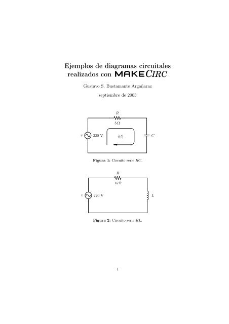
<strong>Ejemplos</strong> <strong>de</strong> <strong>diagramas</strong> <strong>circuitales</strong><br />
<strong>realizados</strong> <strong>con</strong> <strong>MAKECIRC</strong><br />
Gustavo S. Bustamante Argañaraz<br />
septiembre <strong>de</strong> 2003<br />
R<br />
5 Ω<br />
v<br />
220 V<br />
i(t)<br />
C<br />
Figura 1: Circuito serie RC.<br />
R<br />
15Ω<br />
v<br />
220 V<br />
L<br />
Figura 2: Circuito serie RL.<br />
1
<strong>Ejemplos</strong> <strong>de</strong> <strong>diagramas</strong> <strong>circuitales</strong> <strong>realizados</strong> <strong>con</strong> <strong>MAKECIRC</strong> 2<br />
R<br />
15Ω<br />
v<br />
220 V<br />
5 H<br />
L<br />
C<br />
12 pF<br />
Figura 3: Circuito serie RLC.<br />
v<br />
R L R C<br />
C<br />
Figura 4: Circuito RL y RC en paralelo.<br />
D r<br />
v<br />
Z L<br />
Figura 5: Circuito rectificador <strong>de</strong> media onda.<br />
Gustavo S. Bustamante Argañaraz
<strong>Ejemplos</strong> <strong>de</strong> <strong>diagramas</strong> <strong>circuitales</strong> <strong>realizados</strong> <strong>con</strong> <strong>MAKECIRC</strong> 3<br />
D 1<br />
v<br />
i(t)<br />
5 A<br />
220 V<br />
I cc<br />
300Ω<br />
Z L<br />
D 2<br />
Figura 6: Circuito rectificador <strong>de</strong> onda completa <strong>con</strong><br />
transformador <strong>con</strong> punto medio.<br />
D 4<br />
D 1<br />
v<br />
D 3<br />
D 2<br />
Z L<br />
Figura 7: Circuito rectificador <strong>de</strong> onda completa <strong>con</strong><br />
puente <strong>de</strong> diodos.<br />
1a<br />
R 1<br />
X L1<br />
X ′ L2<br />
R ′ 2<br />
2a<br />
0,82Ω<br />
0,92Ω<br />
0,9Ω<br />
0,8Ω<br />
V 1 G φ 0,41 2,24 B φ<br />
V ′<br />
2<br />
1b<br />
2b<br />
Figura 8: Circuito equivalente <strong>de</strong> un transformador.<br />
Gustavo S. Bustamante Argañaraz
<strong>Ejemplos</strong> <strong>de</strong> <strong>diagramas</strong> <strong>circuitales</strong> <strong>realizados</strong> <strong>con</strong> <strong>MAKECIRC</strong> 4<br />
I 1<br />
W<br />
A<br />
V<br />
Figura 9: Ensayo <strong>de</strong> cortocircuito <strong>de</strong> un transformador.<br />
V f<br />
I f I L<br />
I a<br />
R a<br />
R f<br />
E g<br />
G<br />
R L<br />
V L<br />
Figura 10: Cirtuito equivalente <strong>de</strong> un generador <strong>de</strong>rivación.<br />
R a<br />
R f<br />
E g<br />
G 500 V<br />
I a<br />
A I s<br />
I d<br />
54 A<br />
R L<br />
I<br />
R f s I<br />
B L<br />
R d<br />
Figura 11: Circuito equivalente <strong>de</strong> un generador compound<br />
en <strong>de</strong>rivación larga.<br />
Gustavo S. Bustamante Argañaraz
<strong>Ejemplos</strong> <strong>de</strong> <strong>diagramas</strong> <strong>circuitales</strong> <strong>realizados</strong> <strong>con</strong> <strong>MAKECIRC</strong> 5<br />
V a = V L = 120V<br />
I L I a<br />
I f<br />
0,25Ω R a<br />
R f<br />
M E c<br />
Figura 12: Circuito equivalente <strong>de</strong> un motor <strong>de</strong>rivación.<br />
0,2Ω<br />
R a<br />
V a<br />
E c<br />
M<br />
Figura 13: Circuito equivalente <strong>de</strong> un motor <strong>de</strong>rivación<br />
<strong>con</strong> resistencia <strong>de</strong> arranque regulable (reóstato <strong>de</strong><br />
arranque).<br />
I<br />
C C<br />
B<br />
I<br />
C B<br />
a R B E<br />
R C E 2<br />
E 1 I E<br />
V BB<br />
V CC<br />
Figura 14: Circuito <strong>de</strong> emisor común.<br />
Gustavo S. Bustamante Argañaraz
<strong>Ejemplos</strong> <strong>de</strong> <strong>diagramas</strong> <strong>circuitales</strong> <strong>realizados</strong> <strong>con</strong> <strong>MAKECIRC</strong> 6<br />
D r<br />
C e Z L<br />
v<br />
Figura 15: Circuito rectificador <strong>de</strong> media onda <strong>con</strong> filtro<br />
a <strong>con</strong><strong>de</strong>nsador.<br />
D 1<br />
v<br />
D 2<br />
C e Z L<br />
Figura 16: Circuito rectificador <strong>de</strong> onda completa <strong>con</strong><br />
filtro a <strong>con</strong><strong>de</strong>nsador.<br />
Z L<br />
Figura 17: Circuito rectificador <strong>de</strong> media onda polifásico.<br />
Gustavo S. Bustamante Argañaraz