DICROMAT + CR / DICROMAT 2+ CR
DICROMAT + CR / DICROMAT 2+ CR
DICROMAT + CR / DICROMAT 2+ CR

Create successful ePaper yourself
Turn your PDF publications into a flip-book with our unique Google optimized e-Paper software.
USER INSTRUCTIONS<br />
PROXIMITY SWITCHES<br />
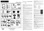
BOX CONTENTS. FIG.1<br />
1 - Power supply module.<br />
2 - Master sensor.<br />
3 - Extension cable of 50 cm for sensors.<br />
4 - Detection area delimiter.<br />
DES<strong>CR</strong>IPTION<br />
The <strong>DI<strong>CR</strong>OMAT</strong> + <strong>CR</strong> proximity switch detects the<br />
invisible infrared emissions coming from people and<br />
other heat sources without emitting any type of radiation.<br />
In the <strong>DI<strong>CR</strong>OMAT</strong> + <strong>CR</strong> several movement detection<br />
sensors (additional sensors) can be connected to a<br />
single power supply module.<br />
When a heat source moves under any sensor of the<br />
proximity switch, its output circuits are enabled, and<br />
when it stops detecting movement they are disabled<br />
after a delay time adjustable only in the master sensor.<br />
The <strong>DI<strong>CR</strong>OMAT</strong> + <strong>CR</strong> circuit, as well as circuit 1 of the<br />
<strong>DI<strong>CR</strong>OMAT</strong> <strong>2+</strong> <strong>CR</strong>, only react when the light conditions<br />
are below the level selected in the master sensor.<br />
Circuit 2 of the <strong>DI<strong>CR</strong>OMAT</strong> <strong>2+</strong> <strong>CR</strong> always reacts<br />
independently of the regulated brightness.<br />
The <strong>DI<strong>CR</strong>OMAT</strong> + <strong>CR</strong> is not suitable for alarm systems.<br />
INSTALLATION<br />
WARNING: The installation and assembly of electric<br />
appliances should be carried out by an authorized<br />
installer.<br />
The appliance is internally protected against interference<br />
by a safety circuit. Nevertheless, some particularly<br />
strong electromagnetic fields can manage to alter its<br />
operation, therefore it should not be mounted near<br />
inductive loads (motors, transformers, etc.).<br />
In the <strong>DI<strong>CR</strong>OMAT</strong> + <strong>CR</strong> installation it should be kept<br />
in mind that the detection takes place when crossing<br />
its detection beams, and therefore if the heat source to<br />
be detected is in parallel with the beams (not crossing<br />
them), it will detect it at a smaller distance, since it does<br />
not cross the beams until it is very near the sensor.<br />
In the FIG.2, the arrow indicates the direction the person<br />
or object to detect is moving in.<br />
The ambient temperature of the enclosure where the<br />
<strong>DI<strong>CR</strong>OMAT</strong> + <strong>CR</strong> is installed has a significant influence<br />
on the detection sensitivity and therefore on the detection<br />
distance. The sensitivity is less at higher temperatures<br />
since the appliance works with the movement of a heat<br />
source. The nearer the ambient temperature is to 36<br />
ºC (in most cases 36 ºC is the temperature of the human<br />
body), the worse is the detection.<br />
Fog or rain can impair the detection field. Clothing<br />
reduces the heat contribution to the enclosure and so<br />
diminishes the detection sensitivity.<br />
If two <strong>DI<strong>CR</strong>OMAT</strong>S + <strong>CR</strong> are connected in the same<br />
enclosure, the lamp powered by one of them should<br />
not be in the detection field of the other.<br />
ASSEMBLY<br />
Embedded in the ceiling, avoiding the presence of highly<br />
reflective surfaces (liquids), elements subject to abrupt<br />
changes in temperature (heating, air conditioning) or<br />
light sources and objects that can move with the wind<br />
(curtains, small trees, etc.) in its detection area.<br />
DISCONNECT THE VOLTAGE BEFORE BEGINNING<br />
INSTALLATION AND WIRING. RESTORE THE<br />
VOLTAGE WHEN THE DEVICE IS COMPLETELY<br />
INSTALLED.<br />
Drill a hole 65 mm in diameter. The thickness of the<br />
ceiling should be between 5 and 25 mm.<br />
Open the cover of the terminal housing of the power<br />
supply module.<br />
Connect the power supply and the load according to<br />
the FIG.3 diagrams.<br />
Check the connections made carefully.<br />
Close the cover of the terminal housing.<br />
Open the cover of the sensor terminal housing of the<br />
power supply module.<br />
Connect the <strong>DI<strong>CR</strong>OMAT</strong> + <strong>CR</strong> and <strong>DI<strong>CR</strong>OMAT</strong><br />
SENSOR + according to the FIG.4 diagrams.<br />
Close the cover of the sensor terminal housing of the<br />
power supply module.<br />
Introduce the power supply module through the hole<br />
drilled in the ceiling.<br />
Secure the sensor in the ceiling. Situate the legs on the<br />
inside of the ceiling hole. Press firmly until the sensor<br />
rim is flush with the ceiling.<br />
PUTTING INTO SERVICE. ADJUSTMENTS<br />
In the first connection or in prolonged power cuts, the<br />
device remains active for 30 seconds, after which it<br />
passes to normal operation.<br />
By rotating the sensor detector head (FIG.5) completely<br />
to one side, the “Time 1” (T1) and brightness (LUX)<br />
adjusting selectors are uncovered. By rotating to the<br />
opposite side, the distance adjusting selector (SENS)<br />
will appear, and in the <strong>DI<strong>CR</strong>OMAT</strong> <strong>2+</strong> <strong>CR</strong> version, the<br />
“Time 2” (T2) adjusting selector will appear.<br />
SETTING THE DETECTION FIELD<br />
To set the detection field, rotate SENS selector to the<br />
maximum position (7 m), LUX selector to the position<br />
“ ” and the T1 and T2 selectors to the minimum<br />
position.<br />
Move into the limits of the detection field to check the<br />
coverage. The limits of this field can be varied with<br />
SENS selector up to 7 metres in diameter with the<br />
device positioned at a height of 2.5 metres.<br />
The <strong>DI<strong>CR</strong>OMAT</strong> + <strong>CR</strong> is supplied with a detection area<br />
limiter divided into 12 sectors with two heights that can<br />
be trimmed. To exclude a sector of the field, cover the<br />
corresponding part of the lens with the limiter adapted<br />
to your needs. Each sector blocks an area of 30 degrees.<br />
The sensor head can tilt about one of its axes if it is<br />
desired to displace the detection area.<br />
DETECTION INDICATORS<br />
There is a red LED inside the sensors that lights when<br />
a detection is made. This LED can be used to assist<br />
in the adjustment of the detection field without needing<br />
to connect the load.<br />
SETTING THE BRIGHTNESS (only in master sensor)<br />
The <strong>DI<strong>CR</strong>OMAT</strong> + <strong>CR</strong> circuit, as well as circuit 1 of the<br />
<strong>DI<strong>CR</strong>OMAT</strong> <strong>2+</strong> <strong>CR</strong>, can be graduated to react only<br />
when the light conditions are below the level selected.<br />
By rotating LUX selector to the position " "<br />
they will react under any condition of brightness. By<br />
rotating to the position " " they only react in low<br />
brightness conditions. Circuit 2 (T1-T2) of the<br />
<strong>DI<strong>CR</strong>OMAT</strong> <strong>2+</strong> <strong>CR</strong> always reacts independently of the<br />
regulated brightness.<br />
SETTING THE DISCONNECTION DELAY (only in<br />
master sensor)<br />
By rotating the T1 and T2 selectors, the disconnection<br />
delay of the circuits is adjusted.<br />
TECHNICAL CHARACTERISTICS<br />
Power supply:<br />
Breaking power:<br />
Own<br />
consumption:<br />
Brightness<br />
range:<br />
Timing range:<br />
Detection angle:<br />
Detection field:<br />
Operating<br />
temperature:<br />
Type of<br />
protection:<br />
Protection class:<br />
230 V~ 50 Hz<br />
µ<br />
µ10 A 230 V~ Cos ϕ = 1<br />
<strong>DI<strong>CR</strong>OMAT</strong> + <strong>CR</strong>: 7 VA capacitive (1,1 W approx.)<br />
<strong>DI<strong>CR</strong>OMAT</strong> <strong>2+</strong> <strong>CR</strong>: 4,2 VA inductive (3,1 W approx.)<br />
2 - 2000 LUX<br />
Circuit 1 (L ): From 1 s. to 10 min.<br />
Circuit 2 ( T1-T2): From 10 s. to 15 min. (<strong>DI<strong>CR</strong>OMAT</strong> <strong>2+</strong> <strong>CR</strong>)<br />
360°<br />
Up to 7 m diameter at 2,5 m high<br />
From -10 °C to +45 °C<br />
IP20 as per EN 60529<br />
II as per EN 60335 in correct assembly<br />
conditions.<br />
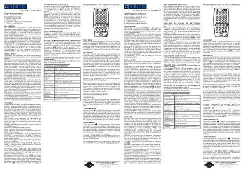
PROGRAMMING VIA REMOTE CONTROL<br />
TIME 1<br />
10'' 30'' 1'<br />
2' 3' 5' 10'<br />
TIME 2<br />
10'' 30'' 1' 2'<br />
3' 5' 10' 15'<br />
TEST MODE<br />
This is used to verify the detection field of each proximity<br />
switch by pressing the TEST button and moving to the<br />
detection field limits in order to check coverage. In this<br />
mode, the proximity switch detected independently of<br />
the light level. If not changed manually, the mode will<br />
automatically change AUTO mode after five minutes.<br />
AUTO MODE<br />
Proximity switch automatic mode operation is<br />
programmed by pressing the AUTO button on the <strong>CR</strong><br />
remote control and then selecting the time (TIME 1)<br />
during which the installation is to remain switched on.<br />
We can select between: pulses ( ) of one second<br />
ON and four seconds OFF, ten seconds, thirty seconds,<br />
one minute, two minutes, three minutes, five minutes<br />
and ten minutes. When used with two-circuit proximity<br />
detectors (TIME 2) is selected for the other circuit.<br />
Light level (LUX) is the light level value below which<br />
the proximity switch will detect is now selected from<br />
among the following values: 10 (only detects at night),<br />
100, 500 or 1000 Lux (it will detect in any light level<br />
situation, during the day and night).<br />
Sensitivity can be selected from the following values:<br />
Minimum, 50%, 75% or Maximum.<br />
These same parameters can be used to program the<br />
rest of the installation simply by positioning the remote<br />
control within range of each one and pressing the<br />
" " button so that they are programmed with the same<br />
parameters as previously set. This operation has to be<br />
repeated for each proximity switch.<br />
SPECIAL PROGRAMMING MODES<br />
- MODE 5H ON<br />
When the " ON 5H<br />
" button is pressed, the installation will<br />
remain switched on for five hours without interruption<br />
to allow cleaning and maintenance work to be performed<br />
etc. It will automatically return to AUTO mode after this<br />
time.<br />
- HOLIDAY MODE<br />
Holiday mode " " enables the installation to simulate<br />
one presence per day during long periods of absence.<br />
When this function is programmed, the proximity switch<br />
will turn the installation on for one hour when lighting<br />
conditions are those selected. After this time, it will then<br />
perform random switching during the next two hours<br />
for variable times between five and fifteen minutes.<br />
- ALARM MODE<br />
If this function " " is programmed, the proximity<br />
switch will turn on the installation with a sequence of<br />
fire alarm switching on and off lasting one second during<br />
thirty seconds when it detects any movement. During<br />
the last five seconds, it changes to a sequence switching<br />
on and off every 0.5 seconds.<br />
The LUX / SENS / TIME 1 and TIME 2 parameters can<br />
be changed in any function mode without having to<br />
change to AUTO mode<br />
For further information on programming, please read<br />
the instruction manual for the device to be configured.<br />
LUX<br />
10 100 500 1000<br />
S<br />
MIN 50% 75%<br />
AUTO<br />
5H<br />
ON<br />
TEST<br />
SENS<br />
S<br />
MAX<br />
ORBIS TECNOLOGÍA ELÉCTRICA S.A.<br />
Lérida, 61. E-28020 MADRID<br />
Tel.: + 34 91 567 22 77 Fax: + 34 91 571 40 06<br />
E-mail: info@orbis.es<br />
http://www.orbis.es<br />
INTERRUPTEUR DE PROXIMITÉ<br />
INSTRUCTIONS D'EMPLOI<br />
CONTENU DE LA BOÎTE. FIG.1<br />
1 - Module d'alimentation.<br />
2 - Capteur maître.<br />
3 - Câble de rallonge de 50 cm.<br />
4 - Limiteur de zone de détection.<br />
DES<strong>CR</strong>IPTION<br />
L'interrupteur de proximité <strong>DI<strong>CR</strong>OMAT</strong> + <strong>CR</strong> capte les<br />
émissions invisibles infrarouges provenant des<br />
personnes et d'autres sources de chaleur sans émettre<br />
aucun type de radiation.<br />
Le <strong>DI<strong>CR</strong>OMAT</strong> + <strong>CR</strong> permet de connecter plusieurs<br />
capteurs de détection de mouvement (capteurs<br />
supplémentaires), dans un seul module d'alimentation.<br />
Lorsqu'une source de chaleur bouge devant un capteur<br />
de l'interrupteur de proximité, ses circuits de sortie<br />
s'activent ; une fois qu'il cesse de capter le mouvement,<br />
ils se désactivent au bout d'un délai réglable uniquement<br />
dans le capteur maître.<br />
Le circuit du <strong>DI<strong>CR</strong>OMAT</strong> + <strong>CR</strong> ainsi que le circuit 1 du<br />
<strong>DI<strong>CR</strong>OMAT</strong> <strong>2+</strong> <strong>CR</strong> réagissent uniquement lorsque les<br />
conditions de lumière sont en-dessous du niveau<br />
sélectionné dans le capteur maître. Le circuit 2 du<br />
<strong>DI<strong>CR</strong>OMAT</strong> <strong>2+</strong> <strong>CR</strong> réagit toujours indépendamment<br />
de la luminosité réglée.<br />
Le <strong>DI<strong>CR</strong>OMAT</strong> + <strong>CR</strong> n'est pas adéquat pour les<br />
systèmes d'alarme.<br />
INSTALLATION<br />
ATTENTION: l'installation et le montage des appareils<br />
électriques doivent être réalisés par un installateur<br />
agréé.<br />
L'appareil est internement protégé contre les<br />
interférences par un circuit de sécurité. Toutefois,<br />
certains champs électromagnétiques particulièrement<br />
forts peuvent arriver à altérer son fonctionnement. Par<br />
conséquent, il ne doit pas être installé à proximité de<br />
charges inductives (moteurs, transformateurs, etc.).<br />
Lors de l'installation du <strong>DI<strong>CR</strong>OMAT</strong> + <strong>CR</strong>, il faut tenir<br />
compte du fait que la détection se produit lorsque l'on<br />
croise ses faisceaux de détection, et par conséquent<br />
si la source de chaleur à détecter avance parallèlement<br />
aux faisceaux (sans les traverser), la détection se<br />
produit à une plus faible distance, puisque qu'elle ne<br />
traverse pas les faisceaux, jusqu'à ce qu'elle n'arrive<br />
très près du capteur. Sur les figures FIG.2, la flèche<br />
indique la direction du mouvement de la personne ou<br />
objet à détecter.<br />
La température ambiante de l'enceinte où est installé<br />
le <strong>DI<strong>CR</strong>OMAT</strong> + <strong>CR</strong> a une assez grande influence sur<br />
la sensibilité de la détection et, par conséquent, sur la<br />
distance de détection. Plus la température est élevée,<br />
plus la sensibilité est faible, puisque l'appareil fonctionne<br />
par mouvement d'une source de chaleur Plus la<br />
température ambiante se rapproche de 36 ºC (dans la<br />
plupart des cas 36 ºC est la température du corps<br />
humain), plus la détection est faible.<br />
Le brouillard ou la pluie peuvent affecter négativement<br />
le champ de détection. Les vêtements chauds réduisent<br />
l'apport de chaleur à l'enceinte, diminuant par<br />
conséquent la sensibilité de détection.<br />
Si deux <strong>DI<strong>CR</strong>OMAT</strong> + <strong>CR</strong> sont connectés dans la même<br />
enceinte, la lampe actionnée par l'un des deux ne devra<br />
pas se trouver dans le champ de détection de l'autre.<br />
MONTAGE<br />
Encastré dans le toit, en évitant que dans sa zone de<br />
détection se trouvent des surfaces hautement<br />
réfléchissantes (liquides), des éléments sujets à de<br />
brusques changements de température (chauffage, air<br />
climatisé) ou des sources lumineuses et objets qui<br />
peuvent bouger avec le vent (rideaux, arbustes, etc.).<br />
DÉCONNECTEZ LA TENSION AVANT DE<br />
COMMENCER L'INSTALLATION ET LES<br />
CONNEXIONS. RÉTABLISSEZ LA TENSION<br />
LORSQUE LE DISPOSITIF EST TOTALEMENT<br />
INSTALLÉ.<br />
Réalisez un trou de 65 mm de diamètre. L'épaisseur<br />
du toit doit être comprise entre 5 et 25 mm.<br />
Ouvrez le couvercle du logement des bornes de<br />
connexion du module d'alimentation.<br />
Connectez l'alimentation et la charge selon les schémas<br />
du FIG.3.<br />
Vérifiez attentivement les connexions réalisées.<br />
Fermez le couvercle du logement des bornes de<br />
connexion.<br />
Ouvrez le couvercle du logement des connecteurs des<br />
capteurs du module d'alimentation.<br />
Connectez le <strong>DI<strong>CR</strong>OMAT</strong> + <strong>CR</strong> et les <strong>DI<strong>CR</strong>OMAT</strong><br />
SENSOR + selon les schémas du FIG.4.<br />
Fermez le couvercle du logement des connecteurs des<br />
capteurs du module d'alimentation.<br />
Introduisez par le trou du toit le module d'alimentation.<br />
Fixez le capteur dans le toit. Mettez les languettes à<br />
l'intérieur du trou du toit. Appuyez fortement jusqu'à ce<br />
que le bord du capteur s'ajuste avec le toit.<br />
MISE EN MARCHE. RÉGLAGES<br />
À la première connexion ou après des coupures<br />
d'alimentation prolongées, le dispositif reste 30 secondes<br />
activé, après quoi il passe à un fonctionnement normal.<br />
En tournant complètement d'un côté la tête de captage<br />
des capteurs (FIG.5), vous découvrez les sélecteurs<br />
de réglage de "Temps 1" (T1) et de luminosité (LUX).<br />
En tournant de l'autre côté, vous découvrez le sélecteur<br />
de réglage de distance (SENS) et, dans la version<br />
<strong>DI<strong>CR</strong>OMAT</strong> <strong>2+</strong> <strong>CR</strong>, le sélecteur de réglage de "Temps<br />
2" (T2).<br />
RÉGLAGE DU CHAMP DE DÉTECTION<br />
Pour régler el champ de détection, procédez comme<br />
suit :<br />
Pour régler el champ de détection, tournez le sélecteur<br />
SENS sur la position maximale (7 m), le sélecteur LUX<br />
sur la position " " et les sélecteurs T1 et T2 sur la<br />
position minimale.<br />
Déplacez-vous dans les limites du champ de détection<br />
pour vérifier la couverture. Les limites de ce champ<br />
peuvent être modifiées avec le sélecteur SENS jusqu'à<br />
7 mètres de diamètre, le dispositif étant placé à 2,5<br />
mètres de hauteur.<br />
Le <strong>DI<strong>CR</strong>OMAT</strong> + <strong>CR</strong> est livré avec un limiteur de la<br />
zone de détection divisé en 12 secteurs avec deux<br />
hauteurs qui peuvent être réglés selon les besoins.<br />
Pour exclure un secteur du champ, couvrez la partie<br />
correspondante de la lentille avec le limiteur adapté à<br />
vos besoins. Chaque secteur bloque une zone de 30º.<br />
La tête du capteur peut basculer sur un de ses axes si<br />
vous souhaitez déplacer la zone de détection.<br />
INDICATEURS DE DÉTECTION<br />
Il y a un voyant rouge à l'intérieur des capteurs qui<br />
s'allume quand la détection a lieu. Ce voyant peut être<br />
utilisé comme aide pour le réglage du champ de<br />
détection sans besoin de connecter la charge.<br />
RÉGLAGE DE LA LUMINOSITÉ (seulement dans le<br />
capteur maître)<br />
Le circuit du <strong>DI<strong>CR</strong>OMAT</strong> + <strong>CR</strong> ainsi que le circuit 1 du<br />
<strong>DI<strong>CR</strong>OMAT</strong> <strong>2+</strong> <strong>CR</strong> peuvent être gradués de façon à<br />
agir seulement lorsque les conditions de lumière sont<br />
en dessous du niveau sélectionné. En tournant le<br />
sélecteur LUX jusqu'à la position " " ils réagiront<br />
dans n'importe quelle condition de luminosité. En<br />
tournant jusqu'à la position " " ils ne réagiront que<br />
dans des conditions de luminosité faible. Le circuit 2<br />
(T1-T2) du <strong>DI<strong>CR</strong>OMAT</strong> <strong>2+</strong> <strong>CR</strong> réagit toujours<br />
indépendamment de la luminosité réglée.<br />
RÉGLAGE DU RETARD DE DÉCONNEXION<br />
(seulement dans le capteur maître)<br />
En tournant les sélecteurs T1 et T2, vous réglez le<br />
retard de la déconnexion des circuits.<br />
CARACTÉRISTIQUES TECHNIQUES<br />
Alimentation<br />
Pouvoir de rupture<br />
Consommation<br />
propre<br />
Intervalle de<br />
luminosité<br />
Intervalle de<br />
temporisation<br />
Angle de détection<br />
Champ de<br />
détection<br />
Température de<br />
fonctionnement<br />
Type de<br />
protection<br />
Classe de<br />
protection<br />
230 V~ 50 Hz<br />
µ<br />
µ10 A 230 V~ Cos ϕ = 1<br />
<strong>DI<strong>CR</strong>OMAT</strong> + <strong>CR</strong>: 7 VA capacitifs (1,1 W approx.)<br />
<strong>DI<strong>CR</strong>OMAT</strong> <strong>2+</strong> <strong>CR</strong>: 4,2 VA inductifs (3,1 W approx.)<br />
2 - 2000 LUX<br />
Circuit 1 (L ): De 1 s. à 10 min.<br />
Circuit 2 ( T1-T2): De 10 s. à 15 min. (<strong>DI<strong>CR</strong>OMAT</strong> <strong>2+</strong> <strong>CR</strong>)<br />
360°<br />
Jusqu'à 7 m de diamètre à 2,5 m de hauteur<br />
De -10 °C à +45 °C<br />
IP20 selon EN 60529<br />
II selon EN 60669 dans des conditions de<br />
montage correctes<br />
PROGRAMMER AVEC LA TÉLÉCOMMANDE<br />
TIME 1<br />
10'' 30'' 1'<br />
2' 3' 5' 10'<br />
TIME 2<br />
10'' 30'' 1' 2'<br />
3' 5' 10' 15'<br />
MODE TEST<br />
Il permet de vérifier le champ de détection de chaque<br />
interrupteur de proximité. Appuyez sur la touche<br />
TEST, puis déplacez-vous dans les limites du champ<br />
de détection pour vérifier la couverture. Dans ce mode,<br />
l'interrupteur de proximité fonctionne indépendamment<br />
de la luminosité. Si vous ne changez pas manuellement<br />
de mode, l'appareil passe au mode AUTO au bout de<br />
5 minutes.<br />
MODE AUTO<br />
Il permet de programmer le fonctionnement automatique<br />
de l'interrupteur de proximité. Appuyez sur la touche<br />
AUTO de la télécommande <strong>CR</strong>, puis sélectionnez le<br />
temps (TIME 1) pendant lequel vous souhaitez que<br />
votre installation reste allumée. Vous avez le choix entre<br />
(1 seconde ON et 4 secondes OFF), 10 secondes,<br />
30 secondes, 1 minute, 2 minutes, 3 minutes, 5 minutes<br />
et 10 minutes. Si vous disposez d'un détecteur de<br />
proximité à 2 circuits, sélectionnez le temps (TIME 2)<br />
pour l'autre circuit.<br />
Sélectionnez ensuite la luminosité (LUX) (valeur en<br />
dessous de laquelle l'interrupteur de proximité<br />
commencera la détection) en choisissant entre les<br />
valeurs suivantes: 10 (détection seulement la nuit), 100,<br />
500 ou 1000 Lux (détection dans toute situation de<br />
luminosité, tant de jour que de nuit).<br />
Pour programmer la sensibilité, vous pouvez choisir<br />
entre les valeurs suivantes : sensibilité minimale, 50<br />
%, 75 % ou sensibilité maximale.<br />
Si vous souhaitez programmer ces mêmes paramètres<br />
pour le reste de votre installation, il suffit de vous placer<br />
à la distance de portée de chaque appareil et d'appuyer<br />
sur la touche " " pour qu'il soit programmé avec les<br />
mêmes paramètres marqués antérieurement. Répétez<br />
la même opération pour chaque interrupteur de<br />
proximité.<br />
MODES SPÉCIAUX DE PROGRAMMATION<br />
- MODE 5H ON<br />
Lorsque vous appuyez sur la touche " ON 5H<br />
", l'installation<br />
restera allumée pendant 5 heures de suite pour<br />
permettre les tâches de nettoyage, de maintenance,<br />
etc. Une fois ce temps écoulé, l'appareil passe<br />
automatiquement au mode AUTO.<br />
- MODE VACANCES<br />
Le mode vacances " " permet à votre installation de<br />
simuler une présence journalière pendant de longues<br />
périodes d'absence. Lors de la programmation de cette<br />
fonction, l'interrupteur de proximité allumera l'installation<br />
pendant une heure lorsque les conditions de luminosité<br />
sont celles sélectionnées. Ensuite, il réalisera des<br />
allumages aléatoires pendant les deux heures suivantes<br />
avec des allumages variables compris entre 5 et 15<br />
minutes.<br />
- MODE ALARME<br />
Si vous programmez cette fonction " ", le détecteur<br />
de proximité allumera l'installation en cas de détection<br />
de mouvement avec une séquence d'alarme d'allumages<br />
et d'extinctions de 1 seconde de durée pendant 30<br />
secondes, et les 5 dernières secondes avec une<br />
séquence d'allumages et d'extinctions toutes les 0,5<br />
secondes.<br />
Les paramètres LUX / SENS / TIME 1 et TIME 2 peuvent<br />
être modifiés dans n'importe quel mode de fonction<br />
sans besoin de passer au mode AUTO.<br />
Pour en savoir plus sur la programmation, consultez le<br />
manuel d'instructions du dispositif à configurer.<br />
LUX<br />
10 100 500 1000<br />
S<br />
MIN 50% 75%<br />
AUTO<br />
5H<br />
ON<br />
TEST<br />
SENS<br />
S<br />
MAX<br />
ORBIS TECNOLOGÍA ELÉCTRICA S.A.<br />
Lérida, 61. E-28020 MADRID<br />
Tel.: + 34 91 567 22 77 Fax: + 34 91 571 40 06<br />
E-mail: info@orbis.es<br />
http://www.orbis.es