DICROMAT + CR / DICROMAT 2+ CR
DICROMAT + CR / DICROMAT 2+ CR
DICROMAT + CR / DICROMAT 2+ CR

You also want an ePaper? Increase the reach of your titles
YUMPU automatically turns print PDFs into web optimized ePapers that Google loves.
FIG.1<br />
FIG.2<br />
FIG.4<br />
2<br />
2.5 m.<br />
r<br />
<strong>DI<strong>CR</strong>OMAT</strong> + <strong>CR</strong><br />
A<br />
1x <strong>DI<strong>CR</strong>OMAT</strong>+ <strong>CR</strong> (A) + 4x <strong>DI<strong>CR</strong>OMAT</strong> SENSOR + (B)<br />
<strong>DI<strong>CR</strong>OMAT</strong> <strong>2+</strong> <strong>CR</strong><br />
B<br />
A<br />
1x <strong>DI<strong>CR</strong>OMAT</strong> <strong>2+</strong> <strong>CR</strong> (A) + 15x <strong>DI<strong>CR</strong>OMAT</strong> SENSOR + (B)<br />
A<br />
50 cm.<br />
B<br />
A<br />
50 cm.<br />
B<br />
B<br />
A<br />
B<br />
A<br />
B<br />
max. Ø7 m.<br />
<strong>DI<strong>CR</strong>OMAT</strong> + <strong>CR</strong><br />
A<br />
B<br />
a<br />
7 m.<br />
<strong>DI<strong>CR</strong>OMAT</strong> <strong>2+</strong> <strong>CR</strong><br />
A<br />
B<br />
7 m.<br />
121 38<br />
B<br />
B<br />
B<br />
B<br />
<strong>DI<strong>CR</strong>OMAT</strong><br />
SENSOR +<br />
B<br />
B<br />
<strong>DI<strong>CR</strong>OMAT</strong><br />
SENSOR +<br />
B<br />
B<br />
59.5<br />
1<br />
FIG.3<br />
B<br />
B<br />
B<br />
B<br />
L<br />
N<br />
<strong>DI<strong>CR</strong>OMAT</strong> + <strong>CR</strong> / <strong>DI<strong>CR</strong>OMAT</strong> <strong>2+</strong> <strong>CR</strong><br />
<strong>DI<strong>CR</strong>OMAT</strong><br />
SENSOR +<br />
B<br />
<strong>DI<strong>CR</strong>OMAT</strong><br />
SENSOR +<br />
B<br />
3<br />
L<br />
N<br />
FIG.5<br />
Ø63<br />
Ø65<br />
Ø80<br />
30''<br />
10''<br />
1' 2'<br />
3'<br />
10'<br />
5'<br />
N<br />
L<br />
N<br />
L<br />
T1<br />
T2<br />
L<br />
N<br />
L<br />
N<br />
4<br />
<strong>DI<strong>CR</strong>OMAT</strong> + <strong>CR</strong><br />
2200 W<br />
1200 W<br />
900 W<br />
1000 W<br />
5 - 25 mm<br />
A<br />
<strong>DI<strong>CR</strong>OMAT</strong> <strong>2+</strong> <strong>CR</strong><br />
1'<br />
30''<br />
10''<br />
C2<br />
C1<br />
2' 3'<br />
5'<br />
15'<br />
10'<br />
T1 T2 LUX SENS<br />
B<br />
A<br />
S<br />
2000 VA<br />
2200 W<br />
1000 W<br />
INTERRUPTOR DE PROXIMIDAD<br />
INSTRUCCIONES DE EMPLEO<br />
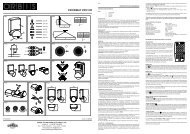
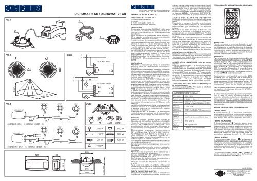
CONTENIDO DE LA CAJA. FIG.1<br />
1 - Módulo de alimentación.<br />
2 - Sensor.<br />
3 - Cable prolongador de 50 cm.<br />
4 - Limitador de área de detección.<br />
DES<strong>CR</strong>IPCIÓN<br />
El interruptor de proximidad <strong>DI<strong>CR</strong>OMAT</strong> + <strong>CR</strong> capta<br />
las emisiones invisibles infrarrojas procedentes de<br />
personas y otras fuentes de calor sin emitir ningún tipo<br />
de radiación.<br />
En un solo módulo de alimentación del <strong>DI<strong>CR</strong>OMAT</strong> +<br />
<strong>CR</strong> se le pueden conectar varios sensores de detección<br />
de movimiento (sensores adicionales).<br />
Cuando una fuente de calor se mueve bajo cualquiera<br />
de los sensores del interruptor de proximidad, sus<br />
circuitos de salida se activan. Una vez que deja de<br />
captar el movimiento se desactivan tras un tiempo de<br />
retardo regulable sólo en el sensor maestro.<br />
El circuito del <strong>DI<strong>CR</strong>OMAT</strong> + <strong>CR</strong> así como el circuito 1<br />
del <strong>DI<strong>CR</strong>OMAT</strong> <strong>2+</strong> <strong>CR</strong> reaccionan únicamente cuando<br />
las condiciones de luz están por debajo del nivel<br />
seleccionado en el sensor maestro. El circuito 2 del<br />
<strong>DI<strong>CR</strong>OMAT</strong> <strong>2+</strong> <strong>CR</strong> reacciona siempre<br />
independientemente de la luminosidad regulada.<br />
El <strong>DI<strong>CR</strong>OMAT</strong> + <strong>CR</strong> no es adecuado para sistemas de<br />
alarma.<br />
INSTALACIÓN<br />
ATENCIÓN: La instalación y el montaje de los aparatos<br />
eléctricos debe ser realizada por un instalador<br />
autorizado.<br />
El aparato está internamente protegido contra las<br />
interferencias por un circuito de seguridad. No obstante,<br />
algunos campos electromagnéticos especialmente<br />
fuertes pueden llegar a alterar su funcionamiento, por<br />
tanto, no debe instalarse próximo a cargas inductivas<br />
(motores, transformadores, etc.).<br />
En la instalación del <strong>DI<strong>CR</strong>OMAT</strong> + <strong>CR</strong> se debe tener<br />
en cuenta que la detección se produce al cruzar sus<br />
haces de detección, y que por tanto si la fuente de calor<br />
a detectar va en paralelo a los haces (no los atraviesa),<br />
la detectará a una menor distancia, ya que no cruza<br />
los haces hasta que está muy cerca del sensor. En la<br />
FIG.2, la flecha indica la dirección del movimiento de<br />
la persona u objeto a detectar.<br />
La temperatura ambiente del recinto donde se instala<br />
el <strong>DI<strong>CR</strong>OMAT</strong> + <strong>CR</strong> influye bastante en la sensibilidad<br />
de la detección y por tanto en la distancia de detección.<br />
A mayor temperatura peor sensibilidad, ya que el aparato<br />
funciona por movimiento de una fuente de calor. Cuanto<br />
más cercana sea la temperatura ambiente a la<br />
temperatura del cuerpo humano (36ºC) peor es la<br />
detección.<br />
La niebla o la lluvia pueden afectar negativamente al<br />
campo de detección. Las prendas de abrigo reducen<br />
el aporte de calor al recinto, disminuyendo por tanto la<br />
sensibilidad de detección.<br />
Si se conectan dos <strong>DI<strong>CR</strong>OMAT</strong> + <strong>CR</strong> en el mismo<br />
recinto, la lámpara accionada por uno de ellos no deberá<br />
encontrarse en el campo de detección del otro.<br />
MONTAJE<br />
Empotrado en techo, evitando que en su área de<br />
detección se encuentren superficies altamente<br />
reflectantes (líquidos), elementos sujetos a cambios<br />
bruscos de temperatura (calefacción, aire<br />
acondicionado) o fuentes luminosas y objetos que se<br />
puedan mover con el viento (cortinas, pequeños árboles,<br />
etc.).<br />
DESCONECTAR LA TENSIÓN ANTES DE INICIAR<br />
LA INSTALACIÓN Y LAS CONEXIONES.<br />
RESTABLECER LA TENSIÓN CUANDO EL<br />
DISPOSITIVO ESTÉ TOTALMENTE INSTALADO.<br />
Realizar un taladro con un diámetro de 65 mm. en un<br />
techo de espesor de entre 5 y 25 mm.<br />
Abrir la tapa del alojamiento de las bornas de conexiones<br />
del módulo de alimentación.<br />
Conectar la alimentación y la carga según los esquemas<br />
de la FIG.3.<br />
Compruebe cuidadosamente las conexiones realizadas.<br />
Cierre la tapa del alojamiento de las bornas de<br />
conexiones.<br />
Abrir la tapa del alojamiento de los conectores a<br />
sensores del módulo de alimentación.<br />
Conectar el <strong>DI<strong>CR</strong>OMAT</strong> + <strong>CR</strong> y el <strong>DI<strong>CR</strong>OMAT</strong> SENSOR<br />
+ según los esquemas de la FIG.4.<br />
Cierre la tapa del alojamiento de los conectores a<br />
sensores del módulo de alimentación.<br />
Introduzca el módulo de alimentación por el taladro en<br />
el techo.<br />
Fije el sensor en el techo colocando las patillas por el<br />
interior del agujero del techo. Presione fuertemente<br />
hasta que el borde del sensor esté ajustado al techo.<br />
PUESTA EN SERVICIO. AJUSTES<br />
En la primera conexión o en cortes de alimentación<br />
prolongados, el dispositivo permanece 30 segundos<br />
activado, tras los cuales pasa a funcionamiento normal.<br />
Girando completamente a un lado la cabeza captadora<br />
de los sensores (FIG.5), descubrimos los selectores de<br />
ajuste de "Tiempo 1" (T1) y de luminosidad (LUX).<br />
Girando al lado opuesto aparecerá el selector de ajuste<br />
de distancia (SENS), y en la versión <strong>DI<strong>CR</strong>OMAT</strong> <strong>2+</strong><br />
<strong>CR</strong>, aparecerá el selector de ajuste de "Tiempo 2" (T2).<br />
AJUSTE DEL CAMPO DE DETECCIÓN<br />
Para ajustar el campo de detección seguir los siguientes<br />
pasos:<br />
Para ajustar el campo de detección, gire el selector<br />
SENS a la posición máxima (7 m), el selector LUX a<br />
la posición " " y los selectores T1 y T2 a la posición<br />
mínima.<br />
Muévase en los límites del campo de detección para<br />
comprobar la cobertura. Los límites de este campo<br />
pueden variarse con el selector SENS hasta 7 metros<br />
de diámetro estando el dispositivo colocado a 2,5 metros<br />
de altura.<br />
El <strong>DI<strong>CR</strong>OMAT</strong> + <strong>CR</strong> se suministra con un limitador del<br />
área de detección dividido en 12 sectores con dos<br />
alturas que pueden ser recortados. Para excluir un<br />
sector del campo cubra la parte correspondiente de la<br />
lente con el limitador adaptado a sus necesidades.<br />
Cada sector bloquea un área de 30º.<br />
La cabeza del sensor puede bascular sobre uno de<br />
sus ejes si se desea desplazar el área de detección.<br />
INDICADORES DE DETECCIÓN<br />
Existe un led rojo en el interior de los sensores que se<br />
enciende cuando detecta. Este led puede ser utilizado<br />
como ayuda para el ajuste del campo de detección sin<br />
necesidad de conectar la carga.<br />
AJUSTE DE LA LUMINOSIDAD (sólo en sensor<br />
maestro)<br />
El circuito del <strong>DI<strong>CR</strong>OMAT</strong> + <strong>CR</strong> así como el circuito 1<br />
del <strong>DI<strong>CR</strong>OMAT</strong> <strong>2+</strong> <strong>CR</strong> pueden ser graduados de tal<br />
manera que actúen solamente cuando las condiciones<br />
de luz estén por debajo del nivel seleccionado. Girando<br />
el selector LUX hacia la posición " " reaccionarán<br />
en cualquier condición de luminosidad. Girando hacia<br />
la posición " " solamente reaccionarán en condiciones<br />
de baja luminosidad. El circuito 2 (T1-T2) del<br />
<strong>DI<strong>CR</strong>OMAT</strong> <strong>2+</strong> <strong>CR</strong> reacciona siempre<br />
independientemente de la luminosidad regulada.<br />
AJUSTE DEL RETARDO DE DESCONEXIÓN (sólo<br />
en sensor maestro)<br />
Girando los selectores T1 y T2 se ajusta el retardo de<br />
la desconexión de los circuitos.<br />
CARACTERÍSTICAS TÉCNICAS<br />
Alimentación:<br />
Poder de ruptura:<br />
Consumo propio:<br />
Rango de<br />
luminosidad:<br />
Rango de<br />
temporización:<br />
Ángulo de<br />
detección:<br />
Campo de<br />
detección:<br />
Temperatura de<br />
funcionamiento:<br />
Tipo de<br />
protección:<br />
Clase de<br />
protección:<br />
230 V~ 50 Hz<br />
µ<br />
µ10 A 230 V~ Cos ϕ = 1<br />
<strong>DI<strong>CR</strong>OMAT</strong> + <strong>CR</strong>: 7 VA capacitivos (1,1 W aprox.)<br />
<strong>DI<strong>CR</strong>OMAT</strong> <strong>2+</strong> <strong>CR</strong>: 4,2 VA inductivos (3,1 W aprox.)<br />
2 - 2000 LUX<br />
Circuito 1 (L ): De 1 s. a 10 min.<br />
Circuito 2 ( T1-T2): De 10 s. a 15 min. (<strong>DI<strong>CR</strong>OMAT</strong> <strong>2+</strong> <strong>CR</strong>)<br />
360°<br />
Hasta 7 m de diámetro a 2,5 m de altura<br />
-10 °C a +45 °C<br />
IP20 según EN 60529<br />
II según EN 60335 en condiciones<br />
de montaje correctas<br />
PROGRAMACIÓN MEDIANTE MANDO A DISTANCIA<br />
TIME 1<br />
10'' 30'' 1'<br />
2' 3' 5' 10'<br />
TIME 2<br />
10'' 30'' 1' 2'<br />
3' 5' 10' 15'<br />
MODO TEST<br />
Permite comprobar el campo de detección de cada<br />
interruptor de proximidad, pulsamos la tecla TEST y<br />
nos desplazamos en los límites del campo de detección<br />
para comprobar la cobertura. En este modo el interruptor<br />
de proximidad detecta independientemente de la<br />
luminosidad. Si no se cambia manualmente de modo,<br />
pasados 5 minutos pasa a modo AUTO.<br />
MODO AUTO<br />
Para programar el funcionamiento automático del<br />
interruptor de proximidad pulsamos la tecla AUTO del<br />
mando a distancia <strong>CR</strong> y a continuación seleccionamos<br />
el tiempo (TIME 1) que deseamos que permanezca<br />
encendida nuestra instalación. Podemos seleccionar<br />
entre: pulsos ( ) de 1 segundo ON y 4 segundos<br />
OFF, 10 segundos, 30 segundos, 1 minuto, 2 minutos,<br />
3 minutos, 5 minutos y 10 minutos. Si disponemos de<br />
un detector de proximidad de 2 circuitos seleccionamos<br />
el tiempo (TIME 2) para el otro circuito.<br />
Seleccionamos a continuación la Luminosidad (LUX),<br />
que es el valor por debajo del cual el interruptor de<br />
proximidad detectará. Pudiendo escoger entre los<br />
siguientes valores: 10 (solo detectará de noche), 100,<br />
500 ó 1000 Lux (detectará en cualquier situación de<br />
luminosidad, tanto de día como de noche).<br />
Para programar la Sensibilidad podemos escoger entre<br />
los valores: Sensibilidad Mínima, 50%, 75% o<br />
Sensibilidad Máxima.<br />
Si estos mismos parámetros queremos programarlos<br />
para el resto de nuestra instalación bastará con<br />
colocarse a la distancia de alcance de cada uno de<br />
ellos y pulsar la tecla " " para que quede programado<br />
con los mismos parámetros marcados anteriormente.<br />
Repetimos la misma operación para cada interruptor<br />
de proximidad.<br />
MODOS ESPECIALES DE PROGRAMACIÓN<br />
- MODO 5H ON<br />
Al pulsar la tecla " ON 5H<br />
" la instalación permanecerá<br />
encendida durante 5 horas ininterrumpidamente para<br />
permitir labores de limpieza, mantenimiento, etc. Pasado<br />
este tiempo pasa automáticamente a modo AUTO.<br />
- MODO VACACIONES<br />
El Modo Vacaciones " " permite que en largos<br />
periodos de ausencia nuestra instalación simule una<br />
presencia diaria. Al programar esta función el interruptor<br />
de proximidad encenderá la instalación durante una<br />
hora cuando las condiciones de luminosidad sean las<br />
seleccionadas, pasado este tiempo realizará encendidos<br />
aleatorios durante las dos siguientes horas con<br />
encendidos variables de entre 5 y 15 minutos.<br />
- MODO ALARMA<br />
Si programamos esta función " " el detector de<br />
proximidad encenderá la instalación al detectar cualquier<br />
movimiento con una secuencia de alarma de encendidos<br />
y apagados de 1 segundo de duración durante 30<br />
segundos, cambiando los últimos 5 segundos a una<br />
secuencia de encendidos y apagados cada 0,5<br />
segundos.<br />
Los parámetros de LUX, SENS, TIME 1 y TIME 2 se<br />
pueden cambiar en cualquier modo de función sin<br />
necesidad de cambiar a modo AUTO.<br />
LUX<br />
10 100 500 1000<br />
S<br />
MIN 50% 75%<br />
AUTO<br />
5H<br />
ON<br />
TEST<br />
SENS<br />
S<br />
MAX<br />
A016.13.55681<br />
ORBIS TECNOLOGÍA ELÉCTRICA S.A.<br />
Lérida, 61. E-28020 MADRID<br />
Tel.: + 34 91 567 22 77 Fax: + 34 91 571 40 06<br />
E-mail: info@orbis.es<br />
http://www.orbis.es
USER INSTRUCTIONS<br />
PROXIMITY SWITCHES<br />
BOX CONTENTS. FIG.1<br />
1 - Power supply module.<br />
2 - Master sensor.<br />
3 - Extension cable of 50 cm for sensors.<br />
4 - Detection area delimiter.<br />
DES<strong>CR</strong>IPTION<br />
The <strong>DI<strong>CR</strong>OMAT</strong> + <strong>CR</strong> proximity switch detects the<br />
invisible infrared emissions coming from people and<br />
other heat sources without emitting any type of radiation.<br />
In the <strong>DI<strong>CR</strong>OMAT</strong> + <strong>CR</strong> several movement detection<br />
sensors (additional sensors) can be connected to a<br />
single power supply module.<br />
When a heat source moves under any sensor of the<br />
proximity switch, its output circuits are enabled, and<br />
when it stops detecting movement they are disabled<br />
after a delay time adjustable only in the master sensor.<br />
The <strong>DI<strong>CR</strong>OMAT</strong> + <strong>CR</strong> circuit, as well as circuit 1 of the<br />
<strong>DI<strong>CR</strong>OMAT</strong> <strong>2+</strong> <strong>CR</strong>, only react when the light conditions<br />
are below the level selected in the master sensor.<br />
Circuit 2 of the <strong>DI<strong>CR</strong>OMAT</strong> <strong>2+</strong> <strong>CR</strong> always reacts<br />
independently of the regulated brightness.<br />
The <strong>DI<strong>CR</strong>OMAT</strong> + <strong>CR</strong> is not suitable for alarm systems.<br />
INSTALLATION<br />
WARNING: The installation and assembly of electric<br />
appliances should be carried out by an authorized<br />
installer.<br />
The appliance is internally protected against interference<br />
by a safety circuit. Nevertheless, some particularly<br />
strong electromagnetic fields can manage to alter its<br />
operation, therefore it should not be mounted near<br />
inductive loads (motors, transformers, etc.).<br />
In the <strong>DI<strong>CR</strong>OMAT</strong> + <strong>CR</strong> installation it should be kept<br />
in mind that the detection takes place when crossing<br />
its detection beams, and therefore if the heat source to<br />
be detected is in parallel with the beams (not crossing<br />
them), it will detect it at a smaller distance, since it does<br />
not cross the beams until it is very near the sensor.<br />
In the FIG.2, the arrow indicates the direction the person<br />
or object to detect is moving in.<br />
The ambient temperature of the enclosure where the<br />
<strong>DI<strong>CR</strong>OMAT</strong> + <strong>CR</strong> is installed has a significant influence<br />
on the detection sensitivity and therefore on the detection<br />
distance. The sensitivity is less at higher temperatures<br />
since the appliance works with the movement of a heat<br />
source. The nearer the ambient temperature is to 36<br />
ºC (in most cases 36 ºC is the temperature of the human<br />
body), the worse is the detection.<br />
Fog or rain can impair the detection field. Clothing<br />
reduces the heat contribution to the enclosure and so<br />
diminishes the detection sensitivity.<br />
If two <strong>DI<strong>CR</strong>OMAT</strong>S + <strong>CR</strong> are connected in the same<br />
enclosure, the lamp powered by one of them should<br />
not be in the detection field of the other.<br />
ASSEMBLY<br />
Embedded in the ceiling, avoiding the presence of highly<br />
reflective surfaces (liquids), elements subject to abrupt<br />
changes in temperature (heating, air conditioning) or<br />
light sources and objects that can move with the wind<br />
(curtains, small trees, etc.) in its detection area.<br />
DISCONNECT THE VOLTAGE BEFORE BEGINNING<br />
INSTALLATION AND WIRING. RESTORE THE<br />
VOLTAGE WHEN THE DEVICE IS COMPLETELY<br />
INSTALLED.<br />
Drill a hole 65 mm in diameter. The thickness of the<br />
ceiling should be between 5 and 25 mm.<br />
Open the cover of the terminal housing of the power<br />
supply module.<br />
Connect the power supply and the load according to<br />
the FIG.3 diagrams.<br />
Check the connections made carefully.<br />
Close the cover of the terminal housing.<br />
Open the cover of the sensor terminal housing of the<br />
power supply module.<br />
Connect the <strong>DI<strong>CR</strong>OMAT</strong> + <strong>CR</strong> and <strong>DI<strong>CR</strong>OMAT</strong><br />
SENSOR + according to the FIG.4 diagrams.<br />
Close the cover of the sensor terminal housing of the<br />
power supply module.<br />
Introduce the power supply module through the hole<br />
drilled in the ceiling.<br />
Secure the sensor in the ceiling. Situate the legs on the<br />
inside of the ceiling hole. Press firmly until the sensor<br />
rim is flush with the ceiling.<br />
PUTTING INTO SERVICE. ADJUSTMENTS<br />
In the first connection or in prolonged power cuts, the<br />
device remains active for 30 seconds, after which it<br />
passes to normal operation.<br />
By rotating the sensor detector head (FIG.5) completely<br />
to one side, the “Time 1” (T1) and brightness (LUX)<br />
adjusting selectors are uncovered. By rotating to the<br />
opposite side, the distance adjusting selector (SENS)<br />
will appear, and in the <strong>DI<strong>CR</strong>OMAT</strong> <strong>2+</strong> <strong>CR</strong> version, the<br />
“Time 2” (T2) adjusting selector will appear.<br />
SETTING THE DETECTION FIELD<br />
To set the detection field, rotate SENS selector to the<br />
maximum position (7 m), LUX selector to the position<br />
“ ” and the T1 and T2 selectors to the minimum<br />
position.<br />
Move into the limits of the detection field to check the<br />
coverage. The limits of this field can be varied with<br />
SENS selector up to 7 metres in diameter with the<br />
device positioned at a height of 2.5 metres.<br />
The <strong>DI<strong>CR</strong>OMAT</strong> + <strong>CR</strong> is supplied with a detection area<br />
limiter divided into 12 sectors with two heights that can<br />
be trimmed. To exclude a sector of the field, cover the<br />
corresponding part of the lens with the limiter adapted<br />
to your needs. Each sector blocks an area of 30 degrees.<br />
The sensor head can tilt about one of its axes if it is<br />
desired to displace the detection area.<br />
DETECTION INDICATORS<br />
There is a red LED inside the sensors that lights when<br />
a detection is made. This LED can be used to assist<br />
in the adjustment of the detection field without needing<br />
to connect the load.<br />
SETTING THE BRIGHTNESS (only in master sensor)<br />
The <strong>DI<strong>CR</strong>OMAT</strong> + <strong>CR</strong> circuit, as well as circuit 1 of the<br />
<strong>DI<strong>CR</strong>OMAT</strong> <strong>2+</strong> <strong>CR</strong>, can be graduated to react only<br />
when the light conditions are below the level selected.<br />
By rotating LUX selector to the position " "<br />
they will react under any condition of brightness. By<br />
rotating to the position " " they only react in low<br />
brightness conditions. Circuit 2 (T1-T2) of the<br />
<strong>DI<strong>CR</strong>OMAT</strong> <strong>2+</strong> <strong>CR</strong> always reacts independently of the<br />
regulated brightness.<br />
SETTING THE DISCONNECTION DELAY (only in<br />
master sensor)<br />
By rotating the T1 and T2 selectors, the disconnection<br />
delay of the circuits is adjusted.<br />
TECHNICAL CHARACTERISTICS<br />
Power supply:<br />
Breaking power:<br />
Own<br />
consumption:<br />
Brightness<br />
range:<br />
Timing range:<br />
Detection angle:<br />
Detection field:<br />
Operating<br />
temperature:<br />
Type of<br />
protection:<br />
Protection class:<br />
230 V~ 50 Hz<br />
µ<br />
µ10 A 230 V~ Cos ϕ = 1<br />
<strong>DI<strong>CR</strong>OMAT</strong> + <strong>CR</strong>: 7 VA capacitive (1,1 W approx.)<br />
<strong>DI<strong>CR</strong>OMAT</strong> <strong>2+</strong> <strong>CR</strong>: 4,2 VA inductive (3,1 W approx.)<br />
2 - 2000 LUX<br />
Circuit 1 (L ): From 1 s. to 10 min.<br />
Circuit 2 ( T1-T2): From 10 s. to 15 min. (<strong>DI<strong>CR</strong>OMAT</strong> <strong>2+</strong> <strong>CR</strong>)<br />
360°<br />
Up to 7 m diameter at 2,5 m high<br />
From -10 °C to +45 °C<br />
IP20 as per EN 60529<br />
II as per EN 60335 in correct assembly<br />
conditions.<br />
PROGRAMMING VIA REMOTE CONTROL<br />
TIME 1<br />
10'' 30'' 1'<br />
2' 3' 5' 10'<br />
TIME 2<br />
10'' 30'' 1' 2'<br />
3' 5' 10' 15'<br />
TEST MODE<br />
This is used to verify the detection field of each proximity<br />
switch by pressing the TEST button and moving to the<br />
detection field limits in order to check coverage. In this<br />
mode, the proximity switch detected independently of<br />
the light level. If not changed manually, the mode will<br />
automatically change AUTO mode after five minutes.<br />
AUTO MODE<br />
Proximity switch automatic mode operation is<br />
programmed by pressing the AUTO button on the <strong>CR</strong><br />
remote control and then selecting the time (TIME 1)<br />
during which the installation is to remain switched on.<br />
We can select between: pulses ( ) of one second<br />
ON and four seconds OFF, ten seconds, thirty seconds,<br />
one minute, two minutes, three minutes, five minutes<br />
and ten minutes. When used with two-circuit proximity<br />
detectors (TIME 2) is selected for the other circuit.<br />
Light level (LUX) is the light level value below which<br />
the proximity switch will detect is now selected from<br />
among the following values: 10 (only detects at night),<br />
100, 500 or 1000 Lux (it will detect in any light level<br />
situation, during the day and night).<br />
Sensitivity can be selected from the following values:<br />
Minimum, 50%, 75% or Maximum.<br />
These same parameters can be used to program the<br />
rest of the installation simply by positioning the remote<br />
control within range of each one and pressing the<br />
" " button so that they are programmed with the same<br />
parameters as previously set. This operation has to be<br />
repeated for each proximity switch.<br />
SPECIAL PROGRAMMING MODES<br />
- MODE 5H ON<br />
When the " ON 5H<br />
" button is pressed, the installation will<br />
remain switched on for five hours without interruption<br />
to allow cleaning and maintenance work to be performed<br />
etc. It will automatically return to AUTO mode after this<br />
time.<br />
- HOLIDAY MODE<br />
Holiday mode " " enables the installation to simulate<br />
one presence per day during long periods of absence.<br />
When this function is programmed, the proximity switch<br />
will turn the installation on for one hour when lighting<br />
conditions are those selected. After this time, it will then<br />
perform random switching during the next two hours<br />
for variable times between five and fifteen minutes.<br />
- ALARM MODE<br />
If this function " " is programmed, the proximity<br />
switch will turn on the installation with a sequence of<br />
fire alarm switching on and off lasting one second during<br />
thirty seconds when it detects any movement. During<br />
the last five seconds, it changes to a sequence switching<br />
on and off every 0.5 seconds.<br />
The LUX / SENS / TIME 1 and TIME 2 parameters can<br />
be changed in any function mode without having to<br />
change to AUTO mode<br />
For further information on programming, please read<br />
the instruction manual for the device to be configured.<br />
LUX<br />
10 100 500 1000<br />
S<br />
MIN 50% 75%<br />
AUTO<br />
5H<br />
ON<br />
TEST<br />
SENS<br />
S<br />
MAX<br />
ORBIS TECNOLOGÍA ELÉCTRICA S.A.<br />
Lérida, 61. E-28020 MADRID<br />
Tel.: + 34 91 567 22 77 Fax: + 34 91 571 40 06<br />
E-mail: info@orbis.es<br />
http://www.orbis.es<br />
INTERRUPTEUR DE PROXIMITÉ<br />
INSTRUCTIONS D'EMPLOI<br />
CONTENU DE LA BOÎTE. FIG.1<br />
1 - Module d'alimentation.<br />
2 - Capteur maître.<br />
3 - Câble de rallonge de 50 cm.<br />
4 - Limiteur de zone de détection.<br />
DES<strong>CR</strong>IPTION<br />
L'interrupteur de proximité <strong>DI<strong>CR</strong>OMAT</strong> + <strong>CR</strong> capte les<br />
émissions invisibles infrarouges provenant des<br />
personnes et d'autres sources de chaleur sans émettre<br />
aucun type de radiation.<br />
Le <strong>DI<strong>CR</strong>OMAT</strong> + <strong>CR</strong> permet de connecter plusieurs<br />
capteurs de détection de mouvement (capteurs<br />
supplémentaires), dans un seul module d'alimentation.<br />
Lorsqu'une source de chaleur bouge devant un capteur<br />
de l'interrupteur de proximité, ses circuits de sortie<br />
s'activent ; une fois qu'il cesse de capter le mouvement,<br />
ils se désactivent au bout d'un délai réglable uniquement<br />
dans le capteur maître.<br />
Le circuit du <strong>DI<strong>CR</strong>OMAT</strong> + <strong>CR</strong> ainsi que le circuit 1 du<br />
<strong>DI<strong>CR</strong>OMAT</strong> <strong>2+</strong> <strong>CR</strong> réagissent uniquement lorsque les<br />
conditions de lumière sont en-dessous du niveau<br />
sélectionné dans le capteur maître. Le circuit 2 du<br />
<strong>DI<strong>CR</strong>OMAT</strong> <strong>2+</strong> <strong>CR</strong> réagit toujours indépendamment<br />
de la luminosité réglée.<br />
Le <strong>DI<strong>CR</strong>OMAT</strong> + <strong>CR</strong> n'est pas adéquat pour les<br />
systèmes d'alarme.<br />
INSTALLATION<br />
ATTENTION: l'installation et le montage des appareils<br />
électriques doivent être réalisés par un installateur<br />
agréé.<br />
L'appareil est internement protégé contre les<br />
interférences par un circuit de sécurité. Toutefois,<br />
certains champs électromagnétiques particulièrement<br />
forts peuvent arriver à altérer son fonctionnement. Par<br />
conséquent, il ne doit pas être installé à proximité de<br />
charges inductives (moteurs, transformateurs, etc.).<br />
Lors de l'installation du <strong>DI<strong>CR</strong>OMAT</strong> + <strong>CR</strong>, il faut tenir<br />
compte du fait que la détection se produit lorsque l'on<br />
croise ses faisceaux de détection, et par conséquent<br />
si la source de chaleur à détecter avance parallèlement<br />
aux faisceaux (sans les traverser), la détection se<br />
produit à une plus faible distance, puisque qu'elle ne<br />
traverse pas les faisceaux, jusqu'à ce qu'elle n'arrive<br />
très près du capteur. Sur les figures FIG.2, la flèche<br />
indique la direction du mouvement de la personne ou<br />
objet à détecter.<br />
La température ambiante de l'enceinte où est installé<br />
le <strong>DI<strong>CR</strong>OMAT</strong> + <strong>CR</strong> a une assez grande influence sur<br />
la sensibilité de la détection et, par conséquent, sur la<br />
distance de détection. Plus la température est élevée,<br />
plus la sensibilité est faible, puisque l'appareil fonctionne<br />
par mouvement d'une source de chaleur Plus la<br />
température ambiante se rapproche de 36 ºC (dans la<br />
plupart des cas 36 ºC est la température du corps<br />
humain), plus la détection est faible.<br />
Le brouillard ou la pluie peuvent affecter négativement<br />
le champ de détection. Les vêtements chauds réduisent<br />
l'apport de chaleur à l'enceinte, diminuant par<br />
conséquent la sensibilité de détection.<br />
Si deux <strong>DI<strong>CR</strong>OMAT</strong> + <strong>CR</strong> sont connectés dans la même<br />
enceinte, la lampe actionnée par l'un des deux ne devra<br />
pas se trouver dans le champ de détection de l'autre.<br />
MONTAGE<br />
Encastré dans le toit, en évitant que dans sa zone de<br />
détection se trouvent des surfaces hautement<br />
réfléchissantes (liquides), des éléments sujets à de<br />
brusques changements de température (chauffage, air<br />
climatisé) ou des sources lumineuses et objets qui<br />
peuvent bouger avec le vent (rideaux, arbustes, etc.).<br />
DÉCONNECTEZ LA TENSION AVANT DE<br />
COMMENCER L'INSTALLATION ET LES<br />
CONNEXIONS. RÉTABLISSEZ LA TENSION<br />
LORSQUE LE DISPOSITIF EST TOTALEMENT<br />
INSTALLÉ.<br />
Réalisez un trou de 65 mm de diamètre. L'épaisseur<br />
du toit doit être comprise entre 5 et 25 mm.<br />
Ouvrez le couvercle du logement des bornes de<br />
connexion du module d'alimentation.<br />
Connectez l'alimentation et la charge selon les schémas<br />
du FIG.3.<br />
Vérifiez attentivement les connexions réalisées.<br />
Fermez le couvercle du logement des bornes de<br />
connexion.<br />
Ouvrez le couvercle du logement des connecteurs des<br />
capteurs du module d'alimentation.<br />
Connectez le <strong>DI<strong>CR</strong>OMAT</strong> + <strong>CR</strong> et les <strong>DI<strong>CR</strong>OMAT</strong><br />
SENSOR + selon les schémas du FIG.4.<br />
Fermez le couvercle du logement des connecteurs des<br />
capteurs du module d'alimentation.<br />
Introduisez par le trou du toit le module d'alimentation.<br />
Fixez le capteur dans le toit. Mettez les languettes à<br />
l'intérieur du trou du toit. Appuyez fortement jusqu'à ce<br />
que le bord du capteur s'ajuste avec le toit.<br />
MISE EN MARCHE. RÉGLAGES<br />
À la première connexion ou après des coupures<br />
d'alimentation prolongées, le dispositif reste 30 secondes<br />
activé, après quoi il passe à un fonctionnement normal.<br />
En tournant complètement d'un côté la tête de captage<br />
des capteurs (FIG.5), vous découvrez les sélecteurs<br />
de réglage de "Temps 1" (T1) et de luminosité (LUX).<br />
En tournant de l'autre côté, vous découvrez le sélecteur<br />
de réglage de distance (SENS) et, dans la version<br />
<strong>DI<strong>CR</strong>OMAT</strong> <strong>2+</strong> <strong>CR</strong>, le sélecteur de réglage de "Temps<br />
2" (T2).<br />
RÉGLAGE DU CHAMP DE DÉTECTION<br />
Pour régler el champ de détection, procédez comme<br />
suit :<br />
Pour régler el champ de détection, tournez le sélecteur<br />
SENS sur la position maximale (7 m), le sélecteur LUX<br />
sur la position " " et les sélecteurs T1 et T2 sur la<br />
position minimale.<br />
Déplacez-vous dans les limites du champ de détection<br />
pour vérifier la couverture. Les limites de ce champ<br />
peuvent être modifiées avec le sélecteur SENS jusqu'à<br />
7 mètres de diamètre, le dispositif étant placé à 2,5<br />
mètres de hauteur.<br />
Le <strong>DI<strong>CR</strong>OMAT</strong> + <strong>CR</strong> est livré avec un limiteur de la<br />
zone de détection divisé en 12 secteurs avec deux<br />
hauteurs qui peuvent être réglés selon les besoins.<br />
Pour exclure un secteur du champ, couvrez la partie<br />
correspondante de la lentille avec le limiteur adapté à<br />
vos besoins. Chaque secteur bloque une zone de 30º.<br />
La tête du capteur peut basculer sur un de ses axes si<br />
vous souhaitez déplacer la zone de détection.<br />
INDICATEURS DE DÉTECTION<br />
Il y a un voyant rouge à l'intérieur des capteurs qui<br />
s'allume quand la détection a lieu. Ce voyant peut être<br />
utilisé comme aide pour le réglage du champ de<br />
détection sans besoin de connecter la charge.<br />
RÉGLAGE DE LA LUMINOSITÉ (seulement dans le<br />
capteur maître)<br />
Le circuit du <strong>DI<strong>CR</strong>OMAT</strong> + <strong>CR</strong> ainsi que le circuit 1 du<br />
<strong>DI<strong>CR</strong>OMAT</strong> <strong>2+</strong> <strong>CR</strong> peuvent être gradués de façon à<br />
agir seulement lorsque les conditions de lumière sont<br />
en dessous du niveau sélectionné. En tournant le<br />
sélecteur LUX jusqu'à la position " " ils réagiront<br />
dans n'importe quelle condition de luminosité. En<br />
tournant jusqu'à la position " " ils ne réagiront que<br />
dans des conditions de luminosité faible. Le circuit 2<br />
(T1-T2) du <strong>DI<strong>CR</strong>OMAT</strong> <strong>2+</strong> <strong>CR</strong> réagit toujours<br />
indépendamment de la luminosité réglée.<br />
RÉGLAGE DU RETARD DE DÉCONNEXION<br />
(seulement dans le capteur maître)<br />
En tournant les sélecteurs T1 et T2, vous réglez le<br />
retard de la déconnexion des circuits.<br />
CARACTÉRISTIQUES TECHNIQUES<br />
Alimentation<br />
Pouvoir de rupture<br />
Consommation<br />
propre<br />
Intervalle de<br />
luminosité<br />
Intervalle de<br />
temporisation<br />
Angle de détection<br />
Champ de<br />
détection<br />
Température de<br />
fonctionnement<br />
Type de<br />
protection<br />
Classe de<br />
protection<br />
230 V~ 50 Hz<br />
µ<br />
µ10 A 230 V~ Cos ϕ = 1<br />
<strong>DI<strong>CR</strong>OMAT</strong> + <strong>CR</strong>: 7 VA capacitifs (1,1 W approx.)<br />
<strong>DI<strong>CR</strong>OMAT</strong> <strong>2+</strong> <strong>CR</strong>: 4,2 VA inductifs (3,1 W approx.)<br />
2 - 2000 LUX<br />
Circuit 1 (L ): De 1 s. à 10 min.<br />
Circuit 2 ( T1-T2): De 10 s. à 15 min. (<strong>DI<strong>CR</strong>OMAT</strong> <strong>2+</strong> <strong>CR</strong>)<br />
360°<br />
Jusqu'à 7 m de diamètre à 2,5 m de hauteur<br />
De -10 °C à +45 °C<br />
IP20 selon EN 60529<br />
II selon EN 60669 dans des conditions de<br />
montage correctes<br />
PROGRAMMER AVEC LA TÉLÉCOMMANDE<br />
TIME 1<br />
10'' 30'' 1'<br />
2' 3' 5' 10'<br />
TIME 2<br />
10'' 30'' 1' 2'<br />
3' 5' 10' 15'<br />
MODE TEST<br />
Il permet de vérifier le champ de détection de chaque<br />
interrupteur de proximité. Appuyez sur la touche<br />
TEST, puis déplacez-vous dans les limites du champ<br />
de détection pour vérifier la couverture. Dans ce mode,<br />
l'interrupteur de proximité fonctionne indépendamment<br />
de la luminosité. Si vous ne changez pas manuellement<br />
de mode, l'appareil passe au mode AUTO au bout de<br />
5 minutes.<br />
MODE AUTO<br />
Il permet de programmer le fonctionnement automatique<br />
de l'interrupteur de proximité. Appuyez sur la touche<br />
AUTO de la télécommande <strong>CR</strong>, puis sélectionnez le<br />
temps (TIME 1) pendant lequel vous souhaitez que<br />
votre installation reste allumée. Vous avez le choix entre<br />
(1 seconde ON et 4 secondes OFF), 10 secondes,<br />
30 secondes, 1 minute, 2 minutes, 3 minutes, 5 minutes<br />
et 10 minutes. Si vous disposez d'un détecteur de<br />
proximité à 2 circuits, sélectionnez le temps (TIME 2)<br />
pour l'autre circuit.<br />
Sélectionnez ensuite la luminosité (LUX) (valeur en<br />
dessous de laquelle l'interrupteur de proximité<br />
commencera la détection) en choisissant entre les<br />
valeurs suivantes: 10 (détection seulement la nuit), 100,<br />
500 ou 1000 Lux (détection dans toute situation de<br />
luminosité, tant de jour que de nuit).<br />
Pour programmer la sensibilité, vous pouvez choisir<br />
entre les valeurs suivantes : sensibilité minimale, 50<br />
%, 75 % ou sensibilité maximale.<br />
Si vous souhaitez programmer ces mêmes paramètres<br />
pour le reste de votre installation, il suffit de vous placer<br />
à la distance de portée de chaque appareil et d'appuyer<br />
sur la touche " " pour qu'il soit programmé avec les<br />
mêmes paramètres marqués antérieurement. Répétez<br />
la même opération pour chaque interrupteur de<br />
proximité.<br />
MODES SPÉCIAUX DE PROGRAMMATION<br />
- MODE 5H ON<br />
Lorsque vous appuyez sur la touche " ON 5H<br />
", l'installation<br />
restera allumée pendant 5 heures de suite pour<br />
permettre les tâches de nettoyage, de maintenance,<br />
etc. Une fois ce temps écoulé, l'appareil passe<br />
automatiquement au mode AUTO.<br />
- MODE VACANCES<br />
Le mode vacances " " permet à votre installation de<br />
simuler une présence journalière pendant de longues<br />
périodes d'absence. Lors de la programmation de cette<br />
fonction, l'interrupteur de proximité allumera l'installation<br />
pendant une heure lorsque les conditions de luminosité<br />
sont celles sélectionnées. Ensuite, il réalisera des<br />
allumages aléatoires pendant les deux heures suivantes<br />
avec des allumages variables compris entre 5 et 15<br />
minutes.<br />
- MODE ALARME<br />
Si vous programmez cette fonction " ", le détecteur<br />
de proximité allumera l'installation en cas de détection<br />
de mouvement avec une séquence d'alarme d'allumages<br />
et d'extinctions de 1 seconde de durée pendant 30<br />
secondes, et les 5 dernières secondes avec une<br />
séquence d'allumages et d'extinctions toutes les 0,5<br />
secondes.<br />
Les paramètres LUX / SENS / TIME 1 et TIME 2 peuvent<br />
être modifiés dans n'importe quel mode de fonction<br />
sans besoin de passer au mode AUTO.<br />
Pour en savoir plus sur la programmation, consultez le<br />
manuel d'instructions du dispositif à configurer.<br />
LUX<br />
10 100 500 1000<br />
S<br />
MIN 50% 75%<br />
AUTO<br />
5H<br />
ON<br />
TEST<br />
SENS<br />
S<br />
MAX<br />
ORBIS TECNOLOGÍA ELÉCTRICA S.A.<br />
Lérida, 61. E-28020 MADRID<br />
Tel.: + 34 91 567 22 77 Fax: + 34 91 571 40 06<br />
E-mail: info@orbis.es<br />
http://www.orbis.es
INTERRUPTOR DE PROXIMIDADE<br />
INSTRUÇÕES DE UTILIZAÇÃO<br />
CONTEÚDO DA CAIXA. FIG.1<br />
1 - Módulo de alimentação.<br />
2 - Sensor.<br />
3 - Cabo extensor de 50 cm para sensores.<br />
4 - Limitador da área de detecção.<br />
DES<strong>CR</strong>IÇÃO<br />
O interruptor de proximidade <strong>DI<strong>CR</strong>OMAT</strong> + <strong>CR</strong> capta<br />
as emissões invisíveis infravermelhas procedentes de<br />
pessoas e de outras fontes de calor sem emitir nenhum<br />
tipo de radiação.<br />
Ao <strong>DI<strong>CR</strong>OMAT</strong> + <strong>CR</strong> podem ser ligados vários sensores<br />
de detecção de movimento (sensores adicionais) num<br />
único módulo de alimentação.<br />
Quando uma fonte de calor se move sob qualquer<br />
sensor do interruptor de proximidade, os seus circuitos<br />
de saída activam-se e, quando deixa de captar o<br />
movimento, desactivam-se após um período de atraso<br />
regulável apenas no sensor-mestre.<br />
Tanto o circuito do <strong>DI<strong>CR</strong>OMAT</strong> + <strong>CR</strong> como o circuito<br />
1 do <strong>DI<strong>CR</strong>OMAT</strong> <strong>2+</strong> <strong>CR</strong> só reagem quando as condições<br />
de luz estiverem por debaixo do nível seleccionado no<br />
sensor-mestre. O circuito 2 do <strong>DI<strong>CR</strong>OMAT</strong> <strong>2+</strong> <strong>CR</strong> reage<br />
sempre independentemente da luminosidade regulada.<br />
O <strong>DI<strong>CR</strong>OMAT</strong> + <strong>CR</strong> não é adequado para sistemas de<br />
alarme.<br />
INSTALAÇÃO<br />
ATENÇÃO: A instalação e a montagem dos aparelhos<br />
eléctricos devem ser efectuadas por um instalador<br />
autorizado.<br />
O aparelho está protegido internamente contra as<br />
interferências por um circuito de segurança. No entanto,<br />
alguns campos electromagnéticos especialmente fortes<br />
podem chegar a alterar o seu funcionamento e, portanto,<br />
não deve ser instalado próximo de cargas indutivas<br />
(motores, transformadores, etc.).<br />
Na instalação do <strong>DI<strong>CR</strong>OMAT</strong> + <strong>CR</strong> deve ter-se em<br />
conta que a detecção se produz quando os seus feixes<br />
de detecção são intersectados, e que, portanto, se a<br />
fonte de calor a detectar se mover paralelamente aos<br />
feixes (não os cruza), esta será detectada a uma menor<br />
distância, pois só intersectará os feixes quando estiver<br />
muito perto do sensor.<br />
Nas FIG.2, a seta indica a direcção do movimento da<br />
pessoa ou objecto a detectar.<br />
A temperatura ambiente do recinto onde se instala o<br />
<strong>DI<strong>CR</strong>OMAT</strong> + <strong>CR</strong> tem bastante influência na<br />
sensibilidade de detecção e, consequentemente, na<br />
distância de detecção. Quanto maior for a temperatura,<br />
menor será a sensibilidade, pois o aparelho funciona<br />
com o movimento de uma fonte de calor. Quanto mais<br />
perto a temperatura ambiente estiver dos 36 ºC, (na<br />
maior parte dos casos, 36 ºC é a temperatura do corpo<br />
humano), menor será a detecção.<br />
O nevoeiro ou a chuva podem afectar negativamente<br />
o campo de detecção. As roupas de agasalho reduzem<br />
o fornecimento de calor ao recinto, diminuindo, portanto,<br />
a sensibilidade de detecção.<br />
Se dois <strong>DI<strong>CR</strong>OMAT</strong> + <strong>CR</strong> forem instalados no mesmo<br />
recinto, a lâmpada accionada por um deles não deverá<br />
estar no campo de detecção do outro.<br />
MONTAGEM<br />
Encastrado no tecto, evitando que na sua área de<br />
detecção existam superfícies altamente reflectoras<br />
(líquidos), elementos sujeitos a mudanças bruscas de<br />
temperatura (aquecimento, ar condicionado) ou fontes<br />
luminosas e objectos que se possam mover com o<br />
vento (cortinas, árvores pequenas, etc.).<br />
DESLIGUE A ELECTRICIDADE ANTES DE INICIAR<br />
A INSTALAÇÃO E AS LIGAÇÕES. VOLTE A LIGÁ-LA<br />
QUANDO O DISPOSITIVO ESTIVER<br />
COMPLETAMENTE INSTALADO.<br />
Faça um orifício com um diâmetro de 65 mm. O tecto<br />
deve ter uma espessura entre 5 e 25 mm.<br />
Abra a tampa do compartimento dos terminais de ligação<br />
do módulo de alimentação.<br />
Ligue a alimentação e a carga de acordo com os<br />
esquemas da FIG.3.<br />
Verifique cuidadosamente as ligações realizadas.<br />
Feche a tampa do compartimento dos terminais de<br />
ligação.<br />
Abra a tampa do compartimento das fichas para<br />
sensores do módulo de alimentação.<br />
Ligue o <strong>DI<strong>CR</strong>OMAT</strong> + <strong>CR</strong> e os <strong>DI<strong>CR</strong>OMAT</strong> SENSOR<br />
+ de acordo com os esquemas da FIG.4.<br />
Feche a tampa do compartimento das fichas para<br />
sensores do módulo de alimentação.<br />
Introduza o módulo de alimentação através do orifício<br />
do tecto.<br />
Fixe o sensor no tecto. Coloque as patilhas através do<br />
interior do orifício do tecto. Pressione fortemente até<br />
que a extremidade do sensor esteja ajustada ao tecto.<br />
COLOCAÇÃO EM FUNCIONAMENTO.<br />
REGULAÇÕES<br />
Na primeira ligação ou em cortes de alimentação<br />
prolongados, o aparelho permanece 30 segundos<br />
activado, após os quais passa ao funcionamento normal.<br />
Rodando a cabeça captadora dos sensores (FIG.5)<br />
completamente para um lado, encontramos os<br />
selectores de regulação de "Tempo 1" (T1) e de<br />
luminosidade (LUX). Rodando para o lado oposto,<br />
aparecerá o selector de regulação da distância (SENS),<br />
e na versão <strong>DI<strong>CR</strong>OMAT</strong> <strong>2+</strong> <strong>CR</strong>, o selector de regulação<br />
do "Tempo 2" (T2).<br />
REGULAÇÃO DO CAMPO DE DETECÇÃO<br />
Siga os seguintes passos para regular o campo de<br />
detecção:<br />
Para definir o campo de detecção, rode o selector de<br />
distância para a posição máxima (7 m), o selector LUX<br />
para a posição " " e os selectores T1 e T2 para a<br />
posição mínima.<br />
Mova-se nos limites do campo de detecção para verificar<br />
a cobertura. Os limites deste campo podem ser alterados<br />
com o selector SENS até 7 m de diâmetro com o<br />
dispositivo colocado a 2,5 m de altura.<br />
O <strong>DI<strong>CR</strong>OMAT</strong> + <strong>CR</strong> é fornecido com um limitador da<br />
área de detecção dividido em 12 sectores com duas<br />
alturas que podem ser cortados. Para excluir um sector<br />
do campo, tape a parte correspondente da lente com<br />
o limitador adaptado às suas necessidades. Cada sector<br />
bloqueia uma área de 30º.<br />
A cabeça do sensor pode oscilar sobre um dos seus<br />
eixos se quiser deslocar a área de detecção.<br />
INDICADORES DE DETECÇÃO<br />
Existe um led vermelho no interior dos sensores que<br />
se ilumina quando detecta algo. Este led pode ser<br />
utilizado como ajuda para regular o campo de detecção<br />
sem ser preciso ligar a carga.<br />
REGULAÇÃO DA LUMINOSIDADE (apenas no<br />
sensor-mestre)<br />
Tanto o circuito do <strong>DI<strong>CR</strong>OMAT</strong> + <strong>CR</strong> como o circuito<br />
1 do <strong>DI<strong>CR</strong>OMAT</strong> <strong>2+</strong> <strong>CR</strong> podem ser regulados de forma<br />
a actuarem apenas quando as condições de luz<br />
estiverem por debaixo do nível seleccionado. Rodando<br />
o selector LUX para a posição " " reagirão em<br />
qualquer condição de luminosidade. Rodando-o para<br />
a posição " " apenas reagirão em condições de baixa<br />
luminosidade. O circuito 2 (T1-T2) do <strong>DI<strong>CR</strong>OMAT</strong> <strong>2+</strong><br />
<strong>CR</strong> reage sempre, independentemente da luminosidade<br />
regulada.<br />
REGULAÇÃO DO ATRASO DE DESCONEXÃO<br />
(apenas no sensor-mestre)<br />
Rodando os selectores T1 e T2 regula-se o atraso da<br />
desconexão dos circuitos.<br />
CARACTERÍSTICAS TÉCNICAS<br />
Alimentação:<br />
Poder de ruptura:<br />
Consumo<br />
próprio:<br />
Intervalo de<br />
luminosidade:<br />
Intervalo de<br />
temporização:<br />
Ângulo de<br />
detecção:<br />
Campo de<br />
detecção:<br />
Temperatura de<br />
funcionamento:<br />
Tipo de<br />
Protecção:<br />
Classe de<br />
Protecção:<br />
230 V~ 50 Hz<br />
µ<br />
µ10 A 230 V~ Cos ϕ = 1<br />
<strong>DI<strong>CR</strong>OMAT</strong> + <strong>CR</strong>: 7 VA capacitivo (1,1 W aprox.)<br />
<strong>DI<strong>CR</strong>OMAT</strong> <strong>2+</strong> <strong>CR</strong>: 4,2 VA inductivo (3,1 W aprox.)<br />
2 - 2000 LUX<br />
Circuit 1 (L ): De 1 s. a 10 min.<br />
Circuit 2 ( T1-T2): De 10 s. a 15 min. (<strong>DI<strong>CR</strong>OMAT</strong> <strong>2+</strong> <strong>CR</strong>)<br />
360°<br />
Até 7 m de diâmetro a 2,5 m de altura.<br />
De -10 °C a +45 °C<br />
IP 20 de acordo com a norma EN 60529.<br />
II de acordo com a norma EN 60669 em<br />
condições de montagem correctas.<br />
PROGRAMAÇÃO ATRAVÉS DE COMANDO À<br />
DISTÂNCIA<br />
TIME 1<br />
10'' 30'' 1'<br />
2' 3' 5' 10'<br />
TIME 2<br />
10'' 30'' 1' 2'<br />
3' 5' 10' 15'<br />
MODO TESTE<br />
Permite verificar o campo de detecção de cada<br />
interruptor de proximidade. Carregue na tecla TEST e<br />
mova-se nos limites do campo de detecção para verificar<br />
a cobertura. Neste modo, o interruptor de proximidade<br />
realiza a detecção independentemente da luminosidade.<br />
Se o modo não for alterado manualmente, ele passa<br />
para o modo AUTO decorridos 5 minutos.<br />
MODO AUTO<br />
Para programar o funcionamento automático do<br />
interruptor de proximidade, carregue na tecla AUTO<br />
do comando à distância <strong>CR</strong> e a seguir seleccione o<br />
tempo (TIME 1) que deseja que a sua instalação<br />
permaneça ligada. Pode seleccionar (1 segundo<br />
ON e 4 segundos OFF), 10 segundos, 30 segundos,<br />
1 minuto, 2 minutos, 3 minutos, 5 minutos e 10 minutos.<br />
Se tiver um detector de proximidade de 2 circuitos,<br />
seleccione o tempo (TIME 2) para o outro circuito.<br />
Seleccione a seguir a Luminosidade LUX (valor abaixo<br />
do qual o interruptor de proximidade realizará a<br />
detecção), podendo escolher os seguintes valores: 10<br />
(só detectará de noite), 100, 500 ou 1000 Lux (detectará<br />
em qualquer situação de luminosidade, tanto de dia<br />
como de noite).<br />
Para programar a Sensibilidade, pode escolher os<br />
valores: Sensibilidade Mínima, 50%, 75% ou<br />
Sensibilidade Máxima.<br />
Se quiser programar estes parâmetros para o resto da<br />
sua instalação, só tem de se colocar à distância de<br />
alcance de cada um dos dispositivos e carregar na<br />
tecla " " para que ele fique programado com os<br />
mesmos parâmetros definidos anteriormente. Repita a<br />
mesma operação para cada interruptor de proximidade.<br />
MODOS ESPECIAIS DE PROGRAMAÇÃO<br />
- MODO 5H ON<br />
Ao carregar na tecla " ON 5H<br />
", a instalação permanecerá<br />
ligada durante 5 horas ininterruptamente para permitir<br />
trabalhos de limpeza, manutenção, etc. Decorrido este<br />
tempo, passa automaticamente para o modo AUTO.<br />
- MODO FÉRIAS<br />
O Modo Férias " " permite que, em longos períodos<br />
de ausência, a sua instalação simule uma presença<br />
diária. Ao programar esta função, o interruptor de<br />
proximidade ligará a instalação durante uma hora<br />
quando as condições de luminosidade forem as<br />
seleccionadas; decorrido este tempo, realizará ligações<br />
aleatórias durante as duas horas seguintes com ligações<br />
variáveis entre 5 e 15 minutos.<br />
- MODO ALARME<br />
Se programar esta função " ", o detector de<br />
proximidade ligará a instalação ao detectar qualquer<br />
movimento com uma sequência de alarme de conexões<br />
e desconexões de 1 segundo de duração durante 30<br />
segundos, mudando nos últimos 5 segundos para uma<br />
sequência de conexões e desconexões a cada 0,5<br />
segundos.<br />
Os parâmetros de LUX / SENS / TIME 1 e TIME 2<br />
podem ser alterados em qualquer modo de<br />
funcionamento sem necessidade de mudar para o<br />
modo AUTO.<br />
Para mais informações sobre a programação, consulte<br />
o manual de instruções do dispositivo que for configurar.<br />
LUX<br />
10 100 500 1000<br />
S<br />
MIN 50% 75%<br />
AUTO<br />
5H<br />
ON<br />
TEST<br />
SENS<br />
S<br />
MAX<br />
ORBIS TECNOLOGÍA ELÉCTRICA S.A.<br />
Lérida, 61. E-28020 MADRID<br />
Tel.: + 34 91 567 22 77 Fax: + 34 91 571 40 06<br />
E-mail: info@orbis.es<br />
http://www.orbis.es<br />
INTERRUTTORE DI PROSSIMITÀ<br />
ISTRUZIONI PER L'USO<br />
CONTENUTO DELLA SCATOLA. FIG.1<br />
1 - Modulo di alimentazione.<br />
2 - Sensore principale.<br />
3 - Prolunga di 50 cm. per sensori.<br />
4 - Limitatore di area di rilevamento.<br />
DES<strong>CR</strong>IZIONE<br />
L'interruttore di prossimità <strong>DI<strong>CR</strong>OMAT</strong> + <strong>CR</strong> rileva le<br />
emissioni infrarosse invisibili provenienti da persone e<br />
da altre fonti di calore senza emettere alcun tipo di<br />
radiazione.<br />
Al <strong>DI<strong>CR</strong>OMAT</strong> + <strong>CR</strong> si possono collegare più sensori<br />
di rilevamento movimento (sensori aggiuntivi) mediante<br />
un solo modulo di alimentazione.<br />
Quando una fonte di calore si sposta al di sotto di uno<br />
dei sensori dell'interruttore di prossimità, se ne attivano<br />
i circuiti di uscita. Quando non vi è più alcun movimento<br />
rilevabile, tali circuiti si disattivano decorso un lasso di<br />
tempo di ritardo regolabile soltanto sul sensore principale.<br />
Il circuito del <strong>DI<strong>CR</strong>OMAT</strong> + <strong>CR</strong> nonché il circuito 1 del<br />
<strong>DI<strong>CR</strong>OMAT</strong> <strong>2+</strong> <strong>CR</strong> reagiscono soltanto quando le<br />
condizioni di luce sono inferiori al livello selezionato sul<br />
sensore maestro. Il circuito 2 del <strong>DI<strong>CR</strong>OMAT</strong> <strong>2+</strong> <strong>CR</strong>,<br />
reagisce sempre, a prescindere dalla luminosità regolata.<br />
Il <strong>DI<strong>CR</strong>OMAT</strong> + <strong>CR</strong> non è adatto per sistemi di allarme.<br />
INSTALLAZIONE<br />
AVVERTENZA. Le operazioni di installazione e di<br />
montaggio delle apparecchiature elettriche devono<br />
essere eseguite da un installatore autorizzato.<br />
Sebbene un circuito interno di sicurezza protegga<br />
l'apparecchiatura dalle interferenze, alcuni campi<br />
elettromagnetici particolarmente forti possono incidere<br />
sul suo funzionamento, ragion per cui tale<br />
apparecchiatura non va installata nelle vicinanze di<br />
carichi induttivi (motori, trasformatori, ecc.).<br />
Nell'operazione di installazione del <strong>DI<strong>CR</strong>OMAT</strong> + <strong>CR</strong>,<br />
bisogna tener conto del fatto che il rilevamento avviene<br />
nel momento in cui se ne incrociano i fasci di rilevamento.<br />
Pertanto, se la fonte di calore da rilevare è parallela a<br />
detti fasci (non li attraversa), il rilevamento della stessa<br />
avverrà a una distanza minore dal momento che<br />
attraverserà i fasci soltanto quando si troverà a distanza<br />
ravvicinata.<br />
Nelle FIG.2, la freccia indica la direzione in cui si muove<br />
la persona o l'oggetto da rilevare.<br />
La temperatura ambiente del locale ove s'installa<br />
l'apparato <strong>DI<strong>CR</strong>OMAT</strong> + <strong>CR</strong> incide abbastanza sulla<br />
sensibilità del rilevamento e, di conseguenza, sulla<br />
distanza, di rilevamento. Quanto maggiore è la<br />
temperatura, più scadente sarà la sensibilità dato che<br />
il dispositivo funziona mediante il movimento di una<br />
fonte di calore. Quanto più la temperatura ambiente si<br />
avvicina ai 36 ºC (la temperatura del corpo umano è,<br />
per lo più, di 36 ºC), più scadente sarà il rilevamento.<br />
La nebbia o la pioggia possono incidere negativamente<br />
sul campo di rilevamento. Gli indumenti caldi riducono<br />
l'immissione di calore nell'ambiente, ragion per cui<br />
diminuisce la sensibilità di rilevamento.<br />
Qualora si provvedesse a installare due <strong>DI<strong>CR</strong>OMAT</strong> +<br />
<strong>CR</strong> nel medesimo locale, la lampada azionata da uno<br />
di loro non deve trovarsi nel campo di rilevamento<br />
dell'altro.<br />
MONTAGGIO<br />
Incasso a soffitto. Evitare che nell'area di rilevamento<br />
del dispositivo, vi siano superfici altamente riflettenti<br />
(liquidi), elementi soggetti a bruschi cambiamenti di<br />
temperatura (riscaldamento, aria condizionata) oppure<br />
fonti luminose e oggetti che si possono muovere con<br />
il vento (tende, alberi di piccole dimensioni, ecc.).<br />
TOGLIERE LA TENSIONE PRIMA DI INIZIARE<br />
L'INSTALLAZIONE E I COLLEGAMENTI.<br />
RIPRISTINARE LA TENSIONE QUANDO<br />
L'INSTALLAZIONE DEL DISPOSITIVO È STATA<br />
ULTIMATA.<br />
Eseguire un foro di 65 mm di diametro. Lo spessore<br />
del soffitto deve oscillare tra 5 e 25 mm.<br />
Aprire lo sportello del vano dei morsetti di collegamento<br />
del modulo di alimentazione.<br />
Collegare l'alimentazione e la carica secondo gli schemi<br />
di FIG.3.<br />
Verificare attentamente i collegamenti eseguiti.<br />
Richiudere lo sportello del vano dei morsetti di<br />
connessione.<br />
Aprire lo sportello del vano dei connettori - sensori del<br />
modulo di alimentazione.<br />
Collegare il <strong>DI<strong>CR</strong>OMAT</strong> + <strong>CR</strong> e i <strong>DI<strong>CR</strong>OMAT</strong> SENSOR<br />
+ secondo gli schemi di FIG.4.<br />
Richiudere lo sportello del vano dei connettori - sensori<br />
del modulo di alimentazione.<br />
Infilare il modulo di alimentazione nel foro del soffitto.<br />
Fissare il sensore al soffitto. Disporre le alette all'interno<br />
del foro del soffitto. Premere con forza finché il bordo<br />
del sensore non si sarà adattato al soffitto.<br />
MESSA IN FUNZIONAMENTO. REGOLAZIONI<br />
Durante la prima connessione o durante black out<br />
prolungati, il dispositivo rimarrà attivo per 30 secondi<br />
dopo di che commuterà al funzionamento normale.<br />
Ruotando completamente la testa di ricezione dei sensori<br />
(FIG.5) su un lato, si potranno vedere i selettori di<br />
regolazione del "Tempo 1" (T1) e della luminosità (LUX).<br />
Ruotando sul lato opposto, comparirà il selettore di<br />
regolazione della distanza (SENS) mentre nella versione<br />
<strong>DI<strong>CR</strong>OMAT</strong> <strong>2+</strong>, comparirà il selettore di regolazione<br />
"Tempo 2" (T2).<br />
REGOLAZIONE DEL CAMPO DI RILEVAMENTO<br />
Per regolare il campo di rilevamento, ruotare il selettore<br />
distanza nella posizione massima (7m), il selettore LUX<br />
in posizione " " e i selettori T1 e T2 in posizione<br />
minima.<br />
Spostarsi nei limiti del campo di rilevamento per verificare<br />
la copertura. I limiti di questo campo si possono variare<br />
con il selettore SENS fino a 7 m di diametro mentre il<br />
dispositivo è disposto a un'altezza di 2,5 m.<br />
Il <strong>DI<strong>CR</strong>OMAT</strong> + <strong>CR</strong> ha in dotazione un limitatore dell'area<br />
di rilevamento suddiviso in 12 settori a due altezze,<br />
ritagliabili. Per escludere un settore del campo, coprire<br />
la parte della lente con il limitatore adeguato alle<br />
esigenze. Ogni settore blocca un'area di 30º.<br />
La testa del sensore può oscillare su uno degli assi per<br />
spostare l'area di rilevamento.<br />
INDICATORI DI RILEVAMENTO<br />
I sensori recano un led di color rosso che si accende<br />
a rilevamento avvenuto. Tale led è utilizzabile come<br />
aiuto per regolare il campo di rilevamento senza bisogno<br />
di collegare la carica.<br />
REGOLAZIONE DELLA LUMINOSITÀ (soltanto sul<br />
sensore principale)<br />
Il circuito del <strong>DI<strong>CR</strong>OMAT</strong> + <strong>CR</strong> nonché il circuito 1 del<br />
<strong>DI<strong>CR</strong>OMAT</strong> <strong>2+</strong> <strong>CR</strong> possono essere tarati in modo tale<br />
da funzionare soltanto quando le condizioni di luminosità<br />
sono inferiori al livello selezionato. Ruotando il selettore<br />
LUX in posizione " ", si attiveranno in qualsiasi<br />
condizione di luminosità. Ruotando il selettore in<br />
posizione in " ", si attiveranno in condizioni di bassa<br />
luminosità. Il circuito 2 (T1-T2) del <strong>DI<strong>CR</strong>OMAT</strong> <strong>2+</strong> <strong>CR</strong>,<br />
si attiverà sempre a prescindere dalla luminosità regolata.<br />
REGOLAZIONE DEL RITARDO DI<br />
SCOLLEGAMENTO (soltanto sul sensore principale)<br />
Nel ruotare i selettori T1 e T2, si regola il ritardo di<br />
scollegamento dei circuiti.<br />
DATI TECNICI<br />
Alimentazione:<br />
Potere di rottura:<br />
Consumo<br />
proprio:<br />
Campo<br />
luminosità:<br />
Campo<br />
temporizzazione:<br />
Angolo di<br />
rilevamento:<br />
Campo di<br />
rilevamento:<br />
Temperatura di<br />
funzionamento:<br />
Tipo di<br />
protezione:<br />
Classe di<br />
protezione:<br />
230 V~ 50 Hz<br />
µ<br />
µ10 A 230 V~ Cos ϕ = 1<br />
<strong>DI<strong>CR</strong>OMAT</strong> + <strong>CR</strong>: 7 VA capacitivi (ca. 1,1 W)<br />
<strong>DI<strong>CR</strong>OMAT</strong> <strong>2+</strong> <strong>CR</strong>: 4,2 VA induttivi (ca. 3,1 W)<br />
2 - 2000 LUX<br />
Circuit 1 (L ): Da 1 s. a 10 min.<br />
Circuit 2 ( T1-T2): Da 10 s. a 15 min. (<strong>DI<strong>CR</strong>OMAT</strong> <strong>2+</strong> <strong>CR</strong>)<br />
360°<br />
Fino a 7 m di diametro a 2,5 m di altezza<br />
Da -10 °C a +45 °C<br />
IP20 come da EN 60529<br />
II come da EN 60335 a condizioni di montaggio<br />
corrette.<br />
PROGRAMMAZIONE CON TELECOMANDO <strong>CR</strong><br />
TIME 1<br />
10'' 30'' 1'<br />
2' 3' 5' 10'<br />
TIME 2<br />
10'' 30'' 1' 2'<br />
3' 5' 10' 15'<br />
MODALITÀ TEST<br />
Consente di verificare il campo di rilevamento di ogni<br />
interruttore di prossimità. Prendere il tasto "TEST" e<br />
spostarsi entro i limiti del campo di rilevamento per<br />
verificarne la copertura. In questa modalità, l'azione di<br />
rilevamento dell'interruttore di prossimità avviene a<br />
prescindere dalla luminosità. Se la modalità non viene<br />
modificata manualmente, trascorsi 5 minuti commuterà<br />
alla modalità AUTO.<br />
MODALITÀ AUTO<br />
Per programmare il funzionamento automatico<br />
dell'interruttore di prossimità, premere il tasto "AUTO"<br />
del telecomando <strong>CR</strong> e quindi, selezionare il tempo<br />
(TIME 1) di accensione dell'impianto. Si potrà selezionare<br />
tra " " (1 secondo ON e 4 secondi OFF), 10 secondi,<br />
30 secondi, 1 minuto, 2 minuti, 3 minuti, 5 minuti e 10<br />
minuti. Nel caso di un sensore di prossimità a 2 circuiti,<br />
si selezionerà il tempo (TIME 2) per l'altro circuito.<br />
Quindi, si seleziona la luminosità (LUX) (valore al di<br />
sotto del quale avverrà il rilevamento dell'interruttore di<br />
prossimità) potendo scegliere uno di questi valori: 10<br />
(rilevamento soltanto notturno), 100, 500 o 1000 Lux<br />
(rilevamento in qualsiasi situazione di luminosità sia di<br />
giorno che di notte).<br />
Per impostare la sensibilità, si potrà scegliere uno dei<br />
seguenti valori: sensibilità minima, 50%, 75% o sensibilità<br />
massima.<br />
Se s'intende impostare questi medesimi parametri per<br />
l'impianto restante, posizionarsi alla distanza di portata<br />
di ciascuno di essi e premere il tasto " " per impostare<br />
i medesimi parametri inseriti in precedenza. Ripetere<br />
tale operazione con ciascun interruttore di prossimità.<br />
MODALITÀ SPECIALI D'IMPOSTAZIONE<br />
- MODALITÀ 5H ON<br />
Nel premere il tasto " ON 5H<br />
", l'impianto rimarrà acceso<br />
ininterrottamente per 5 ore per consentire così<br />
l'espletamento di operazioni di pulizia, manutenzione,<br />
ecc. Decorso tale lasso di tempo, commuterà<br />
automaticamente alla modalità AUTO.<br />
- MODALITÀ VACANZE<br />
La modalità vacanze " " fa sì che, durante lunghi<br />
periodi di assenza, il nostro impianto simuli una presenza<br />
giornaliera. Nel programmare questa funzione,<br />
l'interruttore di prossimità accenderà l'impianto per<br />
un'ora quando si verificheranno le condizioni di luminosità<br />
selezionate; decorso tale lasso di tempo effettuerà<br />
accensioni aleatorie nell'arco delle due ore successive<br />
con operazioni di accensione variabili tra 5 e 15 minuti.<br />
- MODALITÀ ALLARME<br />
In caso d'impostazione di questa funzione " ", il<br />
sensore di prossimità attiverà l'impianto nel rilevare<br />
qualsiasi movimento con una sequenza di allarme di<br />
accensione-spegnimento di 1 secondo di durata per 30<br />
secondi. Durante gli ultimi 5 secondi, la sequenza di<br />
accensione-spegnimento avverrà ogni 0,5 secondi.<br />
Qualsiasi modalità di funzionamento consentirà di<br />
modificare i parametri di LUX / SENS / TIME 1 e TIME<br />
2 senza dover necessariamente commutare alla modalità<br />
AUTO.<br />
Per ulteriori informazioni sulle impostazioni, prendere<br />
visione del libretto istruzioni del dispositivo da<br />
configurare.<br />
LUX<br />
10 100 500 1000<br />
S<br />
MIN 50% 75%<br />
AUTO<br />
5H<br />
ON<br />
TEST<br />
SENS<br />
S<br />
MAX<br />
ORBIS ITALIA S.p.A.<br />
Via L. Da Vinci,9/B Cassina De Pecchi -MI-<br />
Tel.- 02/95343454 Fax- 02/9520046<br />
e-mail: info@orbisitalia.it<br />
http://www.orbisitalia.it
Den Sensor soweit eindrücken, bis er an der Decke<br />
anliegt.<br />
PROGRAMMIERUNG MIT FERNBEDIENUNG<br />
FIG.1<br />
FIG.2<br />
FIG.4<br />
2<br />
2.5 m.<br />
r<br />
<strong>DI<strong>CR</strong>OMAT</strong> + <strong>CR</strong><br />
A<br />
1x <strong>DI<strong>CR</strong>OMAT</strong>+ <strong>CR</strong> (A) + 4x <strong>DI<strong>CR</strong>OMAT</strong> SENSOR + (B)<br />
<strong>DI<strong>CR</strong>OMAT</strong> <strong>2+</strong> <strong>CR</strong><br />
B<br />
A<br />
1x <strong>DI<strong>CR</strong>OMAT</strong> <strong>2+</strong> <strong>CR</strong> (A) + 15x <strong>DI<strong>CR</strong>OMAT</strong> SENSOR + (B)<br />
A<br />
50 cm.<br />
B<br />
A<br />
50 cm.<br />
B<br />
B<br />
A<br />
B<br />
A<br />
B<br />
max. Ø7 m.<br />
<strong>DI<strong>CR</strong>OMAT</strong> + <strong>CR</strong><br />
A<br />
B<br />
a<br />
7 m.<br />
<strong>DI<strong>CR</strong>OMAT</strong> <strong>2+</strong> <strong>CR</strong><br />
A<br />
B<br />
7 m.<br />
121 38<br />
B<br />
B<br />
B<br />
B<br />
<strong>DI<strong>CR</strong>OMAT</strong><br />
SENSOR +<br />
B<br />
B<br />
<strong>DI<strong>CR</strong>OMAT</strong><br />
SENSOR +<br />
B<br />
B<br />
59.5<br />
1<br />
FIG.3<br />
B<br />
B<br />
B<br />
B<br />
L<br />
N<br />
<strong>DI<strong>CR</strong>OMAT</strong> + <strong>CR</strong> / <strong>DI<strong>CR</strong>OMAT</strong> <strong>2+</strong> <strong>CR</strong><br />
<strong>DI<strong>CR</strong>OMAT</strong><br />
SENSOR +<br />
B<br />
<strong>DI<strong>CR</strong>OMAT</strong><br />
SENSOR +<br />
B<br />
3<br />
L<br />
N<br />
FIG.5<br />
Ø63<br />
Ø65<br />
Ø80<br />
30''<br />
10''<br />
1' 2'<br />
3'<br />
10'<br />
5'<br />
N<br />
L<br />
N<br />
L<br />
T1<br />
T2<br />
L<br />
N<br />
L<br />
N<br />
4<br />
<strong>DI<strong>CR</strong>OMAT</strong> + <strong>CR</strong><br />
2200 W<br />
1200 W<br />
900 W<br />
1000 W<br />
5 - 25 mm<br />
A<br />
<strong>DI<strong>CR</strong>OMAT</strong> <strong>2+</strong> <strong>CR</strong><br />
1'<br />
30''<br />
10''<br />
C2<br />
C1<br />
2' 3'<br />
5'<br />
15'<br />
10'<br />
T1 T2 LUX SENS<br />
B<br />
A<br />
S<br />
2000 VA<br />
2200 W<br />
1000 W<br />
BEDIENUNGSANLEITUNG<br />
ANNÄHERUNGSSCHALTER<br />
INHALT DER VERPACKUNG. FIG 1<br />
1 - Stromversorgungsmodul<br />
2 - Master-Sensor<br />
3 - Verlängerungskabel 50 cm für Slave-Sensoren<br />
4 - Begrenzer des Erkennungsbereichs.<br />
BESCHREIBUNG<br />
Der Annäherungsschalter <strong>DI<strong>CR</strong>OMAT</strong> + <strong>CR</strong> empfängt<br />
die unsichtbare infrarote Strahlung, die von Personen<br />
oder sonstigen Wärmequellen ausgeht, ohne selbst<br />
Strahlung auszusenden.<br />
Im <strong>DI<strong>CR</strong>OMAT</strong> + <strong>CR</strong> können mehrere<br />
Bewegungssensoren (Zusatzsensoren) mit einem<br />
einzigen Stromversorgungsmodul eingesetzt werden.<br />
Wenn sich eine Wärmequelle unter einem beliebigen<br />
Annäherungssensor bewegt, wird der Ausgangskreis<br />
aktiviert und nach Ablauf einer nur am Master-Sensor<br />
einstellbaren Verzögerungszeit wieder abgeschaltet,<br />
wenn keine Bewegung mehr festgestellt wird.<br />
Der Stromkreis des <strong>DI<strong>CR</strong>OMAT</strong> + <strong>CR</strong> und der Stromkreis<br />
1 des <strong>DI<strong>CR</strong>OMAT</strong> <strong>2+</strong> <strong>CR</strong> reagieren nur, wenn die<br />
Helligkeit unterhalb des am Master-Sensor eingestellten<br />
Wertes liegt. Der Stromkreis 2 des <strong>DI<strong>CR</strong>OMAT</strong> <strong>2+</strong> <strong>CR</strong><br />
reagiert immer, unabhängig von der eingestellten<br />
Helligkeit.<br />
Der <strong>DI<strong>CR</strong>OMAT</strong> <strong>2+</strong> <strong>CR</strong> ist nicht für Alarmzwecke<br />
geeignet.<br />
INSTALLATION<br />
ACHTUNG: Installation und Montage elektrischer Geräte<br />
dürfen nur durch zugelassenes Fachpersonal erfolgen.<br />
Das Gerät ist intern durch eine Sicherheitsschaltung<br />
gegen Störungen geschützt. Dennoch können besonders<br />
starke elektromagnetische Felder die Funktion des<br />
Geräts beeinträchtigen. Aus diesem Grund darf es nicht<br />
in unmittelbarer Nähe von induktiven Lasten (Motoren,<br />
Transformatoren usw.) installiert werden.<br />
Bei der Installation des <strong>DI<strong>CR</strong>OMAT</strong> + <strong>CR</strong> muss<br />
berücksichtigt werden, dass die Erkennung durch<br />
Kreuzung der Strahlenbündel erfolgt. Bewegt sich die<br />
zu erkennende Wärmequelle parallel zu diesen Bündeln<br />
(ohne diese zu kreuzen), wird sie erst in einem<br />
geringeren Abstand erkannt, da eine Kreuzung erst<br />
erfolgt, wenn sich die Quelle bereits nahe am Sensor<br />
befindet.<br />
In Abbildung 2 (FIG.2) zeigt der Pfeil die Richtung aus<br />
der die Person oder das Objekt sich bewegt.<br />
Die Umgebungstemperatur in dem Bereich, in dem der<br />
<strong>DI<strong>CR</strong>OMAT</strong> + <strong>CR</strong> installiert wird, beeinflusst die<br />
Erkennungsempfindlichkeit und damit den<br />
Erkennungsabstand in erheblichem Maße. Je höher<br />
die Temperatur ist, um so schlechter ist die<br />
Empfindlichkeit, da die Funktion auf der Erkennung der<br />
Bewegung einer Wärmequelle beruht. Je näher die<br />
Umgebungstemperatur an 36°C liegt, um so schlechter<br />
ist die Erkennung (36°C ist in den meisten Fällen die<br />
Temperatur des menschlichen Körpers).<br />
Nebel oder Regen können den Erkennungsbereich<br />
nachteilig beeinflussen. Dicke Bekleidung behindert die<br />
Wärmeabstrahlung und vermindert daher ebenfalls die<br />
Empfindlichkeit der Erkennung.<br />
Werden zwei <strong>DI<strong>CR</strong>OMAT</strong> + <strong>CR</strong> im selben Bereich<br />
angeordnet, darf die von einem der Geräte geschaltete<br />
Lampe nicht im Erkennungsbereich des anderen Geräts<br />
liegen.<br />
MONTAGE<br />
Bei Einbau in die Decke ist zu vermeiden, dass sich im<br />
Erkennungsbereich stark reflektierende Flächen<br />
(Flüssigkeiten), Elemente mit sich stark ändernder<br />
Temperatur (Heizung, Klimageräte), Lichtquellen und<br />
sonstige Objekte befinden, die vom Wind bewegt werden<br />
können (Gardinen, kleine Bäume usw.).<br />
VOR BEGINN DER INSTALLATION UND<br />
AUSFÜHRUNG DER ANSCHLÜSSE SPANNUNG<br />
ABSCHALTEN. DIE SPANNUNG ERST WIEDER<br />
EINSCHALTEN, NACHDEM DAS GERÄT<br />
VOLLSTÄNDIG INSTALLIERT IST.<br />
Eine Bohrung mit einem Durchmesser von 65 mm<br />
anbringen. Die Stärke der Decke muss zwischen 5 mm<br />
und 25 mm liegen.<br />
Den Deckel für die Anschlussklemmen des<br />
Stromversorgungsmoduls öffnen.<br />
Schließen Sie die Stromversorgung und den Verbraucher<br />
entsprechend dem Schaltbild in Abbildung 3 (FIG.3) an.<br />
Die ausgeführten Anschlüsse sorgfältig überprüfen.<br />
Den Deckel des Klemmenfachs schließen.<br />
Den Deckel für die Steckverbinder der Sensoren am<br />
Stromversorgungsmodul öffnen.<br />
Schließen Sie <strong>DI<strong>CR</strong>OMAT</strong> + <strong>CR</strong> und <strong>DI<strong>CR</strong>OMAT</strong><br />
SENSOR + entsprechend dem Schaltbild in Abbildung<br />
4 (FIG.4) an.<br />
Den Deckel für die Steckverbinder der Sensoren am<br />
Stromversorgungsmodul schließen.<br />
Das Stromversorgungsmodul durch die Bohrung in der<br />
Decke einführen.<br />
Den Sensor an der Decke befestigen. Die Federbeine<br />
in das Innere der Aussparung in der Decke einführen.<br />
INBETRIEBNAHME UND EINSTELLUNG<br />
Nach dem ersten Einschalten oder nach längeren<br />
Unterbrechungen der Stromversorgung bleibt das Gerät<br />
30 s lang aktiviert und geht danach in den Normalbetrieb<br />
über.<br />
Durch Drehen des Sensorkopfs (FIG.5) nach einer Seite<br />
werden die Einstellregler "Zeit 1" (T1) und Helligkeit<br />
zugänglich (LUX). Durch Drehen des Sensorkopfs nach<br />
der entgegengesetzten Seite wird der Einstellregler für<br />
den Abstand (SENS) und bei der Version <strong>DI<strong>CR</strong>OMAT</strong><br />
<strong>2+</strong> <strong>CR</strong> der Einstellregler "Zeit 2" zugänglich (T2).<br />
EINSTELLUNG DES ERKENNUNGSBEREICHS<br />
Zur Einstellung des Erkennungsbereichs die folgenden<br />
Schritte ausführen:<br />
Zur Einstellung des Erkennungsbereichs das<br />
Einstellglied in Stellung maximale Entfernung (SENS)<br />
(7 m), den Einstellregler für die Helligkeit in die Stellung<br />
" " bringen und die Einstellelemente (T1) und (T2) auf<br />
die kürzeste Zeit einstellen.<br />
Bewegen Sie sich in den Grenzen des<br />
Erkennungsbereichs um die Reichweite der Erkennung<br />
festzustellen. Die Grenzen dieses Bereichs sind mit<br />
dem Entfernungsregler (SENS) bis auf einen<br />
Durchmesser von 7 m einstellbar, wenn das Gerät in<br />
einer Höhe von 2,5 m montiert ist.<br />
Die Geräte <strong>DI<strong>CR</strong>OMAT</strong> + <strong>CR</strong> werden mit einem<br />
Begrenzer des Erkennungsbereichs mit 12 Sektoren<br />
und zwei Höhen geliefert, diese können ausgeschnitten<br />
werden. Um einen bestimmten Sektor auszublenden<br />
wird der nicht benötigte Bereich mit dem entsprechend<br />
ausgeschnittenen Begrenzer abgedeckt. Jeder Sektor<br />
blockiert einen Bereich von 30°.<br />
Der Sensorkopf kann zur Verlagerung des<br />
Erkennungsbereichs geschwenkt werden.<br />
DETEKTIONSANZEIGEN<br />
Im Inneren der Sensoren ist eine rote LED angebracht<br />
die aufleuchtet, wenn ein Objekt erkannt wird. Diese<br />
LED kann als Einstellhilfe zum Einrichten des<br />
Erkennungsbereichs ohne angeschlossene Last<br />
verwendet werden.<br />
EINSTELLUNG DER HELLIGKEIT (nur am<br />
Mastersensor)<br />
Der Ausgangskreis des <strong>DI<strong>CR</strong>OMAT</strong> + <strong>CR</strong> sowie Kreis<br />
1 des <strong>DI<strong>CR</strong>OMAT</strong> <strong>2+</strong> <strong>CR</strong> lassen sich so einstellen,<br />
dass sie nur dann ansprechen, wenn die Helligkeit<br />
unterhalb eines bestimmten Grenzwerts liegt. Durch<br />
Drehen des Einstellreglers (LUX) für die Helligkeit in<br />
die Stellung " " wird erreicht, dass der Sensor bei<br />
allen Helligkeitswerten reagiert. Durch Drehen des<br />
Einstellreglers für die Helligkeit in die Stellung " " wird<br />
erreicht, dass der Sensor nur bei geringer Helligkeit<br />
reagiert. Der Stromkreis 2 (T1 - T2) des <strong>DI<strong>CR</strong>OMAT</strong><br />
<strong>2+</strong> <strong>CR</strong> reagiert immer, unabhängig von der eingestellten<br />
Helligkeit.<br />
EINSTELLUNG DER ABSCHALTVERZÖGERUNG<br />
(nur am Mastersensor)<br />
Durch Drehen der Einstellregler (T1) und (T2) wird die<br />
Abschaltverzögerung der Kreise eingestellt.<br />
TECHNISCHE DATEN<br />
Spannung:<br />
Schaltleistung:<br />
Eigenverbrauch:<br />
Helligkeitsbereich:<br />
Zeitverzögerung:<br />
Erkennungswinkel:<br />
Erkennungsbereich:<br />
Betriebstemperatur: -10 °C bis +45 °C<br />
Schutzart:<br />
Schutzklasse:<br />
230 V~ 50 Hz<br />
µ<br />
µ10 A 230 V~ Cos ϕ = 1<br />
<strong>DI<strong>CR</strong>OMAT</strong> + <strong>CR</strong>: 7 VA kapazitiv (etwa 1,1 W)<br />
<strong>DI<strong>CR</strong>OMAT</strong> <strong>2+</strong> <strong>CR</strong>: 4,2 VA induktiv (etwa 3,1 W)<br />
2 - 2000 LUX<br />
Kreis 1 (L ): 1 s. bis 10 minuten.<br />
Kreis 2 ( T1-T2): 10 s. bis 15 minuten. (<strong>DI<strong>CR</strong>OMAT</strong> <strong>2+</strong> <strong>CR</strong>)<br />
360°<br />
Bis 7 m Durchmesser bei einer Höhe von 2,5 m<br />
IP 20 nach EN 60529.<br />
II nach EN 60669 bei korrekter Montage<br />
TIME 1<br />
10'' 30'' 1'<br />
2' 3' 5' 10'<br />
TIME 2<br />
10'' 30'' 1' 2'<br />
3' 5' 10' 15'<br />
TESTMODUS<br />
Der Testmodus gestattet die Feststellung des<br />
Erkennungsbereichs eines jeden Näherungsschalters.<br />
Hierzu die Taste "TEST" betätigen, während Sie sich<br />
zur Feststellung der Reichweite an die Grenzen des<br />
Erkennungsbereichs bewegen. In dieser Betriebsart<br />
arbeitet der Näherungsschalter unabhängig von der<br />
Helligkeit. Wird die Betriebsart nicht manuell geändert,<br />
erfolgt nach 5 Minuten eine automatische Rückkehr in<br />
die Betriebsart AUTO.<br />
BETRIEBSART AUTO<br />
Drücken Sie die Taste "AUTO" der Fernbedienung <strong>CR</strong><br />
zur Programmierung des automatischen Betriebs des<br />
Näherungsschalters und stellen Sie anschließend die<br />
Zeit (TIME 1) ein, während der Ihre Anlage eingeschaltet<br />
bleiben soll. Sie können wählen zwischen (1 s EIN<br />
und 4 s AUS), 10 s, 30 s, 1 min, 2 min, 3 min, 5 min<br />
und 10 min. Im Fall eines Zweikreis-Näherungsschalters<br />
wählen Sie TIME 2 zur Einstellung der Zeit für den<br />
zweiten Kreis.<br />
Wählen Sie anschließend die Helligkeit (LUX) unterhalb<br />
derer der Näherungsschalter reagiert, folgende Werte<br />
sind einstellbar: 10 (Erkennung nur nachts), 100, 500<br />
oder 1000 Lux (die Erkennung erfolgt bei jeder<br />
Beleuchtungssituation sowohl bei Tag als auch in der<br />
Nacht).<br />
Zur Programmierung der Empfindlichkeit sind folgende<br />
Werte einstellbar: minimale Empfindlichkeit, 50%, 75%<br />
und maximale Empfindlichkeit.<br />
Sollen die gleichen Parameter für alle übrigen<br />
Näherungsschalter eingestellt werden, begeben Sie<br />
sich einfach in deren Reichweite und betätigen Sie die<br />
Taste " ", damit erfolgt die Einstellung der vorher<br />
ausgewählten Parameter. Wiederholen Sie diesen<br />
Vorgang für jeden Näherungsschalter.<br />
SONDERBETRIEBSARTEN DER PROGRAMMIERUNG<br />
- MODUS 5H ON<br />
Nach Betätigen der Taste " ON 5H<br />
" bleibt die Anlage zur<br />
Ausführung von Reinigungs- oder Wartungsarbeiten<br />
usw. 5 Stunden lang ununterbrochen eingeschaltet.<br />
Nach Ablauf dieser Zeit erfolgt die selbsttätige Rückkehr<br />
in den Modus AUTO.<br />
- MODUS URLAUB<br />
Der Modus Urlaub " " ermöglicht der Anlage während<br />
der Zeiten längerer Abwesenheit die Simulation einer<br />
täglichen Anwesenheit. Mit der Programmierung dieser<br />
Funktion schaltet sich der Näherungsschalter<br />
entsprechend der eingestellten Helligkeit eine Stunde<br />
lang ein, während der nächsten zwei Stunden erfolgt<br />
eine nicht periodische Einschaltung mit Zeiten zwischen<br />
5 und 15 Minuten.<br />
- MODUS ALARM<br />
Nach Programmieren der Funktion " " aktiviert der<br />
Näherungsschalter die Anlage 30 s lang mit einer<br />
Alarmsequenz mit Ein- und Ausschaltzeiten von 1 s,<br />
diese ändern sich auf 0,5 s während der letzten 5 s.<br />
Die Parameter LUX / SENS / TIME 1 y TIME 2 sind in<br />
allen Betriebsarten einstellbar, ohne dass hierzu ein<br />
Wechsel in die Betriebsart AUTO erforderlich ist.<br />
Hinsichtlich weiterer Informationen über die<br />
Programmierung ziehen Sie die Bedienungsanleitung<br />
des zu konfigurierenden Geräts heran.<br />
LUX<br />
10 100 500 1000<br />
S<br />
MIN 50% 75%<br />
AUTO<br />
5H<br />
ON<br />
TEST<br />
SENS<br />
S<br />
MAX<br />
ORBIS TECNOLOGÍA ELÉCTRICA S.A.<br />
Lérida, 61. E-28020 MADRID<br />
Tel.: + 34 91 567 22 77 Fax: + 34 91 571 40 06<br />
E-mail: info@orbis.es<br />
http://www.orbis.es