SABAL WBA 433-A/HELVETICA - Fagor Electrónica
SABAL WBA 433-A/HELVETICA - Fagor Electrónica
SABAL WBA 433-A/HELVETICA - Fagor Electrónica

Create successful ePaper yourself
Turn your PDF publications into a flip-book with our unique Google optimized e-Paper software.
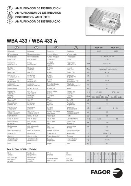
EFGBPAMPLIFICADOR DE DISTRIBUCIÓNAMPLIFICATEUR DE DISTRIBUTIONDISTRIBUTION AMPLIFIERAMPLIFICADOR DE DISTRIBUIÇÃO<strong>WBA</strong> <strong>433</strong> / <strong>WBA</strong> <strong>433</strong> AE F GB P<strong>WBA</strong> <strong>433</strong><strong>WBA</strong> <strong>433</strong> AReferenciaN.º de entradasN.º de salidasConectoresFrecuenciascubiertas 1ª FINivel desalida 1ª FIGanancia 1ª FIRegulaciónde ganancia 1ª FISelecciónde pendiente 1ª FIAdaptaciónentrada y salida FIReference Referência35930 35932Number of inputsN.º de entradas1Number of outputsN.º de saídas3 (out, test-in, test.out)Connectors1 st IF SATfrequenciescoveredFigura de ruido Facteur de bruitNoise Figure RuídodB8,5Frecuenciascubiertas RFNivel desalida RFGanancia RF Gain RFRF gain Ganho RFdB35Regulación deganancia RFRegulación dependiente RFAdaptaciónentrada y salida RFIF OutputlevelIF GainIF GainregulationIF SlopeSwitchRF Input and outputreturn lossesFigura de ruido Facteur de bruitNoise Figure RuídodB6,5Canal de retornoGanancia canalde retornoNivel de salidade testIF Input and outputreturn lossesRF OutputlevelReturn PathReturn PathgainTestoutput levelAlimentación AlimentationPower Supply AlimentaçãoV230 ± 15 %Consumo ConsommationPower Comsuption ConsumoW12Peso PoidsWeight PesoKg3,2MHzdBµVdBdBdBdBMHzdBµVdBdBdBMHzdBdBºCF (h)950 ÷ 2.300Índice de protección Indice de protection Weather protection Índice de protecçãoIP63Temperatura defuncionamientoRéférenceNombre de entréesNombre de sortiesConnecteursBandecouverte BISNiveau desortie BISGain BISDynamiquede gain BISSélectionde pente BISAdaptationentrée et sortie BISBandescouvertes RFNiveau desortie RFDynamiquede gain RFRéglage depente RFAdaptationentrée et sortie RFVoie de retourGain voie deretourAtténuation de laprise testTempérature defonctionnementRF FrequenciescoveredRF gainregulationRF SloperegulationOperatingtemperatureFichasFrequénciascobertas 1ª FINível desaída 1ª FIGanho 1ª FIRegulaçãode ganho 1ª FIRegulaçãode pendente 1ª FIAdaptaçãoentrada e saída 1ª FIFrequênciascobertas RFNivel desalida RFRegulaçãode ganho RFRegulaçãode pendente RFAdaptaçãoentrada e saída RFCanal do retornoGanho canaldo retornoNivel de saídade testeTemperatura defuncionamento117(DIN 45004B ; IM3 –35 dB)34 ÷ 41> 157 / 14647÷ 862 87,5 ÷ 862116(DIN 45004B;IM3 –60)200 ÷ 20 0 ÷ 18105 ÷ 30 5 ÷ 66–2–30–10 ÷ 50114(3p=;IM3 –52dB)Tabla 1 / Table 1 / Table 1 / Tabela 1Nº decanalesNombre detranspondeursNº. ofchannelsNºtranspo2 3 4 5 6 7 8 9 10 12 14 16Reducción delnivel máximode salidaRéduction deniveau max.de sortieMaximum outputlevel reductionReduçãonivel saidadB 0 -2 -3 -4 -5 -5,5 -6 -6,5 -7 -8 -8,5 -9
CONTROLES / COMMANDES / CONTROLS / LIGAÇÕESEFGBP1. Entrada2. Test en la entrada3. Test en la salida4. Salida5. Led de alimentación6. Regulación de nivel desalida 1ª FI SAT7. Conmutación de pendiente7 / 14 dB 1ª FI SAT8. Regulación de nivel desalida RF9. Regulación de pendienteen RF10. Entrada de red1. Entrée2. Prise Test d'entrée3. Prise Test de sortie4. Sortie5. Témoin d'alimentation6. Réglage de gain BIS7. Commutateur de penteBIS 7 / 14 dB8. Réglage de gain RF9. Réglage de pente RF10. Entrée secteur1. Input2. Input Test point3. Output Test point4. Output5. Operating Led6. 1 st IF SAT output levelregulation7. 1 st IF slope switch8. RF Output level regulation8. RF Slope control10. Mains plug1. Entrada2. Teste de entrada3. Teste de saída4. Saída5. Led de alimentação6. Regulação de nível de saída1ª FI SAT7. Comutação de pendente7 / 14 dB 1ª FI SAT8. Regulação de nível desaída RF9. Regulação de pendenteem RF10. Entrada de redeEFGBINSTALACIÓN Y PUESTA EN MARCHA• Situar el amplificador en una superficie verticalcon la entrada de red hacia abajo.• Conectar el cable de entrada en el conector F deentrada (1).• Conectar el equipo de medida en el conector F desalida (4).• Alimentar el <strong>WBA</strong> <strong>433</strong> con la tensión de red.• Retirar la tapa frontal para acceder a los controles.• Ajustar la ganancia de RF (8) al nivel operativomidiendo sobre el canal de mayor frecuencia yobservando la reducción según la Tabla 1.• Ajustar la ganancia de 1ª FI (6) al nivel operativomidiendo sobre la frecuencia más alta y observandola reducción según la Tabla 1.• Regulación de pendiente: Actuar sobre el control(9) para RF y el conmutador (7) para 1ª FI SATmidiendo sobre la frecuencia más baja.Consideraciones importantes:• Se debe hacer un buen acondicinado de loscables coaxiales evitando realizar curvas muypronunciadas tanto en la entrada como en lasalida. También es importante un buen aprietede los conectores “F” al equipo para conseguiruna buena respuesta.• Las tomas de test se deben utilizar paramonitorizar la calidad de la señal pero no paramedir el nivel de señal.• Por motivos de seguridad, se recomiendaconectar el amplificador a tierra mediante eltornillo disponible para ello.• No se debe quitar la tapa inferior delamplificador con el equipo en marcha ya queexisten altas tensiones dentro.Diagrama de niveles:• Ver Tabla 2 para el correcto equilibrado de niveles.Tabla 2 / Table 2 / Table 2 / Tabela 2MISE EN OEUVRE• Installer l'amplificateur sur une surface verticale,les connecteurs orientés vers le bas.• Connecter l'équipement de mesure sur la sortie(4) et mettre l'appareil sous tension.• Retirer le couvercle frontal pour accéder auxorganes de réglage.• Ajuster le gain RF (8) jusqu'à obtenir le niveau desortie nécessaire en observant le canal defréquence la plus élevée.• Ajuster le gain BIS (6) jusqu'à obtenir le niveau desortie nécessaire en observant le canal defréquence la plus élevée.• Ajuster le réglage de pente (6 pour la voie RF,et 7 pour la voie BIS) en observant les canaux defréquences les plus basses.Considerations importantes:• Vérifier que les rayons de courbure des câblessoient tels que ceux-ci n'exercent pas d'effort entorsion sur les connecteurs F.• La prise test est utile pour des contôles sansrupture de service. Pour un réglage del'appareil, il est toutefois préférable de réaliser lamesure sur la sortie principale.• Ne pas omettre de connecter l'amplificateur à laterre à l'aide de la vis prévue à cet effet.• Ne jamais retirer le couvercle inférieur del'amplificateur, à fortiori sous tension.INSTALLATION AND START-UP• Place the amplifier on a vertical surface, the mainsplug facing down.• Connect the input cable to the F-type inputconnector (1)• Connect the field strength meter to the F-typeoutput connector (4)• Connect the mains plug.• Take off the front cover, to access to the controldevices.• Regulate the amplifier to the necessary level ineach band, having in mind the maximum outputlevel for each band ( 116 dBµV in RF, and 117 dbµVin IF ), and considering the level reductiondepending on quantity of processed signals asshown in Table-1.• RF: Measure the most upper available UHFchannel and regulate the RF Gain (8).•1 st SAT IF: Measure the most upper available1 st SAT IF channel and regulate the 1st IF Gain (6).• RF Slope Regulation for each band: Sameprocedure as described above, but using control(9) for slope in RF, and using switch (7) for slope in1 st IF.• Connect the distribution coaxial cable to the F-typeoutput connector (4).Important questions:• Make sure that the F connectors are tightlyconnected on the cable, on input and output.Also, the cable must be fixed tightly on the unit inorder to obtain a good response.• The test points are to be used for display of thesignal quality, but not for measuring the outputlevel.• For measuring the levels of input and output, takeinto account the type of signal to be measured(analogue or digital) and be sure to use thecorresponding equipment.• For safety reasons, it is recommended to connectthe amplifier to ground by means of the specificscrew available.• Never take off the cover while the amplifier isconnected to the mains, since there is highvoltage inside.Level diagram:• See Table-2. Get the levels of your installationcorrectly balanced.JJK / FAGOR . <strong>WBA</strong> <strong>433</strong> • <strong>WBA</strong> <strong>433</strong> A/ 6 I / 2-00 • 02179954<strong>Fagor</strong> <strong>Electrónica</strong>, S.Coop.San Andrés, s/n.E-20500 Mondragón (Spain)Tel. +34 43 712526Fax +34 43 712893E- mail: rf.sales@fagorelectronica.eswww.fagorelectronica.com