1N5820 - 1N5822 3 Amp. Schottky Barrier Rectifiers Maximum ...
1N5820 - 1N5822 3 Amp. Schottky Barrier Rectifiers Maximum ...
1N5820 - 1N5822 3 Amp. Schottky Barrier Rectifiers Maximum ...

Create successful ePaper yourself
Turn your PDF publications into a flip-book with our unique Google optimized e-Paper software.
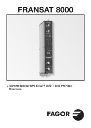
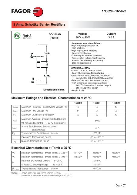
<strong>1N5820</strong> - <strong>1N5822</strong>3 <strong>Amp</strong>. <strong>Schottky</strong> <strong>Barrier</strong> <strong>Rectifiers</strong>PbDO-201AD(Plastic)Voltage20 V to 40 VCurrent3.0 A• Low power loss, high efficiency.• High current capability, low VF.• High reliability.• High surge current capability.• Epitaxial construction.• Guard-ring for transient protection.• For use in low voltage, high frequencyinventor, free wheeling, and polarityprotection application.Dimensions in mm.MECHANICAL DATA• Cases: DO-201AD molded plastic• Epoxy: UL 94V-0 rate flame retardant• Lead: Pure tin plated, lead free., solderableper MIL-STD-202, Method 208 guaranteed• Polarity: Color band denotes cathode end• High temperature soldering guaranteed:260 °C/10 seconds/9.5 mm lead lengthsat 5 Ibs., (2.3 Kg) tension• Weight: 1.10 g.<strong>Maximum</strong> Ratings and Electrical Characteristics at 25 ºCV RRMV RMSV DCI F(AV)I FSMC jT j<strong>1N5820</strong>1N5821<strong>Maximum</strong> Recurrent Peak Reverse Voltage (V)<strong>Maximum</strong> RMS Voltage (V)20143021<strong>Maximum</strong> DC Blocking Voltage (V)2030<strong>Maximum</strong> Average Forward Rectified Current9.5 mm Lead Lenght @ T L = 90 °C (See graphic)3.0 A8.3 ms.Peak Forward Surge Current80 A(Jedec Method)Typical Junction Capacitance (Note 2)200 pFOperating Temperature Range-65 to +125 °CT stg Storage Temperature Range -65 to +125 °C<strong>1N5822</strong>402840Electrical Characteristics at Tamb = 25 °CV F <strong>Maximum</strong> Instantaneous Forward Voltage I F = 3.0 A 0.475 V 0.500 V0.525 VV F <strong>Maximum</strong> Instantaneous Forward Voltage I F = 9.0 A 0.850 V 0.900 V0.950 VI RR th (j-a)<strong>Maximum</strong> DC Reverse Current Ta = 25 °Cat Rated DC Blocking Voltage Ta =125°CTypical Thermal Resistance(Note 1)0.5 mA10 mA40 °C/WNOTES:1. Mount on Cu-Pad Size 16mnm x 16mm on P.C.B.2. Measured at 1 MHz and Applied Reverse Voltage of 4.0 V D.C.Dec - 07
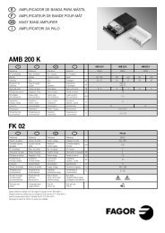
<strong>1N5820</strong> - <strong>1N5822</strong>Rating And Charasterictic CurvesTYPICAL FORWARD CHARACTERISTICMAXIMUM FORWARD CURRENT DERATINGCURVEIF, instantaneous forward current (A)20101<strong>1N5820</strong>1N5821-<strong>1N5822</strong>T j = 25 °CPulse Width = 300 µs1% Duty Cycle0.10.2 0.3 0.4 0.5 0.6 0.7 0.8 0.9V F , forward voltage (V)IF(AV), average forward Current (A)4321Resestive of Inductive Load9.5 mm Lead Length00 20 40 60 80 100 120 140Lead temperature (°C)IFSM, peak forward surge current (A)8070605030402001MAXIMUM NON-REPETITIVE FORWARDSURGE CURRENT8.3ms Single Half Sine WaveJEDEC Method2 5 10 20 50Number of cycles at 60 Hz100Cj, junction capacitance (pF)1000400100604020100.1TYPICAL JUNCTION CAPACITANCE0.4 1 44010V R , reverse voltage (V)100IR, Reverse current (mA)TYPICAL REVERSE CHARACTERISTIC1010.1T j = 100 °CT j = 75 °CT j = 25 °C0.010.0010 20 40 60 80 100 120 140Percent of rated peak reverse voltage (%)Transient thermal impedance (°C/W)100101TYPICAL TRANSIENT THERMALCHARACTERISTIC0.10.01 0.1 1 10 100t, Pulse duration (sec)Dec - 07