ART (5000 - 5012 - 5024) Operatore elettromeccanico ... - GiBiDi
ART (5000 - 5012 - 5024) Operatore elettromeccanico ... - GiBiDi
ART (5000 - 5012 - 5024) Operatore elettromeccanico ... - GiBiDi
- No tags were found...

You also want an ePaper? Increase the reach of your titles
YUMPU automatically turns print PDFs into web optimized ePapers that Google loves.
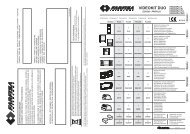
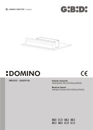
3I1 Coste sensibili.2 Contenitore apparecchiatura elettronica.3 Operatori. <strong>ART</strong><strong>5000</strong>: cavo a 7 conduttori da 1,5 mm².<strong>ART</strong><strong>5012</strong>, <strong>ART</strong><strong>5024</strong>: cavo a 5 conduttori da 1,5 mm² per distanze max.3mdall’apparecchiatura; per distanze maggiori cavo da 2.5mm² (max.6m).Inentrambi i casi 3 conduttori sono utilizzati per il collegamento dei finecorsa.4 Pulsantiera; cavo a 5 conduttori da 0,5 mm².5 Selettore a chiave; cavo a 3 conduttori da 0,5 mm².6 Linea di alimentazione all’apparecchiatura 220-230 V 50-60 Hz; cavo a 3conduttori da 1,5 mm² min. (attenersi alle Norme vigenti).7 Segnalatore a luce lampeggiante; cavo a 2 conduttori da 1,5 mm².8 Antenna.9 Trasmettitore fotocellula; cavo a 2 conduttori da 0,5 mm²10 Ricevitore fotocellula; cavo a 4 conduttori da 0,5 mm²11 Elettroserratura.ATTENZIONE: è importante che sulla linea di alimentazione venga installato, amonte dell’apparecchiatura, un interruttore magnetotermico onnipolare conaper tura minima dei contatti pari a 3 mm.F1 Barres palpeuses.2 Boîtier de la platine électronique.3 Opérateurs. <strong>ART</strong><strong>5000</strong>: câble à 7 conducteurs de 1,5 mm².<strong>ART</strong><strong>5012</strong>, <strong>ART</strong><strong>5024</strong>: câble à 5 conducteurs de 1,5 mm² pour distances max.3mde la platine de commande; pour distances supérieures câble de 2.5mm²(max.6m). Dans les deux cas 3 conducteurs sont utilisés pour la connexion desfins de course.4 Tableau de commande; câble à 5 conducteurs de 0,5 mm².5 Sélecteur à clé; câble à 3 conducteurs de 0,5 mm².6 Ligne d’alimentation de la platine 220-230 V 50-60 Hz; câble à 3 conducteurs de1,5mm2 mini (respecter les normes en vigueur).7 Clignotant; câble à 2 conducteurs de 1,5 mm².8 Antenne.9 Emetteur cellule photo-électrique; câble à 2 conducteurs de 0,5 mm².10 Récepteur cellule photo-électrique; câble à 4 conducteurs de 0,5 mm².11 Electroserrure.ATTENTION: Sur la ligne d’alimentation, en amont de la platine, il est importantde monter un interrupteur magnétothermique omnipolaire ayant une ouverturedes contacts minimale de 3 mm.UK1 Sensitive frame.2 Electronic equipment container.3 Operators. <strong>ART</strong><strong>5000</strong>: cable with 7 conductors of 1.5 mm².<strong>ART</strong><strong>5012</strong>, <strong>ART</strong><strong>5024</strong>: cable with 5 conductors of 1.5 mm² for distances max.3mfrom the control unit; for bigger distances cable of 2.5mm² (max.6m). In bothcases 3 conductors are used for the limit switch connection.4 Push-button panel; cable with 5 conductors of 0.5 mm².5 Key-selector; cable with 3 conductors of 0.5 mm².6 Power supply line to equipment 220-230V 50-60Hz, cable with 3 conductors ofmin. 1.5 mm² (follow regulations in force).7 Flashing light; cable with 2 conductors of 1,5 mm².8 Antenna.9 Photocell transmitter; cable with 2 conductors of 0.5 mm².10 Photocell receiver; cable with 4 conductors of 0.5 mm².11 Electric lock.WARNING: It is important that an omnipolar magneto-thermal switch with acontact opening of minimum 3 mm is installed on the power supply line,upstream of the equipment.E1 Bandas sensibles.2 Contenedor del equipo electrónico.3 Operadores. <strong>ART</strong><strong>5000</strong>: cable de 7 conductores de 1,5 mm².<strong>ART</strong><strong>5012</strong>, <strong>ART</strong><strong>5024</strong>: cable de 5 conductores de 1,5 mm² para distancias max.3m del equipo de mando; para distancias superiores cable de 2.5mm²(max.6m). En ambos casos 3 conductores son utilizados para la conexión de losfinales de carrera.4 Botonera; cable de 5 conductores de 0,5 mm².5 Selector de llave; cable de 3 conductores de 0,5 mm².6 Línea de alimentación al equipo 220-230 V 50-60 Hz; cable de 3 conductores de1,5 mm² (mínimo) (atenerse a las normas vigentes).7 Destellador; cable de 2 conductores de 1,5 mm².8 Antena.9 Fotocélula transmisora; cable de 2 conductores de 0,5 mm².10 Fotocélula receptora; cable de 4 conductores de 0,5 mm².11 Electrocerradura.ATENCIÓN: es importante instalar en la línea de alimentación, antes del equipo,un interruptor magnetotérmico omnipolar con abertura mínima de loscontactos igual a 3 mm.P1 Banda sensível.2 Caixa da aparelhagem electrónica.3 Operador. <strong>ART</strong><strong>5000</strong>: cabo com 7 condutores de 1,5 mm².<strong>ART</strong><strong>5012</strong>, <strong>ART</strong><strong>5024</strong>: cabo com 5 condutores de 1,5 mm² para distância máx.de3m do aparelho; para distâncias maiores, cabo de 2.5mm² (máx.6m). Emambos os casos são utilizados 3 condutores para a ligação dos interruptores defim de curso.4 Painel de terminais; cabo com 4 condutores de 0,5 mm².5 Selector de chave; cabo com 3 condutores de 0,5 mm².6 Linha de alimentação da aparelhagem 220-230 V 50-60 Hz; cabo com 3condutores de 1,5 mm² mín. (respeitar as normas vigentes).7 Lâmpada pisca-pisca a 220 V ou 12 V; cabo com 2 condutores de 1,5mm².8 Antena.9 Transmissor fotocélula; cabo com 2 condutores de 0,5 mm².10 Receptor fotocélula; cabo com 4 condutores de 0,5 mm².11 Fechadura eléctrica; cabo com 2 condutores de 1,5 mm².ATENCIÓN: é impor tante instalar sobre a linha de alimentação, antes daaparelhagem, um interruptor magnetotérmico omnipolar com abertura mínimados contactos igual a 3 mm.D1 Kontaktschienen2 Steuergerätgehäuse3 Antrieb <strong>ART</strong><strong>5000</strong>: 7-Leiter-Kabel 1,5 mm².<strong>ART</strong><strong>5012</strong>, <strong>ART</strong><strong>5024</strong>: 5-Leiter-Kabel 1,5 mm² für Entfernungen bis max.3m vomGerät; für größere Entfernungen kabel mit 2.5mm² (bis max.6m). Bei beidenAusführungen werden 3 Leiter für den Anschluss der Endschalter verwendet.4 Druckknopftafel: 5-Leiter-Kabel 0,5 mm²5 Schlüsselschalter: 3-Leiter-Kabel 0,5 mm²6 Versorgungsleitung zum Steuergerät 220-230V, 50-60 Hz: 3-Leiter- Kabel 1,5mm² (die geltenden Vorschriften befolgen).7 Blinklicht: 2-Leiter-Kabel 1,5 mm²8 Antenne9 Lichtschrankensender: 2-Leiter-Kabel 0,5 mm²10 Lichtschrankenempfänger: 4-Leiter-Kabel 0,5 mm²11 ElektroschlossACHTUNG: An der Versorgungsleitung vor dem Steuergerät unbedingt einenallpoligen, thermomagnetischen Schalter mit einer Kontaktweite vonmindestens 3 mm anbringen.NL1 Veiligheidsstrip2 Besturingskast3 Openers <strong>ART</strong><strong>5000</strong> - 7 draden sectie 1,5 mm²<strong>ART</strong><strong>5012</strong>, <strong>ART</strong><strong>5024</strong> - 5 draden sectie 1,5 mm² voor een max. afstand van 3 meter vande apparatuur; voor langere afstanden, kabel van 2.50mm² (max.6meter). waarvan 3draden worden gebruikt door de aansluiting van de einderitschakelaars4 Drukknoppaneel : 5 draden sectie 0,5 mm²5 Sleutelcontact : 3 draden sectie 0,5 mm²6 Voedingsspanning 220-230 V, 50-60 Hz : 3 draden min. sectie 1,5 mm5(respecteer de van kracht zijnde normen)7 Knipperlicht 220 V : 2 draden sectie 1,5 mm²8 Antenne9 Infrarood fotocel zender : 2 draden sectie 0,5 mm²10 Infrarood fotocel ontvanger : 4 draden sectie 0,5 mm².11 Elektrisch slotOPGELET : Het is heel belangrijk dat er een onderbrekingsschakelaar wordtgeplaatst op alle voedingsdraden. De minimum opening van dezeschakelcontacten moet 3 mm. bedragen.
4AVVERTENZE PRELIMINARIMISES EN GARDE PRELIMINAIRESPRELIMINARY WARNINGSADVERTENCIAS PRELIMINARESADVERTÊNCIAS PRELIMINARESVORBEREITENDE HINWEISEVOORAFGAANDE WAARSCHUWINGENIAVVERTENZE PRELIMINARIVerificare che la struttura del cancello sia conforme a quanto previsto dallenormative vigenti e che il movimento delle ante sia lineare e privo di attriti. Siraccomanda di effettuare gli eventuali interventi prima di installare l’automazionee in particolare di prevedere sempre gli arresti meccanici di finecorsa.INSTALLAZIONE DELL’ATTUATOREVerifiche preliminari:- controllare che la struttura del cancello sia sufficentemente robusta. In ogni casol’attuatore deve spingere l’anta in un punto rinforzato.- contollare che le ante si muovano manualmente e senza sforzo per tutta la corsa- contollare che siano installate le battute di arresto delle ante.- se il cancello non è di nuova installazione, controllare lo stato di usura di tutti icomponenti, sistemare o sostituire le parti difettose o usurate.L’affidabilità e la sicurezza dell’automazione, è direttamente influenzata dallostato della struttura del cancello.FMISES EN GARDE PRELIMINAIRESVérifier que la structure du portail est conforme conformément auxréglementations en vigueur et que le mouvement des vantaux est linéaire et n’estpas soumis à frottements. Il recommandé d’effectuer les interventions éventuellesavant d’installer l’automation et en particulier, il faut toujours prévoir les butéesmécaniques de fin de course.INSTALLATION DE L’ACTIONNEURVérifications préliminaires:- contrôler que la structure du portail est suffisamment robuste. Dans tous les cas,l’actionneur doit pousser le vantail sur un point renforcé.- contrôler que les vantaux se déplacent manuellement et sans effort sur toute lacourse.- contrôler que les butées d’arrêt des vantaux sont installées.- si le portail n’a pas été récemment installé, contrôler l’état d’usure de tous sescomposants, réparer ou remplacer les pièces défectueuses ou usées.La fiabilité et la sécurité de l’automation dépend directement de l’état de lastructure du por tail.UKPRELIMINARY WARNINGSCheck that the gate structure meets the standards laid down in the regulations inforce and that the gate movement is linear and without friction. It is recommendedto carry out any operations necessary before installing the operator and inparticular to always fit the mechanical end-stops.OPERATOR INSTALLATIONPreliminary checks:- Check that the gate structure is sufficiently robust. In any event, the operatormust push the gate at a reinforced point.- Check that the gates move manually without effort for their entire travel.- Check that the gate stops have been installed.- If the gate is not a new installation, check the state of wear of all the componentsand repair or replace the defective or worn parts.The reliability and safety of the automated device is directly affected by thestate of the gate structure.EADVERTENCIAS PRELIMINARESVerifique que la estructura de la cancela sea conforme a lo previsto por lasnormativas vigentes y que el movimiento de las puertas sea linear y quenopresente fricciones. Se recomienda efectuar las posibles intervenciones antesde instalar la automación y en especial prever siempre los paros mecánicos definal de carrera.INSTALACIÓN DEL ACTUADORVerificaciones preliminares:- controle que la estructura de la cancela sea lo suficientemente resistente. Entodo caso, el actuador debe empujar la puerta hacia un punto reforzado.- controle que las puertas se muevan manualmente y sin esfuerzo durante toda lacarrera.- controle que estén instalados los topes de parada de las puertas- si la cancela se ha instalado anteriormente, controle el estado de usura de todoslos componentes, arregle o sustituya las partes defectuosas o usuradas.La fiabilidad y la seguridad de la automación es directamente condicionadapor el estado de la estructura de la cancela.PADVERTÊNCIAS PRELIMINARESVerificar que a estrutura do portão seja uniforme conforme previsto pelas leis emvigor e que o movimento dos batentes seja linear e sem atritos. Recomenda-se arealização de eventuais intervenções antes de instalar o automatismo e emparticular prever sempre as paragens mecânicas de fim-decursoINSTALAÇÃO DO ACTUADORVerificações preliminares:- verificar que a estrutura do portão seja suficientemente resistente. De qualquerforma o actuador deve empurrar o batente num ponto reforçado.- verificar que os batentes movimentam-se manualmente e sem esforço durantetodo o curso- verificar que estão instalados os mecanismos de bloqueio dos batentes- se o portão não for novo, verificar o estado de desgaste de todas ascomponentes, e arranjar ou substituir as partes defeituosas ou gastas.A facilidade e a segurança do automatismo, são directamente influenciadaspelo estado da estrutura do por tão.DVORBEREITENDE HINWEISEÜberprüfen Sie, dass die Struktur des Tors gemäss die geltende Gesetze und dieBewegung der Flügel linear und frei von Reibung ist. Es wird empfohlen, dieeventuellen Eingriffe vor der Installation der Automatisierung auszuführen undinsbesondere immer für die mechanischen Endschalter zu sorgen.INSTALLATION DES ANTRIEBSVorbereitende Überprüfungen:- Kontrollieren Sie, dass die Struktur des Tores hinreichend robust ist. In jedemFall muss der Ansatzpunkt des Antriebs auf dem Flügel verstärkt sein.- Kontrollieren Sie, dass sich die Flügel auf dem gesamten Lauf manuell und leichtbewegen lassen.- Kontrollieren Sie, dass die Stoppanschläge der Flügel installier t sind.- Wenn das Tor nicht neu installiert ist, muss der Abnutzungszustand allerKomponenten überprüft werden. Die defekten oder abgenutzten Teile reparierenoder auswechseln.Die Zuverlässigkeit und die Sicherheit der Automatisierung wird direkt vondem Zustand der Torstruktur beeinflusst.NLVOORAFGAANDE WAARSCHUWINGENControleer of de constructie van het hek in overeenstemming is met de geldenderichtlijnen en dat de beweging van het hek egaal is en zonder wrijving. Het isaanbevolen alle noodzakelijke werkzaamheden, met inbegrip van de mechanischeeindstoppen (in open- en sluitrichting), uit te voeren vooraleer de openers teplaatsen.INSTALLATIE VAN DE OPENERVoorafgaande controles:- Controleer of de constructie van het hek voldoende stevig is. In elk geval dientde opener op een verstevigde plaats van het hek te duwen.- Controleer of het hek zich beweegt zonder grote vereiste krachten over zijnvolledige loopbeweging.- Controleer of de mechanische eindstoppen zijn geplaatst.- Indien het hek geen nieuwe installatie is, controleer dan alle bewegendeonderdelen op slijtage en indien nodig, herstel of vervang de defecte onderdelen.De betrouwbaarheid en de veiligheid van de automatische openers kunnenonmiddellijk worden beïnvloed door de toestand van de constructie van het hek.
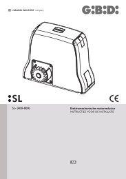
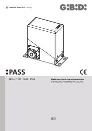
5QUOTE D’INSTALLAZIONECOTAS DE INSTALAÇÃOCOTES D’INSTALLATIONINSTALLATIONSMASSE321INSTALLATION QUOTASTECHNISCHE GEGEVENSCOTAS DE INSTALACIÓN51446946531531201709315FIG.1APPLICAZIONE DELL’OPERATORE PER APERTURA ANTA DI 90° MAXAPPLICATION DE L’OPERATEUR POUR OUVERTURE VANTAIL DE 90° MAXIAPPLICATION OF THE OPERATOR FOR MAX. 90° WING OPENINGAPLICACIÓN DEL OPERADOR PARA APERTURA HOJA EN 90º MÁX.MONTAGEM DO OPERADOR PARABERTURA DO PORTÃO DE 90° MAX.MONTAGE DES ANTRIEBS FÜR EINE ÖFFNUNGSWEITE DES TORFLÜGELS VON MAX. 90°PLAATSING VAN DE OPENERS VOOR EEN MAXIMUM OPENING VAN 90°5/6°10013590°589135 315 1707520401355/6°FIG.2130°APPLICAZIONE DELL’OPERATORE PER APERTURA ANTA SUPERIORE A 90°APPLICATION DE L’OPERATEUR POUR OUVERTURE VANTAIL SUPERIEURE A 90°APPLICATION OF THE OPERATOR FOR OVER 90° WING OPENINGAPLICACIÓN DEL OPERADOR PARA APERTURA HOJA SUPERIOR A 90ºMONTAGEM DO OPERADOR PARA ABER TURA DO PORTÃO POR MAIS DE 90°MONTAGE DES ANTRIEBS FÜR EINE ÖFFNUNGSWEITE DES TORFLÜGELS ÜBER 90°PLAATSING VAN DE OPENERS VOOR EEN OPENING VAN MEER DAN 90°
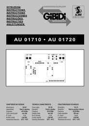
8COLLEGAMENTI ELETTRICICONNEXIONS ELECTRIQUESELECTRICAL CONNECTIONSCONEXIONES ELECTRICASLIGAÇÕES ELÉCTRICASELEKTROANSCHLÜSSEELECTRISCHE AANSLUITINGEN<strong>ART</strong><strong>5000</strong>MARRONEBROWNBLUBLUENEROBLACKBIANCOWHITELATO MOTOREMOTORMARRONEBROWNBLUBLUEBLUBLUE1 2 3 4 5 6 7MORSETTIERATERMINAL BLOCK1 2 3 4 5 6 7COMFCAFCACOMFCCFCC MOT COMMOTMOT(FCC)(FCA)LATO SCHEDACONTRO L BOARD<strong>ART</strong><strong>5012</strong>NEROBLACKLATO MOTOREMOTORROSSORED1 2MORSETTIERATERMINAL BLOCKMOTMOT1 2LATO SCHEDACONTRO L BOARD<strong>ART</strong><strong>5024</strong>1 2 3 4 5 6COMFCA(FCC)FCA(FCA)COMFCC FCC MOT MOTLATO SCHEDACONTRO L BOARD1 2 3 4 5 6MORSETTIERATERMINAL BLOCKMARRONEBROWNBLUBLUEROSSOREDMARRONEBROWNBLUBLUENEROBLACKLATO MOTOREMOTOR
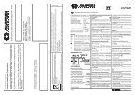
9COLLEGAMENTI ELETTRICICONNEXIONS ELECTRIQUESELECTRICAL CONNECTIONSCONEXIONES ELECTRICASLIGAÇÕES ELÉCTRICASELEKTROANSCHLÜSSEELECTRISCHE AANSLUITINGENI<strong>ART</strong><strong>5000</strong> (230Vac)1 Comune Finecorsa apertura2 Finecorsa apertura; finecorsa di chiusura con operatore installato a sinistra.3 Comune Finecorsa chiusura4 Finecorsa chiusura; finecorsa di apertura con operatore installato a sinistra.5-6-7 Alimentazione del motore a 230V; il filo 6 è il comune<strong>ART</strong><strong>5012</strong> (12Vdc)1-2 Alimentazione del motore a 12Vdc<strong>ART</strong><strong>5024</strong> (24Vdc)1 Comune Finecorsa apertura2 Finecorsa apertura; finecorsa di chiusura con operatore installato a sinistra.3 Comune Finecorsa chiusura4 Finecorsa chiusura; finecorsa di apertura con operatore installato a sinistra.5-6 Alimentazione del motore a 24VdcF<strong>ART</strong><strong>5000</strong> (230Vac)1 Commun Fin de course d’ouverture2 Fin de course d’ouverture; fin de course de fermeture avec opérateur installé à gauche.3 Commun Fin de course de fermeture4 Fin de course de fermeture; fin de course d’ouverture avec opérateur installé à gauche.5-6-7 Alimentation du moteur à 230V; le fil 6 est le commun<strong>ART</strong><strong>5012</strong> (12Vdc)1-2 Alimentation du moteur à 12Vdc<strong>ART</strong><strong>5024</strong> (24Vdc)1 Commun Fin de course d’ouverture2 Fin de course d’ouverture; fin de course de fermeture avec opérateur installé à gauche.3 Commun Fin de course de fermeture4 Fin de course de fermeture; fin de course d’ouverture avec opérateur installé à gauche.5-6 Alimentation du moteur à 24VdcUK<strong>ART</strong><strong>5000</strong> (230Vac)1 Common Opening limit switch2 Opening limit switch; closing limit switch with operator installed on the left.3 Common Closing limit switch4 Closing limit switch; opening limit switch with operator installed on the left.5-6-7 230V motor power supply; 6 is the common wire<strong>ART</strong><strong>5012</strong> (12Vdc)1-2 12Vdc motor power supply<strong>ART</strong><strong>5024</strong> (24Vdc)1 Common Opening limit switch2 Opening limit switch; closing limit switch with operator installed on the left.3 Common Closing limit switch4 Closing limit switch; opening limit switch with operator installed on the left.5-6 24Vdc motor power supplyE<strong>ART</strong><strong>5000</strong> (230Vac)1 Común de Final de carrera en apertura2 Final de carrera apertura; final de carrera de cierre con operador instalado a la izquierda.3 Común de Final de carrera en cierre4 Final de carrera cierre; final de carrera de apertura con operador instalado a la izquierda.5-6-7 Alimentación del motor de 230V; el 6 es el hilo común<strong>ART</strong><strong>5012</strong> (12Vdc)1-2 Alimentación del motor de 12Vdc<strong>ART</strong><strong>5024</strong> (24Vdc)1 Común de Final de carrera en apertura2 Final de carrera apertura; final de carrera de cierre con operador instalado a la izquierda.3 Común de Final de carrera en cierre4 Final de carrera cierre; final de carrera de apertura con operador instalado a la izquierda.5-6 Alimentación del motor de 24VdcP<strong>ART</strong><strong>5000</strong> (230Vac)1 Comum Fim de curso de abertura2 Fim de curso de abertura; fim-de-curso de encerramento com operador instalado à esquerda.3 Comum de Fim de curso de fecho4 Fim de curso de fecho; fim-decurso de abertura com operador instalado à esquerda.5-6-7 Alimentação do motor 230V; o fio nº6 é o comum<strong>ART</strong><strong>5012</strong> (12Vdc)1-2 Alimentação do motor 12Vdc<strong>ART</strong><strong>5024</strong> (24Vdc)1 Comum Fim de curso de abertura2 Fim de curso de abertura; fim-de-curso de encerramento com operador instalado à esquerda.3 Comum de Fim de curso de fecho4 Fim de curso de fecho; fim-decurso de abertura com operador instalado à esquerda.5-6 Alimentação do motor 24VdcD<strong>ART</strong><strong>5000</strong> (230Vac)1 Gemeinsam Öffnungsendschalter2 Öffnungsendschalter; Schließungsendschalter bei links montiertem Antrieb.3 Gemeinsam Schließungsendschalter4 Schließungsendschalter; Endschalter Öffnen bei links montiertem Antrieb.5-6-7 Versorgungsleitung zum Motor 230V; Draht 6 wird gemeinsam verwendet<strong>ART</strong><strong>5012</strong> (12Vdc)1-2 Versorgungsleitung zum Motor 12Vdc<strong>ART</strong><strong>5024</strong> (24Vdc)1 Gemeinsam Öffnungsendschalter2 Öffnungsendschalter; Schließungsendschalter bei links montiertem Antrieb.3 Gemeinsam Schließungsendschalter4 Schließungsendschalter; Endschalter Öffnen bei links montiertem Antrieb.5-6 Versorgungsleitung zum Motor 24VdcNL<strong>ART</strong><strong>5000</strong> (230Vac)1 Gemeenschappelijke Einderitschakelaar openen2 Einderitschakelaar openen; Einderitschakelaar sluiten met de opener links geplaatst.3 Gemeenschappelijke einderitschakelaars sluiten4 Einderitschakelaar sluiten; Einderitschakelaar openen met de opener links geplaatst.5-6-7 Voedingsdraad motor 230V;draad nr.6 gemeenschapplijke<strong>ART</strong><strong>5012</strong> (12Vdc)1-2 Voedingsdraad motor 12Vdc<strong>ART</strong><strong>5024</strong> (24Vdc)1 Gemeenschappelijke Einderitschakelaar openen2 Einderitschakelaar openen; Einderitschakelaar sluiten met de opener links geplaatst.3 Gemeenschappelijke einderitschakelaars sluiten4 Einderitschakelaar sluiten; Einderitschakelaar openen met de opener links geplaatst.5-6 Voedingsdraad motor 24Vdc
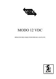
10MANOVRA MANUALEMANOUVRE MANUELLE1MANUAL OPERATIONMANIOBRA MANUALMANOBRA MANUALMANUELLE BEWEGUNGMANUELE ONTGRENDELING11GIBIDI212IDISPOSITIVO PER LA MANOVRA MANUALETogliere il coperchio (2) dalla serratura che permette d’innestare la chiave (1) persbloccare l'operatore; quindi ruotare la chiave (1) in senso orario fino a quandonon si ferma senza forzarla ed eseguire la manovra manuale.Per il ripristino ruotare la chiave (1) in senso antiorario fino a quando non siferma senza forzarla. Togliere la chiave (1) e rimettere il coperchio (2) sullaserratura.ATTENZIONE: effettuare le operazioni per la manovra manuale con motorefermo.FDISPOSITIF POUR LA MANOEUVRE MANUELLEEnlever le couvercle (2) de la serrure permettant d’enfoncer la clé (1) pourdéverrouiller l’opérateur, puis tourner la clé (1) dans le sens des aiguilles d’unemontre jusqu’à l’arrêter sans la forcer. Ensuite, exécuter la manoeuvre manuelle.Pour le rétablissement tourner la clé (1) dans le sens inverse à celui des aiguillesd’une montre jusqu’à l’arrêter sans la forcer. Enlever la clé (1) et positionner denouveau le couvercle (2) sur la serrure.ATTENTION: Effectuer les opérations de manoeuvre manuelle après avoir arrêtéle moteur.UKDEVICE FOR MANUAL OPERATIONRemove the lock cover (2) which allows inserting the key (1) to unlock theoperator.Turn the key (1) clockwise until it stops without forcing it and carry out themanual operation. To reset, turn the key (1) anticlockwise until itstops without forcing it. Remove the key (1) and replace the lock cover (2).WARNING: Carry out the manual operations with the motor off.EDISPOSITIVO PARA LA MANIOBRA MANUALQuitar la tapa (2) de la cerradura que permite introducir la llave (1) paradesbloquear el operador; luego girar la llave (1) a derechas hasta el tope sinforzarla y cumplir la maniobra manual.Para el restablecimiento, girar la llave (1) a izquierdas hasta el tope sin forzarla.Quitar la llave (1) y volver a colocar la tapa (2)sobre la cerradura.ATENCIÓN: cumplir las operaciones para la maniobra manual con motor parado.PDISPOSITIVO DE MANOBRA MANUALRetirar a tampa (2) da fechadura que permite introduzir a chave (1) paradesbloquear o operador; a seguir rodar a chave (1) no sentido horário até quandonão pára, sem a forçar e efectuar a manobra manual.Para restabelecer, rodar a chave (1) no sentido anti-horário até ao fim, sem aforçar. Retirar a chave (1) e montar a tampa (2) na fechadura.ATENÇÃO: efectuar as operações para a manobra manual com o motor parado.DVORRICHTUNG FÜR DIE MANUELLE BEWEGUNGDen Deckel (2) vom Schloss abnehmen, in das der Schlüssel (1) zum Entriegelndes Antriebs eingesteckt wird. Dann den Schlüssel (1) behutsam im Uhrzeigersinnbis zum Anschlag drehen und die manuelle Bewegung ausführen.Zum Zurückschalten den Schlüssel (1) behutsam im Uhrzeigersinn bis zumAnschlag drehen. Den Schlüssel (1) abziehen und den Schlossdeckel (2) wiederschließen.ACHTUNG: Die manuelle Bewegung bei stillstehendem Motor durchführen.NLMANUEEL ONTGRENDELINGSSYSTEEMVerwijder de afschermdop (2) en draai met de ontgrendelingssleutel (1) inuurwijzerzin zover U kan zonder grote krachten uit te oefenen. Dan kan hethekken voorzichtig manueel bediend worden. Om het hekken terug automatischte bedienen, draai met de ontgrendelingssleutel (1) tegenuurwijzerzin zover Ukan zonder grote krachten uit te oefenen. Verwijder de sleutel (1) en plaatstterug de afschermdop.OPGELET : De manuele ontgrendeling kan slechts gebeuren wanneer de openerniet in werking is.
11ELETTROSERRATURAFECHADURA ELÉCTRICAELECTROSERRUREELEKTROSCHLOSSELECTROLOCKELEKTRISCH SLOTELECTROCERRADURA7274654324313155E6MONTAJE DE LA ELECTROCERRADURA1 Electrocerradura2 Placa de fijación de la electrocerradura3 Cerradero del pestillo4 Tope para el cerradero del pestillo5 Pestillo6 Cilindro doble (sobre pedido)7 RejaIMONTAGGIO ELETTROSERRATURA1 Elettroserratura2 Piastra di fissaggio elettroserratura3 Bocchetta4 Battuta per bocchetta5 Scrocco6 Cilindro passante (a richiesta)7 CancelloFMONTAGE DE L’ELECTROSERRURE1 Electroserrure2 Tôle de fixation de l’électroserrure3 Gâche du pêne4 Epaulement pour la gâche du pêne5 Pêne6 Cylindre à double sortie (sur demande)7 GrillePMONTAGEM DA FECHADURA ELÉCTRICA1 Fechadura eléctrica2 Chapa de fixação da fechadura eléctrica3 Enganchamento do ferrolho4 Batente para enganchamento do ferrolho5 Ferrolho6 Cilindro duplo (a pedido)7 PortãoDMONTAGE DES ELEKTROSCHLOSSES1 Elektroschloss2 Befestigungsplatte Elektroschloss3 Riegelanschluss4 Riegelanschlussanschlag5 Riegel6 Doppelausgang-Zylinder (auf Wunsch)7 TorUKNLMOUNTING THE ELECTROLOCK1 Electrolock2 electrolock fixing plate3 Bolt hooker4 Bolt hooking rabbet5 Bolt6 Key cylinder (on request)7 GateMONTAGE VAN HET ELEKTRISCH SLOT1 Elektrisch slot2 Bevestigingsplaat van het elektrisch slot3 Penvanger4 Bevestigingsplaat van de penvanger5 Pen6 Cilinderslot (op aanvraag)7 Poort
12Dichiarazione di conformità CECE Declaration of conformityIl fabbricante:GI.BI.DI. S.r.l.Via Abetone Brennero, 177/B,46025 Poggio Rusco (MN) ITALYDichiara che i prodotti:Operatori elettromeccanici: <strong>ART</strong><strong>5000</strong>, <strong>ART</strong><strong>5012</strong>, <strong>ART</strong><strong>5024</strong>Sono conformi alle seguenti Direttive CEE:• Direttiva LVD 2006/95/CE e successive modifiche;• Direttiva EMC 2004/108/CE e successive modifiche;The manufacturer:GI.BI.DI. S.r.l.Via Abetone Brennero, 177/B,46025 Poggio Rusco (MN) ITALYDeclares that the products:Electromechanical operators: <strong>ART</strong><strong>5000</strong>, <strong>ART</strong><strong>5012</strong>, <strong>ART</strong><strong>5024</strong>Are in conformity with the following CEE Directives:• LVD Directive 2006/95/CE and subsequent amendments;• EMC Directive 2004/108/CE and subsequent amendments;e che sono state applicate le seguenti norme armonizzate:• EN61000-6-1, EN61000-6-3, EN60335-1Data 16/09/08and that the following harmonised standards have been applied:• EN61000-6-1, EN61000-6-3, EN60335-1Date 16/09/08Firma Ammistratore DelegatoOliviero ArosioManaging DirectorOliviero ArosioDéclaration de conformité CEDeclaración de conformidad CELa société:GI.BI.DI. S.r.l.Via Abetone Brennero, 177/B,46025 Poggio Rusco (MN) ITALYDéclare que les produits:Opérateurs electromecaniques: <strong>ART</strong><strong>5000</strong>, <strong>ART</strong><strong>5012</strong>, <strong>ART</strong><strong>5024</strong>Sont en conformité avec les exigences des Directives CEE:• Directive LVD 2006/95/CE et ses modifications;• Directive EMC 2004/108/CE et ses modifications;El fabricante:GI.BI.DI. S.r.l.Via Abetone Brennero, 177/B,46025 Poggio Rusco (MN) ITALYDeclara que los productos:Operadores electromecanicos: <strong>ART</strong><strong>5000</strong>, <strong>ART</strong><strong>5012</strong>, <strong>ART</strong><strong>5024</strong>Cumplen la siguiente Directiva CEE:• Directiva LVD 2006/95/CE y modificaciones sucesivas;• Directiva EMC 2004/108/CE y modificaciones sucesivas;et que les normes harmonisées suivantes ont été appliquées:• EN61000-6-1, EN61000-6-3, EN60335-1Date 16/09/08y que se han aplicado las siguientes normas armonizadas:• EN61000-6-1, EN61000-6-3, EN60335-1Fecha 16/09/08Signature Administrateur DéléguéOliviero ArosioFirma Administrador DelegadoOliviero Arosio
13CE-KonformitätserklärungDeclaração de conformidade CEDer Hersteller:GI.BI.DI. S.r.l.Via Abetone Brennero, 177/B,46025 Poggio Rusco (MN) ITALYErklärt, dass die Produkte:Elektromechanischer antriebe: <strong>ART</strong><strong>5000</strong>, <strong>ART</strong><strong>5012</strong>, <strong>ART</strong><strong>5024</strong>Den folgenden CEE-Richtlinien entsprechen:• LVD-Richtlinie 2006/95/CE und nachfolgende Änderungen;• EMV-Richtlinie 2004/108/CE und nachfolgende Änderungen;O fabricante:GI.BI.DI. S.r.l.Via Abetone Brennero, 177/B,46025 Poggio Rusco (MN) ITALYDeclara que os produtos:operadores electromecânicos: <strong>ART</strong><strong>5000</strong>, <strong>ART</strong><strong>5012</strong>, <strong>ART</strong><strong>5024</strong>Estão em conformidade com as seguintes Directivas CEE:• Directiva LVD 2006/95/CE e alterações posteriores;• Directiva EMC 2004/108/CE e alterações posteriores;und dass die nachfolgenden harmonisierten Vorschriftenangewendet wurden:• EN61000-6-1, EN61000-6-3, EN60335-1Data 16/09/08Unterschrift des GeschäftsführersOliviero Arosioe que foram aplicadas as seguintes normas harmonizadas:• EN61000-6-1, EN61000-6-3, EN60335-1Data 16/09/08Assinatura do Administrador DelegadoOliviero ArosioCE-ConformiteitsverklaringDe fabrikant:GI.BI.DI. S.r.l.Via Abetone Brennero, 177/B,46025 Poggio Rusco (MN) ITALYVerklaart dat de producten:Elektromechanische opener: <strong>ART</strong><strong>5000</strong>, <strong>ART</strong><strong>5012</strong>, <strong>ART</strong><strong>5024</strong>Conform de volgende CEE-richtlijnen zijn:• Richtlijn LVD 2006/95/CE en daaropvolgende wijzigingen;• Richtlijn EMC 2004/108/CE en daaropvolgende wijzigingen;en dat de volgende geharmoniseerde normen werden toegepast:• EN61000-6-1, EN61000-6-3, EN60335-1Datum 16/09/08Handtekening ZaakvoerderOliviero Arosio
AIC2781 - 11/08 - REV02GI.BI.DI. S.r.l.Via Abetone Brennero, 177/B46025 Poggio Rusco (MN) - ITALYTel. +39.0386.52.20.11Fax +39.0386.52.20.31E-mail: comm@gibidi.comNumero Verde: 800.290156w w w . g i b i d i . c o m