NONFOLD TC-65 STOOL TABLE MESA CON BANCOS ... - Sico Inc.
NONFOLD TC-65 STOOL TABLE MESA CON BANCOS ... - Sico Inc.
NONFOLD TC-65 STOOL TABLE MESA CON BANCOS ... - Sico Inc.
- No tags were found...

You also want an ePaper? Increase the reach of your titles
YUMPU automatically turns print PDFs into web optimized ePapers that Google loves.
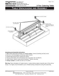
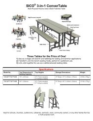
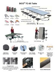
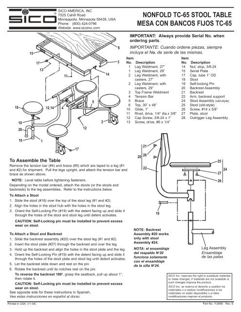
SICO AMERICA, INC7525 Cahill RoadMinneapolis, Minnesota 55439, USAPhone: (800) 424-0796Website: www.sicoinc.com<strong>NONFOLD</strong> <strong>TC</strong>-<strong>65</strong> <strong>STOOL</strong> <strong>TABLE</strong><strong>MESA</strong> <strong>CON</strong> <strong>BANCOS</strong> FIJOS <strong>TC</strong>-<strong>65</strong>IMPORTANT: Always provide Serial No. whenordering parts.18192815171312,1441112521463IMPORTANTE: Cuando ordene piezas, siempreincluya el No. de serie de las mismas.ItemItemNo. Description1 Leg Weldment, 27”1 Leg Weldment, 29”2 Leg Weldment, withcasters, 27”2 Leg Weldment, withcasters, 29”3 Top Frame Weldment4 Tension Bar5 Brace6 Top, 30” x 48”10 Glide, 1”11 Rivet, drive, 1/4” dia.x 3/8”12 Cap Screw, 3/8-24 x 1”13 Screw, drive, #6 x 1/4”No. Description14 Nut, stop, 3/8-2415 Serial Plate17 Cap, tube 1” OD18 Stool19 Self-locking Pin20 Backrest Assembly21 Backrest22 Arm, backrest support24 Stool Assembly (old-style)25 Stool (old-style)26 Screw, #14 x 5/8”27 Plate, stool28 Outrigger Leg Assembly10Printed in USA (11-04)1To Assemble the TableRemove the tension bar (#4) and brace (#5) which are taped to a leg (#1and #2) for shipment. Pull the legs upright, and attach the tension bar andbrace as shown above.NOTE: Level table before tightening fasteners.Depending on the model ordered, attach the stools (or the stools andbackrests) to the leg assemblies. Refer to the instructions below.To Attach a Stool1. Slide the stool (#18) over the top of the stool leg (#1 and #2).2. Align the holes in the stool hub with the holes in the stool leg.3. Orient the Self-Locking Pin (#19) with the detent facing up and slide itthrough the holes of the stool and stool leg until detent activates.CAUTION: Self-Locking pin must be installed to prevent excesswear on stool.To Attach a Stool and Backrest1. Slide the backrest assembly (#20) over the stool leg (#1 and #2).2. Insert the stool plate (#27) through the backrest and over the leg.3. Hold up the backrest and align the holes in the stool plate and the leg.4. Orient the Self-Locking Pin (#19) with the detent facing up and slide itthrough the holes of the stool plate and stool leg until detent activates.5. Let the backrest slide down and rest on the pin.6. Rotate the backrest until its notches rest on the pin.To reverse the backrest 180 0 , grasp the seatback, pull up about 1”,then rotate it.CAUTION: Self-Locking pin must be installed to prevent excesswear on stool.See opposite side for these instructions in Spanish.Vea estas instrucciones en español al dorso.172021262219NOTE: BackrestAssembly #20 worksonly with stoolAssembly #24.NOTA: el ensamblajedel respaldo N o 20funciona solamentecon el ensamblajede la silla N o 24.25272624Leg AssemblyEnsamblajede las patasSICO <strong>Inc</strong>. reserves the right to substitute materialsor make changes, if materials are not available orsuch changes improve the product.SICO <strong>Inc</strong>. se reserva el derecho a sustituir losmateriales o a realizar modificaciones si losmateriales no están disponibles o si talesmodificaciones mejoran el producto.Part No. 112668 Rev. E
Montaje de la mesaQuite la barra de tensión (N° 4) y el puntal (N° 5) que se encuentranadheridos con cinta a una de las patas (N° 1 y N° 2) para el envío.Coloque las patas en posición vertical y fije la barra de tensión y elpuntal como se muestra arriba.NOTA: Nivele la mesa antes de ajustar los elementos de sujeción.Según el modelo ordenado, fije los bancos (o los bancos y losrespaldos) a los ensamblajes de las patas. Consulte lasinstrucciones a continuación.Para unir una diapositiva del taburete1. El taburete (# 18) sobre la tapa de la pierna del taburete (# 1 y# 2).2. Alinee los agujeros en el cubo del taburete con los agujeros en lapierna del taburete.3. Oriente el perno de Uno mismo-Fijacio'n (# 19) con losrevestimientos de la muesca para arriba y resbálelo a través delos agujeros del taburete y de la pierna del taburete hasta que lamuesca activa.PRECAUCIÓN: La Uno mismo-Fijacio'n del perno se debe instalarpara prevenir exceso de desgaste en taburete.Para unir una diapositiva del taburete y del respaldo1. El montaje del respaldo (# 20) sobre la pierna del taburete (# 1 y# 2).2. Inserte la placa del taburete (# 27) a través del respaldo y delexcedente la pierna.3. Soporte el respaldo y alinee los agujeros en la placa del taburetey la pierna.4. Oriente el perno de Uno mismo-Fijacio'n (# 19) con losrevestimientos de la muesca para arriba y resbálelo a través delos agujeros de la placa del taburete y de la pierna del taburetehasta que la muesca activa.5. Deje el respaldo resbalar abajo y el resto en el perno.6. Rote el respaldo hasta que sus muescas se reclinan sobre elperno. Para invertir el respaldo 1800, agarre el seatback, levantan el cerca de 1", entonces lo rotan.PRECAUCIÓN: La Uno mismo-Fijacio'n del perno se debe instalarpara prevenir exceso de desgaste en taburete.Vea estas instrucciones en inglés al dorso.OUTRIGGER ASSEMBLYENSAMBLAJE DE PATAS SALIENTESNOTE: Level table before tightening fasteners.NOTA: Nivele la mesa antes de ajustar los elementos de sujeción.Outrigger Leg comes withRubber Glide, Bolt andWrench for installation.La pata saliente tieneun deslizador de goma, unperno y una llavepara su instalación.Align Outrigger as shown in top view (below),then tighten screw with hex wrench (provided).Haga coincidir la pata saliente como se muestra en lavista superior (abajo) y luego ajuste los tornillos conla llave hexagonal (suministrada).Remove existing Rubber Glide, slide Outrigger Leg overtube and install new glide (provided).Quite el deslizador de goma, deslice la pata saliente sobreel tubo e instale el deslizador nuevo (suministrado).Instale las patassalientes en el extremode la mesa sin ruedas.TOP VIEW OF <strong>TABLE</strong>VISTA SUPERIOR DE LA <strong>MESA</strong>Align Outrigger Leg with table leg asshown, then tighten Outrigger Screw, withRubber Glide resting on the floor.Haga coincidir la pata saliente con la patade la mesa como se muestra y luego ajusteel tornillo de la pata saliente, conel deslizador de goma apoyado en el suelo.Install Outriggerson end of tablewithout castersOUTRIGGER LEGPata Saliente<strong>TABLE</strong> LEGPata de la mesaEXISTING CASTERSRuedas