
Create successful ePaper yourself
Turn your PDF publications into a flip-book with our unique Google optimized e-Paper software.
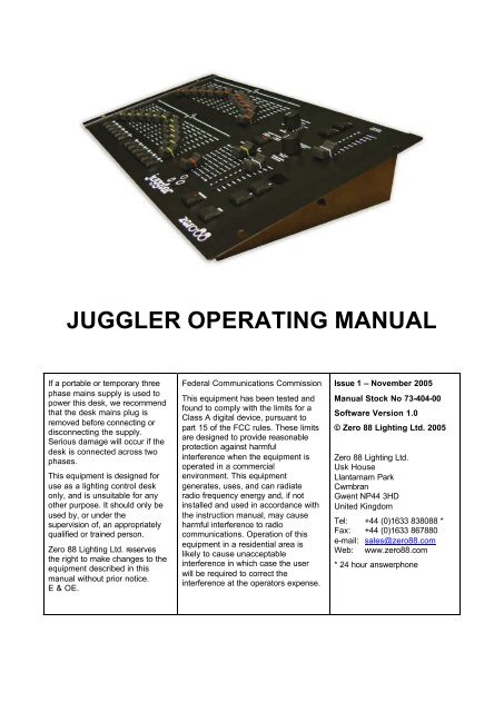
<strong>JUGGLER</strong> <strong>OPERATING</strong> <strong>MANUAL</strong>If a portable or temporary threephase mains supply is used topower this desk, we recommendthat the desk mains plug isremoved before connecting ordisconnecting the supply.Serious damage will occur if thedesk is connected across twophases.This equipment is designed foruse as a lighting control deskonly, and is unsuitable for anyother purpose. It should only beused by, or under thesupervision of, an appropriatelyqualified or trained person.Zero 88 Lighting Ltd. reservesthe right to make changes to theequipment described in thismanual without prior notice.E & OE.Federal Communications CommissionThis equipment has been tested andfound to comply with the limits for aClass A digital device, pursuant topart 15 of the FCC rules. These limitsare designed to provide reasonableprotection against harmfulinterference when the equipment isoperated in a commercialenvironment. This equipmentgenerates, uses, and can radiateradio frequency energy and, if notinstalled and used in accordance withthe instruction manual, may causeharmful interference to radiocommunications. Operation of thisequipment in a residential area islikely to cause unacceptableinterference in which case the userwill be required to correct theinterference at the operators expense.Issue 1 – November 2005Manual Stock No 73-404-00Software Version 1.0© Zero 88 Lighting Ltd. 2005Zero 88 Lighting Ltd.Usk HouseLlantarnam ParkCwmbranGwent NP44 3HDUnited KingdomTel: +44 (0)1633 838088 *Fax: +44 (0)1633 867880e-mail: sales@zero88.comWeb: www.zero88.com* 24 hour answerphone
ContentsIntroduction .................................................................................................................................... 3This Manual.................................................................................................................................. 3The Juggler Lighting Desk ......................................................................................................... 3Preset Operation ........................................................................................................................... 4Introduction................................................................................................................................... 4Two Preset Operation................................................................................................................. 4Outputting Scenes....................................................................................................................... 4Manual Fades .............................................................................................................................. 5Timed Crossfades ....................................................................................................................... 5Flashing Channels ...................................................................................................................... 5Wide Mode Operation................................................................................................................. 6Storing and Outputting Scenes ................................................................................................. 6Manual and Timed Fades .......................................................................................................... 7Flashing Channels ...................................................................................................................... 7Sequences...................................................................................................................................... 8Introduction................................................................................................................................... 8Programming Sequences .......................................................................................................... 8Editing Sequences ...................................................................................................................... 9Playing Back Sequences .........................................................................................................10Manual Playback .......................................................................................................................10Automatic Playback ..................................................................................................................10Glossary ........................................................................................................................................11Technical Specification .............................................................................................................14External Power Supply.............................................................................................................14DMX Output................................................................................................................................14
IntroductionThis ManualThis manual describes the operation and programming of the Juggler lighting desk.Throughout this manual all references to controls, buttons and lights on the front panelappear in capital letters, eg GRAND MASTER, PRESET CONTROL, WIDE etc.The Juggler Lighting DeskThe Juggler lighting desk is a two preset 12 channel desk. The wide mode feature allowsa single preset 24 channel operation. Crossfades between scenes can be manual ortimed. Individual channels may be flashed.Up to 12 sequences of 99 steps each can be recorded on the desk. One sequence can beoutput at a time. The sequence can be played back manually or automatically at therequired speed.The output from the desk is DMX 512 only (channels 1-24).Juggler 73-404-00 Issue 1 Page 3
Preset OperationIntroductionThe Juggler desk can be operated as either two 12 channel presets controlling 12channels, or a single wide preset controlling 24 channels.In Two Preset operation, separate scenes are set up on PRESET A and PRESET Bfaders. The A MASTER and B MASTER faders are used to crossfade between the twodifferent scenes.In Wide Mode, the first scene is set up on the PRESET A and PRESET B faders and isstored temporarily using the PRESET CONTROL button. Once stored, another scene canbe set up on the PRESET A and PRESET B faders. The A MASTER and B MASTERfaders are then used to crossfade between the stored scene and the scene on thePRESET faders.In Two Preset and Wide Modes crossfades between scenes can be manual or timed.Overall output is under the control of the GRAND MASTER fader.Two Preset OperationThe PRESET A and PRESET B faders, the A MASTER and B MASTER faders and theGRAND MASTER fader are used to control the output levels from the desk. The FADETIME control is used to determine the crossfade time between scenes.Outputting ScenesTo Output a Scene from Preset A - Set the required levels for each channel on thePRESET A faders. Set the A MASTER to full and the B MASTER to zero. The scene setup on PRESET A is output live.To Output a Scene from Preset B - Set the required levels for each channel on thePRESET B faders. Set the A MASTER to zero and the B MASTER to full. The scene setup on PRESET B is output live.Page 4 Juggler 73-404-00 Issue 1
Manual FadesEnsure the FADE TIME control is set to Manual. Set up a scene using the PRESET Afaders. Set up a different scene on the PRESET B faders.Set the A MASTER to full, and the B MASTER to zero. The scene set on the PRESET Afaders is output.To crossfade to the scene set up on PRESET B, simultaneously move the A MASTER tozero and the B MASTER to full. You have direct control over the speed of the scenechange. As the two master faders are moved in tandem the scene set up on PRESET Bwill fade in and the scene set on PRESET A will fade out.A new scene can then be set up on PRESET A without affecting the outputs.To crossfade to the new scene on PRESET A, simultaneously move the A MASTER to fulland the B MASTER to zero.As the two master faders are moved in tandem the scene set up on PRESET B will fadeout and the scene set on PRESET A will fade in.Timed CrossfadesSet the A MASTER and B MASTER faders to zero. Set up a scene using the PRESET Afaders. Set up a different scene on the PRESET B faders.Set the FADE TIME control to the required crossfade time.Quickly move the A MASTER fader to full. The scene on the PRESET A faders will fade inand be output live. The time taken for the fade to complete is determined by the value seton the FADE TIME control.To crossfade to the scene on PRESET B, quickly move the A MASTER fader to zero andthe B MASTER fader to full. The scene on PRESET B will fade in and the scene onPRESET A will fade out in the selected time. While the crossfade is in progress the LEDsin the PRESET CONTROL button flash. They go out when the fade is complete.A new scene can then be set up on PRESET A without affecting the outputs.To crossfade to the scene on PRESET A, quickly move the A MASTER to full and the BMASTER to zero. The scene on PRESET A will fade in and the scene on PRESET B willfade out in the selected time.Flashing ChannelsEnsure that the flash function is active (LED in FLASH button is on).Press and hold down an individual CHANNEL FLASH button. The channel is then addedto the scene at the level set on the GRAND MASTER.Release the CHANNEL FLASH button. The channel returns to its previous level.Juggler 73-404-00 Issue 1 Page 5
Wide Mode OperationIn Wide Mode you are able to crossfade between, or combine two scenes which are 24channels wide.A scene is set up using both the PRESET A and PRESET B faders (PRESET A faderscontrol channels 1 -12, PRESET B faders control channels 13 - 24). This scene is thenstored temporarily by pressing the PRESET CONTROL button.A second scene can then be set up on the PRESET A and PRESET B faders. The AMASTER and B MASTER faders can then be used to crossfade between the two scenes.The PRESET CONTROL button is used to control which of the master faders has controlof the PRESET channel faders and the stored scene. The GRAND MASTER is used tocontrol the final output levels from the desk. The FADE TIME control is used to determinethe crossfade time between the two scenes.Storing and Outputting ScenesEnsure that the desk is in Wide Mode (LED in WIDE button is on). On first entering WideMode or re-entering Wide Mode, the PRESET faders will be assigned to the A MASTER,and the stored scene assigned to the B MASTER. The lights in the PRESET CONTROLbutton indicate this (A FADERS, B STORED).Set the A MASTER and GRAND MASTER faders to full and the B MASTER fader to zero.Ensure that the lights in the PRESET CONTROL button indicate A FADERS, B STOREDSet up a scene using the PRESET A and PRESET B faders. This scene will be output.To store the scene press the PRESET CONTROL button. The output levels aretemporarily stored and the lights in the PRESET CONTROL button change to B FADERS,A STORED. The A MASTER is now assigned to the stored scene and the B MASTERassigned to the PRESET faders, so the outputs remain the same.Set up the next scene using the PRESET A and PRESET B faders. The outputs are notaffected since the B MASTER is currently at zero.To crossfade between the stored scene and the scene on the PRESET faders,simultaneously move the A MASTER to zero and the B MASTER to full.Press the PRESET CONTROL button. The output levels are saved into the temporarystore (overwriting the previous values) and the lights in the PRESET CONTROL buttonchange to indicate A FADERS, B STORED. The B MASTER is now assigned to the storedscene and the A MASTER to the PRESET faders, so the outputs remain the same.Repeat the operations described above to set up a new scene on the preset faders,crossfade to the new scene, and save it to a temporary store etc..Page 6 Juggler 73-404-00 Issue 1
Manual and Timed FadesCrossfading between the scene set up on the preset faders and the stored scene isachieved by moving the A MASTER and B MASTER faders in tandem.If the FADE TIME control is set to Manual, the crossfade time is determined by the speedat which the A MASTER and B MASTER faders are moved. The operator has directcontrol over the speed of the scene change.If the FADE TIME control is not set to manual, the crossfade time will be the time indicatedon the front panel of the desk. While a timed crossfade is in progress using the A and BMASTER faders, the LEDs in the PRESET CONTROL button flash.Flashing ChannelsUse the FLASH button to select the required flash mode as follows:When the LED in the FLASH button is off - the CHANNEL FLASH buttons are disabled.When the LED in the FLASH button is on - the CHANNEL FLASH buttons will flashchannels 1-12.When the LED in the FLASH button is flashing - the CHANNEL FLASH buttons will flashchannels 13-24.Press and hold down an individual CHANNEL FLASH button. The channel is then addedto the scene at the level set on the GRAND MASTER.Release the CHANNEL FLASH button. The channel returns to its previous level.Juggler 73-404-00 Issue 1 Page 7
SequencesIntroductionA sequence is a series of up to 99 states which are stored in the desk and can be playedback sequentially. Up to 12 sequences may be programmed and stored on the Juggler.Only one programmed sequence may be played back at a time. A sequence can beplayed back manually or automatically. Transitions between the steps can be snap or fade.The SEQUENCE MASTER fader controls the maximum output level of the sequence.The LED in the SEQUENCE button indicates the ‘mode’ as follows:Off = No Sequence Running On = Program Mode Flashing = Playback ModeThe seven segment display shows the selected step number in the sequence. When theSHIFT key is held down the seven segment display shows the sequence number. The UPand DOWN buttons are used to change the selected step or sequence number.If no sequence is being output the seven segment display shows “—“ as an indication thatthe desk is powered (there is no separate power LED on the desk).Programming SequencesTo enter Program Mode – hold down the SEQUENCE button for about two seconds. TheLED in the SEQUENCE button comes on.Hold down the SHIFT button and use the UP and DOWN buttons to select the requiredsequence number (1 – 12). Release the SHIFT button. The seven segment display nowindicates the step number.Use the UP and DOWN buttons to select the required step number ( 1 – 99).Use the PRESET A and PRESET B faders to set up the required output levels for the step.Press the SEQUENCE button to program the selected step. The selected step willautomatically increment to the next step and the LED in the SEQUENCE button will flashmomentarily to indicate that the step was programmed.Repeat the above procedure for each step to be programmed in the sequence.Set the SEQUENCE SPEED and FADE TIME controls to the required values for thesequence.To exit Program Mode hold down the SEQUENCE button for about two seconds.The desk returns to Playback Mode and the last selected sequence is started and output.Page 8 Juggler 73-404-00 Issue 1
Editing SequencesHold down the SEQUENCE button for about two seconds to enter Program Mode. TheLED in the SEQUENCE button comes on.Hold down the SHIFT button and use the UP and DOWN buttons to select the requiredsequence number to edit. Release the SHIFT button. The seven segment display nowindicates the step number.Use the UP and DOWN buttons to select the required step number.To program a new step – Use the PRESET A and PRESET B faders to set up therequired output levels for the step. Press the SEQUENCE button to program the step.To edit a programmed step – Use the PRESET A and PRESET B faders to set up therequired output levels for the step. Note that the PRESET CHANNEL faders must bemoved to their programmed levels before they become active. Press the SEQUENCEbutton to re-program the step.To clear a step – Hold down the SHIFT button and press the SEQUENCE button.To clear all the steps in the sequence – Hold down the SHIFT button and press andhold down the SEQUENCE button for about two seconds.Notes – Programming and Editing SequencesAny of the 12 programmable sequences can be selected by holding down the SHIFTbutton and using the UP and DOWN buttons or by holding down the SHIFT button andpressing one of the CHANNEL FLASH buttons.Holding down the SHIFT button and pressing the UP and DOWN buttons together selectssequence 1.If the selected sequence is unprogrammed a dot is displayed after the sequence number.Any of the 99 steps can be selected using the UP and DOWN buttons.Pressing the UP and DOWN buttons together selects step 1.If the selected step is unprogrammed a dot is displayed after the step number.For unprogrammed steps, the PRESET CHANNEL faders are immediately active.For programmed steps, the programmed levels are output and the PRESET CHANNELfaders must be moved to their programmed levels before they become active.Juggler 73-404-00 Issue 1 Page 9
Playing Back SequencesThe simplest way to play back a programmed sequence is to hold down the SHIFT buttonand press the CHANNEL FLASH button corresponding to the sequence number (1 – 12).Alternatively, you can press the SEQUENCE button to enter Playback mode. The lastselected sequence is started. To select a different sequence to be output - hold down theSHIFT key and use the UP and DOWN buttons to select the required sequence number.The FADE TIME and SEQUENCE SPEED controls are then used to determine how theselected sequence is output as described below.Press and hold down the SEQUENCE button for about two seconds to stop the sequence.Manual PlaybackSet the SEQUENCE SPEED control to Manual.Use the UP and DOWN buttons to select the step to be output (if different to the oneindicated by the seven segment display)Press the SEQUENCE button to output the selected step. The selected step willautomatically increment to the next programmed step in the sequence.Use the FADE TIME control to determine whether the outputs snap to their programmedlevels or fade to them.Automatic PlaybackSet the SEQUENCE SPEED control to the required speed.Use the FADE TIME control to determine whether the outputs snap to their programmedlevels or fade to them.Notes – Playing Back SequencesIf no sequence is being output, then the 7-segment display will show ‘--' as an indicationthat the desk is powered (since there is no separate power LED).Only programmed sequences can be selected and output.In Manual Playback only programmed steps can be selected.Pressing the UP and DOWN buttons together resets the selected step to the firstprogrammed step in the sequence.If the selected step is the current step, then a dot is displayed after the step number.All 24 programmed channels are played back regardless of the Wide setting on the desk.The settings of the SEQUENCE SPEED and FADE TIME controls are stored for thesequence when it is programmed, but they can be overridden live when playing back thesequence. The controls must be moved to their stored settings before they become active.Page 10 Juggler 73-404-00 Issue 1
GlossaryA MasterAnalogueB MasterBumpBump ButtonCEChannelChannel FlashCrossfadeDemuxDeskDimmerDiplessDMX-512The A MASTER fader controls the maximum output level from thePRESET A faders. In wide mode, this fader controls the maximumoutput level from all 24 preset channel faders or the stored scene.A control standard which existed before the invention of DMX. 10 Voltcontrol signals provide the dimmer with level information. DMX canbe converted to Analogue via the use of a Demux.The B MASTER fader controls the maximum output level from thePRESET B faders. In wide mode, this fader controls the maximumoutput level from all 24 preset channel faders or the stored scene.The B MASTER fader is reversed to facilitate crossfades whenmoving the A MASTER and B MASTER faders in tandem.The American term for Flash.The American term for a Flash Button.Conformité Européenne – A European product standard, displayed onall products on sale in the EU.A term used to describe a single fader controlling a single light.Dimmers may have 6, 12, 24 or 48 channels. The Juggler can controleither 12 or 24 channels (wide mode).The CHANNEL FLASH buttons are used to flash individual channelsto the level of the GRAND MASTER fader. The actual channelsflashed are determined by the FLASH button.A transition between one scene and another, over a pre-defined time.A device which splits a DMX signal into analogue control signals, foruse with older generation dimmers.A commonly used name for the lighting control equipment. Alsosometimes known as Board or Console.A device which takes a control signal and turns it into a dimmed mainsvoltage for controlling the brightness of a standard filament lamp.The fades on the Juggler are dipless, ie there will not be a ‘dip’ in thebrightness on stage when crossfading from one scene to another.Standard communications protocol for dimmers and moving heads.512 channels of control are digitally multiplexed and sent down acable to dimmers, which listen for their specific data, according to theirstart address.Juggler 73-404-00 Issue 1 Page 11
Fade TimeFaderFCCFlash ButtonThe FADE TIME control determines the crossfade time between thepresets A and B in Two Preset Mode or between the preset scene andthe stored scene in Wide Mode.A fader is used to control the intensity of a light. In addition to thePRESET CHANNEL faders, the Juggler has faders to control theoverall output (GRAND MASTER), sequence output (SEQUENCEMASTER), and the level of the A and B presets (A MASTER, BMASTER). The faders on the Juggler can have any position from 0 to100%. A fader is sometimes referred to as a Slider.Federal Communications Commission. The US equivalent of CE.The FLASH button determines the operation of the CHANNEL FLASHbuttons on the desk (disabled, channels 1-12 or channels 13-24).Grand MasterHTPIEC320-C14IntensityKeyLawLEDOutputPatchPotPreset A FadersThe GRAND MASTER fader controls the overall output of the desk.Highest Takes Precedence. The mixing method used on the Juggler.The various brightness sources (A Preset, B Preset, Channel Flashbuttons and Sequence) are mixed on a HTP basis.The type of mains input connector on the inline PSU, sometimesshortened to simply IEC, or referred to as a kettle plug.How bright a light is. Also known as Dimmer.Another name for a Button.The curve of the dimmer, which is normally set on the dimmer itself.The Juggler does not allow you to control the fade law.Light Emitting Diode. A small electrical component which emits lightwhen a current is passed through it in a particular direction. These areused on certain Juggler buttons to indicate selections or presses.A single desk channel, which is controlled by the Juggler.The Juggler desk has a fixed patch. Channels 1 - 24 are patched toDMX output channels 1 – 24.A potentiometer, which can be turned to set various values in a givenrange. The two Pots on the Juggler desk are the FADE TIME andSEQUENCE SPEED controls.The PRESET A faders control the output levels of channels 1 – 12 inassociation with the A MASTER and GRAND MASTER faders.Preset B Faders The PRESET B faders control the output levels of channels 1 – 12(two preset mode) or channels 13 – 24 (Wide Mode) in associationwith the B MASTER and GRAND MASTER faders.Preset ControlThe PRESET CONTROL button is only applicable in Wide Mode. ThePRESET CONTROL button and the accompanying LEDs are used tocontrol and indicate which master (A MASTER or B MASTER) hascontrol of the preset channel faders, and which master has control ofthe ‘stored’ scene. While a timed crossfade is in progress the LED(s)in the PRESET CONTROL button flash.Page 12 Juggler 73-404-00 Issue 1
PSURateSequencePower Supply Unit. The external box of electronics which alter thesupplied power voltage into the correct settings for the Juggler.Another name for Speed. How fast a sequence is running.A sequence is a series of up to 99 states which are played backsequentially. A programmed sequence can be played back manuallyor automatically. Up to 12 different sequences may be programmedon the Juggler desk.Sequence Button The SEQUENCE Button has several functions depending on theoperating mode (see Sequence section for further details).Sequence Master The SEQUENCE MASTER fader is used to control the maximumoutput level from the sequence during playback.Sequence Speed The SEQUENCE SPEED control is used for setting the speed ofsequences on the Juggler. When the control is set to Manual, thesequence is only advanced when the SEQUENCE Button is pressed.Seven SegmentShift ButtonSliderSnapSpeed PotTerminatorThe Seven Segment display shows the step number in the currentsequence or the sequence number if the SHIFT button is held down.The SHIFT button has a number of functions relating to Sequences(see Sequence section for further details).See Fader.A fade which happens instantly.See Sequence Speed control.A 120? ½ Watt resistor soldered between pins 2+3 of a male XLR,which provides protection against signal ‘bounce’. This should beplaced at the end of a DMX signal chain.Up/Down Buttons The UP and DOWN buttons below the seven segment display areused to select the sequence number or step number.Wide ButtonX-fadeXLRZero 88The WIDE button is used to switch the desk between two presetoperation (12 channel) or wide mode operation (24 channel).Another name for Crossfade. A fade from one scene to another.The connector range used for the DMX output and Power connectorson the back of the Juggler. There are various different XLRconnectors available, primarily 3-pin (used for Audio and some cheapDMX devices), 4-pin (used for power and colour scrollers) and 5-pin(used for DMX devices). Note that you should never connect a devicewith a 4 pin XLR to any other device unless they were built to be usedtogether. Different manufacturers use different voltages on thesepins, and misuse could result in damage to one or both devices.The manufacturer of the Juggler desk.Juggler 73-404-00 Issue 1 Page 13
Technical SpecificationExternal Power SupplyIn-line external power supply.Mains voltage 90-253V, 47-63Hz (CEE22 inlet).Power consumption < 20W.4 pin male XLR connector on desk:Connector Pin Number Power1 0V2 +5V DC @200mA3 +12V DC (not used by desk)4 Not ConnectedShellGNDDMX Output5 pin female XLR, unisolated with voltage protection.Data on DMX channels 1-24 only.DMX-RDM Hardware Ready.Connector Pin Number DMX Output1 Signal Ground (0V)2 DMX Drive Complement (1-)3 DMX Drive True (1+)4 Not Connected5 Not ConnectedPage 14 Juggler 73-404-00 Issue 1
Zero 88 Lighting Ltd.Usk HouseLlantarnam ParkCwmbranGwent NP44 3HDTel: +44 (0)1633 838088Fax: +44 (0)1633 867880email: sales@zero88.comWeb: www.zero88.com