Installation and Maintenance Manual - Hytrol Conveyor Company
Installation and Maintenance Manual - Hytrol Conveyor Company
Installation and Maintenance Manual - Hytrol Conveyor Company

You also want an ePaper? Increase the reach of your titles
YUMPU automatically turns print PDFs into web optimized ePapers that Google loves.
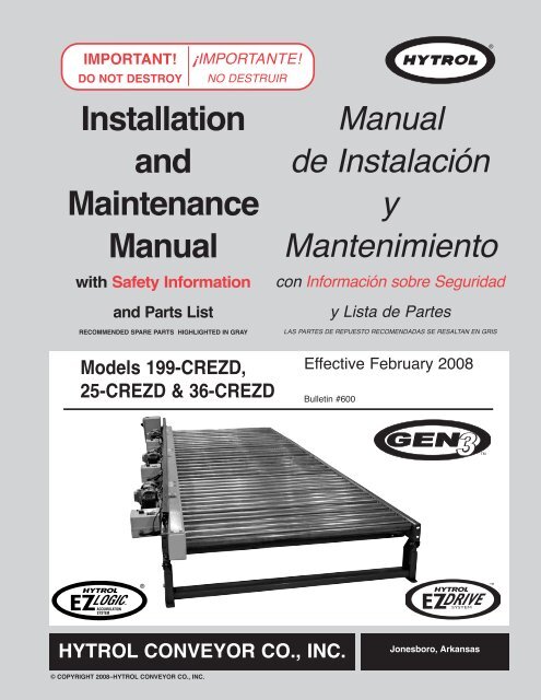
IMPORTANT!DO NOT DESTROY¡IMPORTANTE!NO DESTRUIR<strong>Installation</strong><strong>and</strong><strong>Maintenance</strong><strong>Manual</strong>with Safety Information<strong>and</strong> Parts ListRECOMMENDED SPARE PARTS HIGHLIGHTED IN GRAY<strong>Manual</strong>de InstalaciónyMantenimientocon Información sobre Seguridady Lista de PartesLAS PARTES DE REPUESTO RECOMENDADAS SE RESALTAN EN GRISModels 199-CREZD,25-CREZD & 36-CREZDEffective February 2008Bulletin #600TMDRIVESYSTEMHYTROL CONVEYOR CO., INC.Jonesboro, Arkansas© COPYRIGHT 2008–HYTROL CONVEYOR CO., INC.
● Table of ContentsWarning Signs . . . . . . . . . . . . . . . . . . . . .3INTRODUCTIONReceiving <strong>and</strong> Uncrating . . . . . . . . . . . . .4INSTALLATION<strong>Installation</strong> Safety Precautions . . . . . . . .5Support <strong>Installation</strong> . . . . . . . . . . . . . . . . .6<strong>Conveyor</strong> Set-Up . . . . . . . . . . . . . . . . . . .8Electrical Equipment . . . . . . . . . . . . . . .10Sequence of Operation . . . . . . . . . . . . .12EZLogic® System . . . . . . . . . . . . . . . . .14EZDrive Zone Starter Box . . . . . . . . .16Loading Applications . . . . . . . . . . . . . . .18Unloading Applications . . . . . . . . . . . . .21OPERATIONOperation Safety Precautions . . . . . . . .24<strong>Conveyor</strong> Start-Up . . . . . . . . . . . . . . . .25MAINTENANCE<strong>Maintenance</strong> Safety Precautions . . . . .26Lubrication . . . . . . . . . . . . . . . . . . . . . . .27Trouble Shooting . . . . . . . . . . . . . . . . . .28<strong>Maintenance</strong> Checklist . . . . . . . . . . . . .30How To Order Replacement Parts . . . .30REPLACEMENT PARTSModel 199-CREZD Parts Drawing . . . .32Model 199-CREZD Parts List . . . . . . . .34Model 25-CREZD Parts Drawing . . . . .35Model 25-CREZD Parts List . . . . . . . . .37Model 36-CREZD Parts Drawing . . . . .38Model 36-CREZD Parts List . . . . . . . . .40● Tabla de ContenidoSeñales de Advertencia . . . . . . . . . . . . .3INTRODUCCIONRecepción y Desembalaje . . . . . . . . . . .4INSTALACIONMedidas de SeguridadAl Instalar . . . . . . . . . . . . . . . . . . . . . .5Instalación de los Soportes . . . . . . . . . . .6Montaje del Transportador . . . . . . . . . . .8Equipo Eléctrico . . . . . . . . . . . . . . . . . .10Secuencia de Operación . . . . . . . . . . . .12Sistema EZLogic® . . . . . . . . . . . . . . . .14Motor Controlador EZDrive . . . . . . . .16Aplicaciones de Carga . . . . . . . . . . . . .18Aplicaciones de Descarga . . . . . . . . . .21OPERACIONMedidas de Seguridad . . . . . . . . . . . . .24Arranque del Transportador . . . . . . . . .25MANTENIMIENTOMedidas de Seguridad . . . . . . . . . . . . .26Lubricación . . . . . . . . . . . . . . . . . . . . . .27Resolviendo Problemas . . . . . . . . . . . .29Lista del Plan de Mantenimiento . . . . .31Como Ordenar Partes de Repuesto . . .31PARTES DE REPUESTOModelo 199-CREZD Dibujo de Partes .32Modelo 199-CREZDLista de Partes . . . . . . . . . . . . . . . . . .34Modelo 25-CREZD Dibujo de Partes . .35Modelo 25-CREZDLista de Partes . . . . . . . . . . . . . . . . . .37Modelo 36-CREZD Dibujo de Partes . .38Modelo 36-CREZDLista de Partes . . . . . . . . . . . . . . . . . .402
COLOCAR LAS MANOS SOBRE O DENTRO DEL TRANSPORTADORCUANDO ESTE EN FUNCIONAMIENTOPOLEAS DEL TRANSPORTADOR MIENTRAS ESTE EN FUNCIONAMIENTOES RESPONSABILIDAD DE LOS SUPERVISORES IMPLEMENTAR LAS SEÑALESANTERIORES Y TAMBIEN PROVEER LA ADECUADA PROTECCION PARACUALQUIER USO, OPERACION O SERVICIO PARTICULAR.● Warning SignsIn an effort to reduce the possibility of injury to personnelworking around HYTROL conveying equipment, warningsigns are placed at various points on the equipment to alertthem of potential dangers. Please check equipment <strong>and</strong>note all warning signs. Make certain your personnel arealerted to <strong>and</strong> obey these warnings. Shown below are typicalsigns that are attached to this equipment.● Señales de AdvertenciaEn un esfuerzo por reducir la posibilidad de accidentes alpersonal trabaj<strong>and</strong>o junto al equipo de transportaciónHYTROL, se colocan señales de advertencia en diferentespuntos del equipo para alertarlos de riesgos potenciales.Por favor verifique el equipo y asegúrese de ver todas lasseñales de advertencia. Asegúrese de que su personal estéalerta y obedezca las señales. Abajo se muestran lasseñales que se encuentran en este equipo.WARNING!DO NOT START CONVEYORUNTIL PERSONNEL ARE CLEARPLACED ON ALL POWERED CONVEYORSNEAR DRIVE AND/OR CONTROLS.COLOCADA EN TODOS LOSTRANSPORTADORES MOTORIZADOSCERCA AL MOTOR Y/O LOS CONTROLESWARNINGServicing moving orenergized equipmentcan cause severe injuryLOCK OUT POWERbefore removing guardPLACED NEXT TO DRIVE, BOTH SIDES.COLOCADA JUNTO A LA UNIDAD MOTRIZ, ENAMBOS LADOS.DANGERClimbing, sitting,walking or riding onconveyor at any timewill cause severeinjury or deathKEEP OFFPLACED ON 20 FT. INTERVALS,BOTH SIDES.COLOCADA EN INTERVALOS DE 20 PIES, A AMBOS LADOS.WARNINGExposed movingparts can causesevere injuryLOCK OUT POWERbefore removingguardPLACED ON ALL CHAIN GUARDS.COLOCADA EN TODAS LAS GUARDA CADENAS.WARNINGEquipment startsautomatically -can cause severeinjuryKEEP AWAYPLACED NEXT TO DRIVE, BOTH SIDES.COLOCADA JUNTO A LA UNIDAD MOTRIZ, ENAMBOS LADOS.WARNINGMoving equipmentcan cause severeinjuryKEEP AWAYPLACED ON TERMINATING ENDS.COLOCADA EN LOS EXTREMOS.DANGERHazardous voltagewill cause severeinjury or death.LOCK OUT POWERbefore servicing.PLACED AT ALL ZONE BOXESCOLOCADA EN TODAS LAS ZONAS CONMOTORWARNINGNEVER... START CONVEYOR UNTIL PERSONNEL ARE CLEARNEVER... LUBRICATE OR REPAIR WHILE CONVEYOR IS RUNNINGNEVER... RUN THE CONVEYOR WITH GUARDS REMOVEDPUT YOUR HANDS ON THE CONVEYOR OR IN THENEVER...CONVEYOR WHEN IT IS RUNNING.NEVER... ALLOW ANY PART OF YOUR BODY TO COME IN CONTACTWITH THE CONVEYOR PULLEYS WHILE IT IS RUNNING.IT IS THE EMPLOYERS RESPONSIBILITY TO IMPLEMENT THE ABOVE ANDALSO TO PROVIDE ADEQUATE PROTECTION FOR ANY PARTICULAR USE,OPERATION OR SERVICE.DO NOT REMOVE THIS SIGN FROM THIS MACHINEPLACED AT DRIVE OF ALL POWERED CONVEYORS.COLOCADA EN LA UNIDAD MOTRIZ DE TODOS LOSTRANSPORTADORES MOTORIZADOS.NOTE: BILINGUAL (SPANISH) LABELS AVAILABLE UPON REQUEST.NOTA: ETIQUETAS BILINGÜES (ESPAÑOL) SERÁN PROVEÍDASBAJO PETICIÓN.PELIGRO!Este equipo arrancaautomáticamente –Puede causar lesionesgraves.No se acerque.ADVERTENCIA!Partes expuestas enmovimento puedencausar lesiones graves.DESCONECTAR laenergia antes deremover la guarda.ADVERTENCIA!El mantenimiento departes eléctricas o enmovimiento puedecausar lesiones graves.DESCONECTAR la energiaantes de remover la guarda.ADVERTENCIA!Partes en movimientopueden causarlesiones graves.NO SE ACERQUEPELIGRO!Subirse, ? sentarse,caminar o viajaren el transportadoren cualquier momento,puede causar lesionesgraves o incluso la muerte.CONSERVE DISTANCIAPELIGRO!El alto voltaje puede causarlesiones o la muerte.Desconecte la energía antesde realizar mantenimiento.¡ADVERTENCIA!NO PONER EN MARCHA EL TRANSPORTADORHASTA QUE TODO EL PERSONAL ESTE ALEJADOADVERTENCIANUNCA.. ARRANCAR EL TRANSPORTADOR HASTA QUE TODO EL PERSONAL ESTE ALEJADONUNCA.. LUBRICAR O REPARAR MIENTRAS EL TRANSPORTADOR ESTE EN FUNCIONAMIENTONUNCA.. HACER FUNCIONAR EL TRANSPORTADOR CON LAS GUARDAS REMOVIDASNUNCA..NUNCA.. PERMITIR QUE ALGUNA PARTE DEL CUERPO ESTE EN CONTACTO CON LASNO REMUEVA ESTA SEÑAL DE LA MAQUINA3
INTRODUCTIONThis manual provides guidelines <strong>and</strong> procedures forinstalling, operating, <strong>and</strong> maintaining your conveyor. A completeparts list is provided with recommended spare partshighlighted in gray. Important safety information is also providedthroughout the manual. For safety to personnel <strong>and</strong>for proper operation of your conveyor, it is recommendedthat you read <strong>and</strong> follow the instructions provided in thismanual.INTRODUCCIONEste manual provee las pautas y los procedimientos parainstalar, operar y mantener su transportador. Se proporcionauna lista completa de partes, con partes de repuestorecomendadas que se resaltan en gris. También se proporcionainformación importante de seguridad a lo largo deeste manual. Para seguridad del personal y para un funcionamientoapropiado del transportador, se recomiendaque lean y sigan las instrucciones proporcionadas en estemanual.● Receiving <strong>and</strong>Uncrating1. . . Check the number of items received against the bill oflading.2. . . Examine condition of equipment to determine if anydamage occurred during shipment.3. . . Move all crates to area of installation.4. . . Remove crating <strong>and</strong> check for optional equipmentthat may be fastened to the conveyor. Make surethese parts (or any foreign pieces) are removed.● Recepción y Desembalaje1. . . Verifique el número de partes recibidas con respecto alconocimiento de embarque.2. . . Examine las condiciones del equipo con el fin de determinarsi algún daño ha ocurrido durante el transporte.3. . . Traslade todo el equipo al área de instalación.4. . . Remueva todos los empaques y verifique si hay partesopcionales que puedan estar atadas al equipo.Asegúrese de que estas partes (u otras partes externas)sean removidas.NOTE: If damage has occurred or freight is missing, seethe “Important Notice” attached to the crate.NOTA: Si algún daño ha ocurrido o falta cargamento,vea las “Notas Importantes” adheridas al embalaje.4
INSTALLATION● <strong>Installation</strong> Safety Precautionsfor <strong>Conveyor</strong>s <strong>and</strong>Related EquipmentGUARDS AND GUARDINGInterfacing of Equipment. When two or more pieces ofequipment are interfaced, special attention shall be given tothe interfaced area to insure the presence of adequateguarding <strong>and</strong> safety devices.Guarding Exceptions. Wherever conditions prevail thatwould require guarding under these st<strong>and</strong>ards, but suchguarding would render the conveyor unusable, prominentwarning means shall be provided in the area or on theequipment in lieu of guarding.Guarded by Location or Position. Where necessary forthe protection of employees from hazards, all exposed movingmachinery parts that present a hazard to employees attheir work station shall be mechanically or electrically guarded,or guarded by location or position.When a conveyor passes over a walkway, roadway, orwork station, it is considered guarded solely by location orposition if all moving parts are at least 8 ft. (2.44 m) abovethe floor or walking surface or are otherwise located so thatthe employee cannot inadvertently come in contact withhazardous moving parts.Although overhead conveyors may be guarded by location,spill guard, pan guards, or equivalent shall be providedif the product may fall off the conveyor for any reason <strong>and</strong> ifpersonnel would be endangered.HEADROOMWhen conveyors are installed above exit passageways,aisles, or corridors, there shall be provided a minimumclearance of 6 ft. 8 in. (2.032 m) measured vertically fromthe floor or walking surface to the lowest part of the conveyoror guards.Where system function will be impaired by providing theminimum clearance of 6 ft. 8 in. (2.032 m) through an emergencyexit, alternate passageways shall be provided.It is permissible to allow passage under conveyors with lessthan 6 ft. 8 in. (2.032 m) clearance from the floor for otherthan emergency exits if a suitable warning indicates lowheadroom.INSTALACION● Medidas de Seguridad al InstalarTransportadores y EquiposRelacionadosGUARDAS Y PROTECCIONESUnión del Equipo. Cu<strong>and</strong>o dos o más piezas del equipovan unidas, debe ponerse especial atención al área deunión para asegurar que las guardas adecuadas y los dispositivosde seguridad estén presentes.Excepciones de Protección. Dondequiera que lasguardas sean necesarias, pero que la colocación de lasmismas inhabilite el uso del transportador, se proporcionaránseñales de advertencia visibles en el área o en elequipo en vez de las guardas.Protección dada por Posición o Ubicación. Cu<strong>and</strong>o seanecesaria la protección de los empleados contra posiblesriesgos, todas las partes del equipo que estén expuestas yen movimiento, y que puedan presentar un peligro paraellos en sus puestos de trabajo, serán protegidas mecánicamenteo eléctricamente, o protegidas por su posición oubicación.Cu<strong>and</strong>o el transportador está instalado sobre pasillos,corredores o puestos de trabajo, se considera que está protegidoúnicamente por localización o posición si todas laspartes en movimiento están mínimo a 8 pies (2.44m) dealtura del piso, o si está localizado de tal manera que elempleado no pueda entrar en contacto inadvertidamentecon dichas partes.A pesar de que los transportadores aéreos pueden estarprotegidos por localización, guardas laterales e inferioresdeben ser proporcionadas para evitar que el producto secaiga del transportador y así mantener al personal fuera depeligro.UBICACION SUPERIORCu<strong>and</strong>o los transportadores son instalados sobre pasillos ocorredores de salida, debe dejarse un espacio libre demínimo 6 pies 8 pulgadas (2,032m), medido verticalmentedesde el piso o área de tránsito hasta la parte más baja deltransportador o de las guardas.Si se proporcionan señales de advertencia adecuadas indic<strong>and</strong>obaja altura, es posible dejar espacio libre con menosde 6 pies 8 pulgadas (2.032m) entre el piso y el transportadoren los pasillos que no sean salidas de emergencia.5
L● Support <strong>Installation</strong>1. . . Determine direction of product flow. Figure 6A indicatesthe flow as related to the EZLogic ® controls.2. . . Refer to “Match-Mark” numbers on ends of conveyorsections. (Figure 6A.) Position them in this sequencenear area of installation.3. . . Attach supports to all conveyor sections as shown inFigures 7A <strong>and</strong> 7B. H<strong>and</strong> tighten bolts only at thistime.4. . . Adjust elevation to required height.● Instalación de los Soportes1…Determine la dirección del flujo del producto. La Figura6A indica la dirección del flujo con relación a los controlesEZLogic®.2…Refiérase a las Etiquetas de Secuencia de Armadoubicadas al final de las secciones del transportador(Figura 6A). Posicione las secciones en esta secuenciacerca al área de instalación.3…Fije los soportes a todas las secciones de transportadorcomo se muestra en las figuras 7A y 7B. En estemomento, puede apretar los tornillos manualmente.4…Ajuste la elevación a la altura requerida.FIGURE 6AINFEED ZONE(ZONA DE ALIMENTACION)INTERMEDIATE ZONE(ZONA INTERMEDIA)DISCHARGE ZONE(ZONA DE DESCARGA)FLOWEZL OGIC®ZONE CONTROL ER(DIFFUSE SHOWN)(CONTROLADOR DE ZONA EZLOGIC®)[DIFUSO ES MOSTRADO]KNEE BRACE ANGLE(ANGULO DE SOPORTE)SUPPORTS(SOPORTES)MARK_______________________P-1CONVEYOR F.O.#_____________ 00001ITEM___________TO___________1 2MARK_______________________P-1CONVEYOR F.O.#_____________ 00001ITEM___________TO___________2 1HYTROL CONVEYOR CO. INC.JONESBORO, ARHYTROL CONVEYOR CO. INC.JONESBORO, AR"MATCH-MARK" NUMBERS(ETIQUETAS DE SECUENCIA DE ARMADO)6
FIGURE 7AADJUST TO DESIREDELEVATION(AJUSTE A LA ALTURADESEADA)INTERMEDIATESUPPORTS(SOPORTESINTERMEDIOS)SUPPORT(SOPORTE)FIGURE 7BMOUNTING BOLT(TORNILLO DE MONTAJE)BUTT COUPLINGS(PLACAS DE EMPALME)SIDE CHANNEL(CANAL LATERAL)SIDE CHANNELS(CANAL LATERAL)PIVOT PLATE(PLACA PIVOTE)STATIONARY SUPPORT(SOPORTE ESTACIONARIO)7
● <strong>Conveyor</strong> Set-Up1. . . Mark a chalk line on floor to locate center of the conveyor.2. . . Place the infeed section in position.3. . . Place remaining sections on extended support of previoussection.4. . . Fasten sections together with butt couplings <strong>and</strong>pivot plates (Figure 7B). H<strong>and</strong> tighten bolts only atthis time.5. . . Check to see that conveyor is level across width <strong>and</strong>length of unit. Adjust supports as necessary.6. . . Tighten all butt couplings <strong>and</strong> support mounting bolts<strong>and</strong> lag conveyor to floor.7. . . Connect EZLogic® cordset <strong>and</strong> EZDrive cable(Fig. 9A).8. . . Install electrical controls <strong>and</strong> wire disconnect panel(Figure 9B). The Dual Output Disconnect Panelrequires a 30 amp service <strong>and</strong> the Single Output DisconnectPanel requires a 15 amp service. All linesmust have proper Fuse or Breakers. See DisconnectPanel for required voltage.9. . . Connect IOP to EZLogic®. See EZLogic® GEN3Component <strong>Manual</strong> for more information about IOP.Note! All drive roller shafts are turned to within 10 thous<strong>and</strong>thsTIR (Total Indicator Runout). Some wobbling ofthe gearmotor may be noticeable <strong>and</strong> is typical in TorqueArm mounted gearmotors. This allows the gearmotor tofloat which prevents fatiguing of the drive shaft or prematurefailure of bearing components.● Montaje del Transportador1…Marque con tiza una línea en el suelo para ubicar el centrodel transportador.2…Coloque la sección de alimentación en su posición.3…Coloque las secciones restantes en la placa pivote delsoporte de la sección anterior.4…Asegure las secciones con placas de empalme y placaspivote (Figura 7B). Apriete los tornillos manualmente.5…Revise si el transportador esta nivelado a lo ancho ylargo de la unidad. Ajuste los soportes como sea necesario.6…Apriete las placas de empalme y los tornillos de montajedel soporte y ancle el transportador al piso.7…Conecte el cable del EZLogic® y el cable del EZDrive(Figura 9A).8…Instale los controles eléctricos y conecte el panel de control(Figura 9B). El panel de control de salida doblerequiere un servicio de 30 amperios. El panel de controlsencillo requiere un servicio de 15 amperios. Todas laslíneas deben tener fusibles o cortacircuitos apropiados.Vea el panel de control para el voltaje requerido.9…Conecte la IOP al EZLogic ® . Vea el manual de componentesde EZLogic® para mayor información acerca delIOP.Nota! Todos los ejes motrices rotan alrededor de diez milTIR (Total Indicador Runout). Puede llegarse a notar unbalanceo del gearmotor y es típico en gearmotors montadosen Brazos con Torque. Esto le permite al gearmotorflotar lo cual previene la fatiga del eje motriz o el desgasteprematuro de los componentes del rodamiento.8
FIGURE 9ADISCONNECT PANEL(PANEL DE CONTROL)208/230V3 PH. 60 HZ460V3 PH. 60 HZEZLOGIC® ZONE CONTROLLERWAKE UP EYE(MÓDULO DE ZONA EZLOGIC®OJO DESPERTADOR)EZLOGIC® ZONE CONTROLLER(MÓDULO DE ZONA EZLOGIC®)SINGLE OUTPUT(PANEL DE SALIDA SENCILLO)DUAL OUTPUT(PANEL DE SALIDA DOBLE)1-5 ZONES(1-5 ZONAS)6-10 ZONES(6-10 ZONAS)1-10 ZONES(1-10 ZONAS)11-20 ZONES(11-20 ZONAS)IOP(IOP)SINGLE OUTPUT DISCONNECT PANEL(PANEL PRINCIPAL DE SALIDA UNICA)ZONE GEARMOTOR(MOTOR EN ZONA)FLOWELECTRICAL END CAP(TAPON DE ULTIMACONEXION ELECTRICA)EZDRIVE ZONE STARTER BOX(CONTROLADOR DE ZONA EZDRIVE)EZLOGIC® ZONE CONTROLLERWAKE UP EYE(MÓDULO DE ZONA EZLOGIC®OJO DESPERTADOR)EZLOGIC® ZONE CONTROLLER(MÓDULO DE ZONA EZLOGIC®)IOP(IOP)ELECTRICAL END CAP(TAPON DE ULTIMACONEXION ELECTRICA)ZONE GEARMOTOR(MOTOR EN ZONA)ELECTRICAL END CAP(TAPON DE ULTIMACONEXION ELECTRICA)ZONE GEARMOTOR(MOTOR EN ZONA)DUAL OUTPUT DISCONNECT PANEL(MUST BE LOCATED AT THE CENTER OF CONVEYOR)PANEL DE SALIDA DOBLE CON FUENTE DE PODER(DEBE SER UBICADA EN EL CENTRO DEL TRANSPORTADOR)EZDRIVE ZONE STARTER BOX(CONTROLADOR DEZONA EZDRIVE)50 FT. MAXIMUM DISTANCE(SEE CHART FOR NUMBER OF ZONES)50 FT. DISTANCIA MÁXIMA(VER CUADRO PARA EL NÚMERO DE ZONAS)FIGURE 9BNOTE: CUSTOMER MUSTSUPPLY 15 AMP OR 30 AMPOVERCURRENT PROTEC-TION TO ALL DISCONNECTPANELS.15 AMP L1(L1)30 AMPL2(L2)L3(L3)L1(L1)L2(L2)L3(L3)(NOTA: EL CLIENTE DEBEPROVEER UNA PROTECCIÓNDE SOBRECARGA DE 14 AMPO 30 AMP A TODOS LOS PAN-ELES DE SALIDA)GROUND(CONEXION A TIERRA)15A BREAKER(DISYUNTOR DE 15A)GROUND(CONEXION A TIERRA)SINGLE OUTPUT DISCONNECT PANEL(PANEL PRINCIPAL DE SALIDA SENCILLO)DUAL OUTPUT DISCONNECT PANEL(PANEL PRINCIPAL DE SALIDA DOBLE)9
10● Electrical EquipmentWARNING!Electrical controls shall be installed <strong>and</strong> wired by aqualified electrician. Wiring information for the motor<strong>and</strong> controls are furnished by the equipment manufacturer.CONTROLSElectrical Code: All motor controls <strong>and</strong> wiring shall conformto the National Electrical Code (Article 670 or other applicablearticles) as published by the National Fire ProtectionAssociation <strong>and</strong> as approved by the American St<strong>and</strong>ardsInstitute, Inc.CONTROL STATIONSA) Control stations should be so arranged <strong>and</strong> located thatthe operation of the equipment is visible from them, <strong>and</strong>shall be clearly marked or labeled to indicate the functioncontrolled.B) A conveyor which would cause injury when started shallnot be started until employees in the area are alerted by asignal or by a designated person that the conveyor is aboutto start.When a conveyor would cause injury when started <strong>and</strong>is automatically controlled or must be controlled from aremote location, an audible device shall be provided whichcan be clearly heard at all points along the conveyor wherepersonnel may be present. The warning device shall beactuated by the controller device starting the conveyor <strong>and</strong>shall continue for a required period of time before the conveyorstarts. A flashing light or similar visual warning may beused in conjunction with or in place of the audible device ifmore effective in particular circumstances.Where system function would be seriously hindered oradversely affected by the required time delay or where theintent of the warning may be misinterpreted (i.e., a workarea with many different conveyors <strong>and</strong> allied devices),clear, concise, <strong>and</strong> legible warning shall be provided. Thewarning shall indicate that conveyors <strong>and</strong> allied equipmentmay be started at any time, that danger exists, <strong>and</strong> that personnelmust keep clear. The warnings shall be providedalong the conveyor at areas not guarded by position or location.C) Remotely <strong>and</strong> automatically controlled conveyors, <strong>and</strong>conveyors where operator stations are not manned or arebeyond voice <strong>and</strong> visual contact from drive areas, loadingareas, transfer points, <strong>and</strong> other potentially hazardous locationson the conveyor path not guarded by location, position,or guards, shall be furnished with emergency stop buttons,pull cords, limit switches, or similar emergency stopdevices.All such emergency stop devices shall be easily identifi-● Equipo Eléctrico¡ADVERTENCIA!Los controles eléctricos deben ser conectados e instaladospor un electricista calificado. La información sobreel cableado del motor y los controles será proporcionadapor el fabricante del equipo.CONTROLESCódigo Eléctrico: Todos los controles del motor y lasconexiones deben ajustarse al “National Electrical Code”(Artículo 670 u otros artículos aplicables) como fué publicadopor la “National Fire Protection Association” y aprobado por el“American St<strong>and</strong>ards Institute, Inc”.ESTACIONES DE CONTROLA) Las estaciones de control deberán estar arregladas y ubicadasen lugares donde el funcionamiento del equipo sea visibley deberán estar claramente marcadas o señaladas paraindicar la función controlada.B) Un transportador que pueda causar lesiones cu<strong>and</strong>o espuesto en marcha, no deberá ponerse en funcionamientohasta que los trabajadores en el área sean alertados por unaseñal o por una persona designada que indique que el transportadorestá a punto de arrancar.Cu<strong>and</strong>o un transportador pueda causar lesiones al arrancar yes controlado automáticamente o controlado desde una ubicaciónlejana, se deberá proporcionar un dispositivo sonoro elcual pueda ser escuchado claramente en todos los puntos a lolargo del transportador donde el personal pueda estar presente.El dispositivo de advertencia deberá ser activado por eldispositivo de arranque del transportador y deberá continuarson<strong>and</strong>o por un determinado periodo de tiempo antes de queel transportador empiece a funcionar. Una luz intermitente ouna advertencia visual similar puede ser utilizada con o enlugar del dispositivo sonoro si es más efectivo en circunstanciasparticulares.Cu<strong>and</strong>o el funcionamiento del sistema pueda ser seriamenteobstruído o adversamente afectado por el tiempo de retardorequerido, o cu<strong>and</strong>o el intento de advertencia pueda ser malinterpretado (ej., un área de trabajo con diversas líneas detransportadores y los dispositivos de advertencia relacionados),advertencias claras, concisas y legibles deben ser proporcionadas.Las advertencias deberán indicar que los transportadoresy los equipos relacionados pueden ser puestos enmarcha en cualquier momento, que existe un peligro y que elpersonal debe mantenerse alejado. Estas advertencias debenser proporcionadas a lo largo del transportador en áreas queno sean protegidas por la posición o la ubicación.C) Los transportadores controlados automáticamente o desdeestaciones lejanas, y los transportadores donde las estacionesde funcionamiento no estén controladas por una persona, oestén mas allá del alcance de la voz y del contacto visual de
able in the immediate vicinity of such locations unlessguarded by location, position, or guards. Where the design,function, <strong>and</strong> operation of such conveyor clearly is not hazardousto personnel, an emergency stop device is notrequired.The emergency stop device shall act directly on the controlof the conveyor concerned <strong>and</strong> shall not depend on thestopping of any other equipment. The emergency stopdevices shall be installed so that they cannot be overriddenfrom other locations.D) Inactive <strong>and</strong> unused actuators, controllers, <strong>and</strong> wiringshould be removed from control stations <strong>and</strong> panel boards,together with obsolete diagrams, indicators, control labels,<strong>and</strong> other material which serve to confuse the operator.SAFETY DEVICESA) All safety devices, including wiring of electrical safetydevices, shall be arranged to operate in a “Fail-Safe” manner,that is, if power failure or failure of the device itselfwould occur, a hazardous condition must not result.B) Emergency Stops <strong>and</strong> Restarts. <strong>Conveyor</strong> controls shallbe so arranged that, in case of emergency stop, manualreset or start at the location where the emergency stop wasinitiated, shall be required of the conveyor(s) <strong>and</strong> associatedequipment to resume operation.C) Before restarting a conveyor which has been stoppedbecause of an emergency, an inspection of the conveyorshall be made <strong>and</strong> the cause of the stoppage determined.The starting device shall be locked out before any attemptis made to remove the cause of stoppage, unless operationis necessary to determine the cause or to safely remove thestoppage.Refer to ANSI Z244.1-1982, American National St<strong>and</strong>ard forPersonnel Protection – Lockout/Tagout of Energy Sources –Minimum Safety Requirements <strong>and</strong> OSHA St<strong>and</strong>ard Number29 CFR 1910.147 “The Control of Hazardous Energy(Lockout/Tagout).”las áreas de conducción, áreas de carga, puntos de transferenciay otros sitios potencialmente peligrosos localizadosen la trayectoria del transportador que no tenga protecciónpor posición, ubicación o guardas, deberán ser equipadoscon interruptores, cordones o interruptores de límite o dispositivossimilares para paradas de emergencia.Todos estos dispositivos de parada de emergencia deberánser fácilmente identificables en las cercanías inmediatas alos puntos potencialmente peligrosos, a no ser que esténprotegidos por su ubicación, posición o protegidos conguardas. Donde el diseño, el funcionamiento, y la operaciónde tales transportadores no represente un claro peligro parael personal, un dispositivo de parada de emergencia no esnecesario.El dispositivo de parada de emergencia deberá actuar directamenteen el control del transportador concerniente y nodeberá depender de la parada de cualquier otro equipo. Losdispositivos de parada de emergencia deberán ser instaladosde tal forma que no puedan ser anulados desde otraslocalidades.D) Los dispositivos, controles desactivados o en desuso ylas conexiones, deberán ser removidos de las estaciones decontrol y de los tableros de m<strong>and</strong>o, junto con los diagramas,indicadores, etiquetas de control y otros materiales obsoletos,los cuales se prestan para confundir al operador.DISPOSITIVOS DE SEGURIDADA) Todos los dispositivos de seguridad, incluyendo la conexiónde dispositivos eléctricos, deben estar dispuestospara operar en una manera de “autoprotección”; es decir, sise presenta una pérdida de corriente o un fallo en el mismodispositivo, esto no debe resultar en una situación peligrosa.B) Paradas de Emergencia y Reactivadores. Los controlesdel transportador deberán estar dispuestos de tal maneraque, en caso de una parada de emergencia, se requiere unactivador o un arrancador manual en el lugar donde la paradade emergencia se presente para reanudar la operacióndel transportador o transportadores y el equipo asociado.C) Antes de reiniciar un transportador que ha sido detenidopor una emergencia, debe realizarse una revisión del transportadory determinarse la causa de la parada. El dispositivode arranque deberá ser bloqueado antes de intentar corregirel problema, a no ser que la operación del transportadorsea necesaria para determinar la causa de la parada opara solucionar el problema.Refiérase al ANSI Z244.1-1982, American National St<strong>and</strong>ardfor Personnel Protection - Lockout/Tagout of Energy Sources- Minimum Safety Requirements <strong>and</strong> OSHA St<strong>and</strong>ardNumber 29 CFR 1910.147 “The Control of HazardousEnergy (Lockout/Tagout).”11
● Sequence of OperationThe CREZD models are made up of a series of accumulationzones, each zone having an EZLogic® zone controller,an EZDrive zone starter box <strong>and</strong> a gearmotor. Thesequence of "loading" <strong>and</strong> "unloading" the conveyor is asfollows:LOADING THE CONVEYOR - SINGULATION MODE(Figure 13A)1. . . Beginning with the conveyor "empty," <strong>and</strong> the zonestop signal to the discharge zone controller"active,"(Refer to the “Auxiliary Connections” section,page 14.) a load placed on the conveyor continuesforward until it reaches the discharge zone (Zone #1).If two or more loads are placed on the conveyor witha space of less than one zone length between them,the loads will singulate (separate) during the first fewfeet of travel on the conveyor, until a space approximatelyequal to one zone length exists between allloads.2. . . When load #1 activates zone controller "A", Zone #1stops driving. A signal is sent to Zone #2 indicatingthat Zone #1 is occupied (Figure 13A).3. . . When load #2 activates zone controller "B", Zone #2stops driving. A signal is sent to Zone #3 indicatingthat Zone #2 is occupied.4. . . The above sequences are repeated until the conveyoris fully loaded.UNLOADING THE CONVEYOR - SINGULATION MODE1. . . Releasing load #1 is accomplished by "de-activating"the zone stop signal to the discharge zone (Refer tothe "Auxiliary Connections" section on page 14). Thisrestores power to the tread rollers in zone #1. Load#1 will then move forward, causing a gap betweenitself <strong>and</strong> load #2 (Figure 13B).2. . . When load #1 clears zone controller "A", load #2 willthen move forward, creating a gap between itself <strong>and</strong>load #3.3. . . This sequence will continue as long as the precedingload continues to move forward.● Secuencia de OperaciónLos modelos CREZD están compuestos por una serie dezonas de acumulación. Cada zona posee un módulo deacumulación EZLogic®, un motor controlador EZDrive yun gearmotor. La secuencia de "carga" y "descarga" deltransportador es como sigue:CARGANDO EL TRANSPORTADOR –SINGULATION MODE (Figura 13A)1. . . Empez<strong>and</strong>o con el transportador "vacío" y la señal deparo "activa" (Refiérase a la sección de “conexionesAuxiliares,” págiina 14.) en el módulo de la zona dedescarga, un primer producto puesto sobre el transportadorhará el recorrido hasta que llegue a la zonade descarga (Zona #1).Si dos o más productos se colocan sobre el transportadorcon un espacio de separación entre ellosmenor que la longitud de una zona, los productos sesepararán durante los primeros pies de recorrido enel transportador hasta que el espacio entre los productossea por lo menos igual a la longitud de unazona.2. . . Cu<strong>and</strong>o el producto #1 activa el módulo "A", la zona#1 se detiene completamente. Una señal es enviadaa la zona #2 indic<strong>and</strong>o que la zona #1 está ocupada(Figura 13A).3. . .4. . .Cu<strong>and</strong>o el producto #2 activa el módulo "B", la zona#2 se detiene completamente. Una señal es enviadaa la zona #3 indic<strong>and</strong>o que la zona #2 está ocupada.La secuencia anterior se repite hasta que el transportadoresté completamente cargado.DESCARGANDO EL TRANSPORTADOR –MODO DE SINGULACIÓN1. . . Se logra liberar el producto #1 "desactiv<strong>and</strong>o" laseñal de paro en la zona de descarga. (Refiérase ala sección “Conexiones de Paro de Zona” en la página14.) De esta forma se restablece la tracción enlos rodillos de paso en la zona #1. El producto #1 semoverá hacia adelante, caus<strong>and</strong>o un espacio entre simismo y el producto #2 (Figura 13B).2. . . Cu<strong>and</strong>o el producto #1 despeja el módulo "A", el producto#2 se moverá hacia adelante cre<strong>and</strong>o un espacioentre si mismo y el producto #3.3. . . Esta secuencia continuará mientras los productosprecedentes continúen moviéndose hacia adelante.12
FIGURE 13AFLOW(FLUJO)ZONE #3(ZONA)ZONE #2(ZONA)ZONE #1(ZONA)CARTON #3(CAJA #3)CARTON #2(CAJA #2)CARTON #1(CAJA #1)CONTROLLER "C"(MÓDULO "C")CONTROLLER "B"(MÓDULO "B")CONTROLLER "A"(MÓDULO "A")FIGURE 13BFLOW(FLUJO)CARTON #3(CAJA #3)CARTON #2(CAJA #2)GAP(ESPACIO)CARTON #1(CAJA #1)CONTROLLER "C"(MÓDULO "C")CONTROLLER "B"(MÓDULO "B")CONTROLLER "A"(MÓDULO "A")CARTON #3(CAJA #3)GAP(ESPACIO)CARTON #2(CAJA #2)GAP(ESPACIO)CARTON #1(CAJA #1)CONTROLLER "C"(MÓDULO "C")CONTROLLER "B"(MÓDULO "B")CONTROLLER "A"(MÓDULO "A")13
● EZLogic ® System ● Sistema EZLogic ®14EZLogic ® Accumulation System ConnectionsThe CREZD models are equipped with the EZLogic ® accumulationsystem. The following basic information may be used asa guide during the installation <strong>and</strong> initial setup of the conveyor.For detailed information about EZLogic ® system components,options, functions, <strong>and</strong> programming, please refer to theEZLogic ® GEN3 Component <strong>Manual</strong>.Each EZLogic ® zone controller is equipped with sealed connectorsfor zone-to-zone communication, solenoid output, <strong>and</strong>zone stop connections (Figure 15B). These connections aredescribed in the following sections.ZONE CONNECTIONSEach zone controller has a cordset terminated with a femalemicro-connector <strong>and</strong> a male micro-connector. This cordset providespower to all the zone controllers on the conveyor as wellas communication between zone controllers (Figure 15A).All zone controllers are mounted <strong>and</strong> connected at the factorywithin each conveyor section. Connections between sectionsare made at installation. (See <strong>Conveyor</strong> Set-Up, page 8). Thecordset from one zone controller is always connected to thecordset on the upstream side of it. This is the way the zonecontrollers know which direction product is flowing.The cordset on the infeed end of the conveyor is simply bundled<strong>and</strong> tied in the accumulation channel <strong>and</strong> is not connected.The infeed cordset may be replaced with an infeed zoneterminator (P/N 032.550). Protective caps are provided to sealunused connectors.An optional conveyor-to-conveyor connector is required whentwo conveyors are joined end-to-end. Please refer to theEZLogic ® GEN3 Component <strong>Manual</strong> for more information.EZDrive CONNECTIONSEach zone controller has a built-in run enable output cable toprovide a zone drive/no drive output to the EZDrive zonestarter box operating the zone (see figure 15B). This cable isterminated with a female pico-style sealed snap-lock connector.Connection is made by pushing the cable connector ontothe corresponding male connector of the zone starter box untilit snaps in.Please note that this output is only to be used to operate thezone mechanism of the conveyor. It is not to be used as an outputsignal to other control devices. If a control output is needed,an optional auxiliary I/O module should be used. Pleaserefer to the EZLogic ® GEN3 Component <strong>Manual</strong> for more information.AUXILIARY CONNECTIONSEvery EZLogic“ zone controller is equipped with an auxiliaryport to accept a zone stop signal, a slug input signal, or a zonewake-up signal by simply connecting an auxiliary input cable tothe auxiliary port of the controller <strong>and</strong> then wiring the two wiresof the cable to any “dry contact” type switching device, such asa toggle switch or relay. No other components are required.The default setting is for a zone stop signal. To use the signalfor slug input or zone wake-up, program the zone controller asdetailed in the EZLogic“ Gen 3 Component <strong>Manual</strong>.Note: Do not apply a voltage to these wires, or wire more thanConexiones del Sistema de Acumulación EZLogic ®El Modelo CREZD está equipado con un sistema de acumulaciónEZLogic ® . La siguiente información básica puede ser usada comoguía durante la instalación y el montaje del transportador. Parainformación más detallada sobre los componentes del sistemaEZLogic ® , sus opciones, funciones, y programación, refiérase al"<strong>Manual</strong> de Componentes EZLogic ® ".Cada módulo EZLogic ® está equipado con conectores sellados quepermiten la comunicación zona-a-zona, con salida solenoide y conconexiones de paro de zona (Fig. 15B). Estas conexiones sedescriben a continuación.CONEXIONES DE ZONACada módulo posee un micro-conector macho integrado en suinterior y un cable terminado con un micro-conector hembra. Estecable transmite potencia a todos los módulos en el transportador ytambién comunicación entre los módulos (Fig. 15A).Todos los módulos son montados y conectados en la fábrica, encada sección del transportador. Las conexiones entre las seccionesse hacen durante la instalación (Ver Montaje, página 8). Elcable de un módulo debe ser conectado siempre al módulo de lasección anterior. De esta forma los módulos reconocen la direccióndel flujo de los productos.El cable del módulo en la zona de alimentación del transportador,debe ir simplemente amarrado al canal y no será conectado. Elcable de la zona de alimentación puede reemplazarse con un terminadorde zona de carga (PN 032.550). Se proporcionan capasprotectoras para sellar los conectores que no se utilicen.Cu<strong>and</strong>o se van a conectar dos transportadores contiguos, serequiere un conector transportador-transportador opcional.Refiérase al "<strong>Manual</strong> de Componentes EZLogic ® " para mayor información.CONEXIONES DEL EZDRIVECada módulo de acumulación posee un cable incorporado queprovee una señal de tracción/no-tracción al controlador EZDriveque opera la zona. (Ver Figura 15B.)Este cable termina con un conector hembra sellado, "Pico-style",que cierra a presión. La conexión se hace presion<strong>and</strong>o el cableconector al conector macho correspondiente del motor controladorhasta que cierre completamente. Recuerde que esta señal debeser usada solo para operar el mecanismo de la zona del transportador.No debe ser usada como una señal de salida a otros dispositivosde control. Si se requiere una señal de control, se debeusar un módulo de acumulación con I/O opcional. Por favorrefiérase al "<strong>Manual</strong> de Componentes EZLogic ® " para mayor información.CONEXIONES AUXILIARESCada controlador de zona EZLogic ® está equipado con un puertoauxiliar. Este conector puede ser usado para aceptar, ya seauna señal de paro de zona, una señal de entrada continua (slug),o una señal de activación de zona, simplemente conect<strong>and</strong>o elcable de entrada auxiliar al puerto auxiliar y después conect<strong>and</strong>olos dos cables a cualquier dispositivo interruptor, como de palancao relevador (tipo “dry contact”). No se requieren más componentes.El ajuste estándar es para señal de paro de zona. Para usar laseñal de entrada continua (slug) o la señal de activación de zona,programe los controladores de zona según lo descrito en el“EZLogic® Component <strong>Manual</strong>”Nota: No aplique voltaje a estos cables o conecte más de un con-
one controller to any one contact. Closing the zone stop contactswill place the EZLogic“ controller into “accumulate” mode.The next carton to activate the controller will be stopped <strong>and</strong>held in the “stop zone” until the contact is opened. The zonestop feature is used on all conveyors to control the release ofproduct from the discharge zone. Other zones may be wiredfor this feature at any time.SLUG MODE CONNECTIONSThe EZLogic“ accumulation system provides two modes ofaccumulation which are user-selectable: Singulation mode <strong>and</strong>Slug mode. (For descriptions of the sequence of operation foreach mode, refer to the “Sequence of Operation” section onpage 15.) The desired mode of operation may be programmedinto the zone controllers at installation (refer to the EZLogic“Gen 3 Component <strong>Manual</strong> for details). If the user wishes to beable to alternate between singulation mode <strong>and</strong> slug mode “onthe-fly,”an optional Auxiliary Input Cable (<strong>Hytrol</strong> P/N 032.563)may be used. The default mode is singulation mode. If theuser desires to operate the conveyor in slug mode, or if theuser wishes to be able to alternate between the two modes asneeded, the following procedures should be used.SLUG MODE ONLYProgram the zone controllers to operate in “slug mode only” asdetailed in the EZLogic“ Gen 3 Component <strong>Manual</strong>.SELECTABLE SINGULATION/SLUG1. . . Install an auxiliary input cable (<strong>Hytrol</strong> P/N 032.563) onany zone controller of the conveyor. The cable attachesto the auxiliary port on the controller (see Figure 20B).2. . . Program the zone controller to accept a slug signal.(Refer to the EZLogic“ Gen 3 Component <strong>Manual</strong> fordetails.)3. . . Connect the two wires of the Auxiliary Input Cable to any“dry contact” type switching device, such as a toggleswitch or relay.4. . . With the switch contacts open, the conveyor will be in singulationmode. When the switch is closed, the conveyoris in slug mode.Note: Do not apply a voltage to these wires, or wire morethan one controller to any one contact.trolador de zona a cualquier contacto.Cerr<strong>and</strong>o los contactos de parada pondrán al controlador EZLogic ®en el modo “acumulador”. El siguiente cartón que active el controladorse detendrá en la “zona de paro” hasta que vuelva a habercontacto.La caracterísca de paro es usada en los transportadores para controlarla salida del producto de la zona de descarga. Otras zonaspueden ser conectadas con esta característica en cualquiermomento.CONEXIONES EN SLUG MODEEl sistema de acumulación EZLogic ® provee dos modos de acumulaciónlos cuales pueden ser seleccionados por el usuario:“Singulation” y “Slug” Mode. (Diríjase a la Pág. 15 para las descripcionesen la “Secuencia de la Operación”). El modo deseado deoperación debe ser programado en los módulos de acumulacióndurante la instalación (Refiérase al “Manuel de ComponeutesEZLogic ® ”). Si el usuario desea alternar entre las operaciones de“singulation” y “slug mode”, ” sin detener el transportador, es necesarioobtener un “cable de entrada auxiliar” (<strong>Hytrol</strong> N/P 032.563).El modo estándar es “singulation mode”. Si el usuario desea operarel transportador en slug mode, o si el usuario desea alternarlosentre los dos modos, los siguientes procedimientos deben usarse.SOLAMENTE “SLUG MODE”Programe los controladores de zona en “slug mode” basándose enel “<strong>Manual</strong> de Componentes EZLogic ® ”.SINGULATION/SLUG SELECCIONABLE1. . . Instale un cable auxiliar de entrada (<strong>Hytrol</strong> P/N 032.563) ocualquier controlador de zona en el transportador. El cablese conecta al puerto auxiliar en el controlador (ver figura20B).2. . . Programe el controlador de zona para aceptar una señalcontinua (slug). Refiérase al <strong>Manual</strong> de ComponentesEZLogic ® para mayor información.3. . . Conecte los dos cables del cable de entrada auxiliar acualquier dispositivo interruptor de palanca o un relevador.4. . . Con el interruptor abierto, el transportador trabajara enmodo “singulation”. Cu<strong>and</strong>o este cerrado, el transportadortrabajara en modo “slug”.Nota: No aplique voltaje a estos cables o conectemás de un controlador a cualquier contacto.FIGURE 15AEZLOGIC® ZONECONTROLLER(MÓDULO DE ZONA EZLOGIC ® )EXTENSION CABLE(CABLE DE EXTENSIÓN)ZONE CONTROLLER CORDSET(CABLEADO DEL MÓDULO DE ZONA)15
● EZDrive Zone Starter BoxEach zone of the model CREZD is equipped with anEZDrive zone starter box. The zone starter box providesan interface between the EZLogic ® zone controller <strong>and</strong> thegearmotor. The zone starter box performs the followingfunctions:1. . . Provides power to the gearmotor2. . . Allows the gearmotor to be “remotely controlled” byan EZLogic ® zone controller.3. . . Provides overload protection for the gearmotor.4. . . Provides LED’s to indicate when the zone starter boxis receiving power <strong>and</strong> when the overload hastripped.The parts of the EZDrive zone starter box are shown in(Figure 17A). Each of these parts <strong>and</strong> their function isdescribed below.● Motor Controlador EZDrive Cada zona del modelo CREZD está equipada con un motorcontrolador EZDrive . El controlador proporciona una zonade interacción entre el módulo EZLogic ® y el gearmotor. Elcontrolador realiza las siguientes funciones:1…Transmite potencia al gearmotor.2…Permite que el gearmotor sea “controlado remótamente"por un módulo EZLogic ® .3…Proporciona protección de sobrecarga al gearmotor.4…Emite "Luces" para indicar cu<strong>and</strong>o el controlador estárecibiendo potencia y cu<strong>and</strong>o se presenta una sobrecargaeléctrica.Las partes del motor controlador EZDrive se muestran enla Figura 17A. Cada una de estas partes y sus funciones sedescriben a continuación.POWER CABLEThis cable provides power to the zone starter box <strong>and</strong> gearmotor.It is terminated with a male quick disconnect connector.The cable is connected to either the previous zonestarter box in the chain or to the disconnect panel.CABLE DE ENERGIAEl cable transmite energia al controlador y al gearmotor.Este termina en un conector macho que desconecta rápidamente.El cable se conecta ya sea al motor controladoranterior en la cadena o al panel de control principal.POWER CONNECTORThis connector is a female quick disconnect mounted directlyto the zone starter box. It is used to provide power to thenext zone starter box in the chain. The male connector onthe power cable of the next zone starter box is plugged intothis connector. This connector is capped on the last zonestarter box in the chain.CONECTOR DE ENERGIAEste es un conector hembra que desconecta rápidamente,montado directamente en el controlador. Es usado paratransmitir energia al siguiente controlador en la cadena. Elconector macho del cable de energia del siguiente controladorse conecta en este conector. Se tapona el conectordel último controlador en la cadena.MOTOR CABLEThis cable provides the connection between the zonestarter box <strong>and</strong> the motor. The cable is hard-wired to themotor’s wiring box.RUN-ENABLE INPUT CABLEThis cable accepts a drive/no drive signal from the EZLogic®zone controller. The cable is terminated with a malepico connector that mates with the female connector on thesolenoid output cable of the EZLogic® zone controller whichcontrols the gearmotor.Power Indicator LED (Green)This LED will be illuminated at all times if power is connectedto the zone starter box.CABLE DEL MOTOREste cable proporciona la conexión entre el controlador y elmotor. Viene conectado (desde la fábrica) a la instalacióneléctrica del motor.CABLE DE ENTRADA DE INDICACION DE ARRANQUEEste cable acepta una señal de arranque/no arranquedesde el módulo de acumulación EZLogic. El cable terminaen un conector macho, "Pico-Style", que encaja en elconector hembra del módulo EZLogic® el cual controla elgearmotor.INDICADOR DE ENERGIA (Verde)Este indicador estará emitiendo luz todo el tiempo si lapotencia esta conectada al controlador.16
OVERLOAD INDICATOR LED (RED)This LED will be illuminated if the zone starter box’s motoroverload is tripped. The zone starter box must be manuallyreset when this indicator is lit.INDICADOR DE SOBRECARGA (Rojo)Este indicador emitirá luz si el motor controlador presentauna sobrecarga eléctrica. El controlador debe ser reiniciadomanualmente cu<strong>and</strong>o este indicador está encendido.OVERLOAD RESET BUTTONThis button is used to reset the motor overload if it is tripped.If the red LED is illuminated, press this button to reset theoverload.BOTON DE REINICIACIÓN POR SOBRECARGAEste botón se usa para reiniciar el motor controladordepués de una sobrecarga eléctrica. Si la luz roja de sobrecargaestá encendida, presione este botón para reiniciar.CAUTION!Before resetting the zone starter box overload, checkthe conveyor zone to be sure that it is free of obstructionor is not jammed or “bound up” in any way.Depending on load positions or whether or not anEZlogic ® zone controller has been “flagged,” thezone MAY START UP IMMEDIATELY WHEN THERESET BUTTON IS PRESSED!¡PRECAUCION!Antes de reiniciar el controlador por sobrecarga, revisela zona del transportador para asegurarse que está librede obstrucciones o que no está trabado de alguna manera.Dependiendo de la posición de las cargas o siun módulo EZLogic no se ha ‘activado’, la zonaPUEDE ARRANCAR INMEDIATAMENTE CUANDO SEPRESIONA EL BOTON DE REINICIACIÓN.FIGURE 17AZONE STARTER BOX(MOTOR CONTROLADOR)POWER INDICATORLED (GREEN)(INDICADOR DE POTENCIA – VERDE)POWER CABLE(CABLE DE POTENCIA)OVERLOAD INDICATOR LED (RED)(INDICADOR DE SOBRECARGA – ROJO)POWER CONNECTOR(CONECTOR DE POTENCIA)CHR930003Hazardous voltag ewil l cause sever einj ury or deathLOCK OUT POWERbefore servici ngRUN ENABLEINPUT CABLE(CABLE DE ENTRADA DEINDICACION DE ARRANQUE)OVERLOAD RESET BUTTON (BLUE)(BOTON DE REINICIO POR SOBRECARGA –AZUL)MOTOR CABLE(CABLE DEL MOTOR)17
● Loading Applications● Aplicaciones de Carga1 END LOADING FROM ANOTHER CONVEYOR3 END LOADING FROM TURNTABLEALIMENTACION DESDE OTRO TRANSPORTADORALIMENTACION DESDE UNA MESA GIRATORIAEZLOGIC® ZONE CONTROLLER (DIFFUSE SHOWN)(MÓDULO DE ZONA EZLOGIC ® ) [DIFUSO MOSTRADO]INFEED ZONE(ZONA DE ALIMENTACION)EZLOGIC® ZONE CONTROLLER (DIFFUSE SHOWN)(MÓDULO DE ZONA EZLOGIC ® ) [DIFUSO MOSTRADO]INFEED ZONE(ZONA DE ALIMENTACION)WAKE-UP EYEINFEEDCONVEYOR(TRANSPORTADORALIMENTADOR)FLOW(FLUJO)FLOW(FLUJO)CONTROLS REQUIRED:If the infeed zone is occupied, some method is needed to control the infeed conveyor(if powered). A photo cell may be placed in infeed zone to signal that zone isoccupied or an EZLogic® I/O auxiliary module may be connected to the zone controllerin the infeed zone to provide signal that infeed zone is occupied. A wake-upeye senses an incoming load <strong>and</strong> wakes the zone up.TURNTABLE/CRR MOUNTED(MESA GIRATORIA/CRR MONTADO)CONTROLES REQUERIDOS:Si la zona de alimentación está ocupada, es necesario un método para controlar eltransportador alimentador (si es motorizado). Se puede colocar una fotocelda en lazona de alimentación para avisar que la zona está ocupada o puede usarse unmódulo EZLogic con I/O en el extremo de descarga de la zona de alimentación envez del módulo EZLogic est<strong>and</strong>ar, para proporcionar una senal~que indique que lazona de alimentación está ocupada. Una foto celda de activación detecta la cargay despierta la zona.CONTROLS REQUIRED:Same as Item #1.CONTROLES REQUERIDOS:Igual al #12 END LOADING FROM CHAIN TRANSFER4 END LOADING FROM TRANSFER CARTALIMENTACION DESDE UNA TRANSFERENCIA DE CADENAALIMENTACION DESDE UN CARRO DE TRANSFERENCIAEZLOGIC® ZONE CONTROLLER (DIFFUSE SHOWN)(MÓDULO DE ZONA EZLOGIC ® ) [DIFUSO MOSTRADO]EZLOGIC® ZONE CONTROLLER (DIFFUSE SHOWN)(MÓDULO DE ZONA EZLOGIC ® ) [DIFUSO MOSTRADO]CRRINFEED ZONE(ZONA DE ALIMENTACION)TRACKS(RIELES)INFEED ZONE(ZONA DE ALIMENTACION)FLOW(FLUJO)FLOW(FLUJO)CHAIN TRANSFER(TRANSFERENCIA DE CADENA)TRANSFER CART/CRR MOUNTED(CARRO DE TRANSFERENCIA/CRR MONTADO)CONTROLS REQUIRED:Same as Item #1.CONTROLES REQUERIDOS:Igual al #1CONTROLS REQUIRED:Same as Item #1.CONTROLES REQUERIDOS:Igual al #118
TST5END/SIDE LOADING FROM FORK TRUCKALIMENTACION LATERAL / EXTREMO DESDE UN MONTACARGASFORK TRUCK(MONTACARGAS)FLOW(FLUJO)ZONE STOP SIGNAL(SENAL DE ZONA DE PARADA)EZLOGIC® ZONE CONTROLLER (DIFFUS E SH OWN)(MÓDULO DE ZONA EZLOGIC ® ) [DIFUSO MO RADO]CONTROLS REQUIRED:When loading the infeed zone, it must hold the load until the fork truck is clear. A zone stop signal to the infeed zone will do this. A photo cell to detect the forktruck or a pull switch activated by the driver may be used to activate the zone stop. EZLogic® zone controller in the infeed zone may need to be relocated todetect product before setting product in zone, otherwise rollers will not stop turning. This may also be accomplished by using the EZLogic® loading zone feature.See EZLogic® GEN3 Component <strong>Manual</strong> for details.CONTROLES REQUERIDOS:Cu<strong>and</strong>o se carga la zona del extremo, esta debe retener la carga hasta que el montacargas se retire. Una senal de paro de zona en la zona de alimentación hará estetrabajo. Se puede utilizar una fotocelda que detecte el montacargas o un interruptor controlado por el conductor para activar la senal de paro de zona. El módulo EZLogic®en la zona de alimentación puede necesitar ser reubicado para detectar el producto antes de poner el producto en la zona, de lo contrario, los rodillos no dejarán degirar. Esto también se puede realizar al usar la opción de carga de zona de EZLogic®. Ver el <strong>Manual</strong> de Componentes de EZLogic® para mas detalles.6SIDE LOADING INTERMEDIATE ZONE(MUST BE DESIGNATED LOADING ZONE)ALIMENTACION LATERAL EN UNA ZONA INTERMEDIA(DEBE DESIGNARSE COMO ZONA DE CARGA)FORK TRUCK(MONTACARGAS)LOADING ZONE(ZONA DE CARGA)FLOW(FLUJO)PRECEDINGZONE(ZONAPRECEDENTE)ZONE S TOP S IGNAL(SENAL DE ZONA DE PARADA)EZLOGIC® ZONE CONTROLLER (DIFFUS E SH OWN)(MÓDULO DE ZONA EZLOGIC ® ) [DIFUSO MOS RADO]CONTROLS REQUIRED:When loading an intermediate zone, the designated loading zone <strong>and</strong> the preceding zone must be controlled. A zone stop signal to both zones will do this. Aphoto cell to detect the fork truck or a pull switch activated by the driver may be used to activate the zone stops. EZLogic® zone controller in the loading zonemust detect product before setting product in zone otherwise rollers will not stop turning. This may also be accomplished by using the EZLogic® loading zone feature.See EZLogic® GEN3 Component <strong>Manual</strong> for details.CONTROLES REQUERIDOS:Cu<strong>and</strong>o se carga una sección intermedia, la zona de carga designada y la zona precedente deben ser controladas. Una seĖal de paro de zona en las dos zonas puede haceresto. Se puede utilizar una fotocelda que detecte el montacargas o un interruptor controlado por el conductor para activar la seĖal de paro de zona. El módulo EZLogic® enla zona de alimentación puede necesitar ser reubicado para detectar el producto antes de poner el producto en la zona, de lo contrario, los rodillos no dejarán de girar. Estotambién se puede realizar al usar la opción de carga de zona de EZLogic®. Ver el <strong>Manual</strong> de Componentes de EZLogic® para mas detalles.19
7SIDE LOADING WITH CHAIN TRANSFERALIMENTACION LATERAL CON UNA TRANSFERENCIA DE CADENAEZLOGIC® ZONE CONTROLLER(DIFFUSE SHOWN) WITH AUXILIARY I/O MODULE(MÓDULO DE ZONA EZLOGIC ® CON MÓDULOAUXILIAR I/O [DIFUSO MOS TRADO]ZONE12ZONE13ZONE14ZONE15ZONE16FLOWEZLOGIC® ZONECONTROLLER (DIF FUSE SHOWN)(MÓDULO DE ZONA EZLOGIC ® ) [DIFUSO MOS RADO] TCHAIN TRANSFER(TRANSFERENCIA DE CADENA)ZONE STOP SIGNAL(SENAL DE ZONA DE PARADA)CONTROLS REQUIRED:When side loading an intermediate zone with a chain transfer, the zone preceding the transfer zone <strong>and</strong> the transfer zone (13 <strong>and</strong> 14) must be monitored <strong>and</strong>/orcontrolled. The transfer zone (14) must be clear before product may be transferred onto the conveyor. A zone stop signal to (13) will prevent any upstreamloads from entering the transfer area. A zone stop signal to (14) will prevent the load being transferred from advancing until the transfer is fully retracted.Other controls are required for the transfer <strong>and</strong> the feed line.CONTROLES REQUERIDOS:Cu<strong>and</strong>o una sección intermedia con una transferencia de cadena es cargada por uno de sus lados, las zonas precedentes y posteriores a la zona de transferencia (13 y15) deben ser monitoreadas y/o controladas. La zona de transferencia (14) debe estar libre antes de que el producto pueda ser transferido al transportador. Una seĖal deparo de zona en (13) evitará la entrada de cualquier carga al área de transferencia. Una seĖal de paro de zona en (14) evitará que la carga siendo transferida avancehasta que la transferencia esté en posición correcta.Se requieren otros controles para la línea de transferencia y de alimentación.20
● Unloading Applications● Aplicaciones de Descarga1UNLOADING ONTO ANOTHER CONVEYOR3UNLOADING ONTO TURNTABLEDESCARGA EN OTRO TRANSPORTADORDESCARGA EN UNA MESA GIRATORIADISCHARGE ZONE(ZONA DE DESCARGA)FLOW(FLUJO)ZONE STOP SIGNAL(SENAL DE ZONA DE PARADA)DISCHARGE ZONE(ZONA DE DESCARGA)FLOW(FLUJO)ZONE STOP SIGNAL(SENAL DE ZONA DE PARADA)TAKE-AWAYCONVEYOR(TRANSPORTADOR)EZLOGIC® ZONE CONTROLLER (DIFFUSE SHOWN)(MÓDULO DE ZONA EZLOGIC ® ) [DIFUSO MOSTRADO]EZLOGIC® ZONE CONTROLLER(DIFFUSE SHOWN)(MÓDULO DE ZONA EZLOGIC ® )[DIFUSO MOS TRADO]TURNTABLE/CRR MOUNTED(MESA GIRATORIA / CRR MONTADO)CONTROLS REQUIRED:A st<strong>and</strong>ard zone stop signal is used to hold load. Remove the signal torelease load.CONTROLES REQUERIDOS:Una seĖal estándar de paro de zona se utiliza para detener la carga. Remueva laseĖal para liberar la carga.CONTROLS REQUIRED:Same as Item #1.CONTROLES REQUERIDOS:Igual al #12UNLOADING ONTO CHAIN TRANSFER4UNLOADING ONTO TRANSFER CARTDESCARGA EN UNA TRANSFERENCIA DE CADENADESCARGA EN UN CARRO DE TRANSFERENCIADISCHARGE ZONE(ZONA DE DESCARGA)FLOW(FLUJO)ZONE STOP SIGNAL(SENAL DE ZONA DE PARADA)CRRDISCHARGE ZONE(ZONA DE DESCARGA)FLOW(FLUJO)ZONE STOP SIGNAL(SENAL DE ZONA DE PARADA)TRACKS(RIELES)EZLOGIC® ZONE CONTROLLER(DIFFUSE SHOWN)(MÓDULO DE ZONA EZLOGIC ® )[DIFUSO MOST RADO]EZLOGIC® ZONE CONTROLLER(DIFFUSE SHOWN)(MÓDULO DE ZONA EZLOGIC ® )[DIFUSO MOSTRADO]CHAIN TRANSFER(TRANSFERENCIADE CADENA)TRANSFER CART/CRR MOUNTED(CARRO DE TRANSFERENCIA / CRR MONTADO)CONTROLS REQUIRED:Same as Item #1.CONTROLES REQUERIDOS:Igual al #1CONTROLS REQUIRED:Same as Item #1.CONTROLES REQUERIDOS:Igual al #121
5END UNLOADING WITH FORK TRUCKDESCARGA POR EXTREMO CON MONTACARGASFORK TRUCK(MONTACARGAS)UNLOADING ZONE(ZONA DE DESCARGA)FLOW(FLUJO)ZONE STOP SIGNAL(SENAL DE ZONA DE PARADA)EZLOGIC® ZONE CONTROLLER(DIFFUS E SH OWN)(MÓDULO DE ZONA EZLOGIC ® ) [DIFUSO MOSTRADO]CONTROLS REQUIRED:The zone stop control in the discharge zone may be wired to stop any load entering the zone. The unloading zone feature may be used to delay the restart ofzone #2 until the fork truck is clear.CONTROLES REQUERIDOS:El control del paro de zona en la zona extrema puede ser conectado para detener cualquier carga entr<strong>and</strong>o en la zona. Se puede utilizar un temporizador de retardo pararetardar el reinicio de la zona #2 hasta que el montacargas se retire.FORK TRUCK(MONTACARGAS)FLOW(FLUJO)ZONE STOP SIGNAL(SENAL DE ZONA DE PARADA)EZLOGIC® ZONE CONTROLLER(DIFFUS E SH OWN)(MÓDULO DE ZONA EZLOGIC ® ) [DIFUSO MOSTRADO]22
6UNLOADING FROM INTERMEDIATE ZONE(MUST BE DESIGNATED UNLOADING ZONE)DESCARGA DESDE UNA SECCION INTERMEDIA(DEBE DESIGNARSE COMO ZONA DE DESCARGA)FORK TRUCK(MONTACARGAS)FLOW(FLUJO)ZONE STOP SIGNAL(SENAL DE ZONA DE PARADA)EZLOGIC® ZONE CONTROLLER(DIFFUS E SH OWN)(MÓDULO DE ZONA EZLOGIC ® ) [DIFUSO MOSTRADO]CONTROLS REQUIRED:A zone stop signal may be used to stop the product. The unloading zone feature may be used to delay the restart of the upstream zone until the fork truck isclear.CONTROLES REQUERIDOS:Una señal de paro de zona puede usarse para detener el producto. El temporizador de retardo puede ser utilizado para retardar el reinicio de la zona siguiente hasta queel montacargas se retire.23
OPERATION● Operation SafetyPrecautionsA) Only trained employees shall be permitted to operateconveyors. Training shall include instruction in operationunder normal conditions <strong>and</strong> emergency situations.B) Where employee safety is dependent upon stopping<strong>and</strong>/or starting devices, they shall be kept free of obstructionsto permit ready access.C) The area around loading <strong>and</strong> unloading points shall bekept clear of obstructions which could endanger personnel.D) No person shall ride the load-carrying element of a conveyorunder any circumstances unless that person is specificallyauthorized by the owner or employer to do so. Underthose circumstances, such employee shall only ride a conveyorwhich incorporates within its supporting structure,platforms or control stations specifically designed for carryingpersonnel. Under no circumstances shall any personride on any element of a vertical conveyor. Owners of conveyorsshould affix warning devices to the conveyor readingDo Not Ride <strong>Conveyor</strong>.E) Personnel working on or near a conveyor shall beinstructed as to the location <strong>and</strong> operation of pertinent stoppingdevices.F) A conveyor shall be used to transport only material it iscapable of h<strong>and</strong>ling safely.G) Under no circumstances shall the safety characteristicsof the conveyor be altered if such alterations would endangerpersonnel.H) Routine inspections <strong>and</strong> preventive <strong>and</strong> corrective maintenanceprograms shall be conducted to insure that all safetyfeatures <strong>and</strong> devices are retained <strong>and</strong> function properly.I) Personnel should be alerted to the potential hazard ofentanglement in conveyors caused by items such as longhair, loose clothing, <strong>and</strong> jewelry.OPERACION● Medidas de Seguridaden la OperaciónA) Solo se deberá permitir operar los transportadores aempleados entrenados. El entrenamiento debe incluirinstrucciones de operación bajo condiciones normales y ensituaciones de emergencia.B) Cu<strong>and</strong>o la seguridad de los trabajadores depende dedispositivos de parada y/o arranque, tales dispositivosdeben mantenerse libres de obstrucciones para permitir unacceso rápido.C) El área alrededor de los puntos de carga y descargadeberá mantenerse libre de obstrucciones, las cualespodrían poner en peligro al personal.D) Ninguna persona deberá montarse en la parte de conducciónde carga de un transportador bajo ninguna circunstanciaal menos que esta persona esté autorizada porel dueño o por el supervisor. Bajo estas circunstancias, elempleado deberá montarse solamente en un transportadorque tenga incorporado en su estructura, plataformas o estacionesde control especialmente diseñadas para el trasladode personal. Bajo ninguna circunstancia, persona algunadeberá subirse a cualquier elemento de un transportador.Los dueños de los transportadores deben añadir señales deadvertencia al transportador con el texto: "No Montarse enTransportador".E) El personal que esté trabaj<strong>and</strong>o en o cerca al transportador,deberá ser instruído en cuanto a la ubicación yoperación de los dispositivos pertinentes de parada.F) Un transportador deberá ser utilizado para transportarsolamente los productos que este esté en capacidad demanejar en forma segura.G) Bajo ninguna circunstancia deberán ser alteradas lascaracterísticas de seguridad de un transportador si talesalteraciones pudieran poner en peligro al personal.H) Inspecciones rutinarias deberán llevarse a cabo al igual24
J) As a general rule, conveyors should not be cleaned whilein operation. Where proper cleaning requires the conveyorto be in motion <strong>and</strong> a hazard exists, personnel should bemade aware of the associated hazard.que programas de mantenimiento preventivo y correctivo,con el fín de asegurar que todos los dispositivos y medidasde seguridad se conserven en buen estado y funcionen correctamente.I) El personal deberá ser advertido de posibles causas depeligros potenciales tales como enredos en transportadorespor llevar cabello largo, ropa suelta o joyas.J) Como regla general, los transportadores no deberánlimpiarse mientras estén en funcionamiento. Cu<strong>and</strong>o serequiera limpiar el transportador est<strong>and</strong>o en movimiento yexista posibilidad de peligro, el personal deberá ser advertidode este peligro asociado.● <strong>Conveyor</strong> Start-UpBefore conveyor is turned on, check for foreign objects thatmay have been left inside conveyor during installation.These objects could cause serious damage during start-up.After conveyor has been turned on <strong>and</strong> is operating, checkmotors, reducers, <strong>and</strong> moving parts to make sure they areworking freely.●Arranque del TransportadorAntes de poner en marcha el transportador, revise si hayobjetos ajenos que puedan haber sido dejados dentro deltransportador durante la instalación. Estos objetos puedencausar serios daños en el arranque.Después de poner en marcha el transportador, cu<strong>and</strong>o estéoper<strong>and</strong>o, revise los motores, reductores y partes enmovimiento para estar seguro de que están trabaj<strong>and</strong>olibremente.CAUTION!Because of the many moving parts on the conveyor, allpersonnel in the area of the conveyor need to bewarned that the conveyor is about to be started.¡PRECAUCION!Debido a la cantidad de partes en movimiento en eltransportador, todo el personal en el área del transportadornecesita ser advertido de que este está apunto de ponerse en marcha.25
MAINTENANCE● <strong>Maintenance</strong> SafetyPrecautionsA) <strong>Maintenance</strong>, such as lubrication <strong>and</strong> adjustments, shall beperformed only by qualified <strong>and</strong> trained personnel.B) It is Important that a maintenance program be establishedto insure that all conveyor components are maintained in acondition which does not constitute a hazard to personnel.C) When a conveyor is stopped for maintenance purposes,starting devices or powered accessories shall be locked ortagged out in accordance with a formalized proceduredesigned to protect all person or groups involved with the conveyoragainst an unexpected start.D) Replace all safety devices <strong>and</strong> guards before startingequipment for normal operation.E) Whenever practical, DO NOT lubricate conveyors whilethey are in motion. Only trained personnel who are aware ofthe hazard of the conveyor in motion shall be allowed to lubricate.SAFETY GUARDSMaintain all guards <strong>and</strong> safety devices IN POSITION <strong>and</strong> INSAFE REPAIR.WARNING SIGNSMaintain all warning signs in a legible condition <strong>and</strong> obey allwarnings. See Page 3 of this manual for examples of warningsigns.MANTENIMIENTO● Medidas de Seguridaden el MantenimientoA) El mantenimiento, tal como lubricación y ajustes, deberá serrealizado solamente por personal calificado y entrenado.B) Es importante que se establezca un programa de mantenimientopara asegurar que todos los componentes del transportadorsean mantenidos en condiciones que no constituyanun peligro para el personal.C) Cu<strong>and</strong>o un transportador está parado por razones de mantenimiento,los dispositivos de arranque o accesorios motorizadosdeberán ser asegurados o desconectados conforme a unprocedimiento formalizado, diseñado para proteger a toda personao grupos involucrados con el transportador, de unarranque inesperado.D) Antes de poner en marcha el equipo en una operación normal,vuelva a colocar todos los dispositivos de seguridad y lasguardas.E) Siempre que sea práctico, NO lubrique los transportadoresmientras se encuentren en movimiento. Solo el personal entrenadoque tenga conocimiento de los peligros del transportadoren movimiento, se le permitirá hacer la lubricación.PROTECCIONES DE SEGURIDADMantenga todas las guardas y dispositivos de seguridad EN SUPOSICION y EN BUENAS CONDICIONES.SEÑALES DE ADVERTENCIAMantenga todas las señales de advertencia en buenas condicionesy obedézcalas. Remítase a la página 3 de este manualpara ver ejemplos de señales de advertencia.26
● LubricationBEARINGSSTANDARD: Supplied sealed <strong>and</strong> pre-lubricated. No lubricationrequired.CHAINThe drive chain (where applicable) is pre-lubricated from themanufacturer by a hot dipping process that ensures total lubricationof all components. However, continued proper lubricationwill greatly extend the useful life of every drive chain.Drive Chain lubrication serves several purposes including:• Protecting against wear of the pin-bushing joint• Lubricating chain-sprocket contact surfaces• Preventing rust or corrosionFor normal operating environments, lubricate every 2080 hoursof operation or every 6 months, whichever comes first. Lubricatewith a good grade of non-detergent petroleum or syntheticlubricant (i.e., Mobile 1 Synthetic). For best results, alwaysuse a brush to generously lubricate the chain. The proper viscosityof lubricant greatly affects its ability to flow into the internalareas of the chain. Refer to the table below for the properviscosity of lubricant for your application.Ambient Temperature SAE ISODegrees F20-40 20 46 or 6840-100 30 100100-120 40 150The drive chain’s lubrication requirement is greatly affected bythe operating conditions. For harsh conditions such as dampenvironments, dusty environments, excessive speeds, or elevatedtemperatures, it is best to lubricate more frequently. Itmay be best, under these conditions, to develop a customlubrication schedule for your specific application. A customlubrication schedule may be developed by inspecting the drivechain on regular time intervals for sufficient lubrication. Oncethe time interval is determined at which the chain is not sufficientlylubricated, lubricate it <strong>and</strong> schedule the future lubricationintervals accordingly.REDUCERSMANUFACTURED BY HYTROL: See separate manual inpacking envelope that contains lubrication <strong>and</strong> maintenanceinstructions for <strong>Hytrol</strong>’s gear reducer.MANUFACTURED BY OTHERS: Refer to their recommendations.● LubricaciónRODAMIENTOSESTANDAR: Suministrados sellados y prelubricados. Norequieren lubricación.CADENALa cadena motriz ha sido pre-lubricada por el fabricantemediante un proceso de sumersión caliente que asegurauna lubricación total de todos sus componentes. Sin embargo,una lubricación apropiada y continua extenderá su vidaútil considerablemente.La lubricación de la cadena motriz cumple varios propósitos:• Proteger contra el desgaste de la unión de pinesde la cadena• Lubricar las superficies de contacto entre la cadenay la catarina• Prevenir la oxidación o corrosión.En operaciones bajo condiciones ambientales normales,lubrique cada 2080 horas de operación o cada 6 meses, loque ocurra primero. Lubrique con un lubricante sintético (ej.Mobile 1 sintético) o basado en petroleo no-detergente debuen grado. Para mejores resultados, siempre utilice unabrocha para lubricar la cadena generosamente. La viscosidadapropiada del lubricante afecta enormente el fluido delmismo hacia las áreas internas de la cadena. Refiérase a lasiguiente tabla para consultar la viscosidad de lubricanteadecuada para su aplicación.Temperatura Ambiente SAE ISO(Grados Fº) (Grados Cº)20-40 -07 – 04 20 46 o 6840-100 04 – 38 30 100100-120 38 – 49 40 150El requerimiento de lubricación de la cadena motriz se véafectado considerablemente por las condiciones deoperación. En condiciones difíciles tales como: ambienteshúmedos, ambientes con polvo, velocidades excesivas, otemperaturas elevadas, se recomienda lubricar la cadenacon más frecuencia. Lo mejor sería que bajo estas condicionesse establezca un programa de lubricación específicopara su aplicación. Este programa específico puede desarrollarsemediante la inspección de la lubricación suficientede la cadena motriz en intervalos regulares de tiempo. Unavez se ha determinado el intervalo en el cual la cadena nose encuentra suficientemente lubricada, lubríquela y programelos siguientes intervalos de acuerdo al intervaloanterior.REDUCTORESFABRICADOS POR HYTROL: Diríjase al manual queviene en el sobre adjunto al transportador, el cual contieneinstrucciones de lubricación y mantenimiento de losReductores <strong>Hytrol</strong>.FABRICADOS POR OTROS: Refiérase a sus recomendaciones.27
● Trouble ShootingThe following charts list possible problems that may occur in the operation of the conveyor.TROUBLE SHOOTING DRIVESTROUBLE CAUSE SOLUTIONZone will not start or motor quits frequently.Drive chain <strong>and</strong> sprockets wear excessively.Loud popping or grinding noise in bearing.Motor or reducer overheating.<strong>Conveyor</strong> will not run <strong>and</strong> green LED is off.1) Motor is overloaded or drawing too muchcurrent.1) Lack of lubrication on chain causing chainstretch which creates improper chain tosprocket mesh.1) Defective bearing.2) Loose set screw1) <strong>Conveyor</strong> is overloaded.2) Low voltage to motor.1) No power to conveyor.2) Disconnect switch is off.3) Circuit breaker is tripped.1) Check for overloading of conveyor.2) Check heater or circuit breaker <strong>and</strong> change if necessary.3) Check for proper amp setting on overload.1) Replace chain. Provide adequate lubrication.1) Replace bearing.2) Tighten set screw.1) Check capacity of conveyor <strong>and</strong> reduce load to recommendedlevel.2) Have electrician check <strong>and</strong> correct as necessary.1) Turn power on.2) Turn disconnect switch on.3) Turn circuit breaker on.TROUBLE SHOOTING ACCUMULATIONTROUBLE CAUSE SOLUTIONProduct will not accumulate on one or morezones.Zone will not drive.Zone will not “sleep”.1) Zone controller cordset disconnected.2) Zone starter box cable disconnected.3) Zone starter box not working.4) Zone controller not working.1) Zone controller lens dirty.2) Reflector missing or damaged.3) Power loss to zone controller1) “Sleep” feature disabled.2) Upstream zone is blocked.3) Zone controller lens is dirty.1) Reconnect cordset.2) Reconnect cable.3) Repair/replace zone starter box4) Replace zone controller.1) Clean lens in zones upstream <strong>and</strong> downstream.2) Replace reflector.3) Check power from IOP <strong>and</strong> check connections.1) Set “Sleep” to “Enable”.2) Unblock Zone.3) Clean zone controller lens28
● Resolviendo ProblemasLa siguiente gráfica muestra una lista de posibles problemas que pueden ocurrir durante la operación del transportadorRESOLVIENDO PROBLEMAS DE TRANSMISIONPROBLEMA CAUSA SOLUCIONLa zona no arranca o el motor se detiene frecuentemente.Desgaste excesivo de las catarinas y de lacadena motriz.1) El motor está sobrecargado o pasademasiada corriente.1) Falta de lubricación de la cadenacaus<strong>and</strong>o su estiramiento lo cual ocasionaun engranaje inapropiado de cadena concatarina.1) Revise si hay sobrecarga en el transportador.2) Revise el calentador o disyuntory cámbielo si es necesario.3) Revise que se establezca el amperaje apropiado en una sobrecarga.1) Reemplace la cadena . Lubrique adecuadamente.Funcionamiento muy ruidoso.Motor o reductor recalentado.El transportador no funciona y el indicadorverde está apagado.1) Rodamiento defectuoso.2) Tornillo c<strong>and</strong>ado flojo.1) Transportador está sobrecargado.2) Bajo voltaje al motor.1) Transportador sin corriente.2) El switch está apagado.3) Se presentó sobrecarga eléctrica.1) Reemplace rodamiento.2) Apriete el tornillo c<strong>and</strong>ado.1) Revise la capacidad del transportador y reduzca la carga al nivelrecomendado.2) Un electricista debe revisar y corregir lo necesario.1) Conectar corriente.2) Prender el switch.3) Presionar el botón de reinicialización por sobrecarga.RESOLVIENDO PROBLEMAS DE ACUMULACIONPROBLEMA CAUSA SOLUCIONEl producto no acumula en una o variaszonas.La zona no tiene impulso.La zona no se duerme.1) El cable del módulo está desconectado.2) El cable de control de zona estádesconectado.3) La caja de control de zona no funciona.4) El módulo no funciona.1) Lentes del módulo están sucios.2) Falta el reflector o está dañado.3) Pérdida de energía en el módulo deacumulación.1) La característica “sleep” está desactivada.2) La zona anterior está bloqueada.3) Lentes del módulo están sucios1) Conecte el cable nuevamente2) Conecte el cable nuevamente3) Repare/reemplace la caja de control de zona4) Reemplace el módulo.1) Limpie los lentes en las zonas anteriores y posteriores.2) Reemplace el reflector.3) Revise el flujo de energía desde la fuente de poder y revise lasconexiones.1) Active el “Sleep”.2) Libere la zona.3) Limpie los lentes de los módulos de la zona.29
● Planned <strong>Maintenance</strong> ChecklistThe following is a general maintenance checklist which covers the major components of your conveyor. This will be helpfulin establishing a st<strong>and</strong>ard maintenance schedule.COMPONENTGEARMOTORDRIVE CHAINSPROCKETSAND ROLLERSSTRUCTURALSUGGESTED ACTIONCheck NoiseCheck TemperatureCheck Mounting BoltsCheck Oil LevelCheck for WearCheck for WearCheck NoiseCheck Bearing LubricationGeneral Check: All loose bolts, etc., tightenedSCHEDULEWeekly Monthly QuarterlyNOTE: Check Set Screws after the first 24 Hours of operation.COMPONENTEGEARMOTORCADENA MOTRIZCATARINAS YRODILLOSESTRUCTURASUGERENCIARevisar el RuidoRevisar la TemperaturaRevisar los Tornillos de MontajeRevisar el Nivel de AceiteRevisar el DesgasteRevisar el DesgasteRevisar el RuidoRevisar la Lubricación de los RodamientosRevisión General (Apretar tornillos flojos. etc.)● How to Order Replacement PartsIncluded in this manual are parts drawings with completereplacement parts lists. Minor fasteners, such as nuts <strong>and</strong>bolts, are not included.HORARIOSemanal Mensual TrimestralWhen ordering replacement parts:1. . . Contact Dealer from whom conveyor was purchasedor nearest HYTROL Distributor.2. . . Give <strong>Conveyor</strong> Model Number <strong>and</strong> Serial Number orHYTROL Factory Order Number.3. . . Give Part Number <strong>and</strong> complete description fromParts List.4. . . Give type of drive. Example—8” End Drive, 8” CenterDrive, etc.5. . . If you are in a breakdown situation, tell us.<strong>Hytrol</strong> <strong>Conveyor</strong><strong>Company</strong>, Inc.JONESBORO, ARKANSASSERIAL # 978747HYTROL Serial Number(Located near control panel).30
COMPONENTGEARMOTORDRIVE CHAINCheck NoiseCheck TemperatureCheck Mounting BoltsCheck Oil LevelCheck for WearSUGGESTED ACTIONCheck for Wear● Lista SPROCKETS del Plan de MantenimientoSCHEDULEWeekly Monthly QuarterlyCheck NoiseAND ROLLERSCheck Bearing LubricationLa siguiente es una STRUCTURAL lista de verificación General del plan Check: de All mantenimiento, loose bolts, etc., tightened la cual cubre los principales componentes de su transportador.Esta lista le será útil para establecer un programa estándar de mantenimiento.COMPONENTEGEARMOTORCADENA MOTRIZCATARINAS YRODILLOSESTRUCTURASUGERENCIARevisar el RuidoRevisar la TemperaturaRevisar los Tornillos de MontajeRevisar el Nivel de AceiteRevisar el DesgasteRevisar el DesgasteRevisar el RuidoRevisar la Lubricación de los RodamientosRevisión General (Apretar tornillos flojos. etc.)HORARIOSemanal Mensual TrimestralNOTA: Revise los tornillos tensores después de las primeras 24 horas de operación.● Como Ordenar Partes de RepuestoDibujos de las partes con listas completas de partes derepuesto están incluidos en este manual. Aseguradoresmenores, como tornillos y tuercas no están incluidos.Para ordenar partes de repuesto:1. . . Contacte el vendedor que le vendió el transportador oel distribuidor de <strong>Hytrol</strong> mas cercano.2. . . Proporcione el Modelo del Transportador y el Númerode Serie o Número de la Orden de Planta.3. . . Proporcione el Número de las partes y descripcióncompleta que aparece en la Lista de Partes.4. . . Proporcione el tipo de motor. Ejemplo— Unidad Motrizen Extremo de 8”, Unidad Motriz Central de 8”, etc.5. . . Si está en una situación crítica, comuníquenosloinmediatamente.<strong>Hytrol</strong> <strong>Conveyor</strong><strong>Company</strong>, Inc.JONESBORO, ARKANSASSERIAL # 978747Número de Serie HYTROL(Localizado cerca a launidad motriz en modelosmotorizados).31
● Model 199-CREZD Parts DrawingDibujo de Partes del Modelo 199-CREZD32303117 1615102019922934433 28111532627714835373912 1338414021252423221836632
25243421222228272929INFEEDCARGADISCHARGEDESCARGA222629ALTERNATE INFEED TERM INATIONTERM INACIÓN DE CARGA ALTERNAACCUMULATION ASSEMBLYENSAMBLE DE LA ACUMULACION33
● Model 199-CREZD Parts ListLista de Partes de Repuesto del Modelo 199-CREZDSee Page 30 for Information onHow To Order Replacement PartsVea la Página 31 para información sobreComo Ordenar Partes de RepuestoRecommended Spare PartsHighlighted in GrayLas partes de repuesto recomendadasse resaltan en gris12-5/8"DISCONNECT PANELPANEL PRINCIPAL7-1/2"9-11/16"ZONE GEARMOTORMOTOR EN ZONAZONE CONTROLLER (RETRO-REFLECTIVE)MÓDULO DE ZONA (RETRO-REFLECTIVE)OVERALL FRAME WIDTHANCHO TOTALBETWEEN RAIL WIDTHANCHO ENTRE CANALESCONVEYING SURFACESUPERFICIE TRANSPORTADORA#40 CHAINCADENA #401-5/8"REFLECTORREFLECTOR1/4”3-1/2" 5-1/4"ZONE STARTER BOXCONTROLADOR DE ZONAZONE CONTROLLER (DIFFUSE)MÓDULO DE ZONA (DIFUSO)34REF NO. PART NO. DESCRIPTION1 – EZDrive Disconnect Panel– B-23048 Single Circuit 230/460V 3PH 60HZ 15AMP– B-23049 Dual Circuit 230/460V 3PH 60HZ 30AMP2 – Gearmotor– 033.07101 1/3HP 230/460/3PH 60HZ 15:1 Ratio 58FPM– 033.07102 1/3HP 230/460/3PH 60HZ 25:1 Ratio 35FPM3 – EZDrive Starter Box– 033.050005 230V Starter Box– 033.050105 460V Starter Box4 091.109 Cable Tie5 090.2036 Shaft Key 1/4 in. sq. x 3 1/2 in. long6 PT-049545 Chain Guard End Cap7 B-25368 EZDrive Zone Starter Box Mounting Plate8 B-25373 Disconnect Panel Mounting Angle9 – Frame Channel - Drive Side– WA-014966 6 in. Centers (Specify Length)– WA-014555 4 in. Centers (Specify Length)10 – Frame Channel– WA-014967 6 in. Centers (Specify Length)– WA-014556 4 in. Centers (Specify Length)11 – Chain Return– PT-051583 6 in. Centers (Specify Length)– PT-049537 4 in. Centers (Specify Length)12 PT-049538 Channel Bed Spacer (Specify BR)13 B-25355 Brace Plate14 PT-067406 Torque Arm Channel15 WA-014214 Roller Mounting Stud16 SA-029348 1.9 Dia Drive Roller (Specify BR)17 SA-021382 1.9 Dia Slave Roller (Specify BR)18 – Chain Guard– PT-051582 6 in. Centers (Specify Length)– PT-049536 4 in. Centers (Specify Length)19 – #40 Chain Length– 029.1431 6 in. Centers– 029.138 4 in. Centers20 010.0029 2-Bolt Flange Bearing - 1 1/8 in Bore21 – Accumulation Channel– PT-034856 Retro-reflective (Specify Length)– B-25367 Diffuse (Specify Length)22 – Unitized Zone Controller– 032.501 Retro-reflective– 032.502 Diffuse23 032.517 Mounting Base for Zone Controller24 – Cordset - Zone to Zone Communication– 032.554 30 in. Long– 032.555 36 in. Long– 032.556 48 in. Long– 032.557 60 in. LongREF NO. PART NO. DESCRIPTION– 032.558 72 in. Long25 – Extension Cable - Zone to Zone Communication– 032.560 3 ft. Long– 032.561 10 ft. Long26 032.550 Infeed Zone Terminator27 032.010 Upstream Connector Cover28 032.011 Downstream Connector Cover29 – Auxilliary Input Cable– 032.563 3 ft. Long– 032.564 10 ft. Long30 – Infeed Wake-up Eye– 032.591 Retro-reflective– 032.592 Diffuse31 PT-067576 Infeed Wake-up Eye Mounting Bracket32 PT-067575 Infeed Wake-up Eye Pivot Bracket33 032.582 IOP34 032.559 IOP T Cable35 PT-073987 IOP Mounting Angle36 – Reflector– 032.2181 Adhesive backed - 2 1/8 in. Dia.– 032.218 Bolt on - 2 1/8 in. Dia.– 901.0014 Adhesive backed - 1 1/4 in. Dia.37 – MS Type Pivot Plate– B-02112 8 in. Wide, 1 9/16 in High– B-21027 3-3/4 in. Wide, 1 9/16 in High– B-00913 8 in. Wide, 3 11/16 in High– B-04103 3-3/4 in. Wide, 4 in High38 – Floor Support Frame– B-00914 6 in. High (Specify OAW)– B-12777 7 in. High (Specify OAW)– B-12778 8 in. High (Specify OAW)– B-00915 9 in. High (Specify OAW)– B-00916 11 1/2 in. High (Specify OAW)– B-00917 14 1/2 in. High (Specify OAW)– B-02098 18 1/2 in. High (Specify OAW)– B-00919 22 1/2 in. High (Specify OAW)– B-00921 32 1/2 in. High (Specify OAW)– B-00923 44 1/2 in. High (Specify OAW)– B-00925 56 1/2 in. High (Specify OAW)– B-02107 68 1/2 in. High (Specify OAW)– B-02109 78 1/2 in. High (Specify OAW)– B-02111 90 1/2 in. High (Specify OAW)39 – Adjustable Foot Assembly– B-00911-002 5-3/16 in. High– B-00911-003 7-15/16 in. High– B-00911-006 10-15/16 in. High– B-00911-012 17-13/16 in. High40 G-00794 Knee Brace - Heavy Duty (Specify Length)41 G-00793 Knee Brace Bracket - Heavy Duty
● Model 25-CREZD Parts DrawingDibujo de Partes del Modelo 25-CREZD32303117201816251415 1019911326272934433 28735373912 1338404121252436232218635
25243421222228272929INFEEDCARGADISCHARGEDESCARGA222629ALTERNATE INFEED TERM INATIONTERM INACIÓN DE CARGA ALTERNAACCUMULATION ASSEMBLYENSAMBLE DE LA ACUMULACION36
● Model 25-CREZD Parts ListLista de Partes de Repuesto del Modelo 25-CREZDSee Page 30 for Information onHow To Order Replacement PartsVea la Página 31 para información sobreComo Ordenar Partes de RepuestoRecommended Spare PartsHighlighted in GrayLas partes de repuesto recomendadasse resaltan en gris12-5/8"DISCONNECT PANELPANEL PRINCIPAL7-13/16"9-11/16"ZONE GEARMOTORMOTOR EN ZONAZONE CONTROLLER (RETRO-REFLECTIVE)MÓDULO DE ZONA (RETRO-REFLECTIVE)OVERALL FRAME WIDTHANCHO TOTALBETWEEN RAIL WIDTHANCHO ENTRE CANALESCONVEYING SURFACESUPERFICIE TRANSPORTADORA#40 CHAINCADENA #401-5/8"REFLECTORREFLECTOR3/8"4"5-3/4"ZONE STARTER BOXCONTROLADOR DE ZONAZONE CONTROLLER (DIFFUSE)MÓDULO DE ZONA (DIFUSO)REF NO. PART NO. DESCRIPTION1 – EZDrive Disconnect Panel– B-23048 Single Circuit 230/460V 3PH 60HZ 15AMP– B-23049 Dual Circuit 230/460V 3PH 60HZ 30AMP2 – Gearmotor– 033.0714 1/2HP 230/460/3PH 60HZ 40:1 Ratio 30FPM– 033.0713 1/2HP 230/460/3PH 60HZ 30:1 Ratio 40FPM3 – EZDrive Starter Box– 033.0500 230V Starter Box– 033.0501 460V Starter Box4 091.109 Cable Tie5 090.2036 Shaft Key 1/4 in. sq. x 3 1/2 in. long6 – Chain Guard End Cap– B-03815 6 in. Centers– B-17615 4 in. Centers7 B-25368 EZDrive Zone Starter Box Mounting Plate8 B-25373 Disconnect Panel Mounting Angle9 – Frame Channel - Drive Side– B-25349 6 in. Centers (Specify Length)– B-22913 4 in. Centers (Specify Length)10 – Frame Channel– B-25351 6 in. Centers (Specify Length)– B-22915 4 in. Centers (Specify Length)11 – Chain Return– B-25353 6 in. Centers (Specify Length)– B-22917 4 in. Centers (Specify Length)12 B-25354 Channel Bed Spacer (Specify BR)13 B-25355 Brace Plate14 B-25357 Torque Arm Channel15 B-17127 Roller Mounting Stud16 B-25363 2.5 Dia Drive Roller (Specify BR)17 B-15261 2.5 Dia Slave Roller (Specify BR)18 – Chain Guard– B-25356 6 in. Centers (Specify Length)– B-22918 4 in. Centers (Specify Length)19 – #40 Chain Length– 029.144 6 in. Centers– 029.140 4 in. Centers20 010.00222 2-Bolt Flange Bearing - 1 in Bore21 – Accumulation Channel– PT-034856 Retro-reflective (Specify Length)– B-25367 Diffuse (Specify Length)22 – Unitized Zone Controller– 032.501 Retro-reflective– 032.502 Diffuse23 032.517 Mounting Base for Zone Controller24 – Cordset - Zone to Zone Communication– 032.554 30 in. Long– 032.555 36 in. Long– 032.556 48 in. Long– 032.557 60 in. LongREF NO. PART NO. DESCRIPTION– 032.558 72 in. Long25 – Extension Cable - Zone to Zone Communication– 032.560 3 ft. Long– 032.561 10 ft. Long26 032.550 Infeed Zone Terminator27 032.010 Upstream Connector Cover28 032.011 Downstream Connector Cover29 – Auxilliary Input Cable– 032.563 3 ft. Long– 032.564 10 ft. Long30 – Infeed Wake-up Eye– 032.591 Retro-reflective– 032.592 Diffuse31 PT-067576 Infeed Wake-up Eye Mounting Bracket32 PT-067575 Infeed Wake-up Eye Pivot Bracket33 032.582 IOP34 032.559 IOP T Cable35 PT-073987 IOP Mounting Angle36 – Reflector– 032.2181 Adhesive backed - 2 1/8 in. Dia.– 032.218 Bolt on - 2 1/8 in. Dia.– 901.0014 Adhesive backed - 1 1/4 in. Dia.37 – HSA Type Pivot Plate 1 11/16 in Flange– B-11848 2-1/4 in. High– B-11491 4-1/4 in. High38 – Floor Support Frame– G-00609 6 in. High (Specify OAW)– G-00610 7 in. High (Specify OAW)– G-00616 9 in. High (Specify OAW)– G-00617 12 in. High (Specify OAW)– G-00618 15 in. High (Specify OAW)– G-00619 18 in. High (Specify OAW)– G-00620 24 in. High (Specify OAW)– G-00621 30 in. High (Specify OAW)– G-00622 42 in. High (Specify OAW)– G-00623 66 in. High (Specify OAW)– G-00624 78 in. High (Specify OAW)39 – Adjustable Foot Assembly– G-00611 5-1/8 in. High– G-00613 7-1/4 in. High– G-00614 10-1/4 in. High– G-00615 18-3/8 in. High40 G-00794 Knee Brace - Heavy Duty (Specify Length)41 G-00793 Knee Brace Bracket - Heavy Duty37
● Model 36-CREZD Parts DrawingDibujo de Partes del Modelo 36-CREZD33313217 16 20102119928227353041 3534 2978 143612 133811392240262537242318638
2625352222222827INFEEDCARGA29DISCHARGEDESCARGA29222629ALTERNATE INFEED TERM INATIONTERM INACIÓN DE CARGA ALTERNAACCUMULATION ASSEMBLYENSAMBLE DE LA ACUMULACION39
● Model 36-CREZD Parts ListLista de Partes de Repuesto del Modelo 36-CREZDSee Page 30 for Information onHow To Order Replacement PartsVea la Página 31 para información sobreComo Ordenar Partes de RepuestoRecommended Spare PartsHighlighted in GrayLas partes de repuesto recomendadasse resaltan en gris12-5/8"DISCONNECT PANELPANEL PRINCIPAL7-13/16"9-11/16"ZONE GEARMOTORMOTOR EN ZONAZONE CONTROLLER (RETRO-REFLECTIVE)MÓDULO DE ZONA (RETRO-REFLECTIVE)OVERALL FRAME WIDTHANCHO TOTALBETWEEN RAIL WIDTHANCHO ENTRE CANALESCONVEYING SURFACESUPERFICIE TRANSPORTADORA#60 CHAINCADENA #601-5/8"REFLECTORREFLECTOR3/8"5-3/4" 7-1/2"ZONE STARTER BOXCONTROLADOR DE ZONAZONE CONTROLLER (DIFFUSE)MÓDULO DE ZONA (DIFUSO)REF NO. PART NO. DESCRIPTION1 – EZDrive Disconnect Panel– B-23048 Single Circuit 230/460V 3PH 60HZ 15AMP– B-23049 Dual Circuit 230/460V 3PH 60HZ 30AMP2 033.07145 Gearmotor - 1/2HP 230/460/3/60, 60:1 Ratio3 – EZDrive Starter Box– 033.0500 230V Starter Box– 033.0501 460V Starter Box4 091.109 Cable Tie5 090.2036 Shaft Key 1/4 in. sq. x 3 1/2 in. long6 PT-070234 Chain Guard End Cap7 B-25368 EZDrive Zone Starter Box Mounting Plate8 B-25373 Disconnect Panel Mounting Angle9 WA-020510 Frame Channel - Drive Side (Specify Length)10 WA-020515 Frame Channel (Specify Length)11 PT-070207 Chain Return (Specify Length)12 PT-070357 Channel Bed Spacer (Specify BR)13 PT-070358 Brace Plate14 B-25357 Torque Arm Channel15 B-17127 Roller Mounting Stud16 WA-007382 3.5 Dia Drive Roller (Specify BR)17 B-15851 3.5 Dia Slave Roller (Specify BR)18 PT-070211 Chain Guard (Specify Length)19 029.155 #60 Chain Length20 010.00222 2-Bolt Flange Bearing - 1 in Bore21 010.0042 2-Bolt Flange Bearing - 1 7/16 in Bore22 – Accumulation Channel– PT-034856 Retro-reflective (Specify Length)– B-25367 Diffuse (Specify Length)23 – Unitized Zone Controller– 032.501 Retro-reflective– 032.502 Diffuse24 032.517 Mounting Base for Zone Controller25 – Cordset - Zone to Zone Communication– 032.557 60 in. Long– 032.558 72 in. Long26 – Extension Cable - Zone to Zone Communication– 032.560 3 ft. Long– 032.561 10 ft. Long27 032.550 Infeed Zone Terminator28 032.010 Upstream Connector Cover29 032.011 Downstream Connector Cover30 – Auxilliary Input Cable– 032.563 3 ft. Long– 032.564 10 ft. LongREF NO. PART NO. DESCRIPTION31 – Infeed Wake-up Eye– 032.591 Retro-reflective– 032.592 Diffuse32 PT-067576 Infeed Wake-up Eye Mounting Bracket33 PT-067575 Infeed Wake-up Eye Pivot Bracket34 032.582 IOP35 032.559 IOP T Cable36 PT-073987 IOP Mounting Angle37 – Reflector– 032.2181 Adhesive backed - 2 1/8 in. Dia.– 032.218 Bolt on - 2 1/8 in. Dia.– 901.0014 Adhesive backed - 1 1/4 in. Dia.38 – HSF Type Floor Support Frame (Fixed Height)– B-08186 4 in. High (Specify BR)– B-08187 4 5/8 in. High (Specify BR)– B-08188 5 5/8 in. High (Specify BR)– B-08189 6 5/8 in. High (Specify BR)– B-08190 7 5/8 in. High (Specify BR)– B-08191 8 5/8 in. High (Specify BR)– B-08192 9 5/8 in. High (Specify BR)– B-08193 10 5/8 in. High (Specify BR)– B-08194 11 5/8 in. High (Specify BR)– B-08195 12 5/8 in. High (Specify BR)– B-08196 13 5/8 in. High (Specify BR)– B-08197 14 5/8 in. High (Specify BR)– B-08198 15 5/8 in. High (Specify BR)– B-08199 16 5/8 in. High (Specify BR)– B-08200 17 5/8 in. High (Specify BR)– B-08201 18 5/8 in. High (Specify BR)– B-08202 19 5/8 in. High (Specify BR)– B-08203 20 5/8 in. High (Specify BR)– B-08204 21 5/8 in. High (Specify BR)– B-08205 22 5/8 in. High (Specify BR)– B-08206 23 5/8 in. High (Specify BR)– B-08207 24 5/8 in. High (Specify BR)– WA-012979 25 5/8 in. High (Specify BR)– WA-0006868 26 5/8 in. High (Specify BR)– WA-008133 27 5/8 in. High (Specify BR)– WA-009530 30 5/8 in. High (Specify BR)– WA-019668 33 5/8 in. High (Specify BR)39 G-00794 Knee Brace - Heavy Duty (Specify Length)40 G-00793 Knee Brace Bracket - Heavy Duty40
● NotesNotas41
42● NotesNotas
● NotesNotas43
www.hytrol.comHYTROL CONVEYOR COMPANY, INC.2020 <strong>Hytrol</strong> DriveJonesboro, Arkansas 72401USAPhone: (870) 935-3700EFFECTIVE FEBRUARY 2008PRINTED IN THE USA 02/08BY MASTER PRINT GROUP