Manual de Instrucciones - Controlled Vehicle Access Systems
Manual de Instrucciones - Controlled Vehicle Access Systems
Manual de Instrucciones - Controlled Vehicle Access Systems
- No tags were found...

You also want an ePaper? Increase the reach of your titles
YUMPU automatically turns print PDFs into web optimized ePapers that Google loves.
D811007 ver. 04 18-06-03IGBFDEPAUTOMAZIONI A BRACCIO PER CANCELLI A BATTENTEARM AUTOMATIONS FOR SWING GATESAUTOMATIONS A BRAS POUR PORTAILS BATTANTSARM AUTOMATIONEN FUER FLUGELGITTERTIREAUTOMATIZACIONES A BRAZO PARA PORTONES CON BATIENTEAUTOMATIZAÇÕES DE BRAÇO PARA PORTÕES DE BATENTE8 027908 111272E5ISTRUZIONI D'USO E DI INSTALLAZIONEINSTALLATION AND USER'S MANUALINSTRUCTIONS D'UTILISATION ET D'INSTALLATIONMONTAGE- und BEDIENUNGSANLEITUNGINSTRUCCIONES DE USO Y DE INSTALACIONINSTRUÇÕES DE USO E DE INSTALAÇÃOVia Lago di Vico, 4436015 Schio (VI)Tel.naz. 0445 696511Tel.int. +39 0445 696533Fax 0445 696522Internet: www.bft.itE-mail: sales@bft.it
2 - E5 -Ver. 04D811007_04
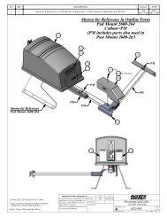
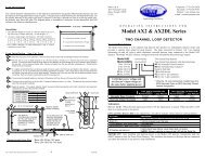
D811007_04Nel ringraziarVi per la preferenza accordata a questo prodotto, la ditta ècerta che da esso otterrete le prestazioni necessarie al Vostro uso.Leggete attentamente l’opuscolo “AVVERTENZE” ed il “LIBRETTO ISTRU-ZIONI” che accompagnano questo prodotto in quanto forniscono importantiindicazioni riguardanti la sicurezza, l’installazione, l’uso e la manutenzione.Questo prodotto rispon<strong>de</strong> alle norme riconosciute <strong>de</strong>lla tecnica e <strong>de</strong>lladisposizioni relative alla sicurezza . Confermiamo che è conforme alleseguenti direttive europee: 89/336/CEE, 73/23/CEE e loro modifichesuccessive.1) GENERALITÀL’automazione E5, è costituita da un compatto motoriduttoreelettromeccanico di minimo ingombro, che grazie alla sua versatilità puòessere applicato su qualsiasi pilastro o colonnina. Il bloccaggio <strong>de</strong>l cancelloin chiusura è garantito da una elettroserratura, e la manovra manualed’emergenza si esegue facilmente, dopo avere sbloccato l’elettroserraturacon la chiave personalizzata in dotazione, grazie alla reversibilità <strong>de</strong>lmotoriduttore.La totale sicurezza contro lo schiacciamento è garantita da una frizione adischi multipli, ed il funzionamento a fine corsa è regolato con temporizzatore.Il motoriduttore (fig.1) è costituito da : Monoblocco motore “M”, Riduttoreepicicloidale “R”, Frizione meccanica a dischi multipli “F”, Braccio di spinta “B”.2) DATI TECNICIAlimentazione monofase 230 V~ ±10% 50 Hz (*)Motore 1400 min -1Potenza massima 200 WRapporto di riduzione 1/1296Con<strong>de</strong>nsatore 8 µFAssorbimento0.8 ALubrificazioneGrasso permanenteMassima coppia300NmVelocità di apertura 22 s (~ 6,5°/s)Peso massimo anta 2000N (~200 kg)Massima lunghezza anta 1800 mmMassimo grado apertura 130° - 180° con braccio a slittaReazione all’urtoFrizione meccanica multidischiManovra manuale Sblocco elettroserratura con chiaveN° manovre in 24 h 50Condizioni ambientali -10 °C +60 °CGrado di protezione IP 44Peso operatore8 kgDimensioniVe<strong>de</strong>re fig.2(*) Tensioni speciali a richiesta3) INSTALLAZIONE DELL’AUTOMAZIONE3.1) Verifiche preliminariControllare che:- Che la struttura <strong>de</strong>l cancello sia sufficientemente robusta. La posizione difissaggio <strong>de</strong>ve essere valutata secondo la struttura <strong>de</strong>ll’anta. In ogni caso,il braccio di manovra <strong>de</strong>ve spingere in un punto <strong>de</strong>ll’anta rinforzato.- Che le ante si muovano manualmente e senza sforzo per tutta la corsa.Se il cancello non è di nuova installazione, controllare lo stato di usura ditutti i componenti.Sistemare o sostituire le parti difettose o usurate.L’affidabilità e la sicurezza <strong>de</strong>ll’automazione è direttamente influenzatadallo stato <strong>de</strong>lla struttura <strong>de</strong>l cancello.3.2) Applicazioni previsteLa posizione standard di montaggio <strong>de</strong>l Mod. E5 è rappresentata in fig.3.Tuttavia se si vuole automatizzare un cancello pedonale con anta fino a 1,4metri di lunghezza, si può aumentare la velocità di apertura avvicinando laposizione di attacco cancello “A” al cardine (fig.4) o accorciando la levasnodata “L2” (fig.5).Se la quota minima di 210mm <strong>de</strong>l disegno di fig.6 non può essere rispettataa causa <strong>de</strong>lla presenza di un muro in angolo, si può utilizzare il braccio aslitta (fig.7) ; in questo caso però l’anta <strong>de</strong>ve avere una lunghezza massimafino a 1,6 metri ed un peso massimo di 100kg.Se la misura massima di 200mm (fig.3) non può essere rispettata a causa<strong>de</strong>l pilastro troppo grosso, si può usare la versione E5L con entrambi ibracci “L1-L2” allungati (fig.8). Per Cancelli pesanti con ante fino a 2 metrie 200 kg di peso, si può richie<strong>de</strong>re il braccio “L2” allungato (fig.9) chesviluppa una maggiore forza; in questo caso, tenere presente che il tempodi apertura aumenta perché aumentano i gradi di rotazione <strong>de</strong>lla leva “L1”.Se si vuole automatizzare un cancello con apertura angolare di 180°(fig.10) o se nel pilastro non c’è spazio per applicare il motore, è possibileeseguire uno scanso nell’anta in corrispon<strong>de</strong>nza al cardine <strong>de</strong>l cancello(fig.11); in questo caso il peso <strong>de</strong>ll’anta non <strong>de</strong>ve essere sostenuto dalMANUALE PER L’INSTALLAZIONEITALIANOmotoriduttore e la singola anta <strong>de</strong>ve avere una lunghezza massima di 1,6metri ed un peso massimo di 100kg.ATTENZIONE ! L’attuatore mod. E5 non <strong>de</strong>ve essere installato conil gruppo frizione rivolto verso il basso.4) ANCORAGGIO DEL MOTORIDUTTORELa piastra di sostegno <strong>de</strong>l motoriduttore, viene fissata al pilastro neiseguenti modi:- Se il pilastro è di metallo, con una robusta saldatura elettrica (fig.12).- Se il pilastro è in muratura, la piastra dovrà essere ancorata in profonditàmediante idonee zanche “Z” saldate sul retro <strong>de</strong>lla stessa (fig.13).- Se il pilastro è di pietra, ed il cancello è piccolo e non richie<strong>de</strong> moltaforza per l’apertura, si può fissare la piastra con quattro tasselli metalliciad espansione “T” (fig.14).- Se il pilastro è di pietra ed il cancello è gran<strong>de</strong>, saldare la piastra su unacontropiastra angolare “C”, fissata con quattro tasselli ad espansione (fig.15).- Terminato il fissaggio <strong>de</strong>lla piastra di ancoraggio si monta il motoriduttore (fig.16).- A cancello chiuso, allentare la frizione (fig.23) e posizionare il bracciomotore in modo che formi un angolo di pressione come indicato nellevarie figure di posizionamento.- Bloccare provvisoriamente (con pinze a scatto) l’attacco “A” (fig.17) all’antaed eseguire l’apertura manuale <strong>de</strong>ll’anta. Controllare che il bracciomotore non crei condizioni di pericolo di schiacciamento oimbrigliamento durante tutto il movimento.- Fissaggio la forcella di attacco “A” all’anta (fig.17) praticando quattro forifilettati “F” nel punto prescelto.- Fare attenzione che il braccio risulti ben livellato (fig.18).- Nei motoriduttori con braccio a slitta Mod. E5S, la slitta “S” viene fissatacon la feritoia di scorrimento rivolta verso il suolo (fig.19); essa <strong>de</strong>verisultare alla massima distanza dal pilastro permessa dal braccio “L1”.5) APPLICAZIONE DELL’ELETTROSERRATURALa reversibilità <strong>de</strong>l motoriduttore ren<strong>de</strong> necessaria l’applicazione di unaelettroserratura.Il tipo di elettroserratura fornito dalla ditta è il Mod. EBP (fig.20). Costituitada un elettromagnete a servizio continuo con aggancio al suolo. In questodispositivo l’eccitazione rimane per tutto il tempo di lavoro <strong>de</strong>l motoriduttore,consentendo al <strong>de</strong>nte di aggancio “D” di arrivare in battuta di chiusurasollevato, evitando strisciamenti al suolo che potrebbero compromettere ilmovimento.Nel caso di cancello a due ante, l’anta con elettroserratura <strong>de</strong>ve chiu<strong>de</strong>rsiper ultima. Utilizzare una centralina di comando con la regolazione diritardo in chiusura <strong>de</strong>lla seconda anta.6) BATTUTE DI ARRESTOÈ obbligatorio posizionare le battute di arresto “F” (fig.21), sia in aperturache in chiusura, per fermare la corsa <strong>de</strong>lle ante nella posizione <strong>de</strong>si<strong>de</strong>rata.7) PREDISPOSIZIONE IMPIANTO ELETTRICOPredisporre l’impianto elettrico come indicato in fig.22 facendo riferimentoalle norme vigenti per gli impianti elettrici CEI 64-8, IEC364, armonizzazioneHD384 ed altre norme nazionali. Tenere nettamente separati i collegamentidi alimentazione di rete dai collegamenti di servizio (fotocellule, dispositividi comando ecc.).In fig.22 è riportato il numero di collegamenti e la sezione per una lunghezzadi 100 metri; per lunghezze superiori, calcolare la sezione per il carico reale<strong>de</strong>ll’automazione.I componenti principali per una automazione sono (fig.22):I Interruttore onnipolare omologato con apertura contati di almeno3mm provvisto di protezione contro i sovraccarichi ed i corto circuiti,atto a sezionare l’automazione dalla rete. Se non presente, preve<strong>de</strong>rea monte <strong>de</strong>ll’automazione un interruttore differenziale omologatodi a<strong>de</strong>guata portata con soglia da 0,03A.QR Quadro comando e ricevente incorporataSPL Scheda di preriscaldamento a bordo <strong>de</strong>l quadro per funzionamentoa temperature inferiori ai -10°C (opzionale)S Selettore a chiaveAL Lampeggiante con antenna accordataM OperatoriE ElettroserraturaFte,Fre Coppia fotocellule esterneFti,Fri Coppia fotocellule interne con colonnineT Trasmittente 1-2-4 canaliATTENZIONE! Per il collegamento <strong>de</strong>gli accessori riferirsi ai relativimanuali istruzione. I quadri di comando e gli accessori <strong>de</strong>vono essereadatti all’utilizzo e conformi alle normative di sicurezza vigenti.E5 -Ver. 04- 3
ITALIANO8) REGOLAZIONE COPPIA MOTORE (FRIZIONE)La regolazione di coppia <strong>de</strong>l motore si effettua nel motoriduttore medianteuna frizione meccanica a dischi multipli (fig.23).La regolazione <strong>de</strong>lla frizione, eseguita da personale qualificato (installatore),<strong>de</strong>ve essere tarata per la minima forza necessaria ad effettuare la corsadi apertura e chiusura completa. Comunque non <strong>de</strong>ve superare i valori dispinta in punta all’anta, previsti dalle norme nazionali vigenti. Per l’Italia,questo valore non <strong>de</strong>ve superare i 150N.ATTENZIONE ! Non bloccare completamente la vite che regola questodispositivo ; questo comprometterebbe la sicurezza <strong>de</strong>ll’automazionee potrebbe anche danneggiare l’attuatore.La regolazione si effettua come segue.Togliere il coperchio “A” e con l’apposita chiave “B” ruotare per brevi trattila vite “C”, tenendo presente che : girando in senso orario (verso +), lafrizione si carica, girando in senso antiorario (verso -), la frizione si allenta.Eseguire la regolazione in ogni attuatore installato e riposizionare ilcoperchio “A”.In fig.24, è riportata la sequenza di montaggio <strong>de</strong>i componenti <strong>de</strong>lla frizionedi seguito elencati per nome : A) coperchio, C) vite di regolazione, E) mollaa tazza, F) dischi frizione a calettatura interna, G) dischi frizione a calettaturaesterna, H) Braccio, I) ron<strong>de</strong>lla spessore, L) Albero riduttore scanalato.9) FINECORSAGli attuatori, non dispongono di finecorsa elettrici. Pertanto <strong>de</strong>vono esserecomandati da una centralina dotata di regolazione <strong>de</strong>l tempo di lavoro.Quando l’anta arriva in battuta d’arresto la frizione slitta ed il motore rimanealimentato fino al termine <strong>de</strong>l tempo di lavoro impostato. Il tempo di lavoro,impostabile nella centralina di comando per mezzo di un trimmer, è correttoquando il tempo impostato è di circa 3-5 secondi superiore al tempoeffettivamente impiegato dal cancello per effettuare completamente ilmovimento di apertura-chiusura. Nel caso di anta in ritardo, regolare iltempo di lavoro in chiusura. Minore è il tempo in cui il moto funziona inbattuta d’arresto, minore sarà l’usura <strong>de</strong>lla frizione.Nel caso si utilizzino finecorsa esterni di tipo elettrico riportiamo in fig.25-26 due diversi modi di installazione. I finecorsa <strong>de</strong>vono essere di tipostagno. Per il loro collegamento, consultare le istruzioni <strong>de</strong>lla centralina dicomando.10) MANOVRA DI EMERGENZAEssendo il motoriduttore reversibile, in caso di mancanza di alimentazione,è sufficiente sbloccare l’elettroserratura e spingere manualmente le ante.Quando ritorna l’alimentazione di rete, l’automazione funziona automaticamente.11) VERIFICA DELL’AUTOMAZIONEPrima di ren<strong>de</strong>re <strong>de</strong>finitivamente operativa l’automazione, controllarescrupolosamente quanto segue:- Controllare il corretto funzionamento di tutti i dispositivi di sicurezza (frizione,fotocellule, coste sensibili ecc.)- Verificare che la spinta (antischiacciamento) <strong>de</strong>ll’anta sia entro i limitiprevisti dalle norme vigenti.- Verificare il comando di apertura manuale.- Verificare l’operazione di apertura e chiusura con i dispositivi di comandoapplicati.- Verificare la logica elettronica di funzionamento normale e personalizzata.12) USO DELL’AUTOMAZIONEPoiché l’automazione può essere comandata a distanza medianteradiocomando o pulsante di start, e quindi non a vista, è indispensabilecontrollare frequentemente la perfetta efficienza di tutti i dispositivi disicurezza. Per qualsiasi anomalia di funzionamento, intervenire rapidamenteavvalendosi anche di personale qualificato.Si raccomanda di tenere i bambini a <strong>de</strong>bita distanza dal raggio d’azione<strong>de</strong>ll’automazione.13) COMANDOL’utilizzo <strong>de</strong>ll’automazione consente l’apertura e la chiusura <strong>de</strong>lla porta inmodo motorizzato. Il comando può essere di diverso tipo (manuale, conradiocomando, controllo accessi con badge magnetico ecc.) secondo lenecessità e le caratteristiche <strong>de</strong>ll’installazione. Per i vari sistemi di comando,ve<strong>de</strong>re le relative istruzioni.Gli utilizzatori <strong>de</strong>ll’automazione <strong>de</strong>vono essere istruiti al comando e all’uso.MANUALE PER L’INSTALLAZIONE- Far controllare da personale qualificato (installatore) la corretta regolazione<strong>de</strong>lla frizione elettrica.- Per qualsiasi anomalia di funzionamento, non risolta, togliere alimentazioneal sistema e richie<strong>de</strong>re l’intervento di personale qualificato (installatore).15) RUMOROSIÁIl rumore aereo prodotto dal motoriduttore in condizioni normali di utilizzoè costante e non supera i 70dB(A).16) DEMOLIZIONEL’eliminazione <strong>de</strong>i materiali va fatta rispettando le norme vigenti.Nel caso di <strong>de</strong>molizione <strong>de</strong>ll’automazione non esistono particolari pericolio rischi <strong>de</strong>rivanti dall’automazione stessa.È opportuno in caso di recupero <strong>de</strong>i materiali, che vengano separati pertipologia (parti elettriche - rame - alluminio - plastica - ecc.).17) SMANTELLAMENTONel caso l’automazione venga smontata per essere poi rimontata in altrosito, bisogna:- Togliere l’alimentazione e scollegare tutto l’impianto elettrico.- Togliere il motoriduttore dalla base di fissaggio.- Smontare il quadro di comando se separato e tutti i componenti <strong>de</strong>ll’installazione.- Nel caso alcuni componenti non possano essere rimossi o risultino danneggiati,provve<strong>de</strong>re alla loro sostituzione.18) MALFUNZIONAMENTO. CAUSE e RIMEDI.18.1) Il cancello non apre. Il motore funziona, ma non avviene il movimentodi apertura.1) Verificare se l’elettroserratura scatta correttamente.2) Controllare che non vi siano difetti di assetto meccanico <strong>de</strong>l cancello, esempiointerferenze con le battute d’arresto o fra i battenti <strong>de</strong>lle ante stesse.3) Controllare se la frizione slitta. Eventualmente caricarla ruotando la viteverso il segno + (max spinta consentita 150N).4) Se il motore ruota in verso opposto a quello che dovrebbe girare(si controlla la rotazione alzando il coperchio <strong>de</strong>lla frizione), invertire icollegamenti di marcia <strong>de</strong>l motore stesso.Nel caso le condizioni sopraelencate diano esito negativo, sostituirel’attuatore.18.2) Il cancello non apre o non chiu<strong>de</strong>. Il motore non funziona, e nonsi avverte alcun rumore.1) Verificare che la centralina sia alimentata correttamente.2) Verificare che fotocellule o coste sensibili non siano impegnate.3) Verificare che l’apparecchiatura elettronica sia regolarmente alimentata.Verificare l’integrità <strong>de</strong>i fusibili.4) Verificare che le funzioni <strong>de</strong>ll’apparecchiatura elettronica siano correttemediante i leds di diagnostica o tramite controllo visivo.5) Controllare che non vi siano radiocomandi, pulsanti di start o altridispositivi di comando che mantengono chiuso (N.C.) il contatto di start.Nel caso le condizioni sopraelencate diano esito negativo, sostituire lacentralina di comando.18.3) Il motore è rumoroso quando l’anta è in battuta nei fermi d’arresto.1) Quando la frizione slitta perché l’anta ha raggiunto le battute d’arresto,l’anta <strong>de</strong>ve essere ferma e non permettere oscillazioni a scatti <strong>de</strong>lla stessa.Se ci sono movimenti a scatto, rinforzare l’anta in modo da eliminareil problema.2) Se non è possibile rinforzare l’anta, ridurre il tempo di lavoro affinché lafrizione slitti il meno possibile.3) Se i dischi sono lucidi, carteggiarli o, se persiste il problema, sostituirli.Le <strong>de</strong>scrizioni e le illustrazioni <strong>de</strong>l presente manuale non sonoimpegnative. Lasciando inalterate le caratteristiche essenziali <strong>de</strong>lprodotto, la Ditta si riserva di apportare in qualunque momento lemodifiche che essa ritiene convenienti per migliorare tecnicamente -costruttivamente e commercialmente il prodotto, senza impegnarsiad aggiornare la presente pubblicazione.D811007_0414) MANUTENZIONEPer qualsiasi manutenzione, togliere alimentazione al sistema.- Ingrassare periodicamente i punti di snodo <strong>de</strong>l braccio di manovra.- Eseguire saltuariamente la pulizia <strong>de</strong>lle ottiche <strong>de</strong>lle fotocellule.4 - E5 -Ver. 04
D811007_04Thank you for buying this product. Our company is sure that you will bemore than satisfied with the product’s performance.Carefully read the “WARNINGS” pamphlet and the “INSTRUCTIONBOOKLET” which are supplied together with this product, since theyprovi<strong>de</strong> important information regarding the safety, installation, use andmaintenance of the product.This product complies with recognised technical standards and safetyregulations. We <strong>de</strong>clare that this product is in conformity with the followingEuropean Directives: 89/336/EEC, 73/23/EEC and following amendments.1) GENERAL OUTLINEThe E5 mo<strong>de</strong>l consists of a compact electromechanical gearmotor withminimum overall dimensions which can be installed on any post or pillarthanks to its versatility. Gate locking in the closing position is guaranteedby an electric lock. The reversibility of the gearmotor allows immediatemanual manoeuvring of the gate in case of emergency, by means of theappropriate personalised key releasing the electric lock. Total anti-squashsafety is provi<strong>de</strong>d by a multiple-disk clutch and the end-of-stroke operationis set by a timer.The gearmotor (fig.1) is ma<strong>de</strong> up of : Motor single-block “M”, Epicycloidalreducing gear “R”, Multiple-disk mechanical clutch “F”, Pushing arm “B”.2) TECHNICAL SPECIFICATIONSPower supply 230V~ ±10% 50Hz single-phase (*)Motor 1400 min -1Max. power200WReduction ratio 1/1296Capacitor 8µFAbsorbed current 0,8ALubricationPermanent greaseMax. torque300 NmOpening speed22 s (~ 6,5 °/s)Max. leaf weight2000N (~200kg)Max. leaf length1.800mmMax opening <strong>de</strong>grees 130° 180° with sli<strong>de</strong> armImpact reactionMultiple-disk mechanical clutch<strong>Manual</strong> manoeuvreElectric lock release with keyNo. manoeuvres in 24 h 50Environmental conditions -10°C to +60°CDegree of protection IP 44Controller weight8 kgDimensionsSee fig.2(*) Special voltages on request3) INSTALLATION OF THE ACTUATOR3.1) Preliminary checksCheck:- That the structure of the gate is strong enough. The fixing position mustbe <strong>de</strong>termined according to the leaf structure. In any case, the drive armmust push against a reinforced point in the leaf;- That the leaves can be moved manually without excessive effort for thewhole of their stroke;- If the gate being installed is not new, check whether its components areworn.Repair or replace any worn or damaged parts.Automation reliability and safety are directly influenced by the condition ofthe gate structure.3.2) Standard installationFig. 3 shows the standard installation position for Mod. E5. However, if theautomation must be fitted onto a gate with a pe<strong>de</strong>strian access and with aleaf with up to 1.4 m length, the opening speed can be increased by bringingthe gate fastening position “A” near to the hinge-pivot (fig.4) or by shorteningthe articulated lever “L2” (fig.5).If the minimum value equal to 210mm indicated in the drawing of fig.6 is notavailable due to the presence of a wall in the corner, use a sli<strong>de</strong> arm (fig.7);in this case, make sure that the length of the leaf does not exceed 1.6metres and its weight is 100 kg max.If the maximum value equal to 200mm (fig.3) is not available due to a toolarge gate-post, use version E5L with both arms “L1-L2” exten<strong>de</strong>d (fig.8).For heavy gates with leaves with up to 2 m length 200 kg weight, requestan exten<strong>de</strong>d “L2” arm (fig.9) featuring increased power; in this case, theopening time will be longer because the rotation <strong>de</strong>grees of lever “L1” areincreased. If the automation must be fitted onto a gate with 180° angularopening (fig.10) or there is no space in the gate-post to mount the motor,a recess should be ma<strong>de</strong> in the leaf in correspon<strong>de</strong>nce with the gate hingepivot(fig.11); in this case the weight of the leaf must not be supported bythe gearmotor and the length of the single leaf must not exceed 1.6 m andINSTALLATION MANUALENGLISHits weight not be greater than 100 kg.WARNING! The controller mod. E5 must not be installed with theclutch unit facing downward.4) FITTING OF THE GEARMOTORTo fit the gearmotor supporting plate onto the gate-post proceed as follows:- With a good electric welding (fig. 12) if the gate-post in ma<strong>de</strong> of metal.- If the gate-post is in brick, the plate must be set soundly into the postusing a<strong>de</strong>quately sized cramps “Z” wel<strong>de</strong>d to the back of the plate (fig.13).- If the gate-post is in stone and the gate is small and therefore does notrequire excessive power to be opened, the plate can be mounted withfour metal expansion plugs “T” (fig. 14).- If the gate-post is in stone and a large gate is being installed it would bebetter to weld the plate to a corner plate “C” fixed with four expansionplugs (fig. 15).- After fastening the anchoring plate, fit the gearmotor (fig. 16).- Close the gate and loosen the clutch (fig. 23). Position the drive arm soas to create a pressing angle as shown in the figures for positioning.- Temporarily lock the fastening element “A” (fig. 17) to the leaf (usinglocking pliers) and open the leaf manually.Check that the drive arm does not cause any crushing or entanglementrisks when moving.- Secure the fastening fork “A” to the leaf (fig. 17) using the four threa<strong>de</strong>dholes “F” to be ma<strong>de</strong> in the selected position.- Check that the arm is level (fig. 18).- In the case of gearmotors equipped with the sli<strong>de</strong> arm Mod. E5S, thesli<strong>de</strong> “S” should be secured with its sliding slit facing the ground (fig, 19);the sli<strong>de</strong> must be located at the maximum distance from the gate-postallowed by the arm “L1”.5) FITTING THE ELECTRIC LOCKDue to the reversibility of the gearmotor, an electric lock must be fitted.The company supplies a special electric lock Mod. EBP (fig. 20) whichconsists of a continuous electromagnet with ground catch. This <strong>de</strong>viceremains energised during the total operation time of the gearmotor so as thebolt “D” can reach the closing limit stop lifted without creating any frictionwith the ground and guaranteeing a smooth movement.If the gates has two leaves, the leaf equipped with the electric lock shouldclose last.Use a control unit with closing <strong>de</strong>lay adjustment for the second leaf.6) GATE STOP LIMITSIt is compulsory to fit the gate stop limits “F” (fig.21), both in opening andclosing positions, to stop the strokes of the leaves in the <strong>de</strong>sired positions.7) ELECTRICAL PLANT SET-UPSet the electrical plant as shown in fig. 22 according to the currentstandards for electrical plants CEI 64-8, IEC364, Harmonization HD384and other national regulations. Keep the power supply connections <strong>de</strong>finitelyseparated from the auxiliary connections (photocells, control <strong>de</strong>vices, etc.).Fig. 22 indicates the number of connections and the sections for 100 m.long power supply cables. For distances of over 100 m., calculate the cablesection <strong>de</strong>pending on the automation actual load.The automation main components are the following (fig. 22):I Type approved omnipolar switch with 3 mm min. contact openingprovi<strong>de</strong>d with overload and short-circuit protection, used to breakthe automation connection from the mains. If not present, provi<strong>de</strong>the automation with a type approved differential switch with a<strong>de</strong>quatecapacity and a 0.03 A threshold.QR Control unit with built-in receiverSPL Pre-heating board on the control panel for operation at temperaturesbelow -10° C (optional)S Key selectorAL Blinker tuned in with antennaM ActuatorsE Electric lockFte,FrePair of outsi<strong>de</strong> photocellsFti, Fri Pair of insi<strong>de</strong> photocells with columnsT 1-2-4 channel transmitterWARNING! For the connection of the accessories, please refer to therelevant instruction manuals. The type of control boards andaccessories must be suitable for the inten<strong>de</strong>d use and in compliancewith the current safety standards.8) MOTOR TORQUE ADJUSTMENT (CLUTCH)The motor torque adjustment is carried out in the gearmotor by means ofE5 -Ver. 04- 5
ENGLISHthe mechanical multiple-disk clutch (fig.23).The adjustment of the clutch must be carried out by qualified personnel(installer) and inclu<strong>de</strong>s the calibration of the clutch to the minimum forcenee<strong>de</strong>d to complete full opening and closing strokes. The calibration mustnever exceed the values of the pushing force measured on the leaf edgeaccording to the national standards in force. In Italy the admitted value isequal to 150N.WARNING! Do not secure completely the adjustment screw of this<strong>de</strong>vice; this could compromise the safety of the automation and thecontroller could get damaged.Carry out the adjustment as follows:Remove the cover “A” and rotate from time to time small sections of thescrew “C” using the appropriate spanner “B”. To tighten the clutch, rotatethe screw clockwise (towards +), to loosen the clutch, rotate the screwanticlockwise (towards -).Carry out the adjustment on every controller mounted and refit the cover “A”.Fig.24 indicates the assembly sequence for the clutch components: A)cover, C) adjustment screw, E) Belleville washer, F) clutch disks with insi<strong>de</strong>keying, G) clutch disks with outsi<strong>de</strong> keying, H) arm, I) shim washer, L)grooved reduction shaft.9) LIMIT SWITCHESThe controllers are not equipped with electric limit switches. For thisreason, they must be controlled by a control unit with adjustment of theoperation time. When the leaf reaches the gate stop limit the clutch sli<strong>de</strong>sand the motor remains energised until the total operation time set haselapsed. The operation time can be set on the control unit by means of atrimmer. The time is correct when the time set is 3-5 seconds greater thanthe actual time nee<strong>de</strong>d to complete one full opening and closing cycle. If theleaf is too slow, adjust the operation time in closing position. The less themovement time at the end of stroke is, the longer the clutch life will be.If external electric limit switches are used, refer to the two differentinstallation methods in fig.25-26. The limit switches must be sealed. Toconnect the limit switches, refer to the instructions for the control unit.10)EMERGENCY MANOEUVRESince the gearmotor is reversible, release the electric lock and move theleaves manually in the case of a power failure. When the power supply hasbeen restored, the automation operates automatically.11) CHECKING THE AUTOMATIONBefore consi<strong>de</strong>ring the automation completely operational, the followingchecks must be ma<strong>de</strong> with great care:Check that all the safety means work properly (i.e. clutch, photocells,pneumatic skirts, etc.).Check that the thrust (anti-squash) of the leaf is within the limits prescribedby the standards in force.Check the manual opening control.Check the opening and closing manoeuvres using the controls.Check the control unit’s electronic logic in normal or customised operation.12) USE OF THE AUTOMATIONSince the automation may be remote controlled either by radio or a startbutton (and therefore not visually), it is essential that all safeties arechecked frequently.Any malfunction should be corrected immediately by qualified personnel.Keep children at a safe distance from the field of action of the automation.13) THE CONTROLSWith the automation the gate has a power driven opening and closing. Thecontrols can come in various forms (i.e. manual, remote controlled, limitedaccess by magnetic badge, etc.) <strong>de</strong>pending on needs and installationcharacteristics. For <strong>de</strong>tails on the various command systems, consult thespecific instruction booklets.Anyone using the automation must be instructed on its operation andcontrols.INSTALLATION MANUAL15) NOISEThe aerial noise produced by the gearmotor un<strong>de</strong>r normal operatingconditions is constant and does not exceed 70dB(A).16) SCRAPPINGMaterials must be disposed of in conformity with the current regulations.In case of scrapping, the automation <strong>de</strong>vices do not entail any particularrisks or danger. In case of recovered materials, these should be sorted outby type (electrical components, copper, aluminium, plastic etc.).17) DISMANTELLINGWhen the automation system is disassembled to be reassembled onanother site, proceed as follows:• Disconnect the power supply and the entire electrical installation.• Remove the gearmotor from its fixing base.• Disassemble the control panel, if separate, and all installationcomponents.• In the case where some of the components cannot be removed or aredamaged, they must be replaced.18) TROUBLESHOOTING18.1) The gate does not open. The motor runs, but the openingmovement does not start.1) Check if the electric lock works correctly.2) Check if the mechanical arrangement of the gate is faulty, e.g. there areinterferences with the gate stop limits or between the edges of the leaves.3) Check if the clutch sli<strong>de</strong>s and, if necessary, tighten it by rotating the screwtowards the + sign (max. thrust allowed 150N).4) If the motor runs in the direction opposite to the right one, invert the drivingconnections of the motor (check rotation by lifting the clutch cover).If after having carried out the checks listed above the problem persists,replace the controller.18.2) The gate does not open or close. The motor does not run and nosound is heard.1) Check that the control unit is correctly powered.2) Check that the photocells or the rubber skirts are not engaged.2) Check that the electronic equipment is correctly powered. Check that thefuses are not damaged.4) Check that the electronic functions of the equipment are correct by meansof the diagnostic LEDs or through a visual inspection.5) Check that no remote controls, start buttons or other <strong>de</strong>vices are keepingthe start contact (N.C.) closed.If after having carried out the checks listed above the problem persists,replace the control unit.18.3) The noise originating from the motor is high when the leafencounters the gate stop limit.1) When the clutch sli<strong>de</strong>s because the leaf has reached the gate stop limit,the leaf must be still and no oscillations should be noticed. If jog movementsare noticed, reinforce the leaf so as to eliminate the problem.2) If the leaf cannot be reinforced, <strong>de</strong>crease the working time so that theclutch sli<strong>de</strong>s as little as possible.3) If the disks are bright, restore them with sandpaper or, if necessary, replacethem.The <strong>de</strong>scriptions and illustrations contained in the present manualare not binding. The Company reserves the right to make any alterations<strong>de</strong>emed appropriate for the technical, manufacturing and commercialimprovement of the product, while leaving the essential productfeatures unchanged, at any time and without un<strong>de</strong>rtaking to updatethe present publication.D811007_0414) MAINTENANCEAll maintenance operations must be performed with the system powersupply shut off.Lubricate periodically the articulated elements of the drive arm.Clean the optical system of the photocells every now and then.Have the adjustment of the electric clutch checked by a qualified specialist(installer).For any malfunction that remains unsolved, shut off the power to the systemand call a qualified specialist (installer).6 - E5 -Ver. 04
D811007_04Nous vous remercions pour avoir choisi ce produit. Nous sommes certainsqu’il vous offrira les performances que vous souhaitez.Lisez attentivement la brochure “AVERTISSEMENTS” et le “MANUELD’INSTRUCTIONS” qui accompagnent ce produit, puisqu’ils fournissentd’importantes indications concernant la sécurité, l’installation, l’utilisationet l’entretien.Ce produit est conforme aux règles reconnues <strong>de</strong> la technique et auxdispositions <strong>de</strong> sécurité. Nous certifions sa conformité avec les directiveseuropéennes suivantes: 89/336/CEE, 73/23/CEE et leurs amen<strong>de</strong>dsuccessives.1) GENERALITESLa motorisation E5 est constituée d’un motoréducteur électromécaniquecompact aux dimensions très faibles qui, grâce à sa facilité d’installation,peut être appliqué sur n’importe quel linteau ou colonnette. Le blocage duportail en fermeture est assuré par une serrure électrique et la manoeuvremanuelle d’urgence se fait facilement après avoir déverrouillé la serrureélectrique avec la clé personnalisée fournie en dotation, grâce à laréversibilité du motoréducteur.La sécurité totale antiécrasement est assurée par un embrayage à disquesmultiples et le fonctionnement à la fin <strong>de</strong> course est réglé par temporisateur.Le motoréducteur (fig. 1) est constitué par: Monobloc moteur «M», Réducteurépicycloï<strong>de</strong> «R», Embrayage mécanique à disques multiples «F», Bras <strong>de</strong>poussée «B».2) CARACTERISTIQUES TECHNIQUESAlimentation monophasée 230 V ±10% 50 Hz (*)Moteur 1400 min -1Puissance maxi200 WRapport <strong>de</strong> réduction 1/1296Con<strong>de</strong>nsateur 8 µFCourant absorbé0,8 ALubrificationGraisse permanenteCouple maxi300 NmVitesse d’ouverture22 s (6,5 °/s)Poids maxi du battant 2000N (~200 kg)Longueur maxi du battant 1800 mmDegré maxi <strong>de</strong> débattement 130° - 180° avec bras à coulisseRéaction au chocEmbrayage mécanique multidisquesManoeuvre manuelle Déverrouillage serrure électrique avec cléN° <strong>de</strong> manoeuvres en 24 h 50Conditions ambiantes -10°C à +60°CDegré <strong>de</strong> protection IP 44Poids <strong>de</strong> l’actionneur 8 kgDimensions Voir fig. 2(*) Tensions spéciales sur <strong>de</strong>man<strong>de</strong>MANUEL D’INSTALLATIONFRANÇAISsuffisante pour appliquer le moteur, il est possible d’effectuer une nichedans le vantail au niveau du gond du portail ( fig. 11); dans ce cas, le poidsdu vantail ne doit pas être supporté par le motoréducteur et chaque vantaildoit avoir une longueur maxi <strong>de</strong> 1,6 mètres et un poids maxi <strong>de</strong> 100 Kg.ATTENTION: Le vérin mod. E5 ne doit pas être installé avec le groupeembrayage dirigé vers le bas.4) ANCRAGE DU MOTOREDUCTEURLa plaque <strong>de</strong> soutien du motoréducteur est fixée au linteau comme suit:• Si le linteau est en métal, par une robuste soudure électrique (fig. 12).• Si le linteau est en maçonnerie, la plaque <strong>de</strong>vra être ancrée en profon<strong>de</strong>urpar <strong>de</strong>s agrafes robustes “Z” soudées à l’arrière <strong>de</strong> la plaque (fig. 13).• Si le linteau est en pierre et le portail est petit et n’exige donc pasbeaucoup <strong>de</strong> force pour l’ouverture, la plaque peut être fixée par quatrechevilles «T» (fig. 14).• Si le linteau est en pierre et le portail est grand, il faut sou<strong>de</strong>r la plaquesur une contre-plaque angulaire “C”, fixée par quatre chevilles «T» (fig.15).• Une fois la fixation <strong>de</strong> la plaque d’ancrage terminée, il faut monter lemotoréducteur (fig. 16).• Avec le portail fermé, relâcher l’embrayage (fig. 23) et positionner lebras moteur <strong>de</strong> telle façon qu’il forme un angle <strong>de</strong> pression commeindiqué dans les figures <strong>de</strong> positionnement.• Bloque provisoirement (par <strong>de</strong>s pinces) la fixation “A» (fig. 17) au vantailet effectuer l’ouverture manuelle du vantail. S’assurer que le bras moteurn’engendre pas <strong>de</strong>s situations dangereuses d’écrasement oud’emprisonnement pendant tout le mouvement.• Fixer la fourche <strong>de</strong> fixation «A» au vantail (fig. 17) en exécutant quatretrous filetés «F» à l’endroit choisi.• Faire attention à ce que le bras résulte bien nivelé (fig. 18).• Dans les motoréducteurs avec bras à coulisse Mod. E5S, la glissière«S» est fixée avec la fente <strong>de</strong> coulissement vers le sol (fig. 19); elle doitêtre située à la distance maximale du linteau permise par le bras «L1».5) APPLICATION DE LA SERRURE ELECTRIQUELa réversibilité du motoréducteur rend nécessaire l’application d’uneserrure électrique.Le type <strong>de</strong> serrure électrique fourni par le constructeur est le Mod. EBP (fig.20), constituée par un électro-aimant à service continu avec accrochage ausol. Ce dispositif reste excité pendant tout le temps <strong>de</strong> travail dumotoréducteur et ceci permet à la <strong>de</strong>nt d’accrochage «D» d’arriver à labutée soulevée, en évitant <strong>de</strong>s frottements au sol qui pourraientcompromettre le mouvement.En cas <strong>de</strong> portail à <strong>de</strong>ux vantaux, le vantail avec serrure électrique doit sefermer le <strong>de</strong>rnier. Utiliser une centrale <strong>de</strong> comman<strong>de</strong> avec possibilité <strong>de</strong>régler le retard en fermeture du <strong>de</strong>uxième vantail.3) INSTALLATION DE LA MOTORISATION3.1) Vérifications préliminairesContrôler:que la structure du portail soit suffisamment robuste. La position <strong>de</strong> fixationdoit être évaluée selon la structure du vantail. En tous les cas, le bras <strong>de</strong>manoeuvre doit pousser le vantail à un endroit renforcé.que les vantaux bougent manuellement sans effort pour toute la course.Si le portail n’a pas été installé récemment, contrôler l’état d’usure <strong>de</strong> tousles organes.Réparer ou remplacer les parties défectueuses ou usées.La fiabilité et la sécurité <strong>de</strong> la motorisation sont directement influencées parl’état <strong>de</strong> la structure du portail.3.2) Applications prévuesLa position standard <strong>de</strong> montage du Mod. E5 est représentée dans la fig.3. Si toutefois l’on veut motoriser un portail piétonnier avec vantail jusqu’à1,4 m <strong>de</strong> longueur, on peut augmenter la vitesse d’ouverture en approchantla position <strong>de</strong> fixation du portail «A» au gond (fig. 4) ou en réduisant lalongueur du levier articulé «L2» (fig. 5).Si la cote mini <strong>de</strong> 210 mm du <strong>de</strong>ssin <strong>de</strong> fig. 6 ne peut être respectée à cause<strong>de</strong> la présence d’un mur au coin, on peut utiliser le bras à coulisse (fig. 7);cependant dans ce cas le vantail doit avoir une longueur maxi <strong>de</strong> 1,6 mètreset un poids maxi <strong>de</strong> 100 kg.Si la mesure maxi <strong>de</strong> 200 mm (fig. 3) ne peut être respectée à cause dulinteau trop grand, on peut utiliser la version E5L avec les <strong>de</strong>ux bras «L1-L2» allongés (fig. 8). En cas <strong>de</strong> portails lourds avec <strong>de</strong>s vantaux jusqu’à 2mètres et 200 kg <strong>de</strong> poids, on peut comman<strong>de</strong>r le bras «L2» allongé (fig.9) qui développe une force plus haute; dans ce cas, il faut se rappeler quele temps d’ouverture augmente puisque les <strong>de</strong>grés <strong>de</strong> rotation du levier«L1» augmentent. Si l’on désire motoriser un portail ayant un angle <strong>de</strong>débattement <strong>de</strong> 180° (fig. 10) ou si dans le linteau il n’y a pas <strong>de</strong> place6) BUTEES D’ARRETIl est obligatoire d’utiliser les butées d’arrêt «F» (fig. 21) tant en ouverturequ’en fermeture, afin d’arrêter la course <strong>de</strong>s vantaux dans la position voulue.7) PREDISPOSITION DE L’INSTALLATION ELECTRIQUEPrédisposer l’installation électrique comme indiqué par la fig. 22 se référantaux normes en vigueur pour les installations électriques CEI 64-8, IEC364,harmonisation HD384 et d’autres normes nationales. Tenir nettementséparées les connexions d’alimentation <strong>de</strong> ligne <strong>de</strong>s connexions <strong>de</strong> service(cellules photoélectriques, dispositifs <strong>de</strong> comman<strong>de</strong> etc.).La fig. 22 indique le nombre <strong>de</strong> connexions et la section pour une longueur<strong>de</strong> 100 mètres; pour <strong>de</strong>s longueurs supérieures, calculer la section pour lacharge réelle <strong>de</strong> la motorisation.Les composants principaux pour une motorisation sont (fig. 22):I Interrupteur omnipolaire homologué avec ouverture <strong>de</strong>s contactsd’au moins 3 mm, doté <strong>de</strong> protection contre les surcharges et lescourts-circuits, en mesure <strong>de</strong> couper la motorisation <strong>de</strong> la ligne. Encas d’absence, prévoir en amont <strong>de</strong> la motorisation un interrupteurdifférentiel homologué <strong>de</strong> portée adéquate et seuil <strong>de</strong> 0,03 A.Qr Tableau <strong>de</strong> comman<strong>de</strong> et récepteur incorporé.SPL Carte <strong>de</strong> préchauffage dans le tableau pour fonctionnement à <strong>de</strong>stempératures inférieures à -10°C (en option).S Sélecteur à clé.AL Feu clignotant avec antenne accordéeM ActuateursE Serrure électriqueFte, FreCouple <strong>de</strong> cellules photoélectriques extérieuresFti, Fri Couple <strong>de</strong> cellules photoélectriques intérieures avec colonnettesT Emetteur 1-2-4 canauxE5 -Ver. 04- 7
FRANÇAISATTENTION! Pour la conneixon <strong>de</strong>s accessoires, se référer auxmanuels d’utilisation correspondants. Les tableaux <strong>de</strong> comman<strong>de</strong> etles accessoires doivent être indiqués pour l’utilisation et conformesaux normes <strong>de</strong> sécurité en vigueur.8) REGLAGE DU COUPLE DU MOTEUR (EMBRAYAGE)Le réglage du couple du moteur se fait dans le motoréducteur au moyend’un embrayage mécanique à disques multiples (fig. 23).Le réglage <strong>de</strong> l’embrayage, effectué par du personnel qualifié (installateur),doit être étalonné sur la force minimale nécessaire pour effectuer la coursed’ouverture et <strong>de</strong> fermeture complète. Il ne faut <strong>de</strong> toute façon jamaisdépasser les valeurs <strong>de</strong> poussée à l’extrémité du vantail prévues par lesnormes nationales en vigueur. Pour l’Italie, cette valeur ne doit pasdépasser les 150 N.ATTENTION: Ne pas bloquer complètement la vis qui règle cedispositif; ceci pourrait réduire la sécurité <strong>de</strong> la motorisation etpourrait aussi endommager le vérin.Le réglage se fait comme suit.Enlever le couvercle «A» et, avec la clé spéciale «B», tourner la vis «C» parà coups, en se rappelant que: en tournant dans le sens <strong>de</strong>s aiguilles d’unemontre (vers le +), l’embrayage se charge, en tournant dans le senscontraire (vers -), l’embrayage se relâche.Effectuer le réglage <strong>de</strong> chaque vérin installé et repositionner le couvercle «A».La fig. 24 illustre la séquence <strong>de</strong> montage <strong>de</strong>s organes <strong>de</strong> l’embrayageénumérés <strong>de</strong> suite: A) couvercle, C) vis <strong>de</strong> réglage, E) ressort à go<strong>de</strong>t, F)disques d’embrayage à calage interne, G) disques d’embrayage à calageexterne, H) Bras, I) Entretoise, L) Arbre réducteur cannelé.9) FINS DE COURSELes vérins ne sont pas dotés <strong>de</strong> fins <strong>de</strong> course électriques. Ils doivent doncêtre commandés par une centrale dotée <strong>de</strong> réglage du temps <strong>de</strong> travail.Lorsque le vantail arrive à la fin <strong>de</strong> course, l’embrayage patine et le moteurreste alimenté jusqu’à la fin du temps <strong>de</strong> travail introduit. Le temps <strong>de</strong>travail, pouvant être introduit dans la centrale <strong>de</strong> comman<strong>de</strong> au moyen d’untrimmer, est exact lorsque le temps introduit est environ 3-5 secon<strong>de</strong>ssupérieur au temps effectivement employé par le portail pour effectuer lemouvement complet d’ouverture-fermeture. En cas <strong>de</strong> vantail en retard,régler le temps <strong>de</strong> travail en fermeture. Plus le temps pendant lequel lemouvement à la fin <strong>de</strong> course continue sera réduit, plus l’usure <strong>de</strong>l’embrayage sera limitée.Si on utilise <strong>de</strong>s fins <strong>de</strong> course externes <strong>de</strong> type électrique, la fig. 25-26illustre <strong>de</strong>ux différents types d’installation. Les fins <strong>de</strong> course doivent être<strong>de</strong> type étanche. Pour leur connexion, voir les instructions <strong>de</strong> la centrale <strong>de</strong>comman<strong>de</strong>.MANUEL D’INSTALLATION14) ENTRETIENAvant d’effectuer n’importe quelle opération d’entretien, couper l’alimentationau système.• Graisser périodiquement les points d’articulation du bras <strong>de</strong> manoeuvre.• Effectuer <strong>de</strong> temps en temps le nettoyage <strong>de</strong>s optiques <strong>de</strong>s cellulesphotoélectriques.• Faire contrôler par du personnel qualifié (installateur) le bon réglage <strong>de</strong>l’embrayage électrique.• Pour toute anomalie <strong>de</strong> fonctionnement non résolue, couper l’alimentationau système et <strong>de</strong>man<strong>de</strong>r l’intervention <strong>de</strong> personnel qualifié (installateur).15) BRUITLe bruit aérien produit par le motoréducteur dans <strong>de</strong>s conditions d’utilisationnormales est constant et ne dépasse pas 70dB(A).16) DÉMOLITIONL’élimination <strong>de</strong>s matériaux doit être faite en respectant les normes envigueur. En cas <strong>de</strong> démolition <strong>de</strong> la motorisation, il n’existe aucun dangerou risque particulier dérivant <strong>de</strong> la motorisation.En cas <strong>de</strong> récupération <strong>de</strong>s matériaux, il sera opportun <strong>de</strong> les trier selonleur genre (parties électriques - cuivre - aluminium - plastique - etc.).17) DÉMANTÈLEMENTSi la motorisation doit être démontée et remontée ailleurs, il faut:• Couper l’alimentation et débrancher toute l’installation électrique.• Enlever le motoréducteur <strong>de</strong> sa base <strong>de</strong> fixation.• Démonter l’unité <strong>de</strong> comman<strong>de</strong> si séparée et tous les composants <strong>de</strong>l’installation.• Si <strong>de</strong>s composants ne peuvent pas être enlevés ou sont endommagés,il faudra les remplacer.18) MAUVAIS FONCTIONNEMENT. CAUSES ET REMEDES18.1) Le portail ne s’ouvre pas. Le moteur marche, mais le mouvementd’ouverture n’a pas lieu.1) Vérifier sir la serrure électrique se déclenche correctement.2) Vérifier l’absence <strong>de</strong> défauts mécaniques du portail, par exemple <strong>de</strong>sinterférences avec les butées d’arrêt ou entre les battants <strong>de</strong>s vantaux.3) Contrôler si l’embrayage patine. Eventuellement le charger en tournantla vis vers le signe + (poussée maxi admise 150N).4) Si le moteur tourne dans le sens opposé à celui indiqué (la rotation peutêtre contrôlée en soulevant le couvercle <strong>de</strong> l’embrayage), inverser lesconnexions <strong>de</strong> marche du moteur.Si les conditions indiquées ci-<strong>de</strong>ssus donnent un résultat négatif, remplacerle vérin.D811007_0410) MANOEUVRE D’URGENCELe motoréducteur étant réversible, en cas <strong>de</strong> faute d’électricité il suffit <strong>de</strong>déverrouiller la serrure électrique et <strong>de</strong> pousser les vantaux manuellement.Lorsque la ligne revient, la motorisation fonctionnera automatiquement.11) VERIFICATION DE LA MOTORISATIONAvant <strong>de</strong> mettre définitivement en oeuvre la motorisation, contrôlersoigneusement ce qui suit:• Contrôler le bon fonctionnement <strong>de</strong> tous les dispositifs <strong>de</strong> sécurité(embrayage, cellules photoélectriques, barres palpeuses etc.).• S’assurer que la poussée (antiécrasement) du vantail rentre dans leslimites prévues par les normes en vigueur.• Vérifier la comman<strong>de</strong> d’ouverture manuelle.• Vérifier l’opération d’ouverture et <strong>de</strong> fermeture avec les dispositifs <strong>de</strong>comman<strong>de</strong> appliqués.• Vérifier la logique électronique <strong>de</strong> fonctionnement normale etpersonnalisée.12) UTILISATION DE LA MOTORISATIONLa motorisation pouvant être commandée à distance par radio comman<strong>de</strong>ou bouton <strong>de</strong> Start, il est indispensable <strong>de</strong> contrôler souvent le bonfonctionnement <strong>de</strong> tous les dispositifs <strong>de</strong> sécurité. Pour toute anomalie <strong>de</strong>fonctionnement, intervenir rapi<strong>de</strong>ment en s’adressant à du personnelqualifié. Il est recommandé <strong>de</strong> tenir les enfants loin du rayon d’action <strong>de</strong> lamotorisation.13) COMMANDEL’utilisation <strong>de</strong> la motorisation permet l’ouverture et la fermeture <strong>de</strong> la porte <strong>de</strong>façon motorisée. La comman<strong>de</strong> peut être <strong>de</strong> type différent (manuelle, avecradio comman<strong>de</strong>, contrôle <strong>de</strong>s accès avec carte magnétique etc.) selon lesbesoins et les caractéristiques <strong>de</strong> l’installation. Pour les différents systèmes <strong>de</strong>comman<strong>de</strong>, voir les instructions correspondantes. Les utilisateurs <strong>de</strong> lamotorisation doivent être informés sur la comman<strong>de</strong> et l’utilisation.18.2) Le portail ne s’ouvre pas ou ne se ferme pas. Le moteur nemarche pas, et aucun bruit n’est perceptible.1) Vérifier que la centrale soit alimentée correctement.2) Vérifier que les cellules photoélectriques ne soient pas occultées ouque les barres palpeuses ne soient pas engagées.3) Vérifier que l’appareillage électronique soit alimenté régulièrement.Vérifier l’intégrité <strong>de</strong>s fusibles.4) Vérifier que les fonctions <strong>de</strong> l’appareillage électronique soient exactesau moyen <strong>de</strong>s leds <strong>de</strong> diagnostic ou par un contrôle visuel.5) Contrôler que <strong>de</strong>s radio comman<strong>de</strong>s, <strong>de</strong>s boutons <strong>de</strong> start ou d’autresdispositifs <strong>de</strong> comman<strong>de</strong> ne maintiennent pas fermé (N.F.) le contact <strong>de</strong>start.Si les conditions indiquées ci-<strong>de</strong>ssus donnent un résultat négatif, remplacerla centrale <strong>de</strong> comman<strong>de</strong>.18.3) Le moteur est très bruyant lorsque le vantail est à la fin <strong>de</strong> coursedans les butées d’arrêt.1) Lorsque l’embrayage patine puisque le vantail a atteint les butées d’arrêt,le vantail doit être arrêté et ne pas présenter <strong>de</strong>s oscillations saccadées.2) En cas <strong>de</strong> mouvements saccadés, renforcer le vantail <strong>de</strong> telle façon àéliminer le problème.3) S’il n’est pas possible <strong>de</strong> renforcer le vantail, réduire le temps <strong>de</strong> travailafin que l’embrayage patine le moins possible.Si les disques sont lustres, y passer du papier-émeri ou, si le problèmepersiste, les remplacer.Les <strong>de</strong>scriptions et les figures <strong>de</strong> ce manuel n’engagent pas leconstructeur. En laissant inaltérées les caractéristiques essentiellesdu produit, la Société se réserve le droit d’apporter à n’importe quelmoment les modifications qu’elle juge opportunes pour améliorer leproduit du point <strong>de</strong> vue technique, commercial et <strong>de</strong> construction,sans s’engager à mettre à jour cette publication.8 - E5 -Ver. 04
D811007_04Wir danken Ihnen, daß Sie sich für diese Anlage entschie<strong>de</strong>n haben. Ganz sicherwird sie die Leistungen erbringen, die für Ihre Ansprüche erfor<strong>de</strong>rlich sind.Lesen Sie aufmerksam die Broschüre "HINWEISE" und die"GEBRAUCHSANWEISUNGEN" durch, die <strong>de</strong>m Produkt beiliegen. Sieenthalten wichtige Hinweise zur Sicherheit, Installation, Bedienung undWartung <strong>de</strong>r Anlage.Dieses Produkt genügt <strong>de</strong>n anerkannten technischen Normen undSicherheitsbestimmungen. Wir bestätigen, daß es mit folgen<strong>de</strong>nEuropäischen Richtlinien übereinstimmt: 89/336/EWG, 73/23/EWG undIhre än<strong>de</strong>rungen.1) ALLGEMEINESDas Mo<strong>de</strong>ll E5 besteht aus einem kompakten elektromechanischenGetriebemotor mit geringstem Platzbedarf, <strong>de</strong>r sich dank seiner großenVielseitigkeit an je<strong>de</strong> Art Pfeiler o<strong>de</strong>r Säule anbringen läßt. Die Verriegelungbei <strong>de</strong>r Schließung wird von einem Elektroschloß gewährleistet. Das Torläßt sich in Notfällen wegen <strong>de</strong>r Reversibilität <strong>de</strong>s Getriebemotors leicht perHand bewegen, wenn man vorher das Elektroschloß mit Hilfe <strong>de</strong>s in <strong>de</strong>rLieferung enthaltenen individuellen Schlüssels entsperrt hat. Der Schutzvor Quetschungen wird durch eine Mehrscheibenkupplung gewährleistetund <strong>de</strong>r Endanschlagsbetrieb mit Hilfe eines Timers reguliert.Der Getriebemotor (Abb.1) besteht aus: Motormonoblock “M“, Umlaufgetriebe“R“,Mechanische Mehrscheibenkupplung “F“,Schubarm “B“.2) TECHNISCHE DATENStromversorgung 230 V ±10% 50Hz einphasig (*)Motordrehzahl 1400 min -1 .Höchstleistung200 WUntersetzungsverhältnis 1/1296Kon<strong>de</strong>nsator 8 µFStromaufnahme0,8 ASchmierungPermanentfettHöchstschub350 NmÖffnungsgeschwindigkeit 22 s (~ 6,5 °/s)Maximales Flügelgewicht 2000N (~200 kg)Maximale Flügellänge1.800 mmMaximaler Öffnungsgrad 130° - 180° mit SchlittenarmStoßreaktionMechanische MehrscheibenkupplungBedienung von HandEntsperrung Elektroschloß mit SchlüsselAnzahl Vorgänge in 24 h 50Anzahl Vorgänge hintereinan<strong>de</strong>r 10Umgebungsbedingungen -10°C bis +60°CSchutzgrad IP 44Antriebsgewicht8 kgAbmessungen Siehe Abb. 2(*) An<strong>de</strong>re Spannungen auf Anfrage3) INSTALLATION DES ANTRIEBES3.1) VorabkontrollenNachprüfen, ob:• Die Struktur <strong>de</strong>s Tores ausreichend stabil ist. Die Stelle, an <strong>de</strong>r es befestigtwird, ist nach <strong>de</strong>r Flügelstruktur zu wählen. Auf je<strong>de</strong>n Fall muß <strong>de</strong>r Arm<strong>de</strong>n Flügel an einer verstärkten Stelle anschieben.• Die Flügel sich während <strong>de</strong>s gesamten Hubs mühelos von Hand bewegenlassen.Wenn es sich um eine ältere Anlage han<strong>de</strong>lt, kontrollieren Sie<strong>de</strong>n Verschleißzustand aller Torbestandteile. Die <strong>de</strong>fekten o<strong>de</strong>rabgenutzten Teile sind zu reparieren o<strong>de</strong>r auszutauschen. Zuverlässigkeitund Sicherheit <strong>de</strong>s Antriebes hängen unmittelbar vom Zustand <strong>de</strong>rTorstruktur ab.3.2) Vorgesehene AnwendungenDie Standardposition für die Montage <strong>de</strong>s Mo<strong>de</strong>lls E5 ist in Abbildung 3dargestellt. Soll jedoch ein Fußgängertor mit einer maximalen Flügellängevon 1,4 Metern automatisiert wer<strong>de</strong>n, kann die Öffnungsgeschwindigkeitdurch Annäherung <strong>de</strong>s Torbefestigungspunktes “A“ an <strong>de</strong>n Angelzapfen(Abb. 4) o<strong>de</strong>r durch Verkürzung <strong>de</strong>s Gelenkhebels “L2“ (Abb. 5) erhöhtwer<strong>de</strong>n.Wenn <strong>de</strong>r Min<strong>de</strong>stwert von 210 mm aus <strong>de</strong>r Zeichnung <strong>de</strong>r Abb. 6 wegeneiner Eckmauer nicht eingehalten wer<strong>de</strong>n kann, ist die Möglichkeit gegeben,auf einen Schlittenarm (Abb. 7) zurückzugreifen. In diesem Fall jedoch darf<strong>de</strong>r Flügel höchstens 1,6 Meter lang und 100 kg. schwer sein.Wenn <strong>de</strong>r Höchstwert von 200 mm (Abb. 3) wegen eines zu großen Pfeilersnicht eingehalten wer<strong>de</strong>n kann, ist die Möglichkeit gegeben, auf die VersionE5L zurückzugreifen, bei <strong>de</strong>r bei<strong>de</strong> Arme "L1-L2" verlängert sind (Abb. 8).Für schwere Tore bis zu 2 Meter Länge und 200 kg. Gewicht kann <strong>de</strong>rverlängerte Arm "L2" angefor<strong>de</strong>rt wer<strong>de</strong>n (Abb. 9), <strong>de</strong>r sich durch einegrößere Kraftentwicklung auszeichnet. In diesem Fall berücksichtigen Siebitte, daß die höhere Gradzahl <strong>de</strong>s Drehwinkels von Hebel “L1“ mit einerlängeren Öffnungsdauer einhergeht. Wenn ein Tor mit einer Winkelöffnungvon 180° automatisiert wer<strong>de</strong>n soll (Abb. 10) o<strong>de</strong>r im Pfeiler nicht genügendPlatz für die Unterbringung <strong>de</strong>s Motors ist, kann in Höhe <strong>de</strong>r Torangel eineAussparung im Flügel angebracht wer<strong>de</strong>n (Abb. 11). In diesem Fall darf dasMONTAGEANLEITUNGDEUTSCHFlügelgewicht nicht vom Getriebemotor getragen wer<strong>de</strong>n und <strong>de</strong>r einzelneFlügel darf höchstens 1,6 Meter lang und 100 kg. schwer sein.Achtung: Das Antriebsmo<strong>de</strong>ll E5 darf nicht mit <strong>de</strong>r Kupplungsgruppenach unten angebracht wer<strong>de</strong>n.4) VERANKERUNG DES GETRIEBEMOTORSDie Stützplatte <strong>de</strong>s Getriebemotors wird auf folgen<strong>de</strong> Art und Weise amPfeiler befestigt:• An einem Metallpfeiler mit einer soli<strong>de</strong>n Elektroschweißung (Abb. 12).• An einem Mauerpfeiler ist die Platte tief mit Hilfe geeigneter auf ihrerRückseite angeschweißter Krampen “Z“ zu verankern (Abb. 13).• An einem Steinpfeiler mit einem kleinen Tor, für <strong>de</strong>ssen Öffnung keingroßer Kraftaufwand erfor<strong>de</strong>rlich ist, kann die Platte mit vier metallischenExpansionsmetalldübeln “T“ verankert wer<strong>de</strong>n (Abb. 14).• Bei einem Steinpfeiler und einem großen Tor ist die Platte auf eineGegenplatte in Winkelform zu schweißen, welche mit vierExpansionsdübeln verankert ist (Abb. 15).• Nach <strong>de</strong>r Befestigung <strong>de</strong>r Verankerungsplatte wird <strong>de</strong>r Getriebemotormontiert (Abb. 16).• Bei geschlossenem Tor die Kupplung lockern (Abb. 23) und <strong>de</strong>n Motorarmso positionieren, daß er, wie aus <strong>de</strong>n diversen Positionsdarstellungenersichtlich ist, einen Eingriffswinkel bil<strong>de</strong>t• Den Anschluß “A“ provisorisch mit Gripzangen am Flügel festmachen(Abb. 17) und letzteren mit <strong>de</strong>r Hand öffnen. Den Motorarm während<strong>de</strong>s gesamten Vorganges daraufhin überprüfen, ob sichGefahrensituationen ergeben, in <strong>de</strong>nen ein Quetschen o<strong>de</strong>r Verfangenmöglich ist.• Befestigung <strong>de</strong>r Verankerungsgabel "A" am Flügel (Abb. 17). Hierzu vierGewin<strong>de</strong>bohrungen "F" an <strong>de</strong>r vorgesehenen Stelle anbringen. Auf dierichtige Nivellierung <strong>de</strong>s Arms achten (Abb. 18).• Bei <strong>de</strong>n Getriebemotoren <strong>de</strong>s Mo<strong>de</strong>lls E5S mit Schlittenarm wird <strong>de</strong>rSchlitten "S" so befestigt, daß die Gleitnut nach unten zeigt (Abb. 19).Sie muß sich im weitesten vom Arm “L1“ vorgegebenen Abstand vomPfeiler befin<strong>de</strong>n.5) ANBRINGUNG DES ELEKTROSCHLOSSESDie Reversibilität <strong>de</strong>s Getriebemotors macht die Anbringung einesElektroschlosses erfor<strong>de</strong>rlich.Das werkseigene Elektroschloß ist das Mo<strong>de</strong>ll EBP (Abb. 20). Es bestehtaus einem dauerbetriebenen Elektromagneten und einer Einhakstelle amBo<strong>de</strong>n. Das Magnet wird während <strong>de</strong>r gesamten Betriebszeit <strong>de</strong>sGetriebemotors angeregt. Dies ermöglicht es <strong>de</strong>m Einhakzahn "D", inangehobenem Zustand <strong>de</strong>n Schließungsanschlag zu erreichen. Dadurchwird das Streifen über <strong>de</strong>n Bo<strong>de</strong>n und die damit einhergehen<strong>de</strong>Beeinträchtigung <strong>de</strong>r Torbewegung vermie<strong>de</strong>n.Bei zweiflügeligen Toren muß sich <strong>de</strong>r Flügel mit <strong>de</strong>m Elektroschloß alsletztes schließen. Verwen<strong>de</strong>n Sie eine Steuerzentrale, welche die Regelungeiner Schließungsverzögerung <strong>de</strong>s zweiten Flügels ermöglicht.6) ENDANSCHLÄGESowohl zur Öffnung als auch zur Schließung müssen Endanschläge "F"vorgesehen wer<strong>de</strong>n (Abb. 21), um die bei<strong>de</strong>n Flügel in <strong>de</strong>r gewünschtenPosition zu stoppen.7) VORBEREITUNG ELEKTRISCHE ANLAGEDie elektrische Anlage wie in Abb. 22 dargestellt vorbereiten. BerücksichtigenSie die gelten<strong>de</strong>n Bestimmungen für elektrische Anlagen CEI 64-8, IEC364,Harmonisierung HD384 und an<strong>de</strong>re nationale Vorschriften.Stromversorgungsanschlüsse von Hilfsanschlüssen (Photozellen,Steuerungen etc.) ein<strong>de</strong>utig getrennt halten.In Abb. 22 ist die Anzahl <strong>de</strong>r Anschlüsse und <strong>de</strong>r erfor<strong>de</strong>rlicheKabelquerschnitt bei einer Länge von 100 Metern aufgeführt. Für darüberhinausgehen<strong>de</strong> Längen ist <strong>de</strong>r Querschnitt nach <strong>de</strong>r Reallast <strong>de</strong>s Antriebszu berechnen.Die Hauptkomponenten für einen Antrieb sind folgen<strong>de</strong> (Abb. 22):I Geprüfter allpoliger Schalter mit Kontaktöffnung von min<strong>de</strong>stens3 mm, versehen mit Schutz gegen Überlastungen undKurzschlüsse, zur Trennung <strong>de</strong>s Antriebs vom Netz. Wenn nichtvorhan<strong>de</strong>n, am Anfang <strong>de</strong>r Automationsleitung einen geprüftenDifferentialschalter mit ausreichen<strong>de</strong>r Stromfestigkeit und einerSchwelle von 0,03 A anbringen.QR Eingebaute Steuertafel und Empfänger.SPL Vorheizplatine in <strong>de</strong>r Tafel für einen Betrieb bei Temperaturen unter-10°C (Son<strong>de</strong>rausstattung)S SchlüsselwählschalterAL Blinklicht mit abgestimmter AntenneM AntriebeE ElektroschloßFte,FreExternes PhotozellenpaarFti, Fri Internes Photozellenpaar mit Stän<strong>de</strong>rnT 1-2-4 KanalempfängerE5 -Ver. 04- 9
DEUTSCHAchtung! Beim Anschluß <strong>de</strong>s Zubehörs die jeweils beiliegen<strong>de</strong>nBedienungsanleitungen beachten. Die Steuertafeln und Zubehörteilemüssen sich für die vorgesehene Nutzung eignen und <strong>de</strong>n gelten<strong>de</strong>nSicherheitsvorschriften entsprechen.8) REGULIERUNG MOTORDREHZAHL (KUPPLUNG)Die Motordrehzahl im Getriebemotor wird mittels einer mechanischenMehrscheibenkupplung reguliert (Abb. 23).Die Kupplung muß von Fachleuten (Monteuren) auf die minimal notwendigeKraft justiert wer<strong>de</strong>n, welche für <strong>de</strong>n kompletten Öffnungs- undSchließungsvorgang notwendig ist. Sie darf auf keinen Fall die von <strong>de</strong>ngelten<strong>de</strong>n nationalen Bestimmungen vorgesehenen Schubwerte an <strong>de</strong>rFlügelspitze überschreiten. Für Italien sind dies 150N.ACHTUNG: Die Schraube zur Einstellung dieser Vorrichtung nichtganz festziehen, weil dadurch die Sicherheit <strong>de</strong>r Automationbeeinträchtigt wür<strong>de</strong> und <strong>de</strong>r Antrieb Scha<strong>de</strong>n nehmen könnte.Die Einstellung wird folgen<strong>de</strong>rmaßen vorgenommen:Die Ab<strong>de</strong>ckung "A" abnehmen und mit <strong>de</strong>m dazugehörigen Schlüssel "B"die Schraube “C“ jeweils etwas drehen. Durch Drehung im Uhrzeigersinn(nach +) wird die Kupplung gespannt, durch Drehen gegen <strong>de</strong>n Uhrzeigersinn(nach -) gelockert.Die Einstellung bei je<strong>de</strong>m installierten Antrieb vornehmen und anschließenddie Ab<strong>de</strong>ckung "A" wie<strong>de</strong>r an ihre Stelle bringen.In Abb. 24 ist die Montageabfolge <strong>de</strong>r Kupplungsbestandteile aufgeführt.Nachfolgend wer<strong>de</strong>n sie benannt: A) Ab<strong>de</strong>ckung, C) Regulierungsschraube,E) Tellerfe<strong>de</strong>r, F) Kupplungsscheiben mit interner Verbindungsstelle, G)Kupplungsscheiben mit externer Verbindungsstelle, H) Arm, I) Paßscheibe,L) Getriebekeilwelle.9) ENDANSCHLAGDie Antriebe verfügen nicht über elektrische Endschalter. Aus diesemGrun<strong>de</strong> müssen sie durch eine Zentrale mit Arbeitszeitregulierung gesteuertwer<strong>de</strong>n. Wenn <strong>de</strong>r Flügel <strong>de</strong>n Endanschlag erreicht, rutscht die Kupplungund <strong>de</strong>r Motor wird solange gespeist, bis die eingegebene Arbeitszeitvorbei ist. Die auf <strong>de</strong>r Steuerzentrale mit Hilfe eines Trimmers einstellbareArbeitszeit ist dann richtig gewählt, wenn sie etwa 3-5 Sekun<strong>de</strong>n oberhalb<strong>de</strong>r effektiv vom Tor für <strong>de</strong>n gesamten Öffnungs- bzw. Schließungsvorgangbenötigten Dauer liegt. Bei Flügelverzögerung die Arbeitszeit für dieSchließung einstellen. Je weniger Zeit <strong>de</strong>r Motor nach Erreichen <strong>de</strong>sEndanschlages arbeitet, <strong>de</strong>sto weniger wird die Kupplung verschlissen.Für <strong>de</strong>n Fall <strong>de</strong>r Verwendung externer elektrischer Endschalter wer<strong>de</strong>n inAbb. 25-26 zwei verschie<strong>de</strong>ne Arten <strong>de</strong>r Installation dargestellt. DieEndschalter müssen dicht sein. Informationen zu ihrem Anschluß entnehmenSie bitte <strong>de</strong>r Betriebsanleitung <strong>de</strong>r Steuerzentrale.10) NOTFALLBEDIENUNGDa es sich um einen reversiblen Getriebemotor han<strong>de</strong>lt, brauchen beiStromausfall nur das Elektroschloß entriegelt und die Flügel von Handangeschoben wer<strong>de</strong>n. Wenn die Stromversorgung wie<strong>de</strong>rhergestellt ist,funktioniert <strong>de</strong>r Antrieb automatisch.11) ÜBERPRÜFUNG DES ANTRIEBESBevor <strong>de</strong>r Antrieb endgültig in Betrieb genommen wird, sind gewissenhaftfolgen<strong>de</strong> Kontrollen durchzuführen:• Die einwandfreie Funktionsfähigkeit aller Sicherheitsvorrichtungenkontrollieren (Kupplung, Photozellen, Sicherheitsleisten u.s.w.).• Prüfen, ob sich <strong>de</strong>r Schubwert (Quetschschutz) <strong>de</strong>s Flügels innerhalb<strong>de</strong>r Grenzen bewegt, die von <strong>de</strong>n gelten<strong>de</strong>n Bestimmungen vorgegebenwer<strong>de</strong>n.• Die Steuerung <strong>de</strong>r Öffnung von Hand überprüfen.• Öffnungs- und Schließvorgänge unter Anwendung <strong>de</strong>rSteuerungsvorrichtungen kontrollieren.• Die elektronische Logik <strong>de</strong>s Normal- und individuellen Zugangsbetriebsüberprüfen.12) BEDIENUNG DES ANTRIEBESDer Antrieb kann mit Hilfe von Fernbedienung o<strong>de</strong>r Startknopf auf Distanzund somit ohne Sichtkontakt bedient wer<strong>de</strong>n. Die häufige Kontrolle <strong>de</strong>rvollständigen Funktionsfähigkeit aller Sicherheitsvorrichtungen ist <strong>de</strong>shalbunumgänglich. Bei je<strong>de</strong>r Betriebsstörung greifen Sie rasch ein und ziehenbei Bedarf auch Fachleute hinzu.Kin<strong>de</strong>r sind in gebührlichem Abstand vom Aktionsradius <strong>de</strong>r Automation zuhalten.13) STEUERUNGDie Verwendung <strong>de</strong>s Antriebes ermöglicht die motorbetriebene Öffnungund Schließung <strong>de</strong>r Tür. Es gibt verschie<strong>de</strong>ne Arten <strong>de</strong>r Steuerung (manuell,mit Fernbedienung, Zugangskontrolle mit Magnetkarte etc.), die auf Bedarfund Anlagenmerkmale zugeschnitten sind. Informationen zu <strong>de</strong>n diversenSteuerungssystemen entnehmen Sie bitte <strong>de</strong>r jeweiligenBedienungsanleitung.MONTAGEANLEITUNGDie Nutzer <strong>de</strong>s Antriebes müssen mit <strong>de</strong>r Steuerung und Bedienungvertraut gemacht wer<strong>de</strong>n.14) WARTUNGBei je<strong>de</strong>r Wartung die Stromversorgung <strong>de</strong>r Anlage unterbrechen.• Regelmäßig die Gelenke <strong>de</strong>r Schubarme einfetten.• Gelegentlich die Optik <strong>de</strong>r Photozellen reinigen.• Von Fachleuten (Monteuren) die richtige Einstellung <strong>de</strong>r Kupplungkontrollieren lassen.• Bei je<strong>de</strong>r nicht behobenen Betriebsstörung die Stromversorgung <strong>de</strong>rAnlage unterbrechen und Fachpersonal anfor<strong>de</strong>rn (Monteur).15) LÄRMDas vom Getriebemotor erzeugte Luftgeräusch ist unter normalenBetriebsbedingungen gleichbleibend und überschreitet nicht <strong>de</strong>n Wert von70dB(A).16) VERSCHROTTUNGDie Materialien sind unter Beachtung <strong>de</strong>r einschlägigen Vorschriften zuentsorgen.Bei <strong>de</strong>r Verschrottung gehen von <strong>de</strong>r Anlage keine beson<strong>de</strong>ren Gefahreno<strong>de</strong>r Risiken aus.Wer<strong>de</strong>n die Materialien wie<strong>de</strong>rverwertet, sollten sie nach Arten getrenntwer<strong>de</strong>n (elektrische Komponenten - Kupfer - Aluminium - Plastik usw.).17) ABBAUWird die Anlage abgebaut, um sie an einem an<strong>de</strong>ren Ort erneut zuinstallieren, ist folgen<strong>de</strong>s zu beachten:• Stromversorgung unterbrechen und die gesamte elektrische Anlageabklemmen.• Den Getriebemotor von <strong>de</strong>r Befestigungsunterlage nehmen.• Die Bedientafel, falls separat, und alle Anlagenbauteile <strong>de</strong>montieren.• Teile, die nicht entfernt wer<strong>de</strong>n können o<strong>de</strong>r beschädigt sind, müssenersetzt wer<strong>de</strong>n.18) BETRIEBSSTÖRUNGEN. URSACHEN und ABHILFEN.18.1) Das Tor öffnet sich nicht. Der Motor läuft, <strong>de</strong>r Öffnungsvorgangläuft jedoch nicht ab..1) Kontrollieren, ob das Elektroschloß richtig auslöst.2) Das Tor auf Defekte an <strong>de</strong>r mechanischen Setzung kontrollieren, z. B.Behin<strong>de</strong>rungen durch <strong>de</strong>n Endanschlag o<strong>de</strong>r <strong>de</strong>r Flügelgitteruntereinan<strong>de</strong>r.3) Nachschauen, ob die Kupplung rutscht. Ggf. durch Schraubendrehungzum Zeichen + nachspannen (zulässiger Schubhöchstwert 150N).4) Wenn <strong>de</strong>r Motor in die falsche Richtung dreht (die Rotation wird durchAnheben <strong>de</strong>r Kupplungsab<strong>de</strong>ckung kontrolliert) die Anschlüsse für <strong>de</strong>nMotorbetrieb austauschen.Wenn o. g. Maßnahmen erfolglos bleiben, muß <strong>de</strong>r Antrieb ersetzt wer<strong>de</strong>n.18.2) Das Tor öffnet und schließt sich nicht. Der Motor läuft nicht un<strong>de</strong>s ist kein Geräusch zu hören.1) Nachprüfen, ob die Zentrale richtig mit Strom versorgt wird.2) Nachprüfen, ob die Photozellen o<strong>de</strong>r Sicherheitsleisten nicht ausgelöstwur<strong>de</strong>n.3) Kontrollieren, ob die elektronische Ausrüstung korrekt mit Strom versorgtwird. Nachschauen, ob die Sicherungen heil sind.4) Die Funktionen <strong>de</strong>r elektronischen Ausrüstung mittels Diagnose-LEDo<strong>de</strong>r Sichtkontrolle prüfen.5) Überzeugen Sie sich davon, daß keine Fernbedienungen, Startknöpfeo<strong>de</strong>r an<strong>de</strong>re Steuerungsvorrichtungen <strong>de</strong>n Startkontakt (N.C.)geschlossen halten.Wenn o. g. Maßnahmen erfolglos bleiben, muß die Steuerzentrale ersetztwer<strong>de</strong>n.18.3) Der Motor wird laut, wenn <strong>de</strong>r Flügel am Endanschlag angehaltenhat.1) Wenn die Kupplung rutscht, weil <strong>de</strong>r Flügel <strong>de</strong>n Endanschlag erreichthat, muß <strong>de</strong>r Flügel ohne ruckartige Schwingungen feststehen. Wenn<strong>de</strong>rartige Bewegungen zu erkennen sind, <strong>de</strong>n Flügel insoweit verstärken,daß das Problem gelöst wird.2) Wenn <strong>de</strong>r Flügel nicht verstärkt wer<strong>de</strong>n kann, die Arbeitszeit vermin<strong>de</strong>rn,um das Rutschen <strong>de</strong>r Kupplung auf ein Minimum zu reduzieren.3) Wenn die Scheiben glänzend gewor<strong>de</strong>n sind, müssen sie geschliffenund bei Fortdauern <strong>de</strong>r Schwierigkeiten ersetzt wer<strong>de</strong>n.Die Beschreibungen und bildlichen Darstellungen in diesem Handbuchsind unverbindlich. Der Hersteller behält sich vor, bei unverän<strong>de</strong>rtenHaupteigenschaften <strong>de</strong>s Produktes je<strong>de</strong>rzeit Modifikationenvornehmen zu können, die er als angebracht betrachtet zurtechnischen, konstruktiven und marktlichen Verbesserung <strong>de</strong>r Anlage.Dabei ist er nicht verpflichtet, auch diese Auflage zu aktualisieren.D811007_0410 - E5 -Ver. 04
D811007_04Al agra<strong>de</strong>cerle la preferencia que ha manifestado por este producto, laempresa está segura <strong>de</strong> que <strong>de</strong> él obtendrá las prestaciones necesariaspara sus exigencias.Lea atentamente el folleto "ADVERTENCIAS" y el "MANUAL DEINSTRUCCIONES" que acompañan a este producto, pues proporcionanimportantes indicaciones referentes a la seguridad, la instalación, el uso yel mantenimiento <strong>de</strong>l mismo.Este producto cumple los requisitos establecidos por las normas reconocidas<strong>de</strong> la técnica y las disposiciones relativas a la seguridad. Confirmamos suconformidad a las siguientes directivas europeas:89/336/CEE, 73/23/CEE y siguientes cambios.1) GENERALIDADESEl automatismo E5 está constituido por un compacto motorreductorelectromecánico poco voluminoso que, gracias a su versatilidad, pue<strong>de</strong> seraplicado en cualquier pilar o columna. El bloqueo <strong>de</strong> la cancela cuando éstaestá cerrada queda garantizado por una electrocerradura, y la maniobramanual <strong>de</strong> emergencia se realiza fácilmente, tras haber <strong>de</strong>sbloqueado laelectrocerradura con la llave personalizada asignada en el equipamientobase, gracias a la reversibilidad <strong>de</strong>l motorreductor.La seguridad total contra el aplastamiento está garantizada por un embrague<strong>de</strong> discos múltiples, y el funcionamiento <strong>de</strong> fin <strong>de</strong> carrera es reguladomediante temporizador.El motorreductor (fig.1) está constituido por: Monobloque motor “M”,Reductor epicicloidal “R”, Embrague mecánico <strong>de</strong> discos múltiples “F”,Brazo <strong>de</strong> empuje “B”.2) DATOS TECNICOSAlimentación Monofásica 230 V~ ±10% 50 Hz (*)Motor 1.400 min -1Potencia máxima250 WRelación <strong>de</strong> reducción 1/1296Con<strong>de</strong>nsador 8 µFAbsorción0,8 ALubricaciónGrasa permanenteMáximo empuje350 NmVelocidad <strong>de</strong> apertura 22 s (~ 6,5 °/s)Peso máximo hoja2000N (~200 kg)Longitud máxima hoja 1.800 mmGrado máximo apertura 130° - 180° con brazo <strong>de</strong> corre<strong>de</strong>raReacción al impactoEmbrague mecánico <strong>de</strong> discos múltiplesManiobra manualDesbloqueo electrocerradura con llaveN° maniobras en 24 h 50N° maniobras consecutivas 10Condiciones ambientales -10 °C ÷ +60 °CGrado <strong>de</strong> protección IP 44Peso operador8 kgDimensionesVéase fig.2(*) Tensiones especiales a petición3) INSTALACION DEL AUTOMATISMO3.1) Controles preliminaresDebe controlarse que:- La estructura <strong>de</strong> la cancela sea suficientemente sólida. La posición <strong>de</strong>fijación <strong>de</strong>be <strong>de</strong>terminarse según la estructura <strong>de</strong> la hoja. En cualquiercaso, el brazo <strong>de</strong> maniobra <strong>de</strong>be empujar en un punto <strong>de</strong> la hojareforzado.- Las hojas se muevan manualmente y sin esfuerzo por toda la carrera. Sila cancela no es nueva, <strong>de</strong>be controlarse el estado <strong>de</strong> <strong>de</strong>sgaste <strong>de</strong> todossus componentes.Así mismo <strong>de</strong>ben arreglarse o sustituirse las partes <strong>de</strong>fectuosas o<strong>de</strong>sgastadas.La fiabilidad y la seguridad <strong>de</strong>l automatismo están directamente influidaspor el estado <strong>de</strong> la estructura <strong>de</strong> la cancela.3.2) Aplicaciones previstasLa posición estándar <strong>de</strong> montaje <strong>de</strong>l Mod. E5 está representada en la fig.3. Sin embargo, si se quiere automatizar una cancela peatonal con unahoja <strong>de</strong> hasta 1,4 metros <strong>de</strong> longitud, se pue<strong>de</strong> aumentar la velocidad <strong>de</strong>apertura acercando la posición <strong>de</strong> fijación cancela “A” al quicio (fig.4) oacortando la palanca articulada “L2” (fig.5).Si la cota mínima <strong>de</strong> 210 mm <strong>de</strong>l dibujo <strong>de</strong> la fig.6 no pue<strong>de</strong> respetarse acausa <strong>de</strong> la presencia <strong>de</strong> un muro que hace esquina, se pue<strong>de</strong> utilizar elbrazo <strong>de</strong> corre<strong>de</strong>ra (fig.7); en este caso, la hoja ha <strong>de</strong> tener una longitudmáxima <strong>de</strong> 1,6 metros y un peso máximo <strong>de</strong> 100 kg.Si la medida máxima <strong>de</strong> 200 mm (fig.3) no pue<strong>de</strong> respetarse a causa <strong>de</strong> lasdimensiones <strong>de</strong>l pilar (<strong>de</strong>masiado gran<strong>de</strong>), se pue<strong>de</strong> usar la versión E5Lcon los dos brazos “L1-L2” alargados (fig.8). Para cancelas pesadas conhojas <strong>de</strong> hasta 2 metros y 200 kg <strong>de</strong> peso, se pue<strong>de</strong> pedir el brazo “L2”alargado (fig.9), que <strong>de</strong>sarrolla una fuerza mayor; en este caso, hay quetener en cuenta que el tiempo <strong>de</strong> apertura aumenta porque aumentan losgrados <strong>de</strong> rotación <strong>de</strong> la palanca "L1". Si se quiere automatizar una cancelacon una apertura angular <strong>de</strong> 180° (fig.10) o si en el pilar no hay espacio paraaplicar el motor, es posible efectuar un corte en la hoja en correspon<strong>de</strong>nciaMANUAL DE INSTALACIÓNESPAÑOL<strong>de</strong>l quicio <strong>de</strong> la cancela (fig.11); en este caso, el peso <strong>de</strong> la hoja no <strong>de</strong>beser sostenido por el motorreductor y la hoja ha <strong>de</strong> tener una longitudmáxima <strong>de</strong> 1,6 metros y un peso máximo <strong>de</strong> 100 kg.Atención: El servomotor mod. E5 no <strong>de</strong>be instalarse con el grupoembrague orientado hacia abajo.4) ANCLAJE DEL MOTORREDUCTORLa placa <strong>de</strong> apoyo <strong>de</strong>l motorreductor ha <strong>de</strong> fijarse al pilar <strong>de</strong> las siguientesmaneras:- Si el pilar es <strong>de</strong> metal, con una sólida soldadura eléctrica (fig.12).- Si el pilar es <strong>de</strong> mampostería, la placa <strong>de</strong>berá anclarse en profundidadmediante idóneas grapas “Z” soldadas en la parte trasera <strong>de</strong> la misma(fig.13).- Si el pilar es <strong>de</strong> piedra, y la cancela es pequeña y no requiere muchafuerza para la apertura, se pue<strong>de</strong> fijar la placa con cuatro tornillosmetálicos <strong>de</strong> expansión “T” (fig.14).- Si el pilar es <strong>de</strong> piedra y la cancela es gran<strong>de</strong>, habrá que soldar la placaen una controplaca angular “C”, fijada con cuatro tornillos <strong>de</strong> expansión(fig.15).- Terminada la fijación <strong>de</strong> la placa <strong>de</strong> sujeción, se monta el motorreductor(fig.16).- Con la cancela cerrada, se tiene que aflojar el embrague (fig.23) yposicionar el brazo motor <strong>de</strong> manera que forme un ángulo <strong>de</strong> presión,como se ilustra en las diversas figuras <strong>de</strong> posicionamiento.- A continuación, se bloqueará provisionalmente (con pinzas <strong>de</strong> resorte)la fijación "A" (fig.17) a la hoja y se abrirá manualmente esta última. Hayque controlar que el brazo motor no cree condiciones <strong>de</strong> peligro <strong>de</strong>aplastamiento o enredo durante todo el movimiento.- La horquilla <strong>de</strong> sujeción “A” <strong>de</strong>be fijarse a la hoja (fig.17) efectuandocuatro agujeros roscados “F” en el punto escogido previamente. Debecontrolarse que el brazo resulte bien nivelado (fig.18).- En los motorreductores con brazo <strong>de</strong> corre<strong>de</strong>ra Mod. E5S, la corre<strong>de</strong>ra"S" ha <strong>de</strong> fijarse con la ranura <strong>de</strong> <strong>de</strong>slizamiento orientada hacia el suelo(fig.19), y <strong>de</strong>be quedar a la máxima distancia <strong>de</strong>l pilar permitida por elbrazo "L1".5) APLICACION DE LA ELECTROCERRADURALa reversibilidad <strong>de</strong>l motorreductor hace necesaria la aplicación <strong>de</strong> unaelectrocerradura.La empresa suministra la electrocerradura Mod. EBP (fig.20), que estáconstituida por un electroimán <strong>de</strong> servicio continuo con mecanismo <strong>de</strong>sujeción al suelo. En este dispositivo, la excitación permanece por todo eltiempo <strong>de</strong> trabajo <strong>de</strong>l motorreductor, permitiendo al diente <strong>de</strong> enganche “D”llegar al tope <strong>de</strong> cierre alzado, evitando roces con el suelo que podríancomprometer el movimiento.En el caso <strong>de</strong> cancelas <strong>de</strong> dos hojas, la hoja con electrocerradura <strong>de</strong>becerrarse en último lugar. Utilícese una central <strong>de</strong> mandos con regulación<strong>de</strong> retardo en fase <strong>de</strong> cierre <strong>de</strong> la segunda hoja.6) TOPESEs obligatorio colocar los topes "F" (fig.21), tanto <strong>de</strong> apertura como <strong>de</strong>cierre, para parar la carrera <strong>de</strong> las hojas en la posición <strong>de</strong>seada.7) PREDISPOSICION DE LA INSTALACION ELECTRICAHay que predisponer la instalación eléctrica como se ilustra en la fig.22,teniendo en cuenta las normas vigentes para las instalaciones eléctricas CEI64-8, IEC364, armonización HD384, y otras normas nacionales. Debenmantenerse claramente separadas las conexiones <strong>de</strong> alimentación <strong>de</strong> red<strong>de</strong> las conexiones <strong>de</strong> servicio (fotocélulas, dispositivos <strong>de</strong> mando, etc.).En la fig.22 se ilustra el número <strong>de</strong> conexiones y la sección para unalongitud <strong>de</strong> 100 metros; para longitu<strong>de</strong>s superiores, hay que calcular lasección para la carga real <strong>de</strong>l automatismo.Los componentes principales <strong>de</strong> un automatismo son (fig.22):I Interruptor omnipolar homologado con apertura <strong>de</strong> contactos <strong>de</strong> almenos 3 mm provisto <strong>de</strong> protección contras las sobrecargas y loscortocircuitos, indicado para cortar el suministro <strong>de</strong> corriente al automatismo.Si no está presente, hay que prever antes <strong>de</strong>l automatismoun interruptor diferencial homologado <strong>de</strong> capacidad a<strong>de</strong>cuadacon un umbral <strong>de</strong> 0,03 A.QR Cuadro <strong>de</strong> mandos y receptor incorporado.SPL Tarjeta <strong>de</strong> precalentamiento aplicable en el cuadro para elfuncionamiento a temperaturas inferiores a -10°C (opcional).S Selector <strong>de</strong> llaveAL Luz intermitente con antena sintonizada.M Operadores.E Electrocerradura.Fte,Fre Par <strong>de</strong> fotocélulas externas.Fti,Fri Par <strong>de</strong> fotocélulas internas con columnas.T Transmisor 1-2-4 canales.Atención! Por lo que se refiere a la conexión <strong>de</strong> los accesorios, seremite a los respectivos manuales <strong>de</strong> instrucciones. Los cuadros <strong>de</strong>mandos y los accesorios <strong>de</strong>ben ser a<strong>de</strong>cuados para la utilizaciónprevista y conformes a las normas <strong>de</strong> seguridad vigentes.E5 -Ver. 04- 11
ESPAÑOL8) REGULACION DEL PAR MOTOR (EMBRAGUE)La regulación <strong>de</strong>l par motor se efectúa en el motorreductor mediante unembrague mecánico <strong>de</strong> discos múltiples (fig.23).La regulación <strong>de</strong>l embrague, realizada por personal cualificado (instalador),<strong>de</strong>be calibrarse para la mínima fuerza necesaria para efectuar la carreracompleta <strong>de</strong> apertura y cierre. En cualquier caso, no <strong>de</strong>be superar losvalores <strong>de</strong> empuje en el vértice <strong>de</strong> la hoja previstos por las normasnacionales vigentes. Para Italia, este valor no ha <strong>de</strong> superar los 150 N.ATENCION: No <strong>de</strong>be bloquearse completamente el tornillo que regulaeste dispositivo, pues se comprometería la seguridad <strong>de</strong>l automatismoy se podría dañar el servomotor.La regulación se efectúa <strong>de</strong> la siguiente manera:Hay que quitar la tapa “A” y, con la llave “B”, girar por breves tramos eltornillo “C”, teniendo en cuenta que: girando en el sentido <strong>de</strong> las agujas <strong>de</strong>lreloj (hacia +), el embrague se cierra, mientras que, girando en sentidocontrario a las agujas <strong>de</strong>l reloj (hacia -), el embrague se afloja.Una vez realizada la regulación en cada servomotor instalado, se montará<strong>de</strong> nuevo la tapa “A”.En la fig.24 se ilustra la secuencia <strong>de</strong> montaje <strong>de</strong> los componentes <strong>de</strong>lembrague enumerados a continuación: A) tapa, C) tornillo <strong>de</strong> regulación,E) muelle cónico <strong>de</strong> compresión, F) discos <strong>de</strong> embrague con ranurainterna, G) discos <strong>de</strong> embrague con ranura externa, H) brazo, I) aran<strong>de</strong>la<strong>de</strong> espesor, L) árbol reductor acanalado.9) FINES DE CARRERALos servomotores no disponen <strong>de</strong> fines <strong>de</strong> carrera eléctricos; por tanto,<strong>de</strong>ben ser gobernados por una central dotada <strong>de</strong> regulación <strong>de</strong>l tiempo <strong>de</strong>trabajo. Cuando la hoja llega al tope, el embrague patina y el motorpermenece alimentado hasta que termine el tiempo <strong>de</strong> trabajo establecido.El tiempo <strong>de</strong> trabajo, regulable en la central <strong>de</strong> mandos por medio <strong>de</strong> untrimmer, es correcto cuando el tiempo establecido es aproximadamente 3-5 segundos superior al tiempo efectivamente empleado por la cancela paraefectuar completamente el movimento <strong>de</strong> apertura-cierre. En el caso <strong>de</strong>hoja con retardo, se tiene que regular el tiempo <strong>de</strong> trabajo en fase <strong>de</strong> cierre.Menor es el tiempo en que el motor funciona apoyado en el tope, menorserá el <strong>de</strong>sgaste <strong>de</strong>l embrague.Caso <strong>de</strong> que se utilicen fines <strong>de</strong> carrera externos <strong>de</strong> tipo eléctrico, en lafig.25-26 se ilustran dos formas diferentes <strong>de</strong> instalación. Los fines <strong>de</strong>carrera <strong>de</strong>ben ser <strong>de</strong> tipo estanco. Para su conexión, consulte lasinstrucciones <strong>de</strong> la central <strong>de</strong> mandos.10) MANIOBRA DE EMERGENCIAAl ser el motorreductor reversibile, caso <strong>de</strong> que falte el suministro <strong>de</strong>corriente, es suficiente con <strong>de</strong>sbloquear la electrocerradura y empujarmanualmente las hojas. Cuando vuelva la corriente, el automatismofuncionará automáticamente.11) CONTROL DEL AUTOMATISMOAntes <strong>de</strong> hacer <strong>de</strong>finitivamente operativo el automatismo, es preciso:- Controlar el correcto funcionamiento <strong>de</strong> todos los dispositivos <strong>de</strong>seguridad (embrague, fotocélulas, barras sensibles, etc.).- Verificar que el empuje (antiaplastamiento) <strong>de</strong> la hoja se encuentre <strong>de</strong>ntro<strong>de</strong> los límites previstos por las normas vigentes.- Controlar el mando <strong>de</strong> apertura manual.- Verificar la operación <strong>de</strong> apertura y cierre con los dispositivos <strong>de</strong> mandoaplicados.- Verificar la lógica electrónica <strong>de</strong> funcionamiento normal y personalizada.12) USO DEL AUTOMATISMODebido a que el automatismo pue<strong>de</strong> ser accionado a distancia medianteradiomando o botón <strong>de</strong> start y, por tanto, no a la vista, es indispensablecontrolar frecuentemente la perfecta eficiencia <strong>de</strong> todos los dispositivos <strong>de</strong>seguridad. Ante cualquier anomalía <strong>de</strong> funcionamiento, hay que intervenirrápidamente sirviéndose <strong>de</strong> personal especializado.Se recomienda mantener a los niños fuera <strong>de</strong>l campo <strong>de</strong> acción <strong>de</strong>lautomatismo.13) ACCIONAMIENTOLa utilización <strong>de</strong>l automatismo permite abrir y cerrar la cancela <strong>de</strong> maneramotorizada. El accionamiento pue<strong>de</strong> ser <strong>de</strong> diversos tipos (manual, conradiomando, control <strong>de</strong> los accesos con badge magnético, etc.), según lasnecesida<strong>de</strong>s y las características <strong>de</strong> la instalación.Por lo que se refiere a los diversos sistemas <strong>de</strong> accionamiento, véanse lasinstrucciones correspondientes.Las personas que vayan a utilizar el automatismo <strong>de</strong>ben ser instruidassobre el accionamiento y el uso <strong>de</strong>l mismo.MANUAL DE INSTALACIÓN- Limpiar <strong>de</strong> vez en cuando las lentes <strong>de</strong> las fotocélulas.- Hacer controlar por personal cualificado (instalador) la correcta regulación<strong>de</strong>l embrague eléctrico.- Ante cualquier anomalía <strong>de</strong> funcionamiento que no pueda resolverse,cortar el suministro <strong>de</strong> corriente al automatismo y solicitar la intervención<strong>de</strong> personal cualificado (instalador).14) RUIDOEl ruido aéreo producido por el motorreductor en condiciones normales <strong>de</strong>utilización es constante y no supera los 70dB(A).16) DEMOLICIÓNLa eliminación <strong>de</strong> los materiales <strong>de</strong>be hacerse respetando las normasvigentes.En el caso <strong>de</strong> <strong>de</strong>molición <strong>de</strong> un automatismo, no existen particularespeligros o riesgos que <strong>de</strong>riven <strong>de</strong>l automatismo mismo.Es conveniente, en caso <strong>de</strong> recuperación <strong>de</strong> materiales, que se separenpor tipos (partes eléctricas, cobre, aluminio, plástico, etc.).17) DESMANTELAMIENTOCaso <strong>de</strong> que se <strong>de</strong>smonte el automatismo para <strong>de</strong>spués volver a montarloen otro lugar, es necesario:- Cortar la alimentación y <strong>de</strong>sconectar toda la instalación eléctrica.- Quitar el motorreductor <strong>de</strong> la base <strong>de</strong> fijación.- Desmontar el cuadro <strong>de</strong> control, si está separado, y todos loscomponentes <strong>de</strong> la instalación.- Caso <strong>de</strong> que algunos componentes no puedan sacarse o resultendañados, habrá que sustituirlos.18) MAL FUNCIONAMIENTO. CAUSAS y REMEDIOS.18.1) La cancela no se abre. El motor funciona, pero no se produce elmovimento <strong>de</strong> apertura.Es preciso:1) Comprobar si la electrocerradura se dispara correctamente.2) Controlar que no haya <strong>de</strong>fectos <strong>de</strong> equilibrio mecánico <strong>de</strong> la cancelacomo, por ejemplo, interferencias con los topes o entre los batientes <strong>de</strong>las hojas.3) Controlar si el embrague patina. Eventualmente, <strong>de</strong>berá cerrarse girandoel tornillo hacia la señal + (máx. empuje permitido: 150 N).4) Si el motor gira en dirección contraria a la que tendría que girar (larotación se controla levantando la tapa <strong>de</strong>l embrague), se tendrán queinvertir las conexiones <strong>de</strong> marcha <strong>de</strong>l motor.Caso <strong>de</strong> que los controles arriba enumerados <strong>de</strong>n resultado negativo, setendrá que sustituir el servomotor.18.2) La cancela no se apre o no se cierra. El motor no funciona y nose oye ningún ruido.Es preciso:1) Verificar que la central reciba una correcta alimentación.2) Controlar que las fotocélulas o las barras sensibles no estén <strong>de</strong>tectandoun obstáculo.3) Verificar que el equipo electrónico reciba una correcta alimentación ycomprobar la integridad <strong>de</strong> los fusibles.4) Verificar que las funciones <strong>de</strong>l equipo electrónico sean correctas pormedio <strong>de</strong> los leds <strong>de</strong> diagnóstico o mediante un control visual.5) Controlar que no haya radiomandos, botones <strong>de</strong> start u otros dispositivos<strong>de</strong> mando que mantengan cerrado (N.C.) el contacto <strong>de</strong> start.Caso <strong>de</strong> que los controles arriba enumerados <strong>de</strong>n resultado negativo, setendrá que sustituir la central <strong>de</strong> mandos.18.3) El motor hace ruido cuando la hoja ha alcanzado los topes.1) Cuando el embrague patina porque la hoja ha alcanzado los topes, éstano <strong>de</strong>be moverse y no <strong>de</strong>be permitir que el embrague oscile atrompicones. Si se producen movimientos a trompicones, se tendrá quereforzar la hoja para eliminar el problema.2) Si no es posible reforzar la hoja, se tendrá que reducir el tiempo <strong>de</strong>trabajo para que el embrague patine lo menos posible.3) Si los discos están brillantes, <strong>de</strong>berán lijarse o, si persiste el problema,sustituirse.Las <strong>de</strong>scripciones y las ilustraciones <strong>de</strong>l presente manual tienen uncarácter puramente indicativo. Dejando inalteradas las característicasesenciales <strong>de</strong>l producto, la Empresa se reserva la posibilidad <strong>de</strong> aportar,en cualquier momento, las modificaciones que consi<strong>de</strong>re convenientespara mejorar técnica, constructiva y comercialmente el producto, sin laobligación <strong>de</strong> poner al día esta publicación.D811007_0414) MANTENIMIENTOAntes <strong>de</strong> realizar cualquier operación <strong>de</strong> mantenimiento en la instalación,es preciso cortar el suministro <strong>de</strong> corriente al sistema.En particular, es necesario:- Engrasar periódicamente los puntos <strong>de</strong> articulación <strong>de</strong>l brazo <strong>de</strong>maniobra.12 - E5 -Ver. 04
D811007_04Al agra<strong>de</strong>cerle la preferencia que ha manifestado por este producto, laempresa está segura <strong>de</strong> que <strong>de</strong> él obtendrá las prestaciones necesarias parasus exigencias. Lea atentamente el folleto “Advertencias” y el “<strong>Manual</strong> <strong>de</strong>instrucciones” que acompañan a este producto, pues proporcionanimportantes indicaciones referentes a la seguridad, la instalación, el uso y elmantenimiento <strong>de</strong>l mismo.Este producto cumple los requisitos establecidos por las normas reconocidas<strong>de</strong> la técnica y las disposiciones relativas a la seguridad. Confirmamos suconformidad con las siguientes directivas europeas: 89/336/CEE, 73/23/CEE(y modificaciones sucesivas).1) GENERALIDADESA automatização E5, é constituída por um motoredutor electromecânicocompacto que ocupa o mínimo espaço e que, graças à sua versatilida<strong>de</strong>,po<strong>de</strong> ser aplicado em qualquer pilar ou coluna. O bloqueio do portão nofecho é garantido por uma fechadura eléctrica, e a manobra manual <strong>de</strong>emergência efectua-se facilmente, <strong>de</strong>pois <strong>de</strong> ter-se <strong>de</strong>sbloqueado afechadura eléctrica com a chave personalizada fornecida, graças areversibilida<strong>de</strong> do motoredutor. A segurança total contra o esmagamento,está garantida por uma embraiagem <strong>de</strong> discos múltiplos e o funcionamentono final do percurso é regulado com temporizador. O motoredutor (fig. 1)é constituído por: Monobloco motor “M”, Redutor epicicloidal “R”,Embraiagem mecânica <strong>de</strong> discos múltiplos “E”, Braço <strong>de</strong> impulso “B”.2) DADOS TÉCNICOSAlimentação monofásica 230V~ ±10% 50/60 Hz (*)Motor1400 r.p.m.Potência máxima250 WRelação <strong>de</strong> redução 1/1296Con<strong>de</strong>nsador 8 µFAbsorção 0.8ALubrificaçãograxa permanenteImpulso máximo350 NmVelocida<strong>de</strong> <strong>de</strong> abertura 22 s (~ 6 graus / s)Peso máximo da folha200 kgComprimento máximo da folha 1800 mmMáximo grau <strong>de</strong> abertura 130 ° - 180° com braço extensívelReacção ao choqueEmbraiagem mecânica multidiscosManobra manualDesbloqueio da fechadura eléctrica com chaveN° <strong>de</strong> manobra em 24 horas 50Condições ambientais-10°C +60°CGrau <strong>de</strong> protecção IP 44Peso do operador8 kgDimensões Veja fig. 2(*) Tensões especiais a pedido3) INSTALAÇÃO DA AUTOMATIZAÇÃO3.1) Controles preliminaresControle que:- a estrutura do portão seja suficientemente robusta. A posição <strong>de</strong> fixação<strong>de</strong>ve ser avaliada segundo a estrutura da folha. Em todos os casos, obraço <strong>de</strong> manobra <strong>de</strong>ve empurrar num ponto da folha reforçado.- as folhas se movam manualmente e sem esforço por todo o percurso.Se o portão não é instalado pela primeira vez, controle o estado <strong>de</strong><strong>de</strong>sgaste <strong>de</strong> todos os componentes. Repare ou substitua as partes<strong>de</strong>feituosas ou consumidas. A fiabilida<strong>de</strong> e a segurança daautomatização é directamente influenciada pelo estado da estrutura doportão.3.2) Aplicações previstasA posição standard <strong>de</strong> montagem do Mod. E5 está representada na fig. 3.Todavia, se <strong>de</strong>sejar automatizar um portão para peões com folha até 1,4metros <strong>de</strong> comprimento po<strong>de</strong>-se aumentar a velocida<strong>de</strong> <strong>de</strong> aberturaaproximando a posição <strong>de</strong> junção do portão “A” ao gonzo (fig. 4) ouencurtando a alavanca articulada “L2” (fig. 5).Se a medida mínima <strong>de</strong> 210 mm do <strong>de</strong>senho da fig. 6 não po<strong>de</strong>r serrespeitada <strong>de</strong>vido à presença <strong>de</strong> um muro no ângulo, po<strong>de</strong>-se utilizar obraço extensível (fig. 7); neste caso todavia, a folha <strong>de</strong>ve possuir umcomprimento máximo <strong>de</strong> 1,6 m e um peso máximo <strong>de</strong> 100 kg. Se a medidamáxima <strong>de</strong> 200 mm (fig. 3) não po<strong>de</strong>r ser respeitada por causa do pilar<strong>de</strong>masiado grosso, po<strong>de</strong>-se usar a versão E5L com ambos os braços “L1-L2” alongados (fig. 8). Para portões pesados, com folhas até 2 metros e 200kg <strong>de</strong> peso, po<strong>de</strong>-se pedir o braço “L2” alongado (fig. 9) que <strong>de</strong>senvolveuma força maior; neste caso, recor<strong>de</strong>-se que o tempo <strong>de</strong> abertura aumentaporque aumentam os graus <strong>de</strong> rotação da alavanca “L1”. Se <strong>de</strong>sejarautomatizar um portão com abertura angular <strong>de</strong> 180° (fig. 10) ou se no pilarnão houver espaço para aplicar o motor é possível fazer um recorte nafolha em correspondência do gonzo do portão (fig. 11); neste caso, o pesoda folha não <strong>de</strong>ve ser sustido pelo motoredutor e cada folha <strong>de</strong>ve ter umMANUAL PARA A INSTALAÇÃOPORTUGUÊScomprimento máximo <strong>de</strong> 1,6 metros e um peso máximo <strong>de</strong> 100 kg.ATENÇÃO! O accionador mod. E5 não <strong>de</strong>ve ser instalado com o grupoembraiagem virado para baixo.4) ANCORAGEM DO MOTOREDUTORA placa <strong>de</strong> suporte do motoredutor é fixada ao pilar nos seguintes modos:- Se o pilar for metálico, com uma robusta solda eléctrica (fig. 12).- Se o pilar for <strong>de</strong> alvenaria, a placa <strong>de</strong>verá ser ancorada em profundida<strong>de</strong>por intermédio <strong>de</strong> grampos “Z” soldados na parte traseira da mesma(fig. 13).- Se o pilar for <strong>de</strong> pedra, e o portão for pequeno e não precisar <strong>de</strong> muitaforça para a abertura, po<strong>de</strong>-se fixar a placa com quatro cavilhas metálicas<strong>de</strong> expansão “T” (fig. 14).- Se o pilar for <strong>de</strong> pedra e o portão for gran<strong>de</strong>, sol<strong>de</strong> a placa sobre umacontra-placa angular “C”, fixada com quatro cavilhas <strong>de</strong> expansão (fig.15).- Terminada a fixação da placa <strong>de</strong> ancoragem monta-se o motoredutorfig. 16.- Com o portão fechado, abran<strong>de</strong> a embraiagem (fig. 23) e posicione obraço motor <strong>de</strong> maneira que o mesmo forme um ângulo <strong>de</strong> pressãocomo está indicado nas várias figuras <strong>de</strong> posicionamento.- Bloqueie provisoriamente (com pinças <strong>de</strong> mola) a conexão “A” (fig. 17)à folha e efectue a abertura manual da mesma. Controle que o braçomotor não crie condições <strong>de</strong> perigo <strong>de</strong> esmagamento ou <strong>de</strong> ficar presosdurante todo o movimento.- Fixe a forquilha <strong>de</strong> conexão “A” à folha (fig. 17) efectuando quatro furosroscados “F” no ponto escolhido. Preste atenção a que braço estejabem nivelado (fig. 18).- Nos motoredutores com braço extensível Mod. E5S, a corrediça “S” estáfixada com a abertura <strong>de</strong> <strong>de</strong>slizamento virada para o chão (fig. 19); amesma <strong>de</strong>ve estar à máxima distância do pilar consentida pelo braço“L1”.5) APLICAÇÕES DA FECHADURA ELÉCTRICAA reversibilida<strong>de</strong> do motoredutor torna necessária a aplicação <strong>de</strong> umafechadura eléctrica.O tipo <strong>de</strong> fechadura eléctrica fornecida pela Empresa é o Mod. EBP (fig.20), constituído por um electroíman <strong>de</strong> funcionamento contínuo comengate ao solo. Neste dispositivo a excitação permanece por todo operíodo <strong>de</strong> trabalho do motoredutor, consentindo ao <strong>de</strong>nte <strong>de</strong> engate “D”<strong>de</strong> chegar levantado ao bloqueio <strong>de</strong> fecho, evitando rastejamentos no chãoque po<strong>de</strong>riam comprometer o movimento. No caso <strong>de</strong> portão <strong>de</strong> duasfolhas, a folha com a fechadura eléctrica <strong>de</strong>ve fechar por última. Utilize umacentral <strong>de</strong> comando com a regulação <strong>de</strong> retardo no fecho da segunda folha.6) BLOQUEIOS DE PARAGEMÉ obrigatório posicionar os bloqueios <strong>de</strong> paragem “F” (fig. 21), quer naabertura quer no fecho, para fazer parar o percurso das folhas na posição<strong>de</strong>sejada.7) PREDISPOSIÇÃO DA INSTALAÇÃO ELÉCTRICAPrepare a instalação eléctrica como está indicado na fig. 22, fazendoreferência às normas vigentes para instalações eléctricas CEI 64-8, IEC364, harmonização HD 384 e outras normas nacionais. Mantenha bemseparadas as ligações <strong>de</strong> alimentação <strong>de</strong> re<strong>de</strong> das ligações <strong>de</strong> serviço(fotocélulas, dispositivos <strong>de</strong> comando, etc.). Na fig. 22 estão indicados onúmero das ligações e a secção para um comprimento <strong>de</strong> 100 m; paracomprimentos superiores, calcule a secção para a carga real daautomatização. Os componentes principais para um automatização são(fig. 22):I Interruptor omnipolar homologado com abertura dos contactos <strong>de</strong>pelo menos 3 mm, com protecção contra as sobrecargas e oscurtos-circuitos, apto a isolar a automatização da re<strong>de</strong>. Se não forpresente, instale um interruptor diferencial homologado <strong>de</strong>capacida<strong>de</strong> apropriada com limite <strong>de</strong> 0,03 A, à montante daautomatização.QR Quadro <strong>de</strong> comandos e receptor incorporadoSPL Cartão <strong>de</strong> pré-aquecimento à bordo do quadro parafuncionamentoa temperaturas inferiores a – 10 °C (opcional).S Selector <strong>de</strong> chave.AL Semáforo com antena sintonizadaM OperadoresE Fechadura eléctricaFte,Fre Par <strong>de</strong> fotocélulas externasFti, Fri Par <strong>de</strong> fotocélulas internas com colunasT Emissor 1-2-4 canaisATENÇÃO! Para a ligação dos acessórios consultar os respectivosmanuais <strong>de</strong> instruções. Os quadros <strong>de</strong> comando e os acessóriosE5 -Ver. 04- 13
PORTUGUÊS<strong>de</strong>vem ser apropriados para o uso e conformes às normativas <strong>de</strong>segurança vigentes”8) REGULAÇÃO DO BINÁRIO DO MOTOR (EMBRAIAGEM)A regulação do binário do motor efectua-se no motoredutor através <strong>de</strong> umaembraiagem mecânica <strong>de</strong> discos múltiplos (fig. 23). A regulação daembraiagem executada por pessoal qualificado (instalador), <strong>de</strong>ve serajustada para a força mínima necessária para efectuar o percurso <strong>de</strong>abertura e fecho completos. Todavia, não <strong>de</strong>ve superar os valores <strong>de</strong>impulso na ponta da folha, previstos pelas normas nacionais vigentes.Para a Itália, este valor não <strong>de</strong>ve superar os 150 N.ATENÇÃO! não bloqueie completamente o parafuso que regula estedispositivo; isto po<strong>de</strong>ria comprometer a segurança da automatizaçãoe também po<strong>de</strong>ria danificar o accionador.A regulação efectua-se como segue: retire a tampa “A” e com a respectivachave “B” girar por breves troços o parafuso “C”, recordando-se que:girando no sentido dos ponteiros do relógio (para +), a embraiagemcarrega-se, girando no sentido contrário aos ponteiros do relógio (para -),a embraiagem afrouxa-se. Execute a regulação em cada accionadorinstalado e reposicione a tampa “A”. Na fig. 24 está indicada a sequência<strong>de</strong> montagem dos componentes da embraiagem mencionados em seguidapor nome: A) tampa, C) parafuso <strong>de</strong> regulação, E) mola cónica <strong>de</strong>compressão, F) discos da embraiagem <strong>de</strong> engranzamento interno, G)discos da embraiagem <strong>de</strong> engranzamento externo H) Braço, I) anilhaespessura, L) eixo redutor estriado.9) COMUTADOR DE LIMITAÇÃOOs accionadores não possuem comutadores <strong>de</strong> limitação eléctricos.Portanto, <strong>de</strong>vem ser comandados por uma central com regulação dotempo <strong>de</strong> trabalho. Quando a folha chega ao bloqueio <strong>de</strong> paragem, aembraiagem <strong>de</strong>sliza e o motor permanece alimentado até ao fim do tempo<strong>de</strong> trabalho estabelecido. O tempo <strong>de</strong> trabalho, programável na central <strong>de</strong>comando por intermédio <strong>de</strong> um trimmer, é correcto quando o tempoprogramado for <strong>de</strong> aproximadamente 3-5 segundos superior ao tempoefectivamente empregado pelo portão para efectuar completamente omovimento <strong>de</strong> abertura-fecho. No caso <strong>de</strong> folha em retardo, regule o tempo<strong>de</strong> trabalho no fecho. Quanto menor for o tempo no qual o movimentofunciona em bloqueio <strong>de</strong> paragem, tanto menor será o <strong>de</strong>sgaste daembraiagem. No caso em que se utilizem comutadores <strong>de</strong> limitaçãoexternos <strong>de</strong> tipo eléctrico, mencionámos na fig. 25-26 dois diferentesmodos <strong>de</strong> instalação. Os comutadores <strong>de</strong> limitação <strong>de</strong>vem ser <strong>de</strong> tipoestanque. Para a conexão dos mesmos, consulte as instruções da central<strong>de</strong> comando.10) MANOBRA DE EMERGÊNCIASendo o motoredutor reversível, no caso <strong>de</strong> falta <strong>de</strong> alimentação, ésuficiente <strong>de</strong>sbloquear a fechadura eléctrica e empurrar manualmente asfolhas. Quando retorna a alimentação <strong>de</strong> re<strong>de</strong>, a automatização funcionaautomaticamente.11) CONTROLO DA AUTOMATIZAÇÃOAntes <strong>de</strong> tornar a automatização <strong>de</strong>finitivamente operativa, controleescrupulosamente o seguinte:• Controle o funcionamento correcto <strong>de</strong> todos os dispositivos <strong>de</strong> segurança(micro-comutadores <strong>de</strong> limitação, fotocélulas, perfis sensíveis, etc.).• Verifique que o impulso (antiesmagamento) da folha esteja <strong>de</strong>ntro doslimites previstos pelas normas vigentes.• Verifique o comando <strong>de</strong> abertura manual.• Verifique a operação <strong>de</strong> abertura e <strong>de</strong> fecho com os dispositivos <strong>de</strong> comandoaplicados.• Verifique a lógica electrónica <strong>de</strong> funcionamento normal e personalizada.MANUAL PARA A INSTALAÇÃO14) MANUTENÇÃOPara efectuar toda e qualquer manutenção, interrompa a alimentação aosistema.• Lubrifique periodicamente os pontos <strong>de</strong> articulação do braço <strong>de</strong> manobra.• Efectue <strong>de</strong> vez em quando a limpeza das ópticas das fotocélulas.• Faça controlar por pessoal qualificado (instalador) a correcta regulaçãoda fricção eléctrica.• Para qualquer anomalia <strong>de</strong> funcionamento, não resolvida, corte aalimentação ao sistema e peça a intervenção <strong>de</strong> pesso al qualificado(instalador).15) MAU FUNCIONAMENTO. CAUSAS E SOLUÇÕES.15.1) O portão não abre. O motor funciona, mas não realiza-se omovimento <strong>de</strong> abertura.1) Verifique se a fechadura eléctrica engata normalmente.2) Controle que não existam <strong>de</strong>feitos <strong>de</strong> disposição mecânica do portão,por exemplo interferências com os bloqueios <strong>de</strong> paragem ou entre osbatentes das folhas.3) Controle se a embraiagem <strong>de</strong>sliza. Eventualmente carregue-a girandoo parafuso para o sinal + (máx. impulso consentido 150N).4) Se o motor gira no sentido oposto aquele no qual <strong>de</strong>veria girar (controlaseo sentido <strong>de</strong> rotação levantando a tampa da embraiagem), inverta asconexões <strong>de</strong> marcha do motor.No caso em que as condições supracitadas dêem êxito negativo, substituao accionador.15.2) O portão não se abre ou não se fecha. O motor não funciona, enão se sente nenhum ruído.1) Verifique que a central esteja alimentada correctamente.2) Verifique que as fotocélulas ou perfis sensíveis não estejam emfuncionamento.3) Verifique que a aparelhagem electrónica seja regularmente alimentada.Verifique a integrida<strong>de</strong> dos fusíveis.4) Verifique que as funções da aparelhagem electrónica sejam correctasmediante os leds <strong>de</strong> diagnóstico ou através <strong>de</strong> controlo visual.5) Controle que não existam radiocomandos, botões <strong>de</strong> start ou outrosdispositivos <strong>de</strong> comando que mantenham fechado (N.F) o contacto <strong>de</strong>start.No caso em que as condições supracitadas dêem êxito negativo, substituaa central <strong>de</strong> comando.15.3) O motor é ruidoso quando a folha está no bloqueio dos reténs <strong>de</strong>paragem.1) Quando a embraiagem <strong>de</strong>sliza porque a folha alcançou os bloqueios <strong>de</strong>paragem, a folha <strong>de</strong>ve estar parada e não permitir oscilações a impulsosda mesma. Se houver movimento <strong>de</strong> impulso, reforce a folha <strong>de</strong> modo aeliminar o problema.2) Se não for possível reforçar a folha, reduzir o tempo <strong>de</strong> trabalho paraque a embraiagem <strong>de</strong>slize o menos possível.3) Se os discos estiverem lisos, lixe-os ou, se o problema subsistir, substituaos.As <strong>de</strong>scrições e as ilustrações <strong>de</strong>ste manual não constituem umcompromisso. Mantendo inalteradas as características essenciais doproduto, a Empresa reservase o direito <strong>de</strong> efectuar em qualquer momentoas modificações que julgar convenientes para melhorar ascaracterísticas técnicas, <strong>de</strong> construção e comerciais do produto, semcomprometerse em actualizar esta publicação.D811007_0412) USO DA AUTOMATIZAÇÃODado que a automatização po<strong>de</strong> ser comandada à distância através <strong>de</strong> umradiocomando ou botão <strong>de</strong> start, e portanto não é visível, é indispensávelcontrolar frequentemente a perfeita eficiência <strong>de</strong> todos os dispositivos <strong>de</strong>segurança. Para qualquer anomalia <strong>de</strong> funcionamento, intervenha rapidamentevalendose também <strong>de</strong> pessoal qualificado.Recomendase <strong>de</strong> manter as crianças à <strong>de</strong>vida distância do raio <strong>de</strong> acção daautomatização.13) COMANDOA utilização da automatização consente a abertura e o fecho da porta em modomotorizado. O comando po<strong>de</strong> ser <strong>de</strong> diferente tipo (manual, com radiocomando,controle dos acessos com badge magnético, etc.) segundo as necessida<strong>de</strong>se as características da instalação. Para os vários sistemas <strong>de</strong> comando,consulte as relativas instruções.Os utilizadores da automatização <strong>de</strong>vem estar instruídos para o comando eo uso.14 - E5 -Ver. 04
D811007_04BFig. 1Fig. 5FRFig. 6MFig. 2Fig. 7Fig. 8Fig. 3Fig. 8Fig. 4E5 -Ver. 04- 15
Fig. 10Fig. 17D811007_04Fig. 11 Fig. 12Fig. 18Fig. 13 Fig. 14Fig. 19Fig. 16Fig. 20Fig. 1516 - E5 -Ver. 04
D811007_04Fig. 21FFSxDxFFig. 22 Fig. 23Fig. 24 Fig. 25Fig. 26E5 -Ver. 04- 17
18 - E5 -Ver. 04D811007_04
D811007_04E5 -Ver. 04- 19
BFT FRANCE BFT S.p.a. ITALIAParc Club <strong>de</strong>s Aygala<strong>de</strong>s35 bd capitaine GEZE13333 MARSEILLE Ce<strong>de</strong>x 14Tel. 0491101860Fax 0491101866BFTDEUTSCHLANDBFT Torantriebssysteme GmbHJohannisstr. 14,D-90763 FŸrthhttp://www.bft-torantriebe.<strong>de</strong>Tel. 0049 911 773323Fax 0049 911 773324Via Lago di Vico, 4436015 Schio (VI)Tel.naz. 0445 696511Tel.int. +39 0445 696533Fax 0445 696522Internet: www.bft.itE-mail: sales@bft.it