The 620/640 Barrier: Installation Manual - Gate Depot
The 620/640 Barrier: Installation Manual - Gate Depot
The 620/640 Barrier: Installation Manual - Gate Depot

You also want an ePaper? Increase the reach of your titles
YUMPU automatically turns print PDFs into web optimized ePapers that Google loves.
<strong>The</strong> <strong>620</strong>/<strong>640</strong> <strong>Barrier</strong>:<strong>Installation</strong> <strong>Manual</strong>ContentsImportant Safety Information............................................................ 2Technical Data............................................................................... 4Unpacking the <strong>Barrier</strong> System........................................................... 4<strong>The</strong> <strong>620</strong> and <strong>640</strong> <strong>Barrier</strong>s ................................................................. 5General Characteristics .............................................................. 5Logical Operation..................................................................... 5Installing the <strong>Barrier</strong> System............................................................10Determine the Orientation of the <strong>Installation</strong> ................................10Prepare the Forms for the Concrete Slab and Conduit .....................11Connect the Main Power ..........................................................12Wire the Control Panel for Operational Logic................................14Wire Additional Accessories......................................................14Decrease the Hydraulic Pressures................................................15Set the DIP Switches ................................................................16Attach the <strong>Barrier</strong> Beam............................................................17Test the Operation of the Beam..................................................17Optional <strong>Installation</strong>s......................................................................19Installing the Emergency Bypass Solenoid....................................19Installing Optional Electronic Cards ...........................................20Changing the Length or Type of <strong>Barrier</strong> Beam..............................24Maintenance .................................................................................25Regular Maintenance................................................................25Special Maintenance ................................................................25Troubleshooting ............................................................................26Exploded View, <strong>620</strong> Mechanical Parts...............................................27Exploded View, <strong>620</strong> Hydraulic Parts .................................................28Exploded View, <strong>640</strong> Mechanical Parts...............................................29Exploded View, <strong>640</strong> Hydraulic Parts .................................................30<strong>620</strong>/<strong>640</strong> <strong>Barrier</strong> Specifications .........................................................31Exploded View, <strong>Barrier</strong> Beam Skirt Kit .............................................32Exploded View, Articulation Kit.......................................................33Exploded View, Articulation Kit Specs..............................................34FAAC International, Inc.303 Lexington AvenueCheyenne, WY 82007www.faacusa.com
Both the installer and the owner and/or operator ofthis system need to read and understand thisinstallation manual and the safety instructionssupplied with other components of the gate system.This information should be retained by the ownerand/or operator of the gate.WARNING! To reduce the risk of injury or deathImportant Safety Information1 . R E A D A N D F O L L O W A L LI N S T R U C T I O N S .2. Never let children operate or play withgate controls. Keep the remote controlaway from children.3. Always keep people and objects awayfrom the gate. NO ONE SHOULDCROSS THE PATH OF THEMOVING GATE.4. Test the gate operator monthly. <strong>The</strong>gate MUST reverse on contact with arigid object or stop when an objectactivates the non-contact sensors. Afteradjusting the force or the limit of travel,retest the gate operator. Failure toadjust and retest the gate operatorproperly can increase the risk of injuryor death.5. Use the emergency release only whenthe gate is not moving.6. KEEP GATES PROPERLYMAINTAINED. Read the owner’smanual. Have a qualified service personmake repairs to gate hardware.7. <strong>The</strong> entrance is for vehicles only.Pedestrians must use separate entrance.8. SAVE THESE INSTRUCTIONS.<strong>The</strong>re are three kinds of safety issues involved with anautomatic gate operator: issues arising from the designof the gate, from the installation of the gate and theoperator, and from the use of the gate operator. <strong>The</strong>following information is designed to help you be sureyour gate and its operator are well-designed, installedcorrectly, and used safely.<strong>Gate</strong> Design21. A gate is a potential traffic hazard, so it is importantthat you locate the gate far enough away from theroad to eliminate the potential of traffic gettingbacked up. This distance is affected by the size ofthe gate, how often it is used, and how fast the gateoperates.2. <strong>The</strong> operator you choose to install on your gatemust be designed for the type and size of your gateand for the frequency with which you use theoperator.3. Your gate must be properly installed and must workfreely in both directions before the automaticoperator is installed.4. An automatic operator should be installed on theinside of the property/fence line. Do not install theoperator on the public side of the property/fenceline.5. Pedestrians should not use a vehicular gate system.Prevent such inappropriate use by installingseparate gates for pedestrians.6. Exposed, reachable pinch points on a gate arepotentially hazardous and must be eliminated orguarded.7. Outward swinging gates with automatic operatorsshould not open into a public area.8. <strong>The</strong> operating controls for an automatic gate mustbe secured to prevent the unauthorized use of thosecontrols.9. <strong>The</strong> controls for an automatic gate should belocated far enough from the gate so that a usercannot accidentally touch the gate when operatingthe controls.10. An automatic gate operator should not be installedon a gate if people can reach or extend their arms orlegs through the gate. Such gates should be guardedor screened to prevent such access.<strong>Installation</strong>1. If you have any question about the safety of thegate operating system, do not install this operator.Consult the operator manufacturer.2. <strong>The</strong> condition of the gate structure itself directlyaffects the reliability and safety of the gateoperator.3. Only qualified personnel should install thisequipment. Failure to meet this requirement couldcause severe injury and/or death, for which themanufacturer cannot be held responsible.
4. <strong>The</strong> installer must provide a main power switch thatmeets all applicable safety regulations.5. Clearly indicate on the gate with a minimum of 2warning signs (visible from either side of the gate)that indicate the following:• <strong>The</strong> gate is automatic and could move atany time, posing a serious risk ofentrapment.• Children should not be allowed to operatethe gate or play in the gate area.• <strong>The</strong> gate should be operated only when itis visible to the operator and the when thearea is free of people and obstructions.6. It is extremely unsafe to compensate for a damagedgate by overtightening a clutch or increasinghydraulic pressure.7. Devices such as reversing edges and photocellsmust be installed to provide better protection forpersonal property and pedestrians. Install reversingdevices that are appropriate to the gate design andgate application.8. Before applying electrical power, be sure that thevoltage requirements of the equipment correspondto your supply voltage. Refer to the label on youroperator system.9. Do not install the barrier in such a way that thebeam moves within 2 feet (610 mm) of a rigidobject.Use1. Use this equipment only in the capacity for which itwas designed. Any use other than that stated shouldbe considered improper and therefore dangerous.2. When using any electrical equipment, observe somefundamental rules:• Do not touch the equipment with damp orhumid hands or feet.• Do not install or operate the equipmentwith bare feet.• Do not allow small children or incapablepersons to use the equipment.3. If a gate system component malfunctions, turn offthe main power before making any attempt to repairit.4. Do not attempt to impede the movement of the gate.You may injure yourself as a result.5. This equipment may reach high temperaturesduring operation; therefore, use caution whentouching the external housing of the operator.6. Learn to use the manual release mechanismaccording to the procedures found in this installationmanual.7. Before carrying out any cleaning or maintenanceoperations, disconnect the equipment from theelectrical supply.8. To guarantee the efficiency of this equipment, themanufacturer recommends that qualified personnelperiodically check and maintain the equipment.U.L. Class and FAAC OperatorModel Duty Cycle Typical UseClass I: Residential Vehicular <strong>Gate</strong> Operator402 746 Limited duty • Home use422 750• Small apartment building, for example, up to 4 units412 760in a building, with limited public access630Class II: Commercial/General Access Vehicular <strong>Gate</strong> Operator400 <strong>640</strong> Continuous duty • Apartment buildings<strong>620</strong>• Very public accessClass III: Industrial/Limited Access Vehicular <strong>Gate</strong> Operator400 <strong>640</strong> Continuous duty • No public access<strong>620</strong>Class IV: Restricted Access Vehicular <strong>Gate</strong> Operator<strong>620</strong> <strong>640</strong> Continuous duty • Prison rated security3
Technical DataParameter <strong>620</strong> <strong>640</strong>Standard ExpressAvailable beam length, ft (m) 1 : 6 (2) 10 (3) 6 (2) 10 (3) 13 (4) 16 (5) 20 (6)8 (2.5) 13 (4) 8 (2.5) 13 (4) 16 (5) 18 (5.5) 23 (7)10 (3) 16 (5) 10 (3) 16 (5) 20 (6)13 (4) 13 (4)Maximum beam length, ft (m) 1 :Rigid beamWoodAluminum13 (4)10 (3)16 (5)13 (4)13 (4)10 (3)16 (5)13 (4)16 (5)16 (5)18 (5.5)20 (6)20 (6)23 (7)Articulated beam10 (3) 13 (4) 10 (3) 13 (4) NA NA NA(aluminum only)Skirted beam10 (3) 13 (4) NA NA 16 (5) 20 (6) 23 (7)(aluminum only)Pump capacity, liters 1 0.75 1 1.5 1 1.5 1Motor speed, rpm 1400 2800 1400Opening time, sec (not3.5 4.5 2 3 4 5.5 8including braking)Motor run time 2 (frequency of70 100 100use), %Power voltage required, VAC(frequency, Hz) 3 230, +6 or -10% (50–60)**Power consumption, W 440Operator cabinet weight, lb (kg) 161 (73) 185 (84)Operator cabinet dimensions, in.6-5/8 × 13-3/4 × 42-1/2(cm)(17 × 35 × 108)Type of oil Lubrication Engineers- MONOLEC 6105 or Shell- Tellus T15Oil quantity, qt (l) 2.1 (2)Fan NA Standard Standard7-7/8 × 14-15/16 × 42-1/2(20 × 38 × 108)Automatic fan operationNA 113 (45) 113 (45)temperature, deg F (deg C)Automatic motor shut offNA 185 (85) 185 (85)temperature, deg F (deg C)<strong>The</strong>rmal overload switch, deg F(deg C)212 (100)1Measurements in feet are rounded; measurements in meters are precise.2Exposure to direct sunlight may reduce the maximum motor run time to 20%.3Your standard 220 VAC power source meets the specification for 230 VAC, +6 or -10%NA: Not availableWhen you receive your <strong>Barrier</strong> System, complete thefollowing steps.Before you remove the barrier beam or cabinet from itsshipping carton, inspect the carton for damage. As youunpack the carton, insure that all the parts listed belowfor your system are included and are undamaged.Unpacking the <strong>Barrier</strong> SystemInspect the parts for damage. Notify the carrierimmediately if you note any damage because the carriermust witness the damage before you can file a claim.<strong>The</strong> Parts ListOperator Carton:1 Operator cabinet1 Key for cabinetBolts for attaching beam to cabinet: 4 or 6,depending on the barrier and type of beamBeam Carton (optional): 1 barrier beam4
General Characteristics<strong>The</strong> U.L. listed Model <strong>620</strong> or <strong>640</strong> <strong>Barrier</strong> gate systemwith GentleSwing tm Motion Management includes abarrier beam and a cabinet housing the hydraulicoperator and control panel.<strong>The</strong> main differences between the <strong>620</strong> and the <strong>640</strong><strong>Barrier</strong> systems are in the length of the barrier beam andin the speed of operation. <strong>The</strong> <strong>620</strong> system controlsbeams that are 6-1/2 to 16 ft (2 to 5 m) in length andoffers extremely fast opening and closing times. <strong>The</strong><strong>620</strong> is ideal for single-lane vehicular traffic in moderateto heavy traffic. <strong>The</strong> <strong>620</strong> <strong>Barrier</strong> can also be articulated(jointed) for use with low overhead clearances or skirtedto prevent vehicles from passing beneath the beam.<strong>The</strong> <strong>640</strong> <strong>Barrier</strong> system is for barrier beams that are 13to 23 ft (4 to 7 m) long and is suitable for wideentrances and heavy-duty applications. <strong>The</strong> <strong>640</strong> <strong>Barrier</strong>can also be skirted.<strong>The</strong> barrier beam is attached to a heavy-duty, lockablemetal cabinet bolted to a cement foundation. Inside thecabinet are the operator and the control panel. Importantmetal parts of the barrier unit have been electroplatedwith a nickel alloy or covered with a polyester paint toresist the effects of rust and smog.<strong>The</strong> motor housing holds the oil that drives the pistonsand helps to cool the motor. <strong>The</strong> temperature of the oilis monitored, and on some models, high temperaturesturn on a fan for further cooling of the outer motorcasing when necessary.<strong>The</strong> hydraulic motor of either the <strong>620</strong> or <strong>640</strong> operatordrives two single-acting pistons. Both are attached to therocker arm, and the rocker arm rotates the barrier beam.A compression spring attached to one piston serves tocounterbalance the beam, and an adjustable brakingfeature guarantees smooth movement of the beamthrough its travel and prevents damage to the beam andcabinet from abrupt stopping.Some notable features enhance the reliable and safeoperation of the <strong>620</strong> or <strong>640</strong> <strong>Barrier</strong>. First, a hydrauliclocking device holds the beam in both the opened andclosed positions. Second, the metal cabinet that housesthe operator can be opened only with a key. Third, thebarrier includes a <strong>Manual</strong> Release function to disengagethe beam from its hydraulic operation so that you canraise or lower the beam by hand. Fourth, two adjustablehydraulic valves precisely control the force of the beamin the opening and closing directions.<strong>The</strong> <strong>620</strong> and <strong>640</strong> <strong>Barrier</strong>sAn optional auto-reverse mechanism is available for usein parking applications, and an optional solenoid valveis available for automatically disengaging the hydraulicsystem in the event of power failures.Optional add-on electronic cards are also available.• <strong>The</strong> Slave Card is useful in applications withtwo opposing barrier beams.• <strong>The</strong> FSW Card enables all reversing devices inparking applications.• <strong>The</strong> Relay Card provides six electrical contactsfor connecting auxiliary equipment.Both the <strong>620</strong> and <strong>640</strong> <strong>Barrier</strong>s are supplied with theFAAC 624 MPS Control Panel. <strong>The</strong> control panelallows you to select the following:• Logical mode of operation• Braking time of the beam• Pause time between opening and closing• Flashing of an optionally installed warninglight<strong>The</strong> control panel also provides terminal connections fora number of other reversing and gate systemaccessories.Furthermore, the control panel provides a number oflight-emitting diodes (LEDs) for easily diagnosing anyoperational problems.Logical Operation<strong>The</strong> operation of the <strong>620</strong> or <strong>640</strong> <strong>Barrier</strong> is controlled bythe 624 MPS Control Panel housed inside the operatorcabinet. What accessories you install and which DIPswitch settings you choose determine the logicaloperation of the beam. Two DIP switches on the controlpanel allow you to select the E (semi-automatic), A(automatic), P (parking), or R (remote) mode ofoperation. Furthermore, the barrier beam can beoperated by hand during emergencies by means of a<strong>Manual</strong> Release mechanism. <strong>The</strong> logical modes arediscussed below and are summarized on page 8.<strong>Manual</strong> Release MechanismWARNING! Because the <strong>Manual</strong> Release functionis available only if you have a key, it is important toinstall emergency and other reversing devices (suchas inductive loops and photocells) to allow the safepassage of people and vehicles.<strong>The</strong> <strong>Manual</strong> Release function for the <strong>620</strong> or <strong>640</strong> <strong>Barrier</strong>is engaged with a key in the operator cabinet on thelower right side (see2).5
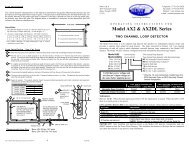
Figure 1. <strong>The</strong> interior of the <strong>620</strong>/<strong>640</strong> <strong>Barrier</strong> cabinet (for right-hand orientation)Using the <strong>Manual</strong> Release key to disengage the beamfrom hydraulic operation allows you to operate thebarrier by hand.You disconnect the hydraulic operation of the beam byturning the <strong>Manual</strong> Release key counterclockwise. <strong>The</strong>nyou can raise or lower the barrier by hand.Figure 2. For manual operation, use the <strong>Manual</strong>Release key to unlock the barrier<strong>Manual</strong> operation of the beam is important during theinstallation process and can be useful during powerinterruptions or failures.To re-engage the hydraulic operation of the barrier, turnthe key clockwise.6
E (Semi-Automatic) Mode<strong>The</strong> E (semi-automatic) mode of operation for the <strong>620</strong>and <strong>640</strong> <strong>Barrier</strong> is designed for users who want to signalthe barrier to either open (the beam rises) or close (thebeam lowers).Sending one activating signal to the beam causes it toopen and remain open until another activating signal issent. Sending a second activating signal lowers thebeam.<strong>The</strong> basic logic of E mode is enhanced to protect bothpeople and property if anything interrupts the beam’smovement. What happens after such an interruptiondepends on whether the barrier is opening or closingwhen the interruption occurs and depends on whetherthe interruption is a second signal or an obstacle in thebeam’s path.When a second signal interrupts opening, the beamstops. <strong>The</strong> beam does not move until yet another signalis sent. <strong>The</strong>n the beam closes.If an activating signal interrupts the beam duringclosing, the beam immediately reopens. A stop signalstops the movement of the beam.If something obstructs the beam’s closing for 30 sec orless, the beam stops its movement, though the motormay continue to run its entire cycle. Sending anothersignal causes the beam to reopen. If something obstructsthe beam's movement for more than 30 sec, the barrierbecomes jammed. You then have to reset the barrier fornormal hydraulic operation (see the subsection"Resetting the <strong>Barrier</strong>" below).WARNING! <strong>The</strong> pressure the beam applies to theobstruction is determined by the bypass valveadjustment. It is the installer's responsibility tomake sure the pressures for the closing and openingbeam are correctly set.Installing external reversing devices alters the logic of Emode operation in the following way: During theopening cycle, any triggered reversing device is ignored,that is, the beam continues its opening movement.During closing, a triggered reversing device causes thebeam to open or stop, depending on the pause count andwhether preflashing is selected (see page 8).A (Automatic) ModeNote: <strong>The</strong> A (automatic) mode of operation on the624 MPS control panel is not exactly the same asthe A mode on other FAAC control panels. On the624 MPS, the A mode includes some securityfeatures useful in barrier applications.<strong>The</strong> A (automatic) mode of operation for the <strong>620</strong> or <strong>640</strong><strong>Barrier</strong> is designed for users who want to signal thebeam once to open and then automatically close after aselected time.What happens when A mode operation is interrupteddepends on which part of the cycle is interrupted by asignal or obstruction. During the opening phase, asecond activating signal is ignored; a stop signal stopsthe beam; reversing devices do not affect the beam.During the pause phase, an activating signal causes thebeam to close; a stop signal or triggered reversingdevice discontinues the pause count (the beam will notmove until it receives an activating signal or thereversing device is no longer triggered).During the closing phase, an activating signal causes thebeam to reopen immediately; a stop signal stops themovement of the barrier beam (it will not move until itreceives another activating signal); a triggered reversingdevice opens or stops the beam, depending on the pausecount and whether preflashing is selected (see page 8).If the barrier beam has been stopped with a stop signal,additional signals have the following effects on thebeam. An activating signal causes the beam to recloseimmediately; another stop signal has no effect; and atriggered reversing device has no effect.If an obstacle interrupts A mode operation duringclosing for 30 sec or less, the beam stops its movement,though the motor may continue to run. If somethingobstructs the beam's movement for more than 30 sec,the barrier becomes jammed. You then have to reset thebarrier for normal hydraulic operation (see thesubsection "Resetting the <strong>Barrier</strong>" below).P (Parking) ModeWARNING! Do not connect reversing devices toyour control panel if the barrier is to operate in Pmode. P mode logic is not compatible with signalsfrom such devices. For photocells, loops, and otherN.C. reversing devices to operate properly in Pmode, you must install the optional 624 FSWElectronic Card.WARNING! Operating a <strong>620</strong> or <strong>640</strong> <strong>Barrier</strong> in Pmode without an attendant can be dangerous.<strong>The</strong>refore, we highly recommend the use of theoptional 624 FSW Card.<strong>The</strong> P (parking) mode of operation assumes you want tosignal the beam to open, close, or stop and assumes thata three button switch is installed, one button to open,one to close, and one to stop.In P mode, each switch button essentially performs itsfunction every time it is pressed. Sometimes this meansthe button has no effect. For example, pressing the openbutton when the beam is already opened has no effect.7
An apparent exception to the "you get what you press"logic is when the beam is opening and you press theclose button: <strong>The</strong> beam continues to open. However,once opened, the beam immediately closes. In otherwords, the system remembers the close command andresponds as soon as it can.R (Remote) ModeNote: <strong>The</strong> R mode of operation requires theinstallation of the 624 Slave Card.<strong>The</strong> R (remote) mode of operation is useful only inthose applications with two opposing beams that operatesimultaneously and that control very wide entrances.<strong>The</strong> R mode essentially suppresses one 624 MPScontrol panel so that the other can control both beams.Caution: Do not use R mode logic when you haveonly one barrier beam. Your one barrier will notoperate properly if it is set to R mode.In two-barrier applications, you set the one barrier(called the slave) to R mode and set the other barrier(called the master) to A, E, or P mode. Both beams thenoperate simultaneously according to the logic set on themaster barrier’s control panel.Resetting the <strong>Barrier</strong><strong>The</strong>re are two occasions when it is necessary to reset thebarrier for normal operation: after the operator has beenin jam status or after it has been in alarm status.To reset the operator, you can press the reset buttonlocated on the control panel (see Figure 6) to continuenormal barrier operation. An alternate and easier way toreset the barrier is to turn the main power supply off andthen on.Jam Status<strong>The</strong>re are situations in which the barrier beam canbecome jammed, when it will not respond to activatingsignals of any kind.If an obstruction or someone stops the beam'smovement as a limit switch is being triggered by thelimit switch plate (just as the barrier beam is starting itstravel), the motor times out and the operator does notknow how to interpret any incoming activating signal.<strong>The</strong> barrier beam will not move until the control panel isreset. Press the reset button on the control panel (seeFigure 6), or turn the main power off and then on.Alarm StatusAn emergency alarm device, such as a fire box, with anormally closed switch can be connected to terminals 4and 5 on the control panel. Sending an activating signalto such a device opens the barrier and keeps it open.Such an emergency signal puts the control panel inalarm status, and you must then reset the barrier to closethe barrier or to resume normal hydraulic operation.Press the reset button on the control panel (see Figure6), or turn the main power off and then on.8
E Logic: How the <strong>Barrier</strong> Beam BehavesBeam Signal and Its Effect on BeamStatus Open Stop ReversingDeviceEmergencyAlarmclosed opens no effect no effect beam opens (oropened closes* stops no effect remains open) andclosing opens stops opens or stops** warning lightflashes; all otheropening stops stops no effect functions arestopped closes* no effect no effect inhibited* With preflashing selected, the beam recloses after 5 sec; with no preflashing selected, the beam closes immediately.**With no preflashing selected, the beam opens immediately and requires another signal to close. With preflashingselected, the beam stops until the reversing is no longer triggered; then the beam opens.A Logic: How the <strong>Barrier</strong> Beam BehavesBeam Signal and Its Effect on BeamStatus Open Stop ReversingDeviceEmergencyAlarmclosed opens and closes no effect no effectafter pause timeopened closes* beam remains openuntil anotherstops; pause countis interrupted; whenactivating signalcloses beam*reversing device isno longer triggered,beam closes afterremaining pausecountbeam opens (orremains open) andwarning lightflashes; all otherfunctions areclosing opens stops opens or stops** inhibitedopening no effect stops no effectstopped closes* no effect no effect* With pre-flashing selected, the beam recloses after 5 sec; with no preflashing selected, the beam closes immediately.**With no preflashing selected, the beam opens immediately; when the reversing device is no longer triggered, the pausecount begins. With preflashing selected, the beam stops until the reversing device is no longer triggered; then the beamopens and begins its pause count.P Logic: How the <strong>Barrier</strong> Beam BehavesBeam Signal and Its Effect on BeamStatus Open Close Stop EmergencyAlarmclosed opens no effect no effect beam opens (oropened no effect closes no effect remains open) andclosing opens no effect stops warning lightflashes; all otheropening no effect closes after opening stops functions arestopped opens closes no effect inhibitedR Logic: How the <strong>Barrier</strong> Beam BehavesR logic insures the simultaneous operation of the two opposed beams across avery wide entrance. <strong>The</strong> slave barrier with R logic operates according to the A, E,or P logic set on the control panel of the master barrier.9
Installing the <strong>Barrier</strong> SystemWARNING! Do not install the barrier in such away that the beam moves within 2 feet (610 mm) ofa rigid object.Installing the <strong>620</strong> or <strong>640</strong> <strong>Barrier</strong> System consists of thefollowing general steps:Determining the orientation of the installationPreparing the forms for the concrete mountingslab and conduitMounting the cabinet on the concrete slabConnecting the main power source to theoperatorWiring the control panel for operational logicWiring additional accessories into the controlpanelDecreasing the hydraulic pressuresSetting the DIP switches on the control panelAttaching the barrier beamTesting the operation of the beamNote: <strong>The</strong> following installation instructionsassume you are fully capable of installing anelectronic barrier gate. This manual does notinstruct you in designing a gate, pouring the cementfoundation, or basic electrical wiring. <strong>The</strong>installation tasks discussed in this manual are taskspeculiar to the <strong>620</strong> and <strong>640</strong> <strong>Barrier</strong>s.Determine the Orientationof the <strong>Installation</strong>You first need to determine whether your operator is setup for a right-hand or left-hand installation (see Figure3). Either orientation is acceptable.Open the panel door of the operator cabinet with the keyprovided and lift the panel up and away from thecabinet, taking care not to disconnect the cabling to thefan (if installed). Look at the two pistons to see whichhas the compression spring surrounding it. Compareyour operator with Figure 3 and use the figure to helpyou determine the orientation of your installation.If your operator is not in the correct orientation, turningthe cabinet around 180 deg is the easiest way to solvethe problem. We suggest you call us if your installationsite cannot accommodate this solution since theorientation of the barrier can be changed with about anhour’s worth of work.Figure 3. Right-hand vs. left-hand installation of the <strong>620</strong>/<strong>640</strong> <strong>Barrier</strong>10
Prepare the Forms for theConcrete Slab and ConduitYou need to set the concrete forms to provide acement footing that is a minimum of 18 by 18 in.(46 by 46 cm) and that is poured a minimum of 18 in.(46 cm) below the ground level or just below the frostline, whichever is greater (see Figure 4). (Your soilconditions will also affect the size of the cementfooting.) To help prevent rust, the top of your cementfooting should be above ground level.Within the form boundaries you must locate theelectrical conduit so that it will protrude through thefoundation plate (the plate is provided as an option)and above the top of the foundation plate about1/2 in. (1.3 cm).<strong>The</strong> exact placement of the conduit is determinedpartly by the foundation plate you use and moreimportantly by the access holes in the bottom of theoperator cabinet (see Figure 5). If you choose tosupply your own foundation plate, be sure to use steelthat is 3/8 in. (1 cm) thick for the plate and be sure toprovide a hole large enough to accommodate your twoelectrical conduits, one for high-voltage wire and onefor low-voltage wire. In addition, your foundationplate needs four 1/2-in. (1-1/4 cm) anchor bolts thatextend at least 6-1/2 in. (16-1/2 cm) into the cementfooting. <strong>The</strong> anchor bolts should be positioned tomatch the holes in the bottom of your operator'scabinet.After the concrete is poured in the forms and before itsets, place the foundation plate in the cement so thatthe top of the plate is level and flush with the top ofthe cement.Allow the concrete to set a minimum of two full daysbefore you mount the operator cabinet.With the key provided, open the operator's panel doorand lift the door away from the cabinet. It may benecessary on your model of operator to disconnect thewiring to the fan on the panel door to allow you tomore easily handle the heavy cabinet.Set the operator cabinet on the foundation plate,aligning the holes in the bottom of the cabinet with thebolts and conduit protruding above the foundationplate. Bolt the cabinet to the foundation plate andcement footing. If necessary, reconnect the wiring tothe fan on the panel door.Before connecting the main power to your barrier, youmust remove the vent screw on the hydraulic powerpack. Midway along the top, left edge of the hydraulic1/2 in. (1-1/4 cm)ANCHOR BOLT,4 REQUIREDFOUNDATION PLATEGROUND LEVELGROUND LEVELMAIN POWERCONDUIT18 in.(45 cm)MINIMUMCEMENT FOOTINGCONTROL WIRECONDUIT18 in. (46 cm)MINIMUM TOFROST LINENOTES:Sizes shown are minimum dimensions.Wires for loop detectors, push buttons, activating devices, and so forth must bekept separated from the high voltage line.Figure 4. Concrete mounting slab, side view11
power pack is a hexagonal screw. Remove it now.Failure to remove the screw can result in erraticoperation of the barrier beam. Do not throw the screwaway in case you ever need to transport the barrier unitor its hydraulic power pack.Connect the Main Power<strong>The</strong> installer is responsible for providing a groundedcircuit protected by a circuit breaker from the mainpower source to the operator.Note: Your standard 220 VAC power sourcemeets the specification for 230 VAC, +6or -10%.All wiring should conform to applicable electricalcodes and all wiring and fittings should be weatherproofand/or suitable for burial.To connect the main power source to the barrier,remove the cover of the main power switch at the topof the inside of the barrier cabinet. <strong>The</strong>n run the mainpower wires from the base of the cabinet up throughflexible conduit that is on the cabinet door side of thesteel cross member. Run the wires and conduit throughthe connector on the right side of the junction box forthe main power switch. (see Figure 7)Caution: Do not run the main power conduit upthe metal channel in the right front of the cabinet.<strong>The</strong> right front channel houses wiring for the limitswitches and is appropriate only for low-voltagewiring.Figure 5. Dimensions of the optional FAAC <strong>620</strong>/<strong>640</strong> foundation plate12
J1J2J3J4J5J6J9P1TF1Low-voltage terminal stripHigh-voltage terminal stripLimit switch connectorDecoder connectorConnector for FSW, Slave, Relay boardsConnector for NTC probePower supply terminal stripReset pushbuttonTransformerDIP Switches:S1 Used to set operating logicS2 Used to set operating logicS3 Used to set pause timeS4 Used to set pause timeS5 Used to set pause timeS6 Used to set braking time, long or shortFuses:F1F2Capacitor:Status LEDs:FCC (DL6)FCA (DL5)OPEN (DL1)CLOS/FSW(DL2)STOP (DL3)ALARM (DL4)5 amps: fuse for operator motorand main power1.6 amps: fuse for accessories16 mFFigure 6. <strong>The</strong> 624 MPS Control PanelIlluminated except when gate isfully closedIlluminated except when gate isfully openedIlluminates only when receivingsignal to openIn A or E mode is illuminatedexcept when a reversing deviceis triggered. In P mode, this isilluminated only when receivingclose signalIlluminated except whenreceiving stop signalIlluminated except whenemergency signal is received(gate is open in emergency)13
Connect the main power ground wire to the groundscrew in the junction box. Connect the other wires tothe line side of the switch. <strong>The</strong> 624 MPS control panelis already connected to the load side of the main powerswitch.Caution: U.L. listing requires the use of flexibleconduit around the main power wiring from thebase of the barrier cabinet to the flexible conduitconnector on the junction box of the main powerswitch.Wire the Control Panel forOperational LogicWARNING! Turn the main power off before youmake any electrical connections or set anyswitches inside the control panel box.Any opening activating devices you install must havenormally open (N.O.) contacts. <strong>The</strong> required contactsfor your closing device vary according to the operatinglogic you want to use: A and E logic modes requireN.O. contacts, and P mode requires normally closed(N.C.) contacts. No matter which logic mode you use,all stop, reversing, and emergency activating devicesmust have N.C. contacts.In addition to connecting your activating devices foryour logical mode of operation (A, E, or P) toterminals 1, 2, and 3, you also have to set DIPswitches S1 and S2 to set the operating logic. (See thesection "Logical Operation" earlier in this manual for acomplete discussion of the logical operating modes.)A or E Mode OperationFor A or E mode operation, connect the activating,reversing, stop, and emergency devices as shown inFigure 7. If your activating device has separatenormally open (N.O.) contacts for both opening andclosing signals, connect both wires in parallel toterminal 1. Use terminal 5 or 6 for common for allactivating, reversing, stop, and emergency devices thatyou connect.P Mode OperationFor P mode operation, connect the opening, closing,stop, and emergency devices as shown in Figure 8.Note that the opening device must be of the normallyopen (N.O.) type, and that the closing, stopping, andemergency devices must be of the normally closed(N.C.) type. Use terminal 5 or 6 for common for thosedevices.WARNING! Do not wire reversing devicesdirectly to your control panel if the barrier is tooperate in P mode. P mode logic is not compatiblewith signals from such devices. For photocells,loops, and other N.C. reversing devices to operateproperly in P mode, you must install the optional624 FSW Electronic Card.WARNING! We highly recommend the use of anoptional 624 FSW Card if you are operating in Pmode to provide more protection for people andproperty.Wire Additional AccessoriesWARNING! Turn the main power off before youmake any electrical connections or set anyswitches inside the control panel box.WARNING! Do not connect reversing devices toyour control panel if the barrier is to operate in Pmode. P mode logic is not compatible with signalsfrom such devices. For photocells, loops, andother N.C. reversing devices to operate properly inP mode, you must install the optional 624 FSWElectronic Card.Wire additional accessories into your 624 MPSControl Panel as shown in Figures 6 and 7.Breaking the emergency device contacts to terminal 4automatically raises the beam. You then must reset thecontrol panel to operate the beam. To reset the controlpanel, cycle the main power off and on or press thereset button on the control panel (see Figure 6).Terminal 7 on the control panel provides 24 VDCcurrent and can be used to power accessories requiringsuch power.14
Figure 7. <strong>The</strong> wiring detail for the <strong>620</strong>/ <strong>640</strong> barrierDecrease the HydraulicPressuresWARNING! You must decrease the hydraulicpressures of the beam's opening and closingmomentum before you operate the barrierelectrically. <strong>The</strong> pressure valves are not preset atthe factory and may operate the beam with enoughforce to endanger people and seriously damage thebeam itself.Turning the screws counterclockwise decreases thepressure and turning them clockwise increases thepressure. <strong>The</strong> red screw sets the closing pressure, andthe green screw sets the opening pressure.Before operating the beam for the first time, decreasethe pressure of each valve. When you test your installedbarrier beam later, you will make final adjustments tothese pressure valves.<strong>The</strong> red and green screws located near the bottom of thehydraulic power pack are the bypass pressure valvesthat control the hydraulic pressure of the barrier beamwhen it opens and closes.15
Set the DIP SwitchesWARNING! Turn the main power off before youmake any electrical connections or set any switchesinside the control panel box.You need to set six different DIP switches before youoperate the barrier. <strong>The</strong> DIP switches control theoperating logic, the pause time, and the length of timefor braking.Operating LogicWARNING! Turn the main power off before youmake any electrical connections or set any switchesinside the control panel box.Switches S1 and S2 set the operating logic of the barrierbeam. (See the section "Logical Operation" earlier inthis manual for a complete discussion of the logicaloperating modes.) Use the following table to set yourswitches:SwitchLogic S1 S2A on onE off onP on offR off offCaution: Use R logic only in an application withtwo opposed barrier beams. Set only one controlpanel to R logic; set the other control panel to A, E,or P.Pause TimeWARNING! Turn the main power off before youmake any electrical connections or set any switchesinside the control panel box.<strong>The</strong> DIP switches S3, S4, and S5 allow you to set thetime in seconds for how long the barrier beam pauseswhen it is fully opened before it closes in A mode. Inaddition, if you have a warning light installed on yourbarrier system and you are operating in A or E mode,you can use these DIP switches to have the warninglight flash for the last 5 sec of the pause time before thegate closes. (P mode does not allow preflashing of awarning light.)Pause time,Switchsec S3 S4 S50 off off off5 on off off10 off on off20 on on off10 off off on20 on off on30 off on on40 on on on<strong>The</strong> shaded selections flash any connected warninglight for the last 5 sec of the pause time. Note that Plogic does not allow preflashing.Braking TimeWARNING! Turn the main power off before youmake any electrical connections or set any switchesinside the control panel box.DIP switch S6 allows you to choose a long or shortbraking time. Turn S6 off for a short braking time (1.5sec). Turn S6 on for a long braking time (2.5 sec).Whether you should choose a short or long braking timedepends on the interaction of DIP switch S6 and thebraking control of the limit switches (see Figure 9). <strong>The</strong>length and type of your barrier beam is the mostimportant factor in this decision. For example, allskirted beams require a long braking time. All other <strong>620</strong>barriers will operate best with a short braking time. All<strong>640</strong> barrier beams operate best with a long braking time.Braking cannot begin until a limit switch is triggered.You can adjust the placement of either limit switch plateso that it triggers its switch sooner or later in the beam's90-deg travel (see Figure 9). <strong>The</strong> switch and switchplate on the same side of the cabinet as the compressionspring control the closing brake; the switch and switchplate on the other side of the operator cabinet control theopening brake.To move a limit switch plate, loosen the Allen screwsholding the plate and then slide the plate. For longerbraking, slide the plate toward its switch; for shorterbraking, slide the plate away from its switch. <strong>The</strong>nretighten the Allen screws that secure the limit switchplates.Use the following table to set your switches for thepause time:16
Figure 8. Limit switch plates and mechanical stops on a right-hand barrierIn choosing a long or short braking time, keep thefollowing in mind.DIP switch S6 sets one braking time for both theopening and the closing.<strong>The</strong> longer the barrier beam, the easier is it on thebeam if braking begins sooner.It does not hurt the operator if the motor continuesto run after the barrier beam is fully opened orfully closed.If the motor stops running before the beam fullyopens or closes, then choose a long braking time(switch S6 is on) and/or adjust the limit switches.Attach the <strong>Barrier</strong> BeamWARNING! Do not install the barrier in such away that the beam moves within 2 feet (610 mm)of a rigid object.Before you attach the barrier beam, be sure you havedisconnected the barrier from hydraulic operation bymeans of the <strong>Manual</strong> Release mechanism (turn the keycounterclockwise).Next you attach the beam to the operator cabinet withthe beam in a vertical position. See Figure 10 if youare attaching an aluminum beam to a model <strong>620</strong>operator and see Figure 11 if you are attaching analuminum beam to a model <strong>640</strong> operator. (Woodenbeams require additional sandwich plates for mountingthe beam to the barrier cabinet.)Figure 9. Attaching an aluminum beam to the<strong>620</strong> <strong>Barrier</strong>Test the Operationof the BeamCheck the Mechanical StopsFirst, be sure the hydraulic operation of the beam isstill disengaged (the <strong>Manual</strong> Release key should beturned counterclockwise). Next, move the beam byhand from the fully opened position (vertical) to thefully closed position (horizontal) and back to the fullyopened position. If the positions are not perfectlyvertical and perfectly horizontal, then adjust themechanical stops as necessary (see Figure 9).17
If the beam drifts toward the closed position, turn theadjuster nut (shown in Fig. 1) clockwise to tighten thecompression spring.If the beam drifts toward the opened position, turn theadjuster nut (shown in Fig. 1) counterclockwise toloosen the compression spring..Note: Proper adjustment of the spring willcounterbalance the beam. This will allow theminimal pressure setting necessary to move thebeam.Adjust the Bypass ValvesNow that the beam is attached, re-engage the hydraulicoperation of the barrier by rotating the <strong>Manual</strong> Releasekey clockwise.Figure 10. Attaching an aluminum beam to the<strong>640</strong> <strong>Barrier</strong>Check the Compression Spring<strong>The</strong> compression spring should be adjusted so that itholds the beam in any position that it is placed while inmanual mode. (<strong>Manual</strong> mode is discussed on pages 5and 6 and shown in Fig. 2)Move the beam by hand to a half-opened position. <strong>The</strong>beam should stay there when you remove your hand.Note: All compression spring adjustments shouldbe made with the beam in the vertical (open)position.Send an activating signal to the barrier. <strong>The</strong> signalshould open the barrier. If it does not open, increasethe pressure of the opening bypass valve (the greenvalve) by turning the screw clockwise in small, 1/8-turn increments until the beam does open.Test the closing of the barrier in the same way. If thebeam fails to move in the closing direction, thenincrease the pressure of the closing bypass valve (thered valve) by turning the screw clockwise in smallincrements until the beam does close.Remember that you should set the bypass pressurevalves so that the beam works with the least pressurenecessary. It is a safety feature of the barrier that thebeam should apply no more than about 33 lb (15 kg)force against any obstacle it might encounter.WARNING! For maximum safety to people andproperty, use photoeyes and other non-contactreversing devices in addition to adjusting thebypass pressure valves to the minimum settings.18
Optional <strong>Installation</strong>sInstalling the EmergencyBypass SolenoidWARNING! Turn the main power off before youmake any electrical connections or set anyswitches inside the control panel box.<strong>The</strong> emergency bypass solenoid automaticallydisengages the hydraulic system of the barrier beamwhen the main power is not available. This allows thebarrier to be raised by hand so that people and vehiclescan safely pass during power interruptions andfailures.After connecting the solenoid, you need to connect thehydraulic lines between the operator and the pistons.How you connect the lines depends on the orientationof your barrier installation (see Figure 13).Finally, connect the solenoid to your main power lineso that it can sense when power is or is not available(see Figure 14).(a) Right-hand orientationNote: Once the emergency bypass solenoid hasdisengaged the hydraulic system and once youhave raised the beam by hand, you cannot lowerthe barrier beam until the power is restored.If you are installing the optional emergency bypasssolenoid, you must first turn off the main power anddisengage the hydraulic system by using the <strong>Manual</strong>Release key.<strong>The</strong>n you disassemble the hydraulic lines between thepistons and the operator so that you can install newhydraulic pipe fittings.After installing the new pipe fittings, install theemergency bypass solenoid (see Figure 12).(b) Left-hand orientationFigure 12. Connect the hydraulic linesFigure 11. Install the solenoidRe-engage the hydraulic system with the <strong>Manual</strong>Release key so that you can test the installed solenoid.19
To test the solenoid, turn off the power to the barrier.If the solenoid works, you should be able to raise thebeam but not lower it after raising it. You should beable to lower the beam only after turning the powerback on.Installing OptionalElectronic CardsThree optional electronic cards enhance the versatilityof the FAAC <strong>620</strong> and <strong>640</strong> <strong>Barrier</strong>s. <strong>The</strong> cards featurethe same reliable surface-mount technology as ourelectronic control panels and feature easy installation.You just plug the 624 Slave Card, the 624 FSW Card,or the 624 Relay Card into the 20-pin connector portnext to the DIP switches on the main 624 MPS controlpanel (see Figure 6).Installing the 624 Slave Card requires the following.WARNING! Turn the main power off before youmake any electrical connections or set anyswitches inside the control panel box.First, you must choose one of the two 624 MPScontrol panels to be the master control panel. <strong>The</strong>other 624 MPS control panel (the slave 624 MPScontrol panel) is controlled by the master.On the master control panel, you then set the DIPswitches for the logic (A, E, or P), pause time, andbraking time that you want. Both barrier beams willbehave according to these settings on the master 624MPS control panel.In addition, if you want two or more of the newoptional Cards, you just stack the optional cards ontop of one another with the 624 Relay Card always theuppermost card (see Figures 14 and 17).<strong>The</strong> 624 Slave Card<strong>The</strong> optional 624 Slave Card enables two opposingbarriers to operate simultaneously, preventing any lagtime between the beams when you signal the operatorsto open. Generally, only very wide entrances make useof two opposing barriers, but those applications oftenrequire the capabilities of the 624 Slave Card forsmooth traffic control, aesthetics, and safety reasons.In such an application, you must set up 3 differentcircuit boards:Figure 13. Connect the solenoid to the mainpower supply lineMaster 624 MPS control panel: This is the controlpanel on one of the two barriers.Slave 624 MPS control panel: This is the controlpanel on the other of the two barriers.624 Slave Card: This is the optional electroniccard that is plugged into the master 624 MPScontrol panel.Figure 14. How the 624 Slave Card or 624 FSWCard plugs into the main 624 MPS controlpanel20
Next, you electrically connect the master 624 MPScontrol panel for the logic you have set on DIPswitches S1 and S2 (see Figures 6 and 7).<strong>The</strong>n you plug the 624 Slave Card into the 20-pinconnector port on the master 624 MPS control panel.Make sure it is well seated in the port.If you have set the logic on the master 624 MPScontrol panel to P mode, then you must cut jumperLK1 on the 624 Slave Card.Next, you connect the 624 Slave Card to the slave 624MPS control panel using 20 AWG wire according tothe scheme shown in Figure 16.Finally, on the slave 624 MPS control panel, set boththe S1 and S2 DIP switches to off for R logic. <strong>The</strong>master MPS control panel ignores all other DIP switchsettings on the slave 624 MPS control panel.Figure 15. Wiring diagram for the 624 Slave Card21
<strong>The</strong> 624 FSW Card<strong>The</strong> optional 624 FSW Card enables reversing devicesto work when the barrier is operating in P (parking)mode. Useful in revenue parking applications, theFSW Card maintains the revenue generating situationwhile insuring that the beam doesn't harm potentialtailgaters. <strong>The</strong> option allows a reversing device tointervene while the beam is closing to stop beammotion. <strong>The</strong> beam finishes closing when the reversingdevice is no longer triggered.Note: <strong>The</strong> optional 624 FSW Card does not workwith 624 MPS control panels of revision level 0.Such control panels have the DIP switches in themiddle of the board rather than on the edge of theboard. You can verify the revision level of yourcontrol panel by checking the position of the DIPswitches or by looking on the bottom side of theboard (revisions are numbered 00 or 01, forexample).Installing the optional 624 FSW Card requires thefollowing.WARNING! Turn the main power off before youmake any electrical connections or set anyswitches inside the control panel box.First, plug the 624 FSW Card into the 20-pinconnector port on the main 624 MPS control panel.Make sure the card is well seated. <strong>The</strong>n connect theterminals on the 624 FSW Card to the 624 MPScontrol panel as shown in Figure 17. Use 20 AWGwire to make the connections.<strong>The</strong> LEDs on the 624 FSW Card have the followingfunctions when the card is connected.LED Lighted Not LightedDL1 Stop deactivated Stop activatedDL2 Close activated ClosedeactivatedDL3Reversing device notactivatedReversingdeviceactivatedFigure 16. Wiring diagram for the 624 FSW Card22
<strong>The</strong> 624 Relay Card<strong>The</strong> optional 624 Relay Card provides six normallyopen (N.O.) electrical contacts for connectingauxiliary equipment, such as remote monitors,counters, computers, lighting controls, and so forth.<strong>The</strong> Relay Card is much more convenient to use thanstandard relays and has the advantage of fitting neatlyin the control panel enclosure.Installing the 624 Relay Card requires the following.WARNING! Turn the main power off before youmake any electrical connections or set anyswitches inside the control panel box.First, plug one end of the flat cable into the Relay Cardas shown in Figure 18. <strong>The</strong>n mount the Relay Card tothe transformer of the main control panel using the flatcable, spacers and screws provided (see Figure 18).Next plug the flat cable into the 20-pin connector porton the main control panel. Make sure the connectingends of the flat cable are well seated.Figure 17. How the 624 Relay Card plugs intothe 624 MPS control panelEach numbered terminal on the Relay Card (forexample, RL1; see Figure 19), along with the commonterminal (COM), provides a normally open contact.Each contact has a maximum rating of 1 amp for a 24VDC accessory or 1 /2 amp for a 120 VAC accessory.Each contact closes under a certain condition (see thetable below).Relay TerminalRL1RL2RL3RL4RL5RL6Beam Status WhenRelay Contact ClosesStoppedOpenedClosedOpeningClosingAlarm status<strong>The</strong>se six sets of contacts can be used with the variousaccessories and auxiliary equipment common toparking and revenue generating applications.<strong>The</strong> 624 Relay Card has a number of LEDs thatfunction in addition to the LEDs on the main 624 MPScontrol panel. <strong>The</strong> Status LEDs are not illuminatedunless a particular condition exists. <strong>The</strong> table to theright lists the condition that makes these LEDsilluminate.Figure 18. <strong>The</strong> 624 Relay CardStatus LEDCHIUDEAPRECHIUSOAPERTOFERMOCondition CausingIlluminationBeam is closingBeam is openingBeam is closedBeam is openedBeam is stopped23
<strong>The</strong> Alarm LEDs are also not illuminated unless aparticular condition exists. When an Alarm LED islighted, you must do both of the following:(1) Correct the condition causing the LED toilluminate.(2) Reset the barrier in order to resume normal barrieroperation.To reset the barrier, turn the power off and then on orpress the Reset button on the main 624 MPS controlpanel.<strong>The</strong> table below lists the condition that makes eachAlarm LED illuminate.Alarm LEDERR-SY*ERR-TOERR-FCTEMP.Condition Causing IlluminationMicroprocessor errorSafety timer errorLimit switch errorMotor shut down because oftemperatureALL-OUT** Emergency device input enabled* When you have a 624 Slave Card installed, thisilluminated LED indicates that there is a problem withthe Slave Card connection.** If you have cut jumper LK1 on the Relay Card, thisLED will illuminate but the contact will not close.Four additional LEDs are always illuminated unlessthere is a problem in the circuits of the 624 Relay Carditself. FAAC personnel may ask you about these LEDsso the following table is included here. However, youmust send the board to us to be repaired.Circuit Status LEDProblem+5 V Voltage regulatorsVRLVOPTVACCRelay secondary powerOpto-isolator powerAccessory secondary powerChanging the Length orType of <strong>Barrier</strong> BeamWARNING! Do not install the barrier in such away that the beam moves within 2 feet (610 mm)of a rigid object.Changing the length or type of the barrier beamrequires installing a different barrier beam of thedesired length (and/or type) and requires making sureyou have the correct compression spring (designed fora particular weight of beam) for the barrier beam.<strong>The</strong> installer is responsible for making sure that thecompression spring is the correct spring for the barrierbeam.<strong>The</strong> following tables show which springs are designedfor various beam types and lengths. To check for thepart number of the compression spring in youroperator cabinet, check the tag attached to the spring.If it is necessary for you to replace the spring in acabinet with another compression spring, do thefollowing. First, turn off the main power to theoperator and then open the cabinet panel. Turn the<strong>Manual</strong> Release key counterclockwise. <strong>The</strong>n move thebeam by hand to the fully opened position.Unbolt the piston with the compression spring fromthe rocker arm. <strong>The</strong>n very carefully unscrew the capholding the compression spring with the spannerwrench to disengage the spring from the piston.Remove the spring from the piston.Install the correct compression spring by placing itover the piston and screwing it into place. <strong>The</strong>n reboltthe piston to the rocker arm and reinstall the steel crossmember. Re-engage the hydraulics by turning the<strong>Manual</strong> Release key clockwise.Be sure to recheck the tension of the compressionspring before you turn on the main power to theoperator. <strong>The</strong>n be sure to adjust the hydraulicpressures.24
Rigid Beams: Part Numbers of Compression Springs for Various LengthsBeam and RequiredSpring<strong>620</strong> <strong>Barrier</strong> Systems <strong>640</strong> <strong>Barrier</strong> SystemsRedwood Beam, ft 8–10 12–14 16 NA 16–18 18–20 20 NARigid Aluminum Beam,ft (m) 6 (2) 8 (2 1/2) 10 (3) 13 (4) 13 (4) 16 (5) 20 (6) 23 (7)FAAC Part No. forCompression Spring 721085 721069 721070 721072 721073 721074 721075 721080Skirted Beams: Part Numbers of Compression Springs for Various LengthsBeam and RequiredSpring<strong>620</strong> <strong>Barrier</strong> Systems <strong>640</strong> <strong>Barrier</strong> SystemsSkirted AluminumBeam, ft (m) 6 (2) 8 (2 1/2) 10 (3) 13 (4) 13 (4) 16 (5) 20 (6) 23 (7)FAAC Part No. forCompression Spring 721069 721071 721073 721074 721079 721080 721081 721082MaintenanceRegular MaintenanceInspect and service your <strong>620</strong> or <strong>640</strong> <strong>Barrier</strong> systemanytime you observe or suspect a malfunction of thebarrier. In addition, FAAC recommends you check thebarrier system every 1,000,000 cycles of the operatorfor the items listed below to keep your operator in thebest working condition. Failure to observe theserecommendations could compromise the functionalityof the operator.Special MaintenanceInspect and service your <strong>620</strong> or <strong>640</strong> <strong>Barrier</strong> systemanytime you observe or suspect a malfunction of thebarrier. In addition, if your observations warrant it,FAAC recommends you make the following listedrepairs and replacements to the barrier system to keepyour operator in the best working condition. Failure toobserve these recommendations could compromise thefunctionality of the operator.Item to Check Every1,000,000 CyclesEntire barrier systemOil levelBypass valvesBeam motionCooling fanControl panelWhat to DoReplace any visuallyobvious defective partRefill the oil if necessaryTighten or loosen thevalves to maintain therecommended pressuresettingsAdjust the compressionspring if necessaryClean the motor coolingductsTest the function of inputpower and output functionof all attached relays,cards, and devicesPart(s) to Repair orReplaceDrive pistons: seals andgasketsBall joints in the rockerarmNumber of Cycles1,000,0001,000,000Mechanical stops 1,000,000Hydraulic unit: seals andgaskets2,000,000Cooling fan 2,000,000Balancing spring 3,000,000Limit switches 6,000,00025
TroubleshootingWARNING! Turn the main power off before you make any electricalconnections or set any switches inside the control panel box.Problem: <strong>The</strong> beam is closed and won't open inresponse to an activating signal.Solution:Make sure the hydraulic operation of the barrier beamis engaged: <strong>The</strong> <strong>Manual</strong> Release key should be turnedclockwise.<strong>The</strong> OPEN indicator LED should illuminate when yousend an activating signal. If it does not, temporarilyshort terminals 1 and 5. If the short causes the beam toopen, then the problem exists in the activating deviceitself.If you have no stop device wired to terminal 3, thenmake sure you have a jumper installed betweenterminals 3 and 5 on the control panel. <strong>The</strong> STOP LEDshould be on.<strong>The</strong> FCC indicator light on the control panel shouldnot be illuminated. If it is illuminated, then the gate isnot fully closed. Adjust the position of the closinglimit switch plate.Try increasing the opening hydraulic pressure in smallincrements by turning the opening bypass valve screw(the green valve) clockwise.Verify that you have the correct compression springfor your barrier beam. If you have the correct spring,check that the spring will hold the beam in anyposition during manual operation. If the spring doesn'thold the beam in any position, try tightening thecompression spring until the beam is held and thenrecheck the hydraulic operation of the beam.Problem: <strong>The</strong> beam is open and won't close inresponse to an activating signal.Solution:Check the LEDs on the control panel. <strong>The</strong> FCA lightshould be off, and the CLOS/FSW, STOP, FCC, andALARM lights should be on.If the FCA light is on, then the gate is not fullyopened. Move the opening limit switch plate closer tothe opening switch sensor.If you have no reversing devices installed and you areoperating in A or E mode, make sure you have ajumper installed between terminals 2 and 5. (<strong>The</strong>CLOS/FSW light should be on.)If the CLOS/FSW light is off, some reversing deviceyou have installed is being continuously triggered andis preventing the beam from closing. Check yourreversing devices.If your activating device has two buttons—one foropening/closing and one for stop—and you areoperating in P mode, then make sure you have ajumper between terminals 2 and 5.If you have no stop device wired to terminal 3, thenmake sure you have a jumper installed betweenterminals 3 and 5 on the control panel.If you have no emergency device wired to terminal 4,then make sure you have a jumper installed betweenterminals 4 and 5 on the control panel.Increase the pressure of the closing bypass valve (thered valve) by turning the screw clockwise in smallincrements to see if the beam needs more hydraulicpressure for the closing direction.Problem: <strong>The</strong> beam is half opened and will neitheropen nor close in response to the activating device.Solution:<strong>The</strong> barrier may be in jam status because something orsomeone has physically prevented the beam fromopening or closing. Reset the barrier and then trysending another activating signal.Check the CLOS/FSW indicator light. It should be on.If it is not illuminated, then check the wiring on yoursafety devices.26
Limited WarrantyTo the original purchaser only: FAAC International, Inc., warrants, for twenty-four (24) months from the date of invoice, thegate operator systems and other related systems and equipment manufactured by FAAC S.p.A. and distributed by FAACInternational, Inc., to be free from defects in material and workmanship under normal use and service for which it was intendedprovided it has been properly installed and operated. FAAC International, Inc.'s obligations under this warranty shall be limited tothe repair or exchange of any part of parts manufactured by FAAC S.p.A. and distributed by FAAC International, Inc. Defectiveproducts must be returned to FAAC International, Inc., freight prepaid by purchaser, within the warranty period. Items returned willbe repaired or replaced, at FAAC International, Inc.'s option, upon an examination of the product by FAAC International, Inc.,which discloses, to the satisfaction of FAAC International, Inc., that the item is defective. FAAC International, Inc. will return thewarranted item freight prepaid. <strong>The</strong> products manufactured by FAAC S.p.A. and distributed by FAAC International, Inc., are notwarranted to meet the specific requirements, if any, of safety codes of any particular state, municipality, or other jurisdiction, andneither FAAC S.p.A. or FAAC International, Inc., assume any risk or liability whatsoever resulting from the use thereof, whetherused singly or in combination with other machines or apparatus.Any products and parts not manufactured by FAAC S.p.A. and distributed by FAAC International, Inc., will carry only thewarranty, if any, of the manufacturer. This warranty shall not apply to any products or parts thereof which have been repaired oraltered, without FAAC International, Inc.'s written consent, outside of FAAC International, Inc.'s workshop, or altered in any way soas, in the judgment of FAAC International, Inc., to affect adversely the stability or reliability of the product(s) or has been subject tomisuse, negligence, or accident, or has not been operated in accordance with FAAC International, Inc.'s or FAAC S.p.A.'sinstructions or has been operated under conditions more severe than, or otherwise exceeding, those set forth in the specifications forsuch product(s). Neither FAAC S.p.A. or FAAC International, Inc., shall be liable for any loss or damage whatsoever resulting,directly or indirectly, from the use or loss of use of the product(s). Without limiting the foregoing, this exclusion from liabilityembraces a purchaser's expenses for downtime or for making up downtime, damages for which the purchaser may be liable to otherpersons, damages to property, and injury to or death of any persons. Neither FAAC S.p.A. or FAAC International, Inc., assumes norauthorizes any person to assume for them any other liability in connection with the sale or use of the products of FAAC S.p.A. orFAAC International, Inc. <strong>The</strong> warranty hereinabove set forth shall not be deemed to cover maintenance parts, including, but notlimited to, hydraulic oil, filters, or the like. No agreement to replace or repair shall constitute an admission by FAAC S.p.A. orFAAC International, Inc., of any legal responsibility to effect such replacement, to make such repair, or otherwise. This limitedwarranty extends only to wholesale customers who buy directly through FAAC International, Inc.'s normal distribution channels.FAAC International, Inc., does not warrant its products to end consumers. Consumers must inquire from their selling dealer as to thenature and extent of that dealer's warranty, if any.This warranty is expressly in lieu of all other warranties expressed or implied including the warranties ofmerchantability and fitness for use. This warranty shall not apply to products or any part thereof which havebeen subject to accident, negligence, alteration, abuse, or misuse or if damage was due to improper installationor use of improper power source, or if damage was caused by fire, flood, lightning, electrical power surge,explosion, wind storm, hail, aircraft or vehicles, vandalism, riot or civil commotion, or acts of God.FAAC International, Inc.303 Lexington AvenueCheyenne, WY 82007 <strong>620</strong>/<strong>640</strong> IM, 4/00