lae Electronic - MTW 11-12
lae Electronic - MTW 11-12
lae Electronic - MTW 11-12
- No tags were found...

You also want an ePaper? Increase the reach of your titles
YUMPU automatically turns print PDFs into web optimized ePapers that Google loves.
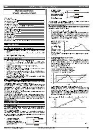
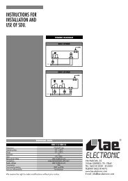
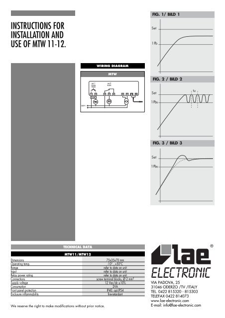
<strong>MTW</strong>../1 is a controller which allowstemperature control in ON/OFF mode withhysteresis or P.I.D. with output activation timemodulation. Version /2 offers a second output,controlled in ON/OFF mode with hysteresis,which is used for alarm, 2nd threshold etc.1 INSTALLATION1a The instrument is secured to the panel fromthe rear by means of the suitable brackets. lfusing the rubber gasket (vers.”S”), this must beinterposed between the instrument bezel and thepanel, checking the perfect adhesion carefully.1b For proper functioning, the instrumentneeds an ambient temperature between-10°...+50°C and 15%...80% relative Humidity.To improve protection of the probe againstelectro-magnetic interference, which mightcompromise its function, place its cable and thecontroller away from power lines.1c Outputs, power supply and probe must beconnected strictly following the diagram on theenclosure, where the maximum switching loadsand supply voltage are indicated, too. Theprobe screen must not be connected to anyother leads. If the external transformer isneeded, the instrument must be powered by thesuitable transformer supplied by LAE (mod.TR...).CAUTION!: If the relay switches a large load frequently,we suggest you contact us to obtain information aboutthe relay contact life.Caution: where delicate or valuable products have to bemaintained in special conditions, the same instrumentshould not be used for both control and limit functions. Insuch cases a separate instrument for each function isrecommended.2 FUNCTIONING DESCRIPTIONIn the basic functioning, the display shows thetemperature measured by the probe and, bymeans of the respective LED’S, the output status.2a To display the setpoint assigned to theoutput “out 1”, press key ; to change itsvalue, while you keep it pressed, push key orkey .2b To display the setpoint assigned to theL2output “out 2”, press key and act as per 2a.2c If an overrange or a probe failure occurs,“lor” is displayed and the outputs will work asprogrammed with the parameters 1PF and 2PF.3 SETUP<strong>MTW</strong>Through the setup it’s possible to configure theinstrument in such a way as to obtain thedesired functioning. Access to it is possibleby sequentially pressing keys + + andkeeping them pressed for 3 seconds.The available parameters are the following:1Lo: -199...999°C minimum programmablesetpoint for out <strong>11</strong> hi:1Lo...999°C maximum programmablesetpoint for out <strong>11</strong>hY:-100...100°K switching hysteresis for out1*1Pb:-<strong>12</strong>5...<strong>12</strong>5°K band of proportionalcontrol for out 1*1it: 00...999 sec. integrative action time forout 1*1dt:00...999 sec. derivative action time forout 1*1Ar:00...100% integrative action reset,referred to the Proportional band of out <strong>11</strong>ct: 01...255 sec. cycling time of out <strong>11</strong>PF: 00...01 status of out 1 with probe failureor overrange (00=off; 01 =on)2Lo: -199...999°C minimum programmablesetpoint for out 22hi: 2Lo...999°C maximum programmablesetpoint for out 22hY: -100...100°K switching hysteresis for out 22ct: 01...255 sec. cycling time of out 22PF: 00...01 status of out 2 with probe failureor overrange (00=off 01 =on)dPS: 00... 01 DON’T CHANGE !The parameters marked with (*) regardproportional control of out 1; access to them ispossible by choosing 00 for 1hY.3a To select the desired parameter press key. To display its value press key and ifnecessary change via key or key ; store itwith key . No key activation within 10seconds approx. causes the instrument to switchover to the basic functioning.3b The parameters 1ct and 2ct allow theprogramming of the minimum ON/OFF time.Ex. if 1ct = 60 seconds, after the switching ofthe out 1, this will remain in the new status forat least the programmed time, regardless of thetemperature.3c The positive or negative sign of theparameters 1hY, 1Pb, 2hY determines eitherheating (-) or cooling (+) control of therespective output.3d The outputs are switched OFF for anundetermined time, individually or both, bychoosing the value 00 for the parameters 1hYand 1Pb (out 1) and/or 2hY (out 2).3e lf the result of values assigned to setpointand hysteresis (proportional band) exceeds therange of the instrument, the outputs willpromptly switch OFF.Ex. setpoint = -150°C, proportional band =-100°K; or setpoint 990°C with hysteresis =+20°K.3f The values for the P,I,D actions should besuitably determined in order to minimisedeviation between the controlled temperatureand the setpoint also in response to alterationoccuring within the control loop. There arevarious ways to calculate them; here below wegive you an empirical method which is effectivein most cases. Proceed to programming of thefollowing values:1Pb = a sufficiently wide value (max.)1it = 1dt = 001Ar = 1001ct = if the system is very quick, set 3-5sec.After programming, start control. Whentemperature stabilises within the proportionalband (fig. 1), reduce its value until a regularhunting (Pbu) occurs and take note of thehunting period (tu) (fig. 2). Calculate the valuefor the parameters P,I,D by applying thefollowing formula:1Pb = Pbu *1.61it = tu *21dt = tu *0.<strong>12</strong>5In case of a temperature overshoot, reduce thevalue of 1Ar (fig. 3).4 CALIBRATIONShould it be necessary to recalibrate theinstrument or alter the displayed value, proceedas follows:4a Switch off the unit; press key andsimultaneously, power the unit again.4b 0°C calibration: when the temperature ofthe probe is between -30°...+30°C, press keyand , “0Ad” appears; by keeping keypressed , with keys or change accordingto necessity.4c High temperature calibration: when thetemperature of the probe is higher than 400°C,press key and , “SAd” appears; bykeeping key pressed , with keys orchange according to necessity.Attention: when this operation is carried out,you must bear in mind that 0°C calibrationcauses an offset all over the range, while spancalibration (high temperature) causes aproportional deviation. Ex. if an offset of -10°Cat 0° is set, this will cause a constant deviationall over the range. lf a correction of -02°C at400°C is set, at a temperature of 200°C thedeviation will be -01°C.When the operation is over, switch off the unit.WARRANTYLAE electronic Srl warrant that their products are free ofany defects in workmanship and materials for a period of 1(one) year from date of production shown on the enclosure.LAE electronic Srl shall only repair or replace thoseproducts of which defects are due to LAE electronic Srl andrecognised by their technicians. LAE electronic Srl are notliable for damages resulting from malfunctions of theproducts.Defects due to exceptional operating conditions,misapplication and/or tampering will void the warranty.All transport charges for returning the product to themanufacturer, after prior authorisation by LAE electronicSrl, and for the return to the purchaser are always for theaccount of the purchaser.