MLZ-MLM Refrigeration Scroll Compressors - HVAC and ...
MLZ-MLM Refrigeration Scroll Compressors - HVAC and ...
MLZ-MLM Refrigeration Scroll Compressors - HVAC and ...

You also want an ePaper? Increase the reach of your titles
YUMPU automatically turns print PDFs into web optimized ePapers that Google loves.
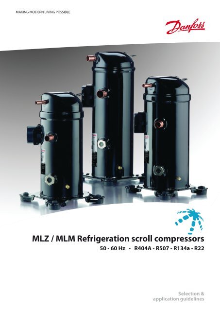
MAKING MODERN LIVING POSSIBLE<strong>MLZ</strong> / <strong>MLM</strong> <strong>Refrigeration</strong> scroll compressors50 - 60 Hz - R404A - R507 - R134a - R22Selection &application guidelines
Application guidelinesContentsSpecific application recommendations..................................................................................... 30Low ambient application.............................................................................................................................................30<strong>Scroll</strong> <strong>and</strong> reciprocating...............................................................................................................................................30Low load operations......................................................................................................................................................31Brazed plate heat exchangers....................................................................................................................................31Water utilising systems.................................................................................................................................................31Sound <strong>and</strong> vibration management.......................................................................................... 32Starting sound level......................................................................................................................................................32Running sound level.....................................................................................................................................................32Stopping sound level....................................................................................................................................................32Sound generation in a refrigeration system.........................................................................................................32Compressor sound radiation......................................................................................................................................32Mechanical vibrations..................................................................................................................................................33Gas pulsation...................................................................................................................................................................33Installation......................................................................................................................... 34System cleanliness.........................................................................................................................................................34Compressor h<strong>and</strong>ling <strong>and</strong> storage..........................................................................................................................34Compressor mounting.................................................................................................................................................34Compressor holding charge.......................................................................................................................................34Tube brazing procedure..............................................................................................................................................34Brazing material..............................................................................................................................................................34Vacuum evacuation <strong>and</strong> moisture removal..........................................................................................................35Liquid line filter driers...................................................................................................................................................36Refrigerant charging.....................................................................................................................................................36Insulation resistance <strong>and</strong> dielectric strength.......................................................................................................36Ordering information <strong>and</strong> packaging..................................................................................... 37Packaging..........................................................................................................................................................................37Packaging details...........................................................................................................................................................37Single pack........................................................................................................................................................................38Industrial pack.................................................................................................................................................................39Spare parts & accessories..................................................................................................... 40Run capacitors for PSC wiring....................................................................................................................................40Start capacitors <strong>and</strong> starting relay for CSR wiring..............................................................................................40Rotolock adaptor set.....................................................................................................................................................40Rotolock adaptor............................................................................................................................................................40Crankcase heater............................................................................................................................................................41Discharge temperature protection..........................................................................................................................41Magnetic discharge non return valve ....................................................................................................................41Lubricant...........................................................................................................................................................................41Mounting hardware......................................................................................................................................................42IP54 upgrade kit .............................................................................................................................................................42Acoustic hood .................................................................................................................................................................42FRCC.PC.015.A3.02 3
Application guidelinesFeaturesWith its unique scroll design <strong>and</strong> manufacturingprocess flexibility, the new Danfoss <strong>MLZ</strong>/<strong>MLM</strong> refrigerationcompressor offers a highly efficient solutionfor dem<strong>and</strong>ing refrigeration applications.This new family of refrigeration compressors includes11 sizes of medium temperature scroll compressorsdesigned for commercial refrigerationapplications. These compressors are engineeredfor refrigeration, <strong>and</strong> offer cooling capacity from3.4 to 21 kW (2 to 10 HP) at common voltages <strong>and</strong>frequencies as well as any of the common refrigerants(R404A - R134a - R507 - R22).Thanks to its dedicated refrigeration design, the<strong>MLZ</strong>/<strong>MLM</strong> scroll compressor delivers a number ofpowerful advantages. With its high efficiency motor<strong>and</strong> optimised scroll design it reduces energycost in normal operating conditions <strong>and</strong> delivershigh capacity <strong>and</strong> an optimised pressure ratio forrefrigeration applications.4 FRCC.PC.015.A3.02
Application guidelines<strong>Scroll</strong> compression principleThe scroll compressionprocessThe entire scroll compression process is illustratedbelow. The centre of the orbiting scroll traces acircular path around the centre of the fixed scroll.This movement creates compression pockets betweenthe two scroll elements.Low pressure suction gas is trapped within eachcrescent-shaped pocket as it forms; continuousmotion of the orbiting scroll serves to seal thepocket, which decreases in volume as the pocketmoves towards the centre of the scroll set, withcorresponding increase in gas pressure. Maximumcompression is achieved, as the pocket reachesthe discharge port at the centre.<strong>Scroll</strong> compression is a continuous process: whenone pocket of gas is being compressed during thesecond orbit, another gas quantity enters a newpocket formed at the periphery, <strong>and</strong> simultaneously,another is being discharged.SUCTIONCOMPRESSIONDISCHARGEDanfoss scroll compressors are manufactured usingthe most advanced machining, assembly, <strong>and</strong>process control techniques. In design of both thecompressor <strong>and</strong> the factory, very high st<strong>and</strong>ardsof reliability <strong>and</strong> process control were first priority.The result is a highly efficient product with thehighest reliability obtainable, <strong>and</strong> a low soundlevel.FRCC.PC.015.A3.02 5
Application guidelinesCompressor model designationNomenclatureApplicationM: medium temperature refrigerationTypeFamily, Refrigerant & lubricantLZ: R404A - R507 - R134a - R22, PVE lubricantLM: R22, alkylbenzene lubricantSizeMotorFeaturesM LZ 021 T 4 L P 9Other featuresOil sightglassOil equalisationOildrainLP gaugeportTubing <strong>and</strong> electrical connectionsP: brazed connections, spade terminalsC: brazed connections, screw terminalsGas equalisationport9 Threaded None Schrader None NoneNominal capacityIn thous<strong>and</strong> Btu/h at 60 Hz,ARI, MBP conditionsModel variationT: design optimised for refrigerationMotor protectionL: internal motor protectionMotor voltage code1: 208-230V/1~/60 Hz2: 200-220V/3~/50 Hz & 208-230V/3~/60 Hz4: 380-400V/3~/50 Hz & 460V/3~/60 Hz5: 220-240V/1~/50 Hz7: 500V/3~/50 Hz & 575V/ 3~/60 Hz9: 380V/3~/60 HzLabelSerial numberS 03 09 K 12345Manufacturing locationIncremental numberProduction weekProduction year6 FRCC.PC.015.A3.02
Application guidelinesTechnical specificationsR404A / R50750Hz60HzTo -25 -20 -15 -10 -5 0 5 10Model Tc Qo Pe Qo Pe Qo Pe Qo Pe Qo Pe Qo Pe Qo Pe Qo Pe30 2 300 1,2 2 900 1,2 3 500 1,2 4 300 1,2 5 200 1,2 6 200 1,2 7 400 1,1 8 700 1,1<strong>MLZ</strong>015T4 40 1 900 1,6 2 400 1,6 3 000 1,6 3 700 1,5 4 400 1,5 5 300 1,5 6 300 1,5 7 400 1,550 - - 1 800 2,1 2 400 2,0 2 900 2,0 3 600 1,9 4 300 1,9 5 100 1,9 6 000 1,930 3 000 1,5 3 800 1,5 4 600 1,5 5 600 1,5 6 700 1,5 8 000 1,5 9 500 1,5 11 200 1,6<strong>MLZ</strong>019T4 40 2 600 1,9 3 300 1,9 4 000 1,9 4 800 1,9 5 800 1,9 6 900 1,9 8 200 1,9 9 700 1,950 - - 2 700 2,4 3 300 2,4 4 000 2,4 4 800 2,4 5 800 2,4 6 800 2,4 8 100 2,330 3 200 1,6 4 000 1,6 4 900 1,6 5 900 1,6 7 100 1,6 8 500 1,6 10 000 1,7 11 800 1,7<strong>MLZ</strong>021T4 40 2 800 2,0 3 500 2,0 4 300 2,0 5 100 2,0 6 200 2,0 7 300 2,0 8 700 2,0 10 300 2,050 - - 2 900 2,5 3 500 2,5 4 300 2,6 5 100 2,5 6 100 2,5 7 300 2,5 8 600 2,430 4 100 2,0 5 000 2,0 6 100 2,0 7 400 2,0 8 900 2,0 10 600 2,0 12 500 2,0 14 700 2,0<strong>MLZ</strong>026T4 40 3 500 2,5 4 300 2,5 5 300 2,5 6 400 2,5 7 700 2,5 9 200 2,5 10 900 2,5 12 800 2,550 - - 3 600 3,2 4 400 3,2 5 300 3,2 6 400 3,2 7 700 3,1 9 100 3,1 10 700 3,230 4 900 2,3 6 000 2,4 7 300 2,4 8 900 2,4 10 700 2,4 12 700 2,4 15 100 2,4 17 700 2,3<strong>MLZ</strong>030T4 40 4 200 2,9 5 200 3,0 6 400 3,0 7 700 3,0 9 300 3,0 11 100 3,0 13 100 3,0 15 400 2,950 - - 4 300 3,7 5 300 3,7 6 400 3,7 7 700 3,7 9 200 3,7 11 000 3,7 12 900 3,730 5 800 2,8 7 200 2,8 8 800 2,8 10 600 2,9 12 800 2,9 15 200 2,9 18 000 2,8 21 200 2,7<strong>MLZ</strong>038T4 40 5 000 3,6 6 200 3,5 7 600 3,5 9 200 3,6 11 100 3,6 13 200 3,6 15 600 3,6 18 400 3,550 - - 5 100 4,5 6 300 4,4 7 700 4,4 9 200 4,4 11 000 4,5 13 100 4,4 15 400 4,430 7 000 3,4 8 600 3,4 10 600 3,4 12 800 3,5 15 400 3,5 18 300 3,5 21 600 3,4 25 300 3,2<strong>MLZ</strong>045T4 40 6 100 4,3 7 500 4,3 9 100 4,3 11 100 4,3 13 300 4,3 15 900 4,3 18 800 4,3 22 000 4,250 - - 6 200 5,5 7 600 5,4 9 200 5,4 11 100 5,4 13 200 5,4 15 700 5,4 18 500 5,330 7 600 3,7 9 400 3,7 11 500 3,7 13 900 3,7 16 700 3,7 19 900 3,7 23 600 3,7 27 900 3,6<strong>MLZ</strong>048T4 40 6 600 4,6 8 200 4,6 10 000 4,6 12 100 4,6 14 500 4,6 17 300 4,6 20 500 4,6 24 200 4,650 - - 6 800 5,8 8 300 5,8 10 100 5,8 12 100 5,8 14 400 5,8 17 100 5,8 20 300 5,730 9 300 4,3 11 300 4,4 13 800 4,5 16 900 4,5 20 400 4,5 24 400 4,6 28 900 4,6 33 700 4,7<strong>MLZ</strong>058T4 40 7 600 5,5 9 300 5,6 11 600 5,6 14 300 5,6 17 400 5,5 20 900 5,6 24 800 5,6 29 000 5,850 - - 7 100 7,2 9 000 7,1 11 300 7,0 14 000 6,9 17 000 6,9 20 300 6,9 23 900 7,130 10 400 4,9 12 900 5,0 15 700 5,0 19 000 5,1 22 800 5,2 27 200 5,3 32 300 5,5 38 000 5,8<strong>MLZ</strong>066T4 40 9 000 6,1 11 200 6,1 13 600 6,2 16 500 6,2 19 800 6,3 23 600 6,4 27 900 6,5 32 800 6,750 - - 9 200 7,7 11 400 7,7 13 800 7,7 16 600 7,7 19 700 7,8 23 300 7,8 27 400 7,930 12 200 5,7 15 200 5,7 18 500 5,7 22 400 5,8 26 800 5,9 31 900 6,1 37 800 6,2 44 600 6,3<strong>MLZ</strong>076T4 40 10 600 7,0 13 100 7,0 15 900 7,1 19 100 7,1 22 900 7,2 27 200 7,3 32 300 7,4 38 200 7,550 - - 11 000 8,7 13 000 8,7 15 400 8,8 18 300 8,9 21 800 8,9 25 900 9,0 30 800 9,030 2 800 1,5 3 500 1,5 4 300 1,5 5 200 1,5 6 200 1,5 7 500 1,4 8 900 1,4 10 500 1,4<strong>MLZ</strong>015T4 40 2 300 1,9 2 900 1,9 3 600 1,9 4 500 1,9 5 400 1,9 6 400 1,8 7 600 1,8 9 000 1,850 - - 2 300 2,3 3 000 2,3 3 700 2,4 4 400 2,3 5 300 2,3 6 300 2,3 7 500 2,330 3 800 1,8 4 600 1,8 5 700 1,8 6 800 1,8 8 200 1,8 9 700 1,8 11 500 1,9 13 500 1,9<strong>MLZ</strong>019T4 40 3 200 2,2 4 000 2,3 4 900 2,3 5 900 2,3 7 100 2,3 8 400 2,3 10 000 2,3 11 700 2,350 - - 3 300 2,8 4 100 2,8 5 000 2,9 6 000 2,9 7 100 2,9 8 400 2,8 9 900 2,830 4 000 1,8 4 900 1,9 6 000 2,0 7 300 2,0 8 700 2,0 10 400 2,0 12 200 2,0 14 200 2,1<strong>MLZ</strong>021T4 40 3 400 2,3 4 300 2,4 5 200 2,4 6 300 2,5 7 600 2,4 9 000 2,4 10 600 2,4 12 400 2,550 - - 3 600 3,0 4 400 3,1 5 300 3,1 6 400 3,0 7 600 3,0 9 000 3,0 10 500 3,030 5 000 2,3 6 100 2,4 7 500 2,5 9 100 2,5 10 900 2,5 12 900 2,5 15 200 2,5 17 800 2,5<strong>MLZ</strong>026T4 40 4 300 2,9 5 300 3,0 6 500 3,1 7 900 3,1 9 400 3,1 11 200 3,1 13 200 3,1 15 400 3,150 - - 4 400 3,7 5 400 3,8 6 600 3,8 7 900 3,8 9 400 3,8 11 100 3,8 13 000 3,830 5 800 2,7 7 200 2,8 8 800 2,8 10 700 2,8 12 800 2,9 15 200 2,9 17 800 2,8 20 800 2,8<strong>MLZ</strong>030T4 40 5 100 3,5 6 300 3,5 7 600 3,5 9 300 3,5 11 100 3,5 13 200 3,5 15 500 3,5 18 200 3,550 - - 5 200 4,3 6 400 4,3 7 700 4,3 9 300 4,4 11 100 4,4 13 100 4,4 15 400 4,430 7 000 3,4 8 600 3,3 10 500 3,4 12 700 3,4 15 300 3,4 18 100 3,4 21 400 3,4 25 100 3,3<strong>MLZ</strong>038T4 40 6 000 4,2 7 500 4,2 9 200 4,2 11 100 4,2 13 300 4,2 15 800 4,3 18 600 4,2 21 800 4,250 - - 6 200 5,2 7 700 5,2 9 300 5,2 11 200 5,3 13 300 5,3 15 600 5,3 18 300 5,230 8 500 4,0 10 500 4,0 12 800 4,0 15 500 4,1 18 600 4,1 22 100 4,1 26 000 4,1 30 400 4,1<strong>MLZ</strong>045T4 40 7 400 4,9 9 100 5,0 11 100 5,0 13 500 5,0 16 100 5,0 19 100 5,0 22 600 5,1 26 400 5,150 - - 7 600 6,3 9 300 6,3 11 300 6,3 13 500 6,3 16 100 6,3 19 000 6,3 22 300 6,330 9 300 4,3 11 400 4,3 14 000 4,4 16 900 4,4 20 300 4,5 24 100 4,5 28 400 4,4 33 100 4,3<strong>MLZ</strong>048T4 40 8 100 5,4 9 900 5,4 12 100 5,5 14 700 5,5 17 600 5,6 21 000 5,6 24 700 5,5 28 800 5,550 - - 8 300 6,8 10 100 6,8 12 300 6,8 14 800 6,9 17 600 6,9 20 800 6,9 24 300 6,830 10 800 5,2 13 600 5,3 16 800 5,4 20 500 5,5 24 800 5,6 29 600 5,7 35 000 5,8 40 900 5,8<strong>MLZ</strong>058T4 40 9 000 6,6 11 400 6,5 14 200 6,6 17 400 6,6 21 100 6,7 25 300 6,9 29 900 7,0 35 100 7,050 - - 8 900 8,3 11 200 8,2 13 900 8,2 17 000 8,2 20 400 8,3 24 300 8,4 28 500 8,530 12 600 6,0 15 500 6,1 18 900 6,2 22 900 6,3 27 600 6,5 32 800 6,7 38 800 6,8 45 500 6,9<strong>MLZ</strong>066T4 40 10 900 7,3 13 500 7,4 16 500 7,5 19 900 7,6 23 900 7,8 28 500 7,9 33 600 8,1 39 300 8,250 - - 11 200 9,1 13 800 9,1 16 700 9,3 20 100 9,4 23 800 9,5 28 100 9,6 32 900 9,730 14 600 6,7 17 900 6,9 21 800 7,1 26 400 7,2 31 700 7,4 37 800 7,6 44 800 7,9 52 900 8,3<strong>MLZ</strong>076T4 40 12 600 8,2 15 500 8,4 18 900 8,6 22 800 8,7 27 300 8,8 32 500 9,0 38 500 9,2 45 300 9,650 - - 12 900 10,4 15 700 10,5 18 900 10,6 22 600 10,7 26 800 10,8 31 700 11,0 37 300 11,3Legend: To: Evaporating temperature in °C Qo: Cooling capacity in W RGT = 20°CTc: Condensing temperature in °C Pe: Power input in kW Subcooling =0 KCapacity data at other conditions are available in the datasheets at: www.danfoss.com/odsg8 FRCC.PC.015.A3.02
Application guidelinesTechnical specificationsR2250Hz60HzTo -20 -15 -10 -5 0 5 10Model Tc Qo Pe Qo Pe Qo Pe Qo Pe Qo Pe Qo Pe Qo Pe30 2 600 1,1 3 200 1,1 3 800 1,1 4 600 1,1 5 500 1,1 6 600 1,2 7 800 1,2<strong>MLZ</strong>/<strong>MLM</strong>015T4 40 - - 2 800 1,4 3 500 1,4 4 200 1,4 5 100 1,4 6 000 1,4 7 100 1,450 - - - - - - 3 800 1,7 4 500 1,7 5 400 1,7 6 400 1,830 3 400 1,3 4 200 1,3 5 000 1,4 6 000 1,4 7 100 1,4 8 500 1,4 10 000 1,5<strong>MLZ</strong>/<strong>MLM</strong>019T4 40 - - 3 800 1,7 4 600 1,7 5 500 1,7 6 500 1,7 7 800 1,7 9 200 1,850 - - - - - - 4 900 2,1 5 800 2,1 6 900 2,1 8 300 2,130 3 600 1,4 4 400 1,5 5 300 1,5 6 400 1,5 7 600 1,5 9 000 1,6 10 600 1,6<strong>MLZ</strong>/<strong>MLM</strong>021T4 40 - - 4 000 1,8 4 800 1,8 5 800 1,9 6 900 1,9 8 200 1,9 9 800 1,950 - - - - - - 5 200 2,3 6 200 2,3 7 400 2,3 8 800 2,330 4 400 1,8 5 400 1,8 6 600 1,8 7 900 1,8 9 600 1,8 11 500 1,7 13 800 1,7<strong>MLZ</strong>/<strong>MLM</strong>026T4 40 - - 4 900 2,2 6 000 2,2 7 200 2,2 8 800 2,2 10 600 2,2 12 700 2,150 - - - - - - 6 500 2,7 7 900 2,7 9 500 2,7 11 400 2,730 5 100 2,1 6 400 2,1 7 900 2,2 9 700 2,3 11 600 2,3 13 800 2,4 16 200 2,5<strong>MLZ</strong>/<strong>MLM</strong>030T4 40 - - 5 800 2,6 7 200 2,7 8 800 2,7 10 700 2,8 12 700 2,8 14 900 2,950 - - - - - - 7 900 3,3 9 600 3,4 11 500 3,4 13 600 3,430 5 800 2,4 7 400 2,5 9 200 2,6 11 300 2,7 13 700 2,8 16 300 2,8 19 100 2,9<strong>MLZ</strong>/<strong>MLM</strong>038T4 40 - - 6 800 3,0 8 500 3,1 10 400 3,2 12 600 3,3 14 900 3,4 17 500 3,450 - - - - - - 9 400 3,9 11 400 4,0 13 600 4,0 15 900 4,130 7 000 3,0 8 800 3,1 11 000 3,1 13 600 3,1 16 500 3,1 19 700 3,1 23 200 3,2<strong>MLZ</strong>/<strong>MLM</strong>045T4 40 - - 7 900 3,7 9 900 3,8 12 300 3,8 15 000 3,8 18 000 3,8 21 200 3,850 - - - - - - 10 800 4,6 13 300 4,6 16 100 4,7 19 100 4,730 8 100 3,3 10 000 3,4 12 200 3,4 14 800 3,4 17 800 3,4 21 300 3,4 25 300 3,5<strong>MLZ</strong>/<strong>MLM</strong>048T4 40 - - 9 000 4,1 11 100 4,1 13 500 4,1 16 300 4,1 19 500 4,1 23 200 4,250 - - - - - - 12 200 5,1 14 700 5,1 17 600 5,1 20 900 5,130 9 200 3,9 11 500 4,0 14 300 4,0 17 400 3,9 21 100 3,9 25 300 4,0 30 200 4,1<strong>MLZ</strong>/<strong>MLM</strong>058T4 40 - - 10 500 4,8 13 000 4,8 15 900 4,8 19 300 4,8 23 200 4,8 27 800 4,950 - - - - - - 14 100 5,9 17 300 5,9 20 900 5,9 25 100 6,030 10 200 4,3 12 900 4,4 16 200 4,4 20 000 4,4 24 300 4,5 29 100 4,6 34 400 4,7<strong>MLZ</strong>/<strong>MLM</strong>066T4 40 - - 11 900 5,3 14 900 5,4 18 300 5,4 22 300 5,5 26 800 5,5 31 600 5,750 - - - - - - 16 500 6,6 20 200 6,7 24 200 6,7 28 700 6,830 12 400 5,3 15 400 5,3 19 000 5,2 23 200 5,1 27 900 5,1 33 300 5,1 39 300 5,3<strong>MLZ</strong>/<strong>MLM</strong>076T4 40 - - 14 100 6,4 17 400 6,3 21 300 6,3 25 600 6,2 30 500 6,3 36 100 6,450 - - - - - - 19 100 7,7 23 100 7,6 27 600 7,7 32 600 7,830 3 000 1,2 3 800 1,3 4 600 1,3 5 600 1,3 6 700 1,4 7 900 1,4 9 300 1,5<strong>MLZ</strong>/<strong>MLM</strong>015T4 40 - - 3 400 1,5 4 200 1,6 5 100 1,6 6 100 1,6 7 200 1,7 8 500 1,750 - - - - - - 4 500 2,0 5 500 2,0 6 500 2,0 7 700 2,030 3 900 1,6 4 900 1,6 6 000 1,6 7 300 1,7 8 800 1,7 10 400 1,8 12 200 1,8<strong>MLZ</strong>/<strong>MLM</strong>019T4 40 - - 4 500 2,0 5 500 2,0 6 700 2,1 8 100 2,1 9 600 2,1 11 300 2,150 - - - - - - 6 000 2,5 7 300 2,5 8 700 2,5 10 200 2,530 4 100 1,7 5 200 1,7 6 400 1,8 7 800 1,8 9 400 1,8 11 200 1,9 13 200 2,0<strong>MLZ</strong>/<strong>MLM</strong>021T4 40 - - 4 800 2,1 5 900 2,1 7 200 2,2 8 700 2,2 10 300 2,2 12 100 2,350 - - - - - - 6 400 2,6 7 800 2,7 9 300 2,7 11 000 2,730 5 100 2,0 6 300 2,1 7 800 2,1 9 500 2,2 11 500 2,2 13 700 2,2 16 300 2,2<strong>MLZ</strong>/<strong>MLM</strong>026T4 40 - - 5 900 2,6 7 300 2,6 8 900 2,7 10 600 2,7 12 600 2,7 14 900 2,750 - - - - - - 8 100 3,3 9 700 3,4 11 500 3,4 13 500 3,430 6 000 2,4 7 500 2,5 9 400 2,6 11 500 2,6 13 800 2,7 16 400 2,8 19 300 2,9<strong>MLZ</strong>/<strong>MLM</strong>030T4 40 - - 6 900 3,1 8 600 3,1 10 500 3,2 12 700 3,3 15 100 3,3 17 800 3,450 - - - - - - 9 500 3,9 11 500 4,0 13 800 4,0 16 200 4,130 6 900 2,8 8 800 2,9 11 000 3,0 13 500 3,1 16 300 3,2 19 400 3,3 22 800 3,4<strong>MLZ</strong>/<strong>MLM</strong>038T4 40 - - 8 100 3,6 10 100 3,7 12 400 3,8 15 000 3,9 17 900 4,0 20 900 4,050 - - - - - - 11 200 4,6 13 600 4,7 16 200 4,8 19 000 4,830 8 600 3,5 10 800 3,6 13 500 3,6 16 500 3,7 20 000 3,8 23 800 3,9 28 000 4,0<strong>MLZ</strong>/<strong>MLM</strong>045T4 40 - - 9 800 4,4 12 300 4,4 15 100 4,5 18 400 4,6 21 900 4,6 25 800 4,750 - - - - - - 13 600 5,5 16 500 5,6 19 800 5,6 23 400 5,730 9 700 3,8 12 200 3,8 15 000 3,9 18 300 4,0 21 900 4,1 26 000 4,2 30 500 4,4<strong>MLZ</strong>/<strong>MLM</strong>048T4 40 - - 10 900 4,7 13 600 4,8 16 700 4,9 20 100 5,0 23 900 5,1 28 200 5,150 - - - - - - 14 900 6,0 18 100 6,1 21 600 6,2 25 600 6,230 10 900 4,5 13 800 4,6 17 200 4,7 21 100 4,9 25 600 5,0 30 600 5,1 36 200 5,3<strong>MLZ</strong>/<strong>MLM</strong>058T4 40 - - 12 600 5,6 15 700 5,8 19 300 5,9 23 500 6,0 28 200 6,1 33 400 6,250 - - - - - - 17 300 7,2 21 100 7,3 25 500 7,3 30 400 7,430 12 200 5,0 15 500 5,2 19 400 5,3 24 000 5,5 29 200 5,7 35 000 5,8 41 300 6,0<strong>MLZ</strong>/<strong>MLM</strong>066T4 40 - - 14 200 6,3 17 800 6,5 22 100 6,7 26 900 6,8 32 300 7,0 38 200 7,150 - - - - - - 20 000 8,1 24 500 8,2 29 400 8,4 34 700 8,530 14 500 6,1 18 300 6,2 22 800 6,3 28 000 6,4 33 900 6,5 40 400 6,7 47 400 6,9<strong>MLZ</strong>/<strong>MLM</strong>076T4 40 - - 16 900 7,5 21 000 7,6 25 800 7,7 31 200 7,9 37 100 8,0 43 500 8,150 - - - - - - 23 400 9,4 28 300 9,6 33 700 9,7 39 600 9,8Legend: To: Evaporating temperature in °C Qo: Cooling capacity in W RGT = 20°CTc: Condensing temperature in °C Pe: Power input in kW Subcooling =0 KCapacity data at other conditions are available in the datasheets at: www.danfoss.com/odsgFRCC.PC.015.A3.02 9
Application guidelinesTechnical specificationsR134a50Hz60HzTo -10 -5 0 5 10 15ModelTc Qo Pe Qo Pe Qo Pe Qo Pe Qo Pe Qo Pe<strong>MLZ</strong>/<strong>MLM</strong>015T4 30 2 400 0,7 3 000 0,7 3 700 0,8 4 500 0,8 5 400 0,8 - -40 - - 2 700 0,9 3 300 0,9 4 100 0,9 4 900 0,9 5 900 1,050 - - 2 400 1,1 3 000 1,1 3 600 1,2 4 400 1,2 5 200 1,2<strong>MLZ</strong>/<strong>MLM</strong>019T4 30 3 100 0,9 3 800 1,0 4 700 1,0 5 800 1,0 7 000 1,0 - -40 - - 3 500 1,2 4 300 1,2 5 200 1,2 6 300 1,2 7 600 1,250 - - 3 100 1,4 3 800 1,5 4 700 1,5 5 600 1,5 6 700 1,5<strong>MLZ</strong>/<strong>MLM</strong>021T4 30 3 300 1,0 4 100 1,0 5 000 1,0 6 100 1,0 7 400 1,0 - -40 - - 3 700 1,2 4 600 1,2 5 600 1,2 6 700 1,3 8 000 1,350 - - 3 300 1,5 4 000 1,5 4 900 1,5 6 000 1,5 7 200 1,6<strong>MLZ</strong>/<strong>MLM</strong>026T4 30 4 100 1,2 5 100 1,2 6 200 1,2 7 600 1,2 9 100 1,3 - -40 - - 4 600 1,5 5 600 1,5 6 900 1,5 8 300 1,5 9 900 1,650 - - 4 100 1,8 5 000 1,8 6 100 1,9 7 400 1,9 8 900 1,9<strong>MLZ</strong>/<strong>MLM</strong>030T4 30 4 900 1,4 6 100 1,4 7 500 1,4 9 100 1,5 11 000 1,5 - -40 - - 5 500 1,8 6 800 1,8 8 300 1,8 10 000 1,8 12 000 1,850 - - 4 900 2,2 6 000 2,2 7 400 2,2 8 900 2,2 10 700 2,3<strong>MLZ</strong>/<strong>MLM</strong>038T4 30 5 800 1,7 7 200 1,7 8 800 1,8 10 700 1,8 12 900 1,8 - -40 - - 6 500 2,2 8 000 2,2 9 700 2,2 11 700 2,2 14 000 2,250 - - 5 700 2,6 7 100 2,7 8 700 2,7 10 500 2,7 12 500 2,7<strong>MLZ</strong>/<strong>MLM</strong>045T4 30 7 100 2,0 8 900 2,0 11 000 2,0 13 300 2,0 16 000 2,0 - -40 - - 8 000 2,5 9 900 2,5 12 100 2,5 14 600 2,5 17 400 2,650 - - 7 100 3,0 8 800 3,1 10 800 3,1 13 000 3,1 15 600 3,2<strong>MLZ</strong>/<strong>MLM</strong>048T4 30 7 600 2,1 9 500 2,1 11 600 2,2 14 100 2,2 16 900 2,2 - -40 - - 8 500 2,7 10 500 2,7 12 800 2,7 15 400 2,7 18 300 2,750 - - 7 500 3,3 9 300 3,3 11 400 3,4 13 800 3,4 16 400 3,4<strong>MLZ</strong>/<strong>MLM</strong>058T4 30 9 100 2,6 11 300 2,7 13 800 2,8 16 600 2,8 20 000 2,9 - -40 - - 10 100 3,3 12 400 3,4 15 100 3,4 18 100 3,4 21 500 3,450 - - 9 000 4,1 11 100 4,1 13 400 4,2 16 100 4,2 19 200 4,1<strong>MLZ</strong>/<strong>MLM</strong>066T4 30 10 500 3,0 13 100 3,1 16 000 3,1 19 300 3,2 23 200 3,2 - -40 - - 11 800 3,8 14 500 3,8 17 500 3,9 21 100 3,9 25 000 3,950 - - 10 400 4,6 12 800 4,7 15 600 4,7 18 800 4,8 22 300 4,7<strong>MLZ</strong>/<strong>MLM</strong>076T4 30 11 800 3,4 14 600 3,5 17 900 3,6 21 600 3,7 25 800 3,7 - -40 - - 13 100 4,3 16 100 4,4 19 600 4,4 23 500 4,4 28 000 4,450 - - 11 600 5,3 14 300 5,4 17 400 5,4 21 000 5,4 25 000 5,3<strong>MLZ</strong>/<strong>MLM</strong>015T4 30 3 000 0,9 3 700 0,9 4 600 0,9 5 500 0,9 6 600 1,0 - -40 - - 3 400 1,1 4 200 1,1 5 100 1,1 6 100 1,2 7 200 1,250 - - 3 000 1,3 3 700 1,4 4 600 1,4 5 500 1,4 6 500 1,4<strong>MLZ</strong>/<strong>MLM</strong>019T4 30 3 800 1,2 4 800 1,2 5 900 1,2 7 100 1,2 8 500 1,3 - -40 - - 4 300 1,4 5 400 1,5 6 500 1,5 7 800 1,5 9 300 1,550 - - 3 900 1,7 4 800 1,8 5 900 1,8 7 100 1,8 8 400 1,8<strong>MLZ</strong>/<strong>MLM</strong>021T4 30 4 100 1,2 5 100 1,2 6 200 1,2 7 600 1,2 9 100 1,3 - -40 - - 4 600 1,5 5 700 1,5 6 900 1,5 8 300 1,5 9 900 1,650 - - 4 100 1,8 5 100 1,8 6 200 1,9 7 500 1,9 8 900 1,9<strong>MLZ</strong>/<strong>MLM</strong>026T4 30 5 000 1,4 6 300 1,5 7 700 1,5 9 300 1,5 11 200 1,6 - -40 - - 5 700 1,8 7 000 1,8 8 600 1,9 10 300 1,9 12 200 1,950 - - 5 100 2,2 6 300 2,2 7 700 2,3 9 300 2,3 11 000 2,3<strong>MLZ</strong>/<strong>MLM</strong>030T4 30 6 000 1,8 7 500 1,8 9 300 1,8 11 300 1,8 13 500 1,9 - -40 - - 6 800 2,2 8 500 2,2 10 300 2,2 12 400 2,3 14 700 2,350 - - 6 100 2,6 7 600 2,7 9 300 2,7 11 200 2,8 13 300 2,8<strong>MLZ</strong>/<strong>MLM</strong>038T4 30 7 100 2,1 8 800 2,1 10 900 2,2 13 200 2,2 15 900 2,3 - -40 - - 8 000 2,6 9 900 2,6 12 100 2,7 14 600 2,7 17 300 2,850 - - 7 200 3,1 8 900 3,2 10 900 3,2 13 200 3,3 15 700 3,3<strong>MLZ</strong>/<strong>MLM</strong>045T4 30 8 800 2,4 11 000 2,5 13 500 2,5 16 300 2,6 19 500 2,6 - -40 - - 9 900 3,0 12 200 3,1 14 800 3,1 17 800 3,2 21 100 3,350 - - 8 600 3,7 10 700 3,8 13 100 3,8 15 800 3,9 18 900 3,9<strong>MLZ</strong>/<strong>MLM</strong>048T4 30 9 300 2,6 11 600 2,7 14 200 2,7 17 200 2,8 20 600 2,9 - -40 - - 10 400 3,3 12 900 3,3 15 600 3,4 18 800 3,4 22 200 3,550 - - 9 200 4,0 11 300 4,1 13 900 4,1 16 700 4,2 19 900 4,2<strong>MLZ</strong>/<strong>MLM</strong>058T4 30 11 100 3,1 13 700 3,2 16 800 3,3 20 200 3,5 24 000 3,6 - -40 - - 12 400 4,0 15 200 4,1 18 300 4,2 21 900 4,2 25 900 4,350 - - 11 000 4,8 13 500 5,0 16 300 5,1 19 600 5,1 23 300 5,1<strong>MLZ</strong>/<strong>MLM</strong>066T4 30 12 700 3,6 15 700 3,7 19 200 3,8 23 200 4,0 27 600 4,1 - -40 - - 14 200 4,5 17 400 4,7 21 100 4,8 25 200 4,9 29 800 4,950 - - 12 600 5,5 15 500 5,7 18 800 5,8 22 500 5,9 26 700 5,9<strong>MLZ</strong>/<strong>MLM</strong>076T4 30 14 300 4,1 17 600 4,2 21 500 4,4 26 000 4,5 31 000 4,7 - -40 - - 16 000 5,2 19 600 5,3 23 600 5,5 28 300 5,6 33 400 5,650 - - 14 200 6,4 17 400 6,5 21 100 6,6 25 300 6,7 29 800 6,7Legend: To: Evaporating temperature in °C Qo: Cooling capacity in W RGT = 20°CTc: Condensing temperature in °C Pe: Power input in kW Subcooling =0 KCapacity data at other conditions are available in the datasheets at: www.danfoss.com/odsg10 FRCC.PC.015.A3.02
Application guidelinesDimensions<strong>MLZ</strong>/<strong>MLM</strong>015-019-021-0262391904 x Ø 1912911023919011134°31°45°73°163.5 - 165.5Dischargeport1/2”ODFSuction port 3/4” ODF72.1-75.1360Oil sight glassSchrader valve<strong>and</strong> cap23139319555791119All dimensions in mmTerminal boxMounting grommet1.729.541Quick connect spade terminalsP terminal box type5/16” - 18 UNCself tappingØ11Ø 41Recommended torque for mounting bolts:11 Nm (±1 Nm)Refer to page 36 for overview of shipped mountingaccessoriesFRCC.PC.015.A3.02 11
Application guidelinesDimensions<strong>MLZ</strong>/<strong>MLM</strong>030-038-045-0482391904 x Ø 191341) 1212) 12211834° 31° 45° 73°190239182.54 - 184.54Discharge port1) 1/2” ODF2) 3/4” ODFSuction port 7/8” ODF94403Oil sight glass436202Schrader valve<strong>and</strong> cap26156851) <strong>MLZ</strong>/<strong>MLM</strong> 030-038-0452) <strong>MLZ</strong>/<strong>MLM</strong> 0481119All dimensions in mmTerminal boxMounting grommetCT₁1.7ST₂29.541RT₃Ø 41Ø115/16” - 18 UNCself tappingRing connect screw terminalsC terminal box typeRecommended torque for mounting bolts:11 Nm (±1 Nm)Refer to page 36 for overview of shipped mountingaccessories12 FRCC.PC.015.A3.02
Application guidelinesDimensions<strong>MLZ</strong>/<strong>MLM</strong>058-066-0762321904 x Ø 1913312523219012334° 31°45°73°185Dischargeport 7/8” ODFSuction port 1”1/8 ODF941) 4902) 4991) 5172) 526Oil sight glass350286Schrader valve<strong>and</strong> cap134748191) <strong>MLZ</strong>/M0582) <strong>MLZ</strong>/M066-076All dimensions in mmTerminal boxMounting grommetCT₁1.7ST₂29.541RT₃Ø 41Ø115/16” - 18 UNCself tappingRing connect screw terminalsC terminal box typeRecommended torque for mounting bolts:11 Nm (±1 Nm)Refer to page 36 for overview of shipped mountingaccessoriesFRCC.PC.015.A3.02 13
Application guidelinesDimensionsOil sight glass<strong>MLZ</strong> / <strong>MLM</strong> scroll compressors come equippedwith a threaded oil sight glass with 1”1/8 - 18 UNFconnection. It can be used for a visual check of theoil amount <strong>and</strong> condition or it may be replacedby an accessory oil management device. The oillevel must be visible in the sight glass duringoperation.Oil sight glassSchrader valve<strong>and</strong> capSchraderThe oil fill <strong>and</strong> drain connection <strong>and</strong> gauge portis a 1/4" male flare connector incorporating aschrader valve.Suction <strong>and</strong> dischargeconnections<strong>MLZ</strong> / <strong>MLM</strong> scroll compressors are factory deliveredwith brazed connections only. Dedicatedrotolock adaptors <strong>and</strong> adaptor sets are availableas accessory. Compressor modelsBrazed connection sizeRotolock adaptor set(adaptor, gasket, sleeve, nut)Rotolock adaptor( adaptor only)Rotolock Solder sleeve ODF Code Number Code Number<strong>MLZ</strong>/<strong>MLM</strong> 015-019-021-026<strong>MLZ</strong>/<strong>MLM</strong> 030-038-045<strong>MLZ</strong>/<strong>MLM</strong> 048<strong>MLZ</strong>/<strong>MLM</strong> 058-066-076Suction 3/4" 1-1/4" 3/4"120Z0366120Z0126Discharge 1/2" 1" 1/2" 120Z0365Suction 7/8" 1-1/4" 7/8"120Z0367120Z0127Discharge 1/2" 1" 1/2" 120Z0365Suction 7/8" 1-1/4" 7/8"120Z0367120Z0128Discharge 3/4" 1-1/4" 3/4" 120Z0366Suction 1-1/8" 1-3/4" 1-1/8"120Z0364120Z0129Discharge 7/8" 1-1/4" 7/8" 120Z036714 FRCC.PC.015.A3.02
Application guidelinesElectrical data, connections <strong>and</strong> wiringMotor voltage<strong>MLZ</strong>/<strong>MLM</strong> scroll compressors are available in 6 different motor voltages.Motor voltagecode 1Motor voltagecode 2Motor voltagecode 4Motor voltagecode 5Motor voltagecode 7Motor voltagecode 9Nominal voltage 50 Hz - 200-220 V - 3 ph 380-400 V - 3 ph 220-240 V - 1 ph 500 V - 3 ph -Voltage range 50 Hz - 180 - 242 V 340 - 460 V 198 - 264 V 450 - 550 V -Nominal voltage 60 Hz 208-230 V - 1 ph 208-230 V - 3 ph 460 V - 3 ph - 575 V - 3 ph 380 V - 3 phVoltage range 60 Hz 187 - 253 V 187 - 253 V 414 - 506 V - 517 - 632 V 342 - 418 VWiring connections<strong>MLZ</strong>/<strong>MLM</strong> scroll compressors will only compressgas while rotating counter-clockwise (whenviewed from the compressor top). Since singlephasemotors will start <strong>and</strong> run in only one direction,reverse rotation is not a major consideration.Three-phase motors, however, will start <strong>and</strong> run ineither direction, depending on the phase anglesof the supplied power. Care must be taken duringinstallation to ensure that the compressor operatesin the correct direction (see “Phase sequence<strong>and</strong> reverse rotation protection” page 18).The drawings below show electrical terminal labelling<strong>and</strong> should be used as a reference whenwiring the compressor. For three phase applications,the terminals are labelled T1, T2, <strong>and</strong> T3.For single-phase applications the terminals arelabelled C (common), S (start), <strong>and</strong> R (run).CT₁ST₂RT₃Quick connect spade terminalsP terminal box typeRing connect screw terminalsC terminal box typeTerminal cover mountingTerminal cover removalThe terminal cover <strong>and</strong> gasket should be installedprior to operation of the compressor. Respect the"up" marking on gasket <strong>and</strong> cover <strong>and</strong> ensure thatpushthe two outside tabs of the cover engage the terminalbox.pushpushIP ratingThe compressor terminal box IP rating according to CEI 529 is IP22 for all models.• First numeral, level of protection against contact <strong>and</strong> foreign objects2 protection against object size over 12.5 mm (fingers of similar)• Second numeral, level of protection against water2 protection against dripping water when tilted up to 15°The IP rating can be upgraded to IP54 with accessory kit (see section Spare parts & Accessories).FRCC.PC.015.A3.02 15
Application guidelinesElectrical data, connections <strong>and</strong> wiringThree phase electricalcharacteristicsMotor voltage code 2Motor voltage code 4Motor voltage code 7Motor voltage code 9Compressor model200-220 V / 3 ph / 50 Hz.208-230 V / 3 ph / 60 Hz380-400 V / 3ph / 50 Hz.460 V / 3 ph / 60 Hz500 V / 3ph / 50 Hz.575 V / 3ph / 60 Hz380 V / 3ph / 60 HzLRA MCC Max Oper A Winding resistance (Ohm)A A A T1-T3 T1-T2 T2-T3<strong>MLZ</strong>/<strong>MLM</strong>015T2 60 14.5 9.9 1.23 1.67 1.67<strong>MLZ</strong>/<strong>MLM</strong>019T2 95 17.5 13.3 0.87 1.18 1.18<strong>MLZ</strong>/<strong>MLM</strong>021T2 95 17.5 13.6 0.87 1.18 1.18<strong>MLZ</strong>/<strong>MLM</strong>026T2 95 22.0 16.6 0.87 1.18 1.18<strong>MLZ</strong>/<strong>MLM</strong>030T2 120 26.0 19.7 0.67 0.67 0.68<strong>MLZ</strong>/<strong>MLM</strong>038T2 123 26.0 23.5 0.60 0.60 0.61<strong>MLZ</strong>/<strong>MLM</strong>045T2 170 30.0 28.2 0.48 0.46 0.48<strong>MLZ</strong>/<strong>MLM</strong>048T2 190 37.0 30.6 0.43 0.44 0.43<strong>MLZ</strong>/<strong>MLM</strong>058T2 190 40.0 36.1 0.37 0.37 0.37<strong>MLZ</strong>/<strong>MLM</strong>066T2 235 46.0 40.7 0.32 0.32 0.33<strong>MLZ</strong>/<strong>MLM</strong>076T2 235 50.0 47.6 0.32 0.32 0.33<strong>MLZ</strong>/<strong>MLM</strong>015T4 30 7.0 4.9 5.0 6.7 6.7<strong>MLZ</strong>/<strong>MLM</strong>019T4 45 9.5 6.7 3.4 4.7 4.7<strong>MLZ</strong>/<strong>MLM</strong>021T4 45 9.5 6.8 3.4 4.7 4.7<strong>MLZ</strong>/<strong>MLM</strong>026T4 45 11.0 8.3 3.4 4.7 4.7<strong>MLZ</strong>/<strong>MLM</strong>030T4 60 13.0 9.8 2.6 2.6 2.6<strong>MLZ</strong>/<strong>MLM</strong>038T4 70 15.0 11.7 2.3 2.3 2.4<strong>MLZ</strong>/<strong>MLM</strong>045T4 82 15.0 14.1 1.9 1.9 1.8<strong>MLZ</strong>/<strong>MLM</strong>048T4 87 16.0 15.3 1.7 1.7 1.7<strong>MLZ</strong>/<strong>MLM</strong>058T4 95 20.0 18.1 1.4 1.4 1.4<strong>MLZ</strong>/<strong>MLM</strong>066T4 110 24.0 20.3 1.3 1.3 1.3<strong>MLZ</strong>/<strong>MLM</strong>076T4 140 25.0 23.9 1.1 1.1 1.1<strong>MLZ</strong>/<strong>MLM</strong>015T7 26 5.5 4.0 7.8 10.6 10.6<strong>MLZ</strong>/<strong>MLM</strong>045T7 64 11.5 11.3 2.8 2.9 2.9<strong>MLZ</strong>/<strong>MLM</strong>048T7 67 14 12.3 2.6 2.6 2.5<strong>MLZ</strong>/<strong>MLM</strong>058T7 75 16 14.4 2.3 2.3 2.3<strong>MLZ</strong>/<strong>MLM</strong>066T7 95 17 16.3 2.0 2.0 2.0<strong>MLZ</strong>/<strong>MLM</strong>076T7 100 20 19.1 1.7 1.7 1.7<strong>MLZ</strong>/<strong>MLM</strong>015T9 40 7.5 6.0 3.2 4.4 4.4<strong>MLZ</strong>/<strong>MLM</strong>019T9 52 11.5 8.1 2.2 3.0 3.0<strong>MLZ</strong>/<strong>MLM</strong>021T9 52 12 8.3 2.2 3.0 3.0<strong>MLZ</strong>/<strong>MLM</strong>026T9 52 12.5 10.1 2.2 3.0 3.0<strong>MLZ</strong>/<strong>MLM</strong>030T9 81 14 11.8 1.5 1.5 1.5<strong>MLZ</strong>/<strong>MLM</strong>038T9 81 17 14.2 1.5 1.5 1.5<strong>MLZ</strong>/<strong>MLM</strong>045T9 96 20 17.0 1.3 1.3 1.3<strong>MLZ</strong>/<strong>MLM</strong>048T9 110 19 18.5 1.1 1.1 1.1<strong>MLZ</strong>/<strong>MLM</strong>058T9 135 25 21.9 0.9 0.9 0.9Single phase electricalcharacteristicsMotor code 5Motor code 1Compressor model220-240 V / 1 ph /50 Hz208-230 V / 1 ph /60 HzLRA MCC Max. Oper. A Winding resistance (Ω)A A A run start<strong>MLZ</strong>/<strong>MLM</strong> 015T5 60 19 13.8 1.02 1.60<strong>MLZ</strong>/<strong>MLM</strong> 019T5 97 23.0 18.3 0.69 1.51<strong>MLZ</strong>/<strong>MLM</strong> 021T5 97 25.0 19.5 0.69 1.51<strong>MLZ</strong>/<strong>MLM</strong> 026T5 97 27.0 24.2 0.69 1.51<strong>MLZ</strong>/<strong>MLM</strong> 030T5 127 32.0 28.9 0.42 1.31<strong>MLZ</strong>/<strong>MLM</strong> 038T5 130 42.0 33.9 0.39 1.02<strong>MLZ</strong>/<strong>MLM</strong>015T1 69 19 13.8 0.84 1.70<strong>MLZ</strong>/<strong>MLM</strong>019T1 97 25.0 19.9 0.67 1.57<strong>MLZ</strong>/<strong>MLM</strong>021T1 97 24.5 21.4 0.67 1.57<strong>MLZ</strong>/<strong>MLM</strong>026T1 115 31.5 26.8 0.55 1.47<strong>MLZ</strong>/<strong>MLM</strong>030T1 150 38.0 31.9 0.34 0.90<strong>MLZ</strong>/<strong>MLM</strong>038T1 160 45.0 37.2 0.28 1.7616 FRCC.PC.015.A3.02
Application guidelinesElectrical data, connections <strong>and</strong> wiringLRA (Locked Rotor Amp)LRA is the higher average current as measuredon a mechanically blocked compressor testedunder nominal voltage. LRA is printed on thenameplate.The LRA value can be used as a rough estimationfor the starting current. However in most cases,the real starting current will be lower. Many countrieshave defined limits for the starting currentin domestic use. A soft starter can be applied toreduce starting current.MCC (MaximumContinuous Current)The MCC is the current at which the internal motorprotection trips under maximum load <strong>and</strong> lowvoltage conditions.This MCC value is the maximum at which the compressorcan be operated in transient conditions<strong>and</strong> out of the application envelope. Above thisvalue the overload will switch off to protect themotor.Max Oper. A (MaximumOperating Amp)The Max Oper. A is the current when the compressoroperates at maximum load conditions <strong>and</strong>10% below nominal voltage.This value which is the max rated load current forthe compressor is new on the nameplate.Max Oper. A can be used to select cables <strong>and</strong>contactors.In normal operation, the compressor currentconsumption is always less than the Max Oper. Avalue.Winding resistanceWinding resistance is the resistance betweenindicated terminal pins at 25°C (resistance value+/- 7%).Winding resistance is generally low <strong>and</strong> it requiresadapted tools for precise measurement. Use a digitalohm-meter, a ‘4 wires’ method <strong>and</strong> measureunder stabilised ambient temperature. Windingresistance varies strongly with winding temperature; If the compressor is stabilised at a differentvalue than 25°C, the measured resistance must becorrected with following formula:a + t ambR tamb= R 25°Ca + t 25°Ct 25°C: reference temperature = 25°Ct amb: temperature during measurement (°C)R 25°C: winding resistance at 25°CR amb: winding resistance at t ambcoefficient a= 234.5Electrical connections<strong>MLZ</strong> / <strong>MLM</strong> single phase scroll compressors aredesigned to operate without any assistance. Ifstarting within the defined voltage range, PSCwiring is sufficient.PSC wiringPSC wiring with a run capacitor only is the defaultwiring solution for single phase <strong>MLZ</strong> <strong>and</strong> <strong>MLM</strong>compressors.N L₁ThermostatCIOLThe start winding (C-S) of the motor remains incircuit through a permanent (run) capacitor. Thispermanent (run) capacitor is connected betweenthe start winding (S) <strong>and</strong> the run winding (R).Run capacitorSRPTCSCR wiringIf the starting torque of the PSC wiring is not sufficientdue to pressures not fully equalized duringthe off-cycle or some voltage drop duringstarting, the PTCSCR wiring might be an option.PTCSRC wiring provides more motor torque thanPSC wiring but less than CSR wiring. The PTC iswired in parallel to the run capacitor.When starting the compressor, the PTC, which is atlow resistance, provides additional starting currentto the motor’s start winding. The current passingthrough the PTC causes it to heat up <strong>and</strong>, at a certaintemperature, change to a very high resistance.At this time the motor is up to nominal speed <strong>and</strong>the run capacitor determines the current throughthe start winding. The PTC remains at high temperature<strong>and</strong> thus at high resistance as long aspower is connected to the compressor. When theFRCC.PC.015.A3.02 17
Application guidelinesElectrical data, connections <strong>and</strong> wiringcompressor is switched off, the PTC cools down toits initial low resistance <strong>and</strong> becomes available tosupport the next compressor start.It is important to provide sufficient time betweenmotor starts to allow the PTC to cool down closeto ambient temperature. Depending on the ambientconditions <strong>and</strong> the cooling of the PTC, thismay take about 5 minutes. A restart before thePTC is back to low resistance may be successfulor the motor may stall in a locked-rotor state dependingon the ambient <strong>and</strong> system’s conditions.A locked-rotor state causes the internal protectorto open <strong>and</strong> would cause even further delay untilthe overload is reset.The following PTC types are recommended forthe <strong>MLZ</strong>/<strong>MLM</strong> single phase compressors:NL₁ThermostatRun capacitorPTCSCIOLRModelVoltage code 1208-230 V/1~/60 HzVoltage code 5220-240 V/1~/50 Hz<strong>MLZ</strong>/<strong>MLM</strong>015 305C12* 305C9* / 305C11*<strong>MLZ</strong>/<strong>MLM</strong>019 305C9* / 305C11* 305C9* / 305C11*<strong>MLZ</strong>/<strong>MLM</strong>021 305C9* / 305C11* 305C9* / 305C11*<strong>MLZ</strong>/<strong>MLM</strong>026 305C12* 305C9* / 305C11*<strong>MLZ</strong>/<strong>MLM</strong>030 305C9* / 305C11* 305C9* / 305C11*<strong>MLZ</strong>/<strong>MLM</strong>038 305C9* / 305C11* 305C9* / 305C11*Note: <strong>MLZ</strong> compressors with PTCSCR are not approved by UL. It is the customers’ responsibility to get final approvalfor the system when required.CSR wiringCSR wiring provides additional motor torque atstart-up, by the use of a start capacitor in combinationwith the run capacitor. The start capacitoris only connected during the starting operation,a potential relay is used to disconnect it after thestart sequence.N L₁ThermostatRun capacitorStart Relay521SCRSome applications with high differential pressure<strong>and</strong> start duty as "soft serve ice cream machine"can require CSR wiring. This configuration can alsobe used to reduce erratic starting at unfavourableconditions such as very low ambient temperatureor weak voltage.Start capacitor15 kΩ -1 wNominal capacitor value<strong>and</strong> relaysDefault solution: PSC wiringwith run capacitor onlyAdditionnal components for CSR wiringCompressor modelsPSC wiringCSR wiringRun capacitor Start capacitor RelayµF Volt µF Volt Reference<strong>MLZ</strong>/<strong>MLM</strong>015 40 370 145-175 330 3ARR3J3AL4 RVA9CKL220-240 V /1/50 HzMotor voltage code 5208-230 V / 1 / 60 HzMotor voltage code 1<strong>MLZ</strong>/<strong>MLM</strong>019-021-026 70 370 145-175 330 3ARR3J3AL4 RVA9CKL<strong>MLZ</strong>/<strong>MLM</strong>030 50 370 161-193 250 3ARR3J24AP4 RVA3EKL<strong>MLZ</strong>/<strong>MLM</strong>038-045-048 55 440 88-108 330 3ARR3J25AS4 RVA4GKL<strong>MLZ</strong>/<strong>MLM</strong>015 45 370 145-175 330 3AAR3*3M* -<strong>MLZ</strong>/<strong>MLM</strong>019-021 45 370 145-175 250 3AAR3*3M* -<strong>MLZ</strong>/<strong>MLM</strong>026 60 370 88-108 330 3ARR3*3L* -<strong>MLZ</strong>/<strong>MLM</strong>030-033 60 370 161-193 250 3ARR3*3L* -<strong>MLZ</strong>/<strong>MLM</strong>038 55 440 88-108 250 3ARR3*25S* -18 FRCC.PC.015.A3.02
Application guidelinesElectrical data, connections <strong>and</strong> wiringThree phaseCONTROL CIRCUITL1 L3 L2Suggested wiring diagramwith "one shot" pump downcycle <strong>and</strong> safety lock-out relayF1F1KAKSQ1KMKMKAKAPMA1Control device.................................................. THOptional short cycle timer (3 min) ......... 180 sControl relay..................................................... KALiquid Line Solenoid valve........................ LLSVCompressor contactor.................................. KMPhase monitor................................................ PMSafety lock out relay........................................KSPump-down control low pressure switch..LPHigh pressure safety switch........................ HPsFused disconnect............................................. Q1Fuses.................................................................... F1Compressor motor............................................MDischarge gas thermostat......................... DGTT1A3KS180 sA2HPsLPTHKSDGTKM KA LLSVKSWiring diagram with pump-down cycleT3MT2Internal motor protection<strong>MLZ</strong>/<strong>MLM</strong> scroll compressors are equipped withan internal line break protector mounted on themotor windings. The protector is an automaticreset device, containing a snap action bimetalswitch.Internal protectors respond to over-current <strong>and</strong>overheating. They are designed to interrupt motorcurrent under a variety of fault conditions,such as failure to start, running overload, <strong>and</strong> fanfailure.If the internal overload protector trips out, it mustcool down to about 60°C to reset. Depending onambient temperature, this may take up to severalhours.Phase sequence <strong>and</strong>reverse rotationprotectionThe compressor will only operate properly in asingle direction. Use a phase meter to establishthe phase orders <strong>and</strong> connect line phases L1, L2<strong>and</strong> L3 to terminals T1, T2 <strong>and</strong> T3, respectively.For three-phase compressors, the motor will runequally well in both directions. Reverse rotationresults in excessive noise; no pressure differentialbetween suction <strong>and</strong> discharge; <strong>and</strong> suction linewarming rather than immediate cooling. A servicetechnician should be present at initial start-up toverify that supply power is properly phased <strong>and</strong>that compressor <strong>and</strong> auxiliaries are rotating in thecorrect direction.<strong>MLZ</strong>/<strong>MLM</strong>015-038 scroll compressors are designedto operate for a maximum of 150 hours inreverse, but as a reverse rotation situation can gounnoticed for longer periods, phase monitors arerecommended.For compressors <strong>MLZ</strong>/<strong>MLM</strong>048 <strong>and</strong> larger, phasemonitors are required. The selected phase monitorshould lock out the compressor from operationin reverse.At brief power interruptions, reverse rotation canoccur with single phase compressors. In this casethe internal protector will stop the compressor.It will have to cool down <strong>and</strong> will restart safelyafterwards.Voltage imbalanceFor three-phase applications the voltage measuredat the compressor terminals for each phaseshould be within ± 2% of the average for allphases.FRCC.PC.015.A3.02 19
Application guidelinesApprovals <strong>and</strong> certificationsApprovals <strong>and</strong> certificates<strong>MLZ</strong> scroll compressors comply with the followingapprovals <strong>and</strong> certificates.Certificates are listed on the product datasheets:http://www.danfoss.com/odsgCE 0062 or CE 0038(European Directive)UL(Underwriters Laboratories)Other approvals / certificatesAll <strong>MLZ</strong> modelsModels with motor code 1, 2 & 4 except when usingPTCSCR systemContact DanfossConformity to directivesPressure equipment directive 97/23/ECMachinery directive 98/35/EC annex II bLow voltage directive 2006 / 95 ECElectromagnetic compatibility 2004/108/CEProducts <strong>MLZ</strong> / <strong>MLM</strong> 015 to 076Refrigerating fluids Group 2Category PEDIEvaluation moduleno scopeService temperature - Ts -35°C < Ts < 55°c<strong>MLZ</strong> - Service pressure - Ps25.44 bar(g)<strong>MLM</strong> - Service pressure - Ps20.74 bar(g)Declaration of conformitycontact DanfossMarking of conformityCEInternal free volumeProductsInternal free volume at LP side without oil (litre)<strong>MLZ</strong>/<strong>MLM</strong> 015 - 026 1.85<strong>MLZ</strong>/<strong>MLM</strong> 030-048 1.85<strong>MLZ</strong>/<strong>MLM</strong> 058-076 6.1520 FRCC.PC.015.A3.02
Application guidelinesOperating conditionsThe scroll compressor application range is influencedby several parameters which need to bemonitored for a safe <strong>and</strong> reliable operation.These parameters <strong>and</strong> the main recommendationsfor good practice <strong>and</strong> safety devices are explainedhereunder.• Refrigerant <strong>and</strong> lubricants• Motor supply• Compressor ambient temperature• Application envelope (evaporating temperature,condensing temperature, return gastemperature)Refrigerant <strong>and</strong> lubricantsGeneral informationR22R134aR404AR507PVEAlkylbenzene oilWhen choosing a refrigerant, different aspectsmust be taken into consideration:• Legislation (now <strong>and</strong> in the future)• Safety• Application envelope in relation to expectedrunning conditions• Compressor capacity <strong>and</strong> efficiency• Compressor manufacturer recommendations &guidelinesR22 is an HCFC refrigerant <strong>and</strong> is still a wide use today.It has a low ODP (Ozone Depletion Potential)<strong>and</strong> therefore it will be phased out in the future.Check local legislation.R404A is an HFC refrigerant. R404A has zeroozone depletion potential (ODP = 0). R404A is especiallysuitable for low evaporating temperatureapplications but it can also be applied to mediumevaporating temperature applications. R404A is aR507 is an HFC refrigerant with properties comparableto R404A. R507 has no ozone depletionpotential (ODP = 0). As with R404A, R507 is particularlysuitable for low evaporating temperaturePolyvinyl ether (PVE) is an innovative refrigerationlubricant for HFC refrigerant systems. PVE is as hygroscopicas existing polyolester lubricants (POE),but PVE doesn’t chemically react with water; noacids are formed <strong>and</strong> compressor evacuation iseasier.Alkylbenzene oil can be applied in systems usingHCFC refrigerants (R22). Compared to a mineraloil it provides distinct advantages: excellent miscibility,excellent thermal stability, compatibilitywith mineral oils <strong>and</strong> constant quality.Additional points could influence the finalchoice:• Environmental considerations• St<strong>and</strong>ardisation of refrigerants <strong>and</strong> lubricants• Refrigerant cost• Refrigerant availabilityWhen R22 is applied in refrigeration applications itcan lead to high discharge temperature. Carefullycheck all other parameters that can influence thedischarge temperature.Refrigerant R134a is an HFC refrigerant. R134a haszero ozone depletion potential (ODP = 0) <strong>and</strong> iscommonly accepted as the best R12 alternative.R134a is a pure refrigerant <strong>and</strong> has zero temperatureglide. For applications with high evaporating<strong>and</strong> high condensing temperatures, R134a is theideal choice.mixture <strong>and</strong> has a very small temperature glide,<strong>and</strong> therefore must be charged in its liquid phase,but for most other aspects this small glide can beneglected. Because of the small glide, R404A is oftencalled a near-azeotropic mixture.applications but it can also be used for mediumevaporating temperature applications. R507 is anazeotropic mixture with no temperature glide.The compressor technology applied in <strong>MLZ</strong> compressorsin combination with PVE lubricant providesthe best possible result in terms of reliability<strong>and</strong> compressor lifetime.The PVE lubricant is compatible with R22 whichmakes the <strong>MLZ</strong> compressors a very versatile multi-refrigerant solution.<strong>MLM</strong> series compressors are charged withAlkylbenzene oil <strong>and</strong> herewith offer an economicallyinteresting alternative to the <strong>MLZ</strong> series inregions where R22 is still the predominant refrigerant.Note however that <strong>MLM</strong> compressors cannot be used with HFC refrigerants.FRCC.PC.015.A3.02 21
Application guidelinesOperating conditionsMotor supply<strong>MLZ</strong> / <strong>MLM</strong> scroll compressors can be operated atnominal voltages as indicated on page 14. Undervoltage<strong>and</strong> over-voltage operation is allowedwithin the indicated voltage ranges. In case ofrisk of under-voltage operation, special attentionmust be paid to current draw <strong>and</strong> start assist forsingle-phase compressors may be required.Compressor ambienttemperature<strong>MLZ</strong> / <strong>MLM</strong> compressors can be applied from-35°C to 50°C ambient temperature. The compressorsare designed as 100 % suction gas cooledwithout need for additional fan cooling. Ambienttemperature has very little effect on the compressorperformance.High ambient temperatureIn case of enclosed fitting <strong>and</strong> high ambient temperatureit’s recommend to check the temperatureof power wires <strong>and</strong> conformity to their insulationspecification.In case of safe tripping by the internal compressoroverload protection the compressor mustcool down to about 60°C before the overload willreset. A high ambient temperature can stronglydelay this cool-down process.Low ambient temperatureAlthough the compressor itself can withst<strong>and</strong> lowambient temperature, the system may requirespecific design features to ensure safe <strong>and</strong> reliableoperation. See section ‘Specific applicationrecommendations’.Application envelope65The operating envelopes for <strong>MLZ</strong>/<strong>MLM</strong> scrollcompressors are given in the figures below, wherethe condensing <strong>and</strong> evaporating temperaturesrepresent the range for steady-state operation.Under transient conditions, such as start-up <strong>and</strong>defrost, the compressor may operate outside thisenvelope for short periods.The figures below show the operating envelopesfor <strong>MLZ</strong> compressors with refrigerants R404A/507,<strong>MLZ</strong> - R404A / R507R134a <strong>and</strong> R22. The operating limits serve to definethe envelope within which reliable operationsof the compressor are guaranteed:• Maximum discharge gas temperature: +135°C• A suction superheat below 5 K is not recommendeddue to the risk of liquid flood back• Minimum <strong>and</strong> maximum evaporating <strong>and</strong> condensingtemperatures as per the operatingenvelopes.6055Transient conditions5045RGT: 18°CCondensing temperature (°C)403530252015105-35 -30 -25 -20 -15 -10 -5 0 5 10 15Evaporating temperature (°C)22 FRCC.PC.015.A3.02
Application guidelinesOperating conditions7570<strong>MLZ</strong> - R134a6560Condensing temperature (°C)555045403530SH 11K252015-25 -20 -15 -10 -5 0 5 10 15 20Evaporating temperature (°C)7570<strong>MLZ</strong> / <strong>MLM</strong> - R22656055Condensing temperature (°C)504540353025SH: 11KRGT: 25°C201510-35 -30 -25 -20 -15 -10 -5 0 5 10 15 20Evaporating temperature (°C)FRCC.PC.015.A3.02 23
Application guidelinesOperating conditionsMaximum discharge gastemperatureThe discharge temperature depends mainly onthe combination of evaporating temperature,condensing temperature <strong>and</strong> suction gas superheat.Discharge gas temperature should be controlledwith an isolated thermocouple or thermostatattached to the discharge line 15 cm (6 inches)from the compressor shell. Maximum dischargegas temperature must not exceed 135°C (275°F)when the compressor is running within the approvedoperating envelope.Discharge gas temperatureprotection (DGT)DGT protection is required if the high <strong>and</strong> lowpressure switch settings do not protect the compressoragainst operations beyond its specific applicationenvelope. Please refer to the examplesbelow, which illustrate where DGT protection isrequired (n°1) <strong>and</strong> where it is not (n°2).The compressor must not be allowed to cycle onthe discharge gas thermostat. Continuous operationsbeyond the compressor’s operating rangewill cause serious damage to the compressor!A DGT accessory is available from Danfoss: referto page 39.7570<strong>MLZ</strong> / <strong>MLM</strong>Condensing temperature (°C)656055504540353025LP1LP2Example 1Example 2R22 - SH 11KHP1HP2201510-35 -30 -25 -20 -15 -10 -5 0 5 10 15 20Evaporating temperature (°C)Example 1 (R22, SH = 11 K)LP switch setting: LP1 = 2 bar (g) (-15°C)HP switch setting: HP1 = 23.8 bar (g) (61°C) The LP <strong>and</strong> HP switches don't protect sufficientlyfrom operation outside the envelope. A DGT protectionis required to avoid operation in the hatched area.Example 2 (R22, SH = 11 K)LP switch setting: LP2 = 2.5 bar (g) (-10°C)HP switch setting: HP2 = 18 bar (g) (49°C) The LP <strong>and</strong> HP switches protect from operation outsidethe envelope. No DGT protection required.ThermostatDischarge lineInsulationBracket24 FRCC.PC.015.A3.02
Application guidelinesOperating conditionsHigh <strong>and</strong> low pressureprotectionR22 R404A R134aWorking pressure range high side bar (g) 7.03 - 27.9 7.20 - 27.7 4.91 - 22.1Working pressure range low side bar (g) 0.71 - 6.4 1.04 - 7.2 0.64 - 4.0Maximum high pressure safety switch setting bar (g) 29.8 29.7 23.6Minimum low pressure safety switch setting bar (g) 0.51 0.80 0.45Recommended pump-down switch settings1.5 bar below nominal evaporating pressureMinimum low pressure pump-down switch setting bar (g) 0.94 1.31 0.85 LP safety switch shall never have time delay.High pressure<strong>MLZ</strong>/<strong>MLM</strong> 015-048 scroll compressors are equippedwith an internal pressure relief valve (IPRV),for protection against blocked condenser <strong>and</strong> fanfailure conditions (IPRV setting 32 bar +/- 4 differentialpressure HP / LP). Still, a high pressure (HP)safety switch is recommended.<strong>MLZ</strong>/<strong>MLM</strong>058-068-076 scroll compressors are notequipped with an internal pressure relief valve;therefore a high pressure switch is required toshut down the compressor should the dischargepressure exceed the values shown in the tableabove.The high-pressure switch can be set to lower valuesdepending on the application <strong>and</strong> ambientconditions. The HP switch must either be placedin a lockout circuit or consist of a manual reset deviceto prevent cycling around the high-pressurelimit. If a discharge valve is used, the HP switchmust be connected to the service valve gaugeport, which must not be isolated.Low pressureA low pressure (LP) safety switch is recommended.<strong>MLZ</strong>/<strong>MLM</strong> scroll compressors exhibit highvolumetric efficiency <strong>and</strong> may draw very lowvacuum levels, which could induce scroll instability<strong>and</strong> electrical arcing at the internal cluster.The minimum low-pressure safety switch settingis given in the above table. For systems withoutpump-down, the LP safety switch must either bea manual lockout device or an automatic switchwired into an electrical lockout circuit. The LPswitch tolerance must not allow for vacuum operationsof the compressor. LP switch settings forpump-down cycles with automatic reset are alsolisted in the table above.On/off cycling (cycle ratelimit)Depending on the application, a number higherthan 12 starts per hour can reduce the service lifeof the motor-compressor unit. A one-minute timeout is recommended.The system must be designed in a way that providesa minimum compressor running time of 2minutes so as to provide for sufficient motor coolingafter start-up along with proper oil return.Note that the oil return may vary since it dependsupon system design.Danfoss recommends a restart delay timer to limitcompressor cycling.FRCC.PC.015.A3.02 25
Application guidelinesSystem design recommendationsGeneralSuccessful application of scroll compressors isdependent on careful selection of the compressorfor the application. If the compressor is notcorrect for the system, it will operate beyond thelimits given in this manual. Poor performance, reducedreliability, or both may result.Essential piping designconsiderationsProper piping practices should be employed toensure adequate oil return, even under minimumload conditions with special consideration givento the size <strong>and</strong> slope of the tubing coming fromthe evaporator. Tubing returns from the evaporatorshould be designed so as not to trap oil <strong>and</strong> toprevent oil <strong>and</strong> refrigerant migration back to thecompressor during off-cycles.If the evaporator lies above the compressor theaddition of a pump-down cycle is strongly recommended.If a pump-down cycle were to be omitted,the suction line must have a loop at the evaporatoroutlet to prevent refrigerant from draininginto the compressor during off-cycles.If the evaporator were situated below the compressor,the suction riser must be trapped to ensurethe oil return to the compressor (see fig.1).When the condenser is mounted at a higher positionthan the compressor, a suitably sized «U»-shaped trap close to the compressor is necessaryto prevent oil leaving the compressor from drainingback to the discharge side of the compressorduring off cycle. The upper loop also helps avoidcondensed liquid refrigerant from draining backto the compressor when stopped (see fig. 2). Themaximum elevation difference between the indoor<strong>and</strong> outdoor section cannot exceed 8 m.System manufacturers should specify precautionsfor any applications that exceed these limitsto ensure compressor reliability.Piping should be designed with adequate threedimensionalflexibility (figure 2). It should not bein contact with the surrounding structure, unlessa proper tubing mount has been installed.This protection proves necessary to avoid excessvibration, which can ultimately result in connectionor tube failure due to fatigue or wear fromabrasion. Aside from tubing <strong>and</strong> connection damage,excess vibration may be transmitted to thesurrounding structure <strong>and</strong> generate an unacceptablesound level within that structure as well (formore information on sound <strong>and</strong> vibration, see thesection on: «Sound <strong>and</strong> vibration management»page 31).fig.1To condenserfig. 20.5 % slope,4 m/s or moreU-trapUpper loopCondensermax. 4 mHP8 to 12 m/sU-trap, as short as possibleU-trapLPmax. 4 m0.5 % slope,4 m/s or moreEvaporator3D flexibilityU-trap, as short as possible26 FRCC.PC.015.A3.02
Application guidelinesSystem design recommendationsRefrigerant charge limit<strong>MLZ</strong>/<strong>MLM</strong> scroll compressors can tolerate liquidrefrigerant up to a certain extend without majorproblems. However, excessive liquid refrigerant inthe compressor is always unfavourable for servicelife. Besides, the installation cooling capacity maybe reduced because of the evaporation takingplace in the compressor <strong>and</strong>/or the suction lineinstead of the evaporator. System design must besuch that the amount of liquid refrigerant in thecompressor is limited. In this respect, follow theguidelines given in the section: “essential pipingdesign recommendations” in priority.Use the tables below to quickly evaluate the requiredcompressor protection in relation with thesystem charge <strong>and</strong> the application. More detailedinformation can be found in the paragraphs hereafter.Please contact Danfoss for any deviationfrom these guidelines.ModelRefrigerant charge limit (kg)<strong>MLZ</strong>015-026 3.6<strong>MLZ</strong>030-048 5.4<strong>MLZ</strong>058-076 7.2Depending on test results, crankcase heaters,Liquid Line Solenoid Valve, pump down or suctionaccumulator must be applied see below.BELOW charge limitABOVE charge limitPackaged unitsNo test or additional safeties requiredREQREQOff cycle migration testLiquid flood back testSystem with remote heat exchangerRECOff cycle migration testREQREQOff cycle migration testLiquid flood back testRECRecommended REQ Required No test or additional safeties requiredNote: for special conditions such as low ambient temperature, low load operation or brazed plate heat exchangers please refer to corresponding sectionsOff-cycle migrationOff-cycle refrigerant migration is likely to occurwhen the compressor is located at the coldest partof the installation, when the system uses a bleedtypeexpansion device, or if liquid could migratefrom the evaporator into the compressor sump bygravity. If too much liquid refrigerant accumulatesin the sump it will saturate the oil <strong>and</strong> lead to aflooded start: when the compressor starts, therefrigerant evaporates abruptly under the suddendecrease of the bottom shell pressure, causingthe oil to foam. In extreme situations, this mightresult in too much oil leaving the compressor,which must be avoided as it causes irreversibledamages due to possible lack of lubrication.<strong>MLZ</strong>/<strong>MLM</strong> scroll compressors can tolerate occasionalflooded starts as long as the system hasbeen evaluated.A suitable test to evaluate the risk of off-cycle migrationis the following:• Stabilize the non running system at 5°C ambienttemperature.• Raise the ambient temperature to 20°C <strong>and</strong>keep it for 10 minutes.• Start the compressor <strong>and</strong> monitor sump temperature,sight glass indication <strong>and</strong> soundlevel.The presence of liquid in the crankcase can be easilydetected by checking the sump level throughthe oil sight glass. Foam in the oil sump indicatesa flooded start.A noisy start, oil loss from the sump <strong>and</strong> sump cooldown are indications for migration. Dependingon the amount of migration graduate measuresshall be taken:• Crankcase heater• Liquid line solenoid valve• Pump down cycleCrankcase heater: when the compressor is idle,the oil temperature in the sump must be maintainedat no lower than 10 K above the saturationtemperature of the refrigerant on the low-pressureside. This requirement ensures that the liquidrefrigerant is not accumulating in the sump. Acrankcase heater is only effective if capable of sustainingthis level of temperature difference. Testsmust be conducted to ensure that the appropriateoil temperature is maintained under all ambientconditions (temperature <strong>and</strong> wind). Below–5°C ambient temperature <strong>and</strong> a wind speed ofabove 5m/sec, it's recommended to thermally insulatedthe heaters in order to limit the surroundingenergy losses.FRCC.PC.015.A3.02 27
Application guidelinesSystem design recommendationsDue to the Danfoss scroll compressors inherentability to h<strong>and</strong>le liquid refrigerant, crankcaseheaters are not required when the system chargedoes not exceed the recommended maximumcharge.Since the total system charge may be undefined, acrankcase heater is recommended on all systemswith remote heat exchangers. In addition, anysystem containing a refrigerant charge in excessof the maximum recommended system chargefor compressors requires a crankcase heater.Belt-type crankcase heater accessories are availablefrom Danfoss (see page 39).! Provide separate electrical supply for theheaters so that they remain energized even whenthe machine is out of service (eg. Seasonalshutdown).It is recommended that the heater be turned onfor a minimum of 12 hours prior to starting thecompressor.Optimumlocation areaThe heater must be energized whenever the compressoris off.Liquid line solenoid valve (LLSV): This feature isvery convenient <strong>and</strong> can be used on all types ofapplications.An LLSV is used to isolate the liquid charge in thehigh pressure side, thereby preventing againstPump-down cycle: Once the system has reachedits set point <strong>and</strong> is about to shut off, the LLSVon the liquid line closes. The compressor thenpumps the majority of the refrigerant charge intothe high pressure side before the system stops onthe low pressure pump-down switch. This stepreduces the amount of charge on the low side inorder to prevent off-cycle migration.A pump-down cycle represents one of the mosteffective ways to protect against the off-cyclemigration of refrigerant; however it is only convenientto apply on application with thermostaticcontrol.Rack application with pressostatic control can usetimer delay to empty the evaporators before thestop. Time should be carefully set to not interferewith the low safety pressure switch.For low pressure pump-down switch settings,refer to page 24. For suggested wiring diagrams,please see page 17.Models <strong>MLZ</strong>/<strong>MLM</strong>015-048 incorporate an internallow leak check valve that is appropriate forpump-down operations. This valve prevents theback flow of refrigerant from the high pressureto the low pressure side through the compressorso pump down conditions can be achieved <strong>and</strong>maintained.charge transfer or excessive migration to thecompressor during off-cycles. The quantity ofrefrigerant remaining in the low-pressure sideof the system can be further reduced by using apump-down cycle in association with the LLSV.Models <strong>MLZ</strong>/<strong>MLM</strong>058-076 are not equipped withthis low leak check valve. Under certain conditions,the internal valve may not completely seal,<strong>and</strong> due to the refrigerant back flow the compressormight restart during pump-down applications.Repeated short cycling can result ina compressor breakdown. It is recommended toinstall an external magnetic check valve (such asDanfoss Part No. 120Z5046) close to the compressor’sdischarge connector so the discharge volumeis minimized.A magnetic check valve is recommended for thisas it offers the best solution regarding minimal required<strong>and</strong> maximal pressure drop over the wideapplication envelope of the <strong>MLZ</strong>/<strong>MLM</strong> compressors.If a Danfoss NRV check valve is applied it hasto be carefully selected for the specific operationconditions of the individual system.Tests for pump down cycle approval:• As the pump-down switch setting is inside theapplication envelope, tests should be carriedout to check unexpected cut-out during transientconditions (ie. defrost – cold starting).When unwanted cut-outs occur, the low pressurepump-down switch can be delayed. In thiscase a low pressure safety switch without anydelay timer is m<strong>and</strong>atory.28 FRCC.PC.015.A3.02
Application guidelinesSystem design recommendations• While the thermostat is off, the number of pressureswitch resets should be limited to avoidshort cycling of the compressor. Use dedicatedwiring <strong>and</strong> an additional relay which allows forone shot pump-down.The pump-down allows to store all the refrigerantin the high pressure side circuit. On unitary orclose-coupled systems, where the system refrigerantcharge is expected to be both correct <strong>and</strong>definable the entire system charge may be storedin the condenser during pump-down if all componentshave been properly sized.Other application needs a liquid receiver to storethe refrigerant.Receiver dimensioning requires special attention.The receiver shall be large enough to contain partof the system refrigerant charge but it shall notbe dimensioned too large. A large receiver easilyleads to refrigerant overcharging during maintenanceoperation.Liquid flood backDuring normal operation, refrigerant enters thecompressor as a superheated vapour. Liquid floodback occurs when a part of the refrigerant enteringthe compressor is still in liquid state.A continuous liquid flood back will cause oil dilution<strong>and</strong>, in extreme situations lead to lackof lubrication <strong>and</strong> high rate of oil leaving thecompressor.Liquid flood back test - Repetitive liquid floodback testing must be carried out under TXVthreshold operating conditions: a high pressureratio <strong>and</strong> minimum evaporator load, along withthe measurement of suction superheat, oil sumptemperature <strong>and</strong> discharge gas temperature.During operations, liquid flood back may be detectedby measuring either the oil sump temperatureor the discharge gas temperature. If at anytime during operations, the oil sump temperaturedrops to within 10K or less above the saturatedsuction temperature, or should the discharge gastemperature be less than 35K above the saturateddischarge temperature, this indicates liquid floodback.Continuous liquid flood back can occur with awrong dimensioning, a wrong setting or malfunctionof the expansion device or in case of evaporatorfan failure or blocked air filters.A suction accumulator providing additional protectionas explained hereunder can be used tosolve light continuous liquid flood back.Suction accumulator: a suction accumulatoroffers protection against refrigerant flood backat start-up, during operations or defrosting bytrapping the liquid refrigerant upstream fromthe compressor. The suction accumulator alsoprotects against off-cycle migration by providingadditional internal free volume to the low side ofthe system.A suction accumulator must be carefully dimensioned,taking into account the refrigerantcharge as well as the gas velocity in the suctionline. Depending on the operating conditions itmay happen that the recommended connectionsof the accumulator are one size smaller than thesuction line.FRCC.PC.015.A3.02 29
Application guidelinesSpecific application recommendationsLow ambient applicationLow ambient start-upUnder cold ambient conditions (
Application guidelinesSpecific application recommendationsLow load operationsThe compressor should be run for a minimum periodto ensure that the oil has sufficient time toproperly return to the compressor sump <strong>and</strong> thatthe motor receives enough cooling under conditionsof lowest refrigerant mass flow.Brazed plateheat exchangersA brazed plate heat exchanger needs very little internalvolume to satisfy the heat transfer requirements.Consequently, the heat exchanger offersvery little internal volume for the compressor todraw vapour from the suction side. The compressorcan then quickly enter into a vacuum condition.It is therefore important that the expansiondevice be sized correctly <strong>and</strong> that a sufficientpressure differential across the expansion devicebe available to ensure adequate refrigerant feedinto the evaporator. This aspect is of special concernwhen operating the unit under low ambient<strong>and</strong> load conditions. For further informationon these conditions, please refer to the previoussections.Due to the small volume of the brazed plate heatexchanger, no pump-down cycle is normally required.The suction line running from the heatexchanger to the compressor must be trapped toavoid refrigerant migration to the compressor.When using a brazed plate condenser heat exchanger,a sufficient free volume for the dischargegas to accumulate is required in order to avoidexcess pressure build-up. At least 1 meter of dischargeline is necessary to generate this volume.To help reduce the discharge gas volume immediatelyafter start-up, the supply of cooling waterto the heat exchanger may be opened before thecompressor starts, to remove superheat <strong>and</strong> condensethe incoming discharge gas more quickly.Water utilising systemsApart from residual moisture in the system aftercommissioning, water could also enter the refrigerationcircuit during operation. Water in thesystem shall always be avoided. Not only becauseit can shortly lead to electrical failure, sludge insump <strong>and</strong> corrosion but in particular because itcan cause serious safety risks.Common causes for water leaks are corrosion <strong>and</strong>freezing.Corrosion: Materials in the system shall be compliantwith water <strong>and</strong> protected against corrosion.Freezing: When water freezes into ice its volumeexp<strong>and</strong>s which can damage heat exchanger walls<strong>and</strong> cause leaks. During off periods water insideheat exchangers could start freezing when ambienttemperature is lower than 0°C. During on periodsice banking could occur when the circuit isrunning continuously at too low load. Both situationsshould be avoided by connecting a pressure<strong>and</strong> thermostat switch in the safety line.FRCC.PC.015.A3.02 31
Application guidelinesSound <strong>and</strong> vibration managementStarting sound levelDuring start-up transients it is natural for thecompressor sound level to be slightly higher th<strong>and</strong>uring normal running. <strong>MLZ</strong>/<strong>MLM</strong> scroll compressorsexhibit very little increased start-up transientsound. If a 3-phase model is miswired, thecompressor will run in reverse. Reverse compressorrotation is characterized by an objectionablesound. To correct reverse rotation, disconnectpower <strong>and</strong> switch any two of the three powerleads at the unit contactor. Never switch leads atthe compressor terminals.Running sound level<strong>MLZ</strong>/<strong>MLM</strong> are designed with features to reducethe sound level when a compressor is running.Sound levels are at rated (medium temperature)conditions.ModelSound power (dBA)Without jacket50 Hz 60 HzSound power (dBA)With jacketSound power (dBA)Without jacketSound power (dBA)With jacket<strong>MLZ</strong>/<strong>MLM</strong> 015 65 57 68 60<strong>MLZ</strong>/<strong>MLM</strong> 019 65 57 68 60<strong>MLZ</strong>/<strong>MLM</strong> 021 65 57 68 60<strong>MLZ</strong>/<strong>MLM</strong>026 67 59 70 62<strong>MLZ</strong>/<strong>MLM</strong> 030 70 62 73 65<strong>MLZ</strong>/<strong>MLM</strong> 038 71 63 74 66<strong>MLZ</strong>/<strong>MLM</strong> 045 71 63 74 66<strong>MLZ</strong>/<strong>MLM</strong> 048 72 64 75 67<strong>MLZ</strong>/<strong>MLM</strong> 058 74 66 77 69<strong>MLZ</strong>/<strong>MLM</strong> 066 74 66 77 69<strong>MLZ</strong>/<strong>MLM</strong> 076 74 66 77 69Stopping sound level<strong>MLZ</strong>/<strong>MLM</strong> have a unique discharge valve designthat minimizes stopping noise. This results in verylow shutdown sound.Sound generation in arefrigeration systemTypical sound <strong>and</strong> vibration in refrigeration systemsencountered by design <strong>and</strong> service engineersmay be broken down into the followingthree source categories.Sound radiation: This generally takes an airbornepath.Mechanical vibrations: These generally extendalong the parts of the unit <strong>and</strong> structure.Gas pulsation: This tends to travel through thecooling medium, i.e. the refrigerant.The following sections will focus on the causes<strong>and</strong> methods of mitigation for each of the abovesources.Compressor soundradiationFor sound radiating from the compressor, theemission path is airborne <strong>and</strong> the sound wavesare travelling directly from the machine in alldirections.The <strong>MLZ</strong>/<strong>MLM</strong> scroll compressors are designed tobe quiet <strong>and</strong> the frequency of the sound generatedis pushed into the higher ranges, which notonly are easier to reduce but also do not generatethe penetrating power of lower-frequencysound.Use of sound-insulation materials on the insideof unit panels is an effective means of substantiallyreducing the sound being transmitted tothe outside. Ensure that no components capableof transmitting sound/vibration within the unitcome into direct contact with any non insulatedparts on the walls of the unit.Because of the unique design of a full-suction gas& oil cooled motor, compressor body insulationacross its entire operating range is possible.32 FRCC.PC.015.A3.02
Application guidelinesSound <strong>and</strong> vibration managementMechanical vibrationsVibration isolation constitutes the primary methodfor controlling structural vibration. <strong>MLZ</strong>/<strong>MLM</strong>scroll compressors are designed to produceminimal vibration during operations. The use ofrubber isolators on the compressor base plate oron the frame of a manifolded unit is very effectivein reducing vibration being transmitted fromthe compressor(s) to the unit. Rubber grommetsare supplied with all <strong>MLZ</strong>/<strong>MLM</strong> compressors.Once the supplied rubber grommets have beenproperly mounted, vibration transmitted fromthe compressor base plate to the unit are held toa strict minimum. In addition, it is extremely importantthat the frame supporting the mountedcompressor be of sufficient mass <strong>and</strong> stiffness tohelp dampen any residual vibration potentiallytransmitted to the frame. The tubing should bedesigned so as to both reduce the transmissionof vibrations to other structures <strong>and</strong> withst<strong>and</strong>vibration without incurring any damage. Tubingshould also be designed for three-dimensionalflexibility. For more information on piping design,please see the section entitled "Essential pipingdesign considerations" p. 25.Gas pulsationThe <strong>MLZ</strong>/<strong>MLM</strong> scroll compressors have been designed<strong>and</strong> tested to ensure that gas pulsation hasbeen minimized for the most commonly encounteredrefrigeration pressure ratio. On installationswhere the pressure ratio lies beyond the typicalrange, testing should be conducted under all expectedconditions <strong>and</strong> operating configurationsto ensure that minimum gas pulsation is present.If an unacceptable level is identified, a dischargemuffler with the appropriate resonant volume <strong>and</strong>mass should be installed. This information can beobtained from the component manufacturer.FRCC.PC.015.A3.02 33
Application guidelinesInstallationEach <strong>MLZ</strong>/<strong>MLM</strong> compressor is shipped with printedInstructions for installation. These Instructionscan also be downloaded from our web sitewww.danfoss.com or directly from:http://instructions.cc.danfoss.comSystem cleanlinessThe refrigeration system, regardless of the type ofcompressor used, will only provide high efficiency<strong>and</strong> good reliability, along with a long operatinglife, if the system contains solely the refrigerant<strong>and</strong> oil it was designed for. Any other substanceswithin the system will not improve performance<strong>and</strong>, in most cases, will be highly detrimental tosystem operations.The presence of non-condensable substances <strong>and</strong>system contaminants, such as metal shavings, solder<strong>and</strong> flux, have a negative impact on compressorservice life. Many of these contaminants aresmall enough to pass through a mesh screen <strong>and</strong>can cause considerable damage within a bearingassembly. The use of highly hygroscopic PVE oil in<strong>MLZ</strong> compressors requires that the oil be exposedto the atmosphere just as little as possible.During the manufacturing process, circuit contaminationmay be caused by:• Brazing <strong>and</strong> welding oxides,• Filings <strong>and</strong> particles from the removal of burrsin pipe-work,• Brazing flux,• Moisture <strong>and</strong> air.Compressor h<strong>and</strong>ling <strong>and</strong>storage<strong>Compressors</strong> are provided with a lifting lug. Thislug should always be used to lift the compressor.Once the compressor is installed, the lifting lugshould never be used to lift the complete installation.The compressor must be h<strong>and</strong>led withcaution in the vertical position, with a maximuminclination of 15° from vertical. Store the compressorbetween -35°C <strong>and</strong> 55°C, not exposed to rainor corrosive atmosphere.Compressor mountingMaximum inclination from the vertical plane, whileoperating must not exceed 7 degrees. All compressorsare delivered with 4 rubber grommets<strong>and</strong> metal sleeves. <strong>Compressors</strong> must always bemounted with these grommets. Recommendedtorque for mounting bolts: 11 Nm (±1 Nm).Compressor holdingchargeEach compressor is shipped with a nominal drynitrogen holding charge between 0.4 bar <strong>and</strong>0.7 bar, <strong>and</strong> is sealed with elastomer plugs. Theplugs should be removed with care to avoid oilloss when the holding charge is released. Removethe suction plug first <strong>and</strong> the discharge plug afterwards.The plugs shall be removed only justbefore connecting the compressor to the installationin order to avoid moisture entering the compressor.When the plugs are removed, it is essentialto keep the compressor in an upright positionto avoid oil spillage.Tube brazing procedureDo not bend the compressor discharge or suctionlines or force system piping into the compressorconnections, because this will increasestresses that are a potential cause of failure.Recommended brazing procedures <strong>and</strong> material,are described on following page.Brazing materialFor copper suction <strong>and</strong> discharge fittings, usecopper-phosphorus brazing material. Sil-Fos®<strong>and</strong> other silver brazing materials are also acceptable.If flux is required for the brazing operation,use coated rod or flux core wire. To avoid systemcontamination, do not brush flux on.34 FRCC.PC.015.A3.02
Application guidelinesInstallationCompressor connectionWhen brazing the compressor fittings, do notoverheat the compressor shell, which could severelydamage certain internal components dueto excessive heating. Use of a heat shield <strong>and</strong>/or a heat-absorbent compound is highly recommended.For brazing the suction <strong>and</strong> dischargeconnections, the following procedure is advised:• Make sure that no electrical wiring is connectedto the compressor.• Protect the terminal box <strong>and</strong> compressor paintedsurfaces from torch heat damage (see diagram).• Use only clean refrigeration-grade copper tubing<strong>and</strong> clean all connections.• Purge nitrogen through the compressor in orderto prevent against oxidation <strong>and</strong> flammable conditions.The compressor should not be exposedto the open air for extended periods.• Use of a double-tipped torch is recommended.• Apply heat evenly to area A until the brazingtemperature is reached. Move the torch to area B<strong>and</strong> apply heat evenly until the brazing temperaturehas been reached there as well, <strong>and</strong> then beginadding the brazing material. Move the torchevenly around the joint, in applying only enoughbrazing material to flow the full circumference ofthe joint.• Move the torch to area C only long enough todraw the brazing material into the joint, but notinto the compressor.• Remove all remaining flux once the joint hasbeen soldered with a wire brush or a wet cloth.Remaining flux would cause corrosion of thetubing.Ensure that no flux is allowed to enter into thetubing or compressor. Flux is acidic <strong>and</strong> can causesubstantial damage to the internal parts of thesystem <strong>and</strong> compressor.Heat shieldC B AThe PVE oil used in <strong>MLZ</strong> compressors is highly hygroscopic<strong>and</strong> will rapidly absorb moisture fromthe air. The compressor must therefore not be leftopen to the atmosphere for a long period of time.The compressor fitting plugs shall be removedjust before brazing the compressor.! Before eventual unbrazing the compressoror any system component, the refrigerantcharge must be removed from both the high<strong>and</strong> low pressure sides. Failure to do so mayresult in serious personal injury. Pressuregauges must be used to ensure all pressuresare at atmospheric level.For more detailed information on the appropriatematerials required for brazing or soldering, pleasecontact the product manufacturer or distributor.For specific applications not covered herein,please contact Danfoss for further information.Vacuum evacuation <strong>and</strong>moisture removalMoisture obstructs the proper functioning of thecompressor <strong>and</strong> the refrigeration system.Air <strong>and</strong> moisture reduce service life <strong>and</strong> increasecondensing pressure, <strong>and</strong> cause excessively highdischarge temperatures, which can destroy thelubricating properties of the oil. Air <strong>and</strong> moisturealso increase the risk of acid formation, givingrise to copper platting. All these phenomenacan cause mechanical <strong>and</strong> electrical compressorfailure.For these reasons it’s important to perform avacuum dehydration on the system to removeall residual moisture from the pipe-work afterassembly;<strong>MLZ</strong> <strong>and</strong> <strong>MLM</strong> compressors are delivered with< 100 ppm moisture level. The required moisturelevel in the circuit after vacuum dehydrationmust be < 100 ppm for systems with an <strong>MLZ</strong> <strong>and</strong>< 300 ppm for systems with an <strong>MLM</strong> compressor.• Never use the compressor to evacuate thesystem.• Connect a vacuum pump to both the LP & HPsides.• Evacuate the system to a pressure of 500 μm Hg(0.67 mbar) absolute.• Do not use a megohm meter nor apply power tothe compressor while it’s under vacuum as thismay cause internal damage.FRCC.PC.015.A3.02 35
Application guidelinesInstallationLiquid line filter driersA properly sized & type of drier is required.Important selection criteria include the driers watercontent capacity, the system refrigeration capacity,<strong>and</strong> the system refrigerant charge. The driermust be able to reach <strong>and</strong> maintain a moisturelevel of 50 ppm end point dryness (EPD). Danfossrecommends DCL (solid core) driers for the <strong>MLM</strong>compressor (R22 with Alkylbenzene) <strong>and</strong> DML(100% molecular sieve) driers for <strong>MLZ</strong> compressors(R404A, R507, R134a, R22) with PVE oil.For servicing of existing installations where acidformation may be present, the Danfoss DCL solidcore filter drier containing activated alumina isrecommended.After burn out, remove & replace the liquid linefilter drier <strong>and</strong> install a Danfoss type DAS burnoutdrier of the appropriate capacity. Refer to theDAS drier instructions <strong>and</strong> technical informationfor correct use of the burnout drier on the liquidline.Refrigerant chargingIt is recommended that system charging be doneusing the weighed charge method, adding refrigerantto the high side of the system. Charging thehigh <strong>and</strong> low sides of a system with gas simultaneouslyat a controlled rate is also an acceptablemethod. Do not exceed the recommended unitcharge, <strong>and</strong> never charge liquid to the low side.Vacuum or charge from one side can seal the scrolls<strong>and</strong> result in a non-starting compressor. Whenservicing, always ensure that LP/HP pressures arebalanced before starting the compressor.Be sure to follow all government regulations regardingrefrigerant reclamation <strong>and</strong> storage.Insulation resistance <strong>and</strong>dielectric strengthInsulation resistance must be higher than 1 megohmwhen measured with a 500 volt direct currentmegohm tester.Each compressor motor is tested at the factorywith a high potential voltage (hi-pot) that exceedsthe UL requirement both in potential <strong>and</strong> in duration.Leakage current is less than 0.5 mA.<strong>MLZ</strong>/<strong>MLM</strong> scroll compressors are configured withthe pump assembly at the top of the shell, <strong>and</strong> themotor below. As a result, the motor can be partiallyimmersed in refrigerant <strong>and</strong> oil. The presence ofrefrigerant around the motor windings will resultin lower resistance values to ground <strong>and</strong> higherleakage current readings. Such readings do notindicate a faulty compressor, <strong>and</strong> should not because for concern.In testing insulation resistance, Danfoss recommendsthat the system be first operated brieflyto distribute refrigerant throughout the system.Following this brief operation, retest the compressorfor insulation resistance or current leakage.Never reset a breaker or replace a fuse withoutfirst checking for a ground fault (a short circuit toground). Be alert for sounds of arcing inside thecompressor.36 FRCC.PC.015.A3.02
Application guidelinesOrdering information <strong>and</strong> packagingPackagingSingle pack<strong>Compressors</strong> are packed individually in a cardboardbox. They can be ordered in any quantity.Minimum ordering quantity = 1. As far as possible,Danfoss will ship the boxes on full pallets of 6 or 9compressors according below table.• Each box also contains following accessories:• 4 grommets• 4 assemblies of self tapping US thread bolts,washers <strong>and</strong> sleeves• 4 additional sleeves• 1 screw for earth connection• Depending on model <strong>and</strong> shipping type a runcapacitor may be included (see table).Industrial pack<strong>Compressors</strong> are not packed individually but areshipped all together on one pallet. They can beordered in quantities of full pallets only, multiplesof 12 or 16 compressors, according below table.Each industrial pack pallet contains followingaccessories:• 4 grommets per compressor• 4 sleeves per compressorPackaging detailsUS palletsOptimized for overseas container loadingDanfoss palletsOptimized for overseas container loading &European storage racksCode number 120U…. 121U….Pack type Industrial pack Single pack Industrial pack Single pack<strong>Compressors</strong> per pallet 16 9 * 12 6 *Static stacking of pallets ** 4 4 4 4Shipped accessoriesRun capacitor (for single phase models) Not included Not included Not included IncludedScrew for earth connection Not included Included Included Included4 grommets per compressor Included Included Included Included4 assemblies of self tapping US thread bolt +washer + sleeve per compressorNot included Included Not included Included4 extra sleeves per compressor Included Included Included Included* Quantity for full pallets. Single packs can be ordered per 1.** Stacking only allowed for full pallets with identical products per palletFRCC.PC.015.A3.02 37
Application guidelinesOrdering information <strong>and</strong> packagingSingle packUS palletDanfoss palletUS pallet<strong>Compressors</strong>ModelvariationConnections FeaturesVoltagecode 1Voltagecode 2Voltagecode 4Voltagecode 5Voltagecode 7<strong>MLZ</strong>015 T P 9 120U8058 120U8036 120U8002 120U8024 -Voltagecode 9<strong>MLZ</strong>019 T P 9 120U8060 120U8038 120U8004 120U8026 - 120U8266<strong>MLZ</strong>021 T P 9 120U8062 120U8040 120U8006 120U8028 - 120U8272<strong>MLZ</strong>026 T P 9 120U8064 120U8042 120U8008 120U8030 - 120U8278<strong>MLZ</strong>030 T C 9 120U8066 120U8044 120U8010 120U8032 - 120U8284<strong>MLZ</strong>038 T C 9 120U8068 120U8046 120U8012 120U8034 - 120U8296<strong>MLZ</strong>045 T C 9 - 120U8048 120U8014 - 120U8332 120U8302<strong>MLZ</strong>048 T C 9 - 120U8050 120U8016 - 120U8338 120U8308<strong>MLZ</strong>058 T C 9 - 120U8052 120U8018 - 120U8344 120U8314<strong>MLZ</strong>066 T C 9 - 120U8054 120U8020 - 120U8350 -<strong>MLZ</strong>076 T C 9 - 120U8056 120U8022 - 120U8356 -<strong>MLZ</strong>015 T P 9 - 121U8036 121U8002 121U8024 - -<strong>MLZ</strong>019 T P 9 121U8060 121U8038 121U8004 121U8026 - -<strong>MLZ</strong>021 T P 9 121U8062 121U8040 121U8006 121U8028 - -<strong>MLZ</strong>026 T P 9 121U8064 121U8042 121U8008 121U8030 - -<strong>MLZ</strong>030 T C 9 121U8066 121U8044 121U8010 121U8032 - -<strong>MLZ</strong>038 T C 9 121U8068 121U8046 121U8012 121U8034 - -<strong>MLZ</strong>045 T C 9 - 121U8048 121U8014 - - -<strong>MLZ</strong>048 T C 9 - 121U8050 121U8016 - - -<strong>MLZ</strong>058 T C 9 - 121U8052 121U8018 - - -<strong>MLZ</strong>066 T C 9 - 121U8054 121U8020 - - -<strong>MLZ</strong>076 T C 9 - 121U8056 121U8022 - - -<strong>MLM</strong>015 T P 9 - 120U8106 120U8072 120U8094 - -<strong>MLM</strong>019 T P 9 120U8248 120U8108 120U8074 120U8096 - 120U8262<strong>MLM</strong>021 T P 9 120U8250 120U8110 120U8076 120U8098 - 120U8268<strong>MLM</strong>026 T P 9 120U8252 120U8112 120U8078 120U8100 - 120U8274<strong>MLM</strong>030 T C 9 120U8254 120U8114 120U8080 120U8102 - 120U8280<strong>MLM</strong>038 T C 9 120U8258 120U8116 120U8082 120U8104 - 120U8292<strong>MLM</strong>045 T C 9 - 120U8118 120U8084 - 120U8328 120U8298<strong>MLM</strong>048 T C 9 - 120U8120 120U8086 - 120U8334 120U8304<strong>MLM</strong>058 T C 9 - 120U8122 120U8088 - 120U8340 120U8310<strong>MLM</strong>066 T C 9 - 120U8124 120U8090 - 120U8346 -<strong>MLM</strong>076 T C 9 - 120U8126 120U8092 - 120U8352 -38 FRCC.PC.015.A3.02
Application guidelinesOrdering information <strong>and</strong> packagingIndustrial pack<strong>Compressors</strong>ModelvariationConnections FeaturesVoltagecode 1Voltagecode 2Voltagecode 4Voltagecode 5Voltagecode 7Voltagecode 9<strong>MLZ</strong>015 T P 9 120U8057 120U8035 120U8001 120U8023 - -<strong>MLZ</strong>019 T P 9 120U8059 120U8037 120U8003 120U8025 - 120U8265<strong>MLZ</strong>021 T P 9 120U8061 120U8039 120U8005 120U8027 - 120U8271<strong>MLZ</strong>026 T P 9 120U8063 120U8041 120U8007 120U8029 - 120U8277US palletDanfoss palletUS pallet<strong>MLZ</strong>030 T C 9 120U8065 120U8043 120U8009 120U8031 - 120U8283<strong>MLZ</strong>038 T C 9 120U8067 120U8045 120U8011 120U8033 - 120U8295<strong>MLZ</strong>045 T C 9 - 120U8047 120U8013 - 120U8331 120U8301<strong>MLZ</strong>048 T C 9 - 120U8049 120U8015 - 120U8337 120U8307<strong>MLZ</strong>058 T C 9 - 120U8051 120U8017 - 120U8343 120U8313<strong>MLZ</strong>066 T C 9 - 120U8053 120U8019 - 120U8349 -<strong>MLZ</strong>076 T C 9 - 120U8055 120U8021 - 120U8355 -<strong>MLZ</strong>015 T P 9 - 121U8035 121U8001 121U8023 - -<strong>MLZ</strong>019 T P 9 121U8059 121U8037 121U8003 121U8025 - -<strong>MLZ</strong>021 T P 9 121U8061 121U8039 121U8005 121U8027 - -<strong>MLZ</strong>026 T P 9 121U8063 121U8041 121U8007 121U8029 - -<strong>MLZ</strong>030 T C 9 121U8065 121U8043 121U8009 121U8031 - -<strong>MLZ</strong>038 T C 9 121U8067 121U8045 121U8011 121U8033 - -<strong>MLZ</strong>045 T C 9 - 121U8047 121U8013 - - -<strong>MLZ</strong>048 T C 9 - 121U8049 121U8015 - - -<strong>MLZ</strong>058 T C 9 - 121U8051 121U8017 - - -<strong>MLZ</strong>066 T C 9 - 121U8053 121U8019 - - -<strong>MLZ</strong>076 T C 9 - 121U8055 121U8021 - - -<strong>MLM</strong>015 T P 9 - 120U8105 120U8071 120U8093 - -<strong>MLM</strong>019 T P 9 120U8247 120U8107 120U8073 120U8095 - 120U8261<strong>MLM</strong>021 T P 9 120U8249 120U8109 120U8075 120U8097 - 120U8267<strong>MLM</strong>026 T P 9 120U8251 120U8111 120U8077 120U8099 - 120U8273<strong>MLM</strong>030 T C 9 120U8253 120U8113 120U8079 120U8101 - 120U8279<strong>MLM</strong>038 T C 9 120U8257 120U8115 120U8081 120U8103 - 120U8291<strong>MLM</strong>045 T C 9 - 120U8117 120U8083 - 120U8327 120U8297<strong>MLM</strong>048 T C 9 - 120U8119 120U8085 - 120U8333 120U8303<strong>MLM</strong>058 T C 9 - 120U8121 120U8087 - 120U8339 120U8309<strong>MLM</strong>066 T C 9 - 120U8123 120U8089 - 120U8345 -<strong>MLM</strong>076 T C 9 - 120U8125 120U8091 - 120U8351 -FRCC.PC.015.A3.02 39
Application guidelinesSpare parts & accessoriesRun capacitors for PSC wiringType Code n° Description Application Packaging40 µF <strong>MLZ</strong>01570 µF 120Z0051 PSC wiring Run Capacitor 70 µF, motor voltage code 5 - 220-240V / 1 / 50Hz <strong>MLZ</strong>019-021-026 Multipack 1050 µF 8173233 PSC wiring Run Capacitor 50 µF, motor voltage code 5 - 220-240V / 1 / 50Hz <strong>MLZ</strong>030 Multipack 1055 µF 8173234 PSC wiring Run Capacitor 55 µF, motor voltage code 5 - 220-240V / 1 / 50Hz <strong>MLZ</strong>038-045-048 Multipack 10PacksizeStart capacitors <strong>and</strong> starting relay for CSR wiringType Code n° Description Application Packaging145-175 µF 120Z0399 CSR wiring Start Capacitor 145-175 µF, motor voltage code 5 - 220-240V / 1 / 50Hz <strong>MLZ</strong>015-019-021-026 Multipack 10161-193 µF 120Z0040 CSR wiring Start Capacitor 161-193 µF, motor voltage code 5 - 220-240V / 1 / 50Hz <strong>MLZ</strong>030 Multipack 1088-108 µF 8173001 CSR wiring Start Capacitor 88-108 µF, motor voltage code 5 - 220-240V / 1 / 50Hz <strong>MLZ</strong>038-045-048 Multipack 10RVA9CKL 120Z0393 CSR wiring Starting Relay, motor voltage code 5 - 220-240V / 1 / 50Hz <strong>MLZ</strong>015-019-021-026 Multipack 10RVA3EKL 120Z0394 CSR wiring Starting Relay, motor voltage code 5 - 220-240V / 1 / 50Hz <strong>MLZ</strong>030 Multipack 10RVA4GKL 120Z0395 CSR wiring Starting Relay, motor voltage code 5 - 220-240V / 1 / 50Hz <strong>MLZ</strong>038-045-048 Multipack 10PacksizeRotolock adaptor setType Code n° Description Application Packaging120Z0126 Rotolock adaptor set (1-1/4" ~ 3/4") , (1" ~ 1/2") <strong>MLZ</strong> 015-019-021-026 Multipack 6120Z0127 Rotolock adaptor set (1-1/4" ~ 7/8") , (1" ~ 1/2") <strong>MLZ</strong> 030-038-045 Multipack 6120Z0128 Rotolock adaptor set (1-1/4" ~ 7/8") , (1-1/4" ~ 3/4") <strong>MLZ</strong> 048 Multipack 6120Z0129 Rotolock adaptor set (1-3/4" ~ 1-1/8") , (1-1/4" ~ 7/8") <strong>MLZ</strong> 058-066-076 Multipack 6PacksizeRotolock adaptorType Code n° Description Application Packaging120Z0366 Rotolock adaptor (1-1/4" ~ 3/4") <strong>MLZ</strong> 015-019-021-026 suction Multipack 10120Z0367 Rotolock adaptor (1-1/4" ~ 7/8") <strong>MLZ</strong> 030-038-045-048 suction Multipack 10120Z0364 Rotolock adaptor (1-3/4" ~ 1-1/8") <strong>MLZ</strong> 058-066-076 suction Multipack 10120Z0365 Rotolock adaptor (1" ~ 1/2")<strong>MLZ</strong> 015-019-021-026-030-038-045 dischargePacksizeMultipack 10120Z0366 Rotolock adaptor (1-1/4" ~ 3/4") <strong>MLZ</strong> 048 discharge Multipack 10120Z0367 Rotolock adaptor (1-1/4" ~ 7/8") <strong>MLZ</strong> 058-066-076 discharge Multipack 1040 FRCC.PC.015.A3.02
Application guidelinesSpare parts & accessoriesCrankcase heaterType Code No Description Application Packaging120Z5040120Z5041120Z5042120Z0059120Z0060Belt type crankcase heater, 70 W, 240 V, CE mark, UL (Wirelength: 1270 mm)Belt type crankcase heater, 70 W, 400/460 V, CE mark, UL(Wire length: 1270 mm)Belt type crankcase heater, 70 W, 575 V, CE mark, UL (Wirelength: 1270 mm)Belt type crankcase heater, 65 W, 230V, CE mark, UL (Wirelength: 1000 mm)Belt type crankcase heater, 65 W, 400 V, CE mark, UL (Wirelength: 1000 mm)<strong>MLZ</strong>/<strong>MLM</strong> 015-019-021-026-030-038-045-048-058-066-076<strong>MLZ</strong>/<strong>MLM</strong> 015-019-021-026-030-038-045-048-058-066-076<strong>MLZ</strong>/<strong>MLM</strong> 015-019-021-026-030-038-045-048-058-066-076PackSizeMultipack 4Multipack 4Multipack 4<strong>MLZ</strong>/<strong>MLM</strong> 030-038-045-048-058-066-076 Multipack 6<strong>MLZ</strong>/<strong>MLM</strong> 030-038-045-048-058-066-076 Multipack 6Discharge temperature protectionType Code No Description Application Packaging7750009 Discharge thermostat kit All models Multipack 107973008 Discharge thermostat kit All models Industry pack 50PackSizeMagnetic discharge non return valveType Code No Description Application Packaging120Z5046 Magnetic discharge non return valve <strong>MLZ</strong>/<strong>MLM</strong>058-066-076 Multipack 6PackSizeLubricantType Code No Description Application Packaging320HV 120Z5034 PVE lubricant, 0.95 litre can <strong>MLZ</strong> Single pack 1PackSizeFRCC.PC.015.A3.02 41
Application guidelinesSpare parts & accessoriesMounting hardwareType Code No Description Application Packaging120Z5005Mounting kit for 1 scroll compressor including 4grommets, 4 sleeves, 4 bolts, 4 washersAll models Single pack 1PackSizeIP54 upgrade kitType Code No Description Application Packaging118U0056 IP54 upgrade kit <strong>MLZ</strong>015 - 019 - 021 - 026 Multipack 6118U0057 IP54 upgrade kit <strong>MLZ</strong>030 - 038 - 045 - 048 - 058 - 066 - 076 Multipack 6PackSizeAcoustic hoodType Code No Description Application Packaging120Z5043 Acoustic hood <strong>MLZ</strong>015 - 019 - 021 - 026 Single pack 1120Z5044 Acoustic hood <strong>MLZ</strong>030 - 038 - 045 - 048 Single pack 1120Z5045 Acoustic hood <strong>MLZ</strong>058 - 066 - 076 Single pack 1PackSize42 FRCC.PC.015.A3.02
Application guidelinesFRCC.PC.015.A3.02 43
The Danfoss product range for therefrigeration <strong>and</strong> air conditioning industryWithin refrigeration & air conditioningDanfoss is a worldwide manufacturer witha leading position in industrial, commercial<strong>and</strong> supermarket refrigeration as well as airconditioning <strong>and</strong> climate solutions.We focus on our core business of makingquality products, components <strong>and</strong> systemsthat enhance performance <strong>and</strong> reducetotal life cycle costs – the key to majorsavings.Controls forCommercial <strong>Refrigeration</strong>Controls forIndustrial <strong>Refrigeration</strong>Electronic Controls &SensorsIndustrial Automation Household <strong>Compressors</strong> Commercial <strong>Compressors</strong>Sub-AssembliesThermostatsBrazed plateheat exchangerWe are offering a single source for one of the widest ranges of innovative refrigeration<strong>and</strong> air conditioning components <strong>and</strong> systems in the world. And, we back technicalsolutions with business solution to help your company reduce costs,streamline processes <strong>and</strong> achieve your business goals.Danfoss A/S • www.danfoss.commember of:Danfoss Commercial <strong>Compressors</strong> http://cc.danfoss.comwww.asercom.orgDanfoss can accept no responsibility for possible errors in catalogues, brochures <strong>and</strong> other printed material. Danfoss reserves the right to alter its products without notice. This also applies to products already onorder provided that such alterations can be made without subsequential changes being necessary in specifications already agreed.All trademarks in this material are property of the respective companies. Danfoss <strong>and</strong> the Danfoss logotype are trademarks of Danfoss A/S. All rights reserved.FRCC.PC.015.A3.02 - May 2010 Produced by Danfoss CC - DSS - 05/2010