Catalogo de Conceptos Base- Torreón1 - Infonavit
Catalogo de Conceptos Base- Torreón1 - Infonavit
Catalogo de Conceptos Base- Torreón1 - Infonavit

You also want an ePaper? Increase the reach of your titles
YUMPU automatically turns print PDFs into web optimized ePapers that Google loves.
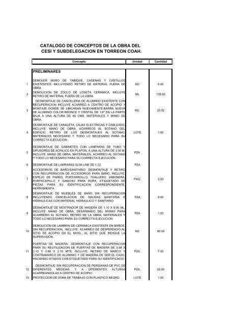
CATALOGO DE CONCEPTOS DE LA OBRA DELCESI Y SUBDELEGACION EN TORREON COAH.Concepto Unidad CantidadPRELIMINARES12345DEMOLER MURO DE TABIQUE, CADENAS Y CASTILLOSEXISTENTES; INCLUYENDO RETIRO DE MATERIAL FUERA DEOBRADEMOLICION DE ZOCLO DE LOSETA CERAMICA, INCLUYERETIRO DE MATERIAL FUERA DE LA OBRADESMONTAJE DE CANCELERIA DE ALUMINIO EXISTENTE CONRECUPERACION INCLUYE ACARREO A CENTRO DE ACOPIO YMONTAJE DONDE SE UBICARAN NUEVAMENTE,BARRA NUEVADE ALUMINIO COLOR BRONCE Y CRISTAL DE 1/4" EN LA PARTEBAJA A UNA ALTURA DE 80 CMS. MATERIALES Y MANO DEOBRA.DESMONTAJE DE CANALETA, CAJAS ELECTRICAS Y CABLEADO,INCLUYE: MANO DE OBRA, ACARREOS AL SOTANO DELEDIFICIO, RETIRO DE LOS DESMONTAJES AL SOTANO,MATERIALES NECESARIO Y TODO LO NECESARIO PARA SUCORRECTA EJECUCION.DESMONTAJE DE GABINETES CON LAMPARAS DE TUBO YDIFUSORES DE ACRILICO EN PLAFON, A UNA ALTURA DE 3.50 M.INCLUYE: MANO DE OBRA, MATERIALES, ACARREO AL SOTANOY TODO LO NECESARIO PARA SU CORRECTA EJECUCIÓN.M2 6.40ML 135.00M2. 20.92LOTE 1.00PZA.6 DESMONTAJE DE LAMPARAS SLIM LINE DE 1.22 PZA78ACCESORIOS DE BAÑO/SANITARIO: DESMONTAJE Y RETIROCON RECUPERACION DE ACCESORIOS PARA BAÑO, INCLUYE:ESPEJO DE PARED, PORTARROLLO, TOALLERO, JABONERA,PORTACEPILLO Y GANCHO PARA ROPA, ETIQUETADO DEPIEZAS PARA SU IDENTIFICACION CORRESPONDIENTE,HERRAMIENTADESMONTAJE DE MUEBLES DE BAÑO SIN RECUPERACIONINCLUYENDO CANCELACION DE SALIDAS SANITARIA EHIDRAULICAS CON MATERIAL HIDRAULICO Y SANITARIOPAQ. 2.00PZA 9.0091011DESMONTAJE DE MOSTRADOR DE MADERA DE 1.10 X 8.00 ML,INCLUYE: MANO DE OBRA, DESARMADO DEL MISMO PARAACARRERO AL SOTANO, RETIRO DE LA OBRA, MATERIALES YTODO LO NECESARIO PARA SU CORRECTA EJECUCIONDEMOLICIÓN DE LAMBRIN DE CERAMICA EXISTENTE EN BAÑOS.SIN RECUPERACION, INCLUYE: ACARREO DE DESPERDICIO ALSITIO DE ACOPIO EN EL NIVEL, AL SITIO QUE INDIQUE LASUPERVISIÓN.PUERTAS DE MADERA: DESMONTAJE CON RECUPERACIONPARA SU REUTILIZACION DE PUERTAS DE MADERA DE 0.98 X2.10 Y 0.88 X 2.10 MTS. INCLUYE: RETIRO DE MARCO YCONTRAMARCO DE ALUMINIO Y DE MADERA DE SER EL CASO,HACIENDO ATADOS CON ETIQUETADO PARA SU IDENTIFICACIOPZA 1.00M2 90.00PZA. 7.00DESMONTAJE SIN RECUPERACION DE PERSIANAS DE PVC DE12 DIFERENTES MEDIDAS Y A DIFERENTES ALTURAS PZA. 20.00ACARREANDOLAS A CENTRO DE ACOPIO13 PROTECCION DE ZONA DE TRABAJO CON PLASTICO NEGRO LOTE 1.00
ACABADOSSUMINISTRO Y APLICACION DE DE PINTURA DE ESMALTECOLOR BLANCO.SUMINISTRO Y APLICACIÓN DE PASTA ( CON COLOR GRISPERLA COMEX VINIMEX. REBAJADA AL 20 % CON COLORBLANCO) RAYADA EN MUROS, SOBRE MUESTRA APROBADAPOR LA SUPERVISION, INCLUYE: EMBOQUILLADOS DE ARISTASPREPARACION DE SUPERFICIE, APLICACIÓN DE SOTOFONDO,MANO DE OBRA Y MATERIALES.M2 18.00M2. 379.20MUROS: SUMINISTRO Y APLICACIÓN DE PINTURA VINILICAMARCA COMEX CALIDAD VINIMEX COLOR GRIS PERLA COMEXVINIMEX. REBAJADA AL 20 % CON COLOR BLANCOSOBREMUROS HASTA CUBRIR PERFECTAMENTE LA SUPERFICIE,INCLUYE: PROTECCION A PISOS, MUEBLES Y ENSERES DEOFICINA, MATERIAL, MANO DE OBRA, HERRAMIENTAS YEQUIPO.M2. 121.90PINTURA EN PUERTAS Y MARCOS EN COLOR GRIS CLARO. PZA 2.00SUMINISTRO Y COLOCACION DE PISO CERAMICO SOBRE PISOMARCA PORCELANITE, MODELO MAGNUM NEGRO DE 33 X 33CM, INCLUYE: MATERIALES, MANO DE OBRA Y HERRAMIENTA.SUMINISTRO Y COLOCACION DE ZOLCO CERÁMICO(PORCELANITE, MODELO MAGNUM NEGRO) DE 10 CM DEALTURA, INCLUYE: MATERIALES, MANO DE OBRA YHERRAMIENTA.SUMINISTRO Y COLOCACION DE PLAFON FALSO MARCAACUSTONE, MODELO GLACIAR DE 61X61 CM LINEA SOMBRA,INCLUYE: SUSPENSIÓN DONN O SIMILAR, ANGULOPERIMETRAL, MATERIALES, MANO DE OBRA Y HERRAMIENTA.M2 681.65ML 132.80M2 668.28MUEBLES Y ACCESORIOS PARA BAÑOSSUMINISTRO Y COLOCACION DE WC DE TANQUE BAJO, MARCAAMERICAN ESTANDAR, MODELO CADET, INCLUYENDO JUNTAPROHEL, PIJAS DE FIJACIÓN, HERRAJES DE TANQUE BAJO,AVALVULA DE SECCIONAMIENTO Y TUBO FLEXIBLE DEACOMETIDA DE AGUASUMINISTRO Y COLOCACION DE MINGITORIO MARCAAMERICAN ESTANDAR, MODELO ÑIAGARA, COLOR BLANCO,INCLUYENDO LLAVE DE CIERRE AUTOMATICASUMINISTRO Y COLOCACION DE LAVABO DE PEDESTAL, MARCALAMOSA MODELO CADET INCLUYENDO LLAVEECONOMIZADORA MARCA HELVEX PARA AGUA FRIA,YCESPOLY CUBRE TALADROSSUMINISTRO Y COLOCACION DE LAVABO DE VERTEDERO DEACERO INOXIDABLE, INCLUYENDO LLAVE PARA AGUA FRIA,CESPOL Y BASE.SUMINISTRO Y COLOCACION DE ESPEJO DE 0.90 X 1.00,INCLUYENDO SU MARCO DE ALUMINIOSUMINISTRO Y COLOCACON DE PORTA ROLLO MARCA JOFEL OSIMILARSUMINISTRO Y COLOCACION DE JABONAERA MARCA JOFEL OSIMILAR.SUMINISTRO Y COLOCACIÓN DE GANCHO CROMADO DESOBREPONER MARCA HELVEXSUMINISTRO Y COLOCACION DE SECADOR DE MANOS DEAPROXIMACIÓN MARCA HELVEX.PZA 7.00PZA 3.00PZA 3.00PZA 1.00PZA 3.00PZA 7.00PZA 3.00PZA 7.00PZA 2.00
SUMINISTRO E INSTALACIÓN DE MAMPARAS PARA BAÑO, DE1.80 M DE ALTURA Y SEPARADAS DEL PISO 0.30 M, FABRICADASDE LÁMINA MULTIPANEL, ENMARCADAS CON PERFILI DEALUMINIO.JUEGO 1.00CARPINTERIASIMINISTRO E INSTALACION DE PUERTAS DEINTERCOMUNICACION, CON TAMBOR DE PINO Y TRIPLAY DE 6MM. ACABADAS CON FORRO DE WILSON DOOR COLOR GRIS,INCLUYE CHAPA MARCA YALE, 4 BISAGRAS DE 3" DE ALUMINIOY MARCO DE MADERA ACABADO EN LACA, DE 0.90 X 2.35 M.PZA 2.00CANCELERIACANCELERIA DE ALUMINIO LINEA 3 " CONACABADO ANODIZADO NATURAL Y CRISTAL DE 6mm.; TODA LA CANCELERIA LLEVARA UN PERFILHORIZONTAL A 90 CM SOBRE EL NIVEL DEL PISOTERMINADO, MODULANDO LA CANCELERIA A 1.20M ( HORIZONTALMENTE)RECORTE Y AJUSTE DE PUERTAS DE ACCESO AL LOCAL,INSTALANDO CIERRAPUERTAS HIDRÁULICOS EN CADA PUERTA.RECORTE Y AJUSTE DEL CANCEL EXTERIOR PARA ELSUMINISTRO E INSTALACIÓN DE PUERTA DE ACCESO A MEDIOSALTYERNOS.SUMINISTRO E INSTALACION DE CANCEL DE ACCESO A LASUBDELEGACION, FORMADO POR UN FIJO, DOS PUERTAS DE0.90 M. CON CIERRAPUERTA HIDRÁULICO, Y ANTEPECHO, LAMEDIDA TOTAL DEL CANCEL ES DE 2.00 X 2.40SUMINISTRO E INSTALACION DE CANCEL EN ESCUADRA PARAMEDIOS ALTERNOS, DE 3.80 - 7.00 X 2.40 M. DE ALTURA,INCLUYE UNA PUERTA DE 0.90 M.SUMINISTRO E INSTALACION DE CANCEL EN " C" PARA DIVIDIRLA SUBDELEGACION Y EL CECI, DE 7.00 - 19.00 - 2.60 X 2.40 M.DE ALTURA, INCLUYE 3 PUERTAS DE 0.90 M.SUMINISTRO E INSTALACION DE CANCEL EN ESCUADRA PARASALA DE JUNTAS, DE 8.00 - 4.50 X 2.40 M. DE ALTURA, INCLUYEUNA PUERTA DE 0.90 M.SUMINISTRO E INSTALACION DE CANCEL EN ESCUADRA PARAGERENTE DEL CESI, DE 3.20 - 4.50 X 2.40 M. DE ALTURA,INCLUYE UNA PUERTA DE 0.90 M.SUMINISTRO E INSTALACION DE CANCEL EN ESCUADRA PARASUBDELEGADO, DE 4.00 - 5.00 X 2.40 M. DE ALTURA, INCLUYEUNA PUERTA DE 0.90 M.SUMINISTRO Y COLOCACION DE TOPE PARA PUERTA A PISODE LATON CROMADO. INCLUYE: MATERIALES, MANO DE OBRAY HERRAMIENTA.PZA 1.00PZA 1.00PZA 1.00PZA 1.00PZA 1.00PZA 1.00PZA 1.00M2 1.00PZA. 11.00INSTALACION ELECTRICAACOMETIDA PRINCIPAL
SUMINISTRO E INSTALACION DE UN CIRCUITO ALIMENTADORDE ENTRADA: DEL TAB-01 A LA ENTRADA DEL UPS DE 15 KVA.EL CIRCUITO CONSTA DE 3 FASES, CADA FASE CON 1H-4, UNNEUTRO 1H-1/0 Y UNA TIERRA 1H-1/0, CON UNA LONGITUDAPROXIMADA DE 8 MTS, CONTENIDOS EN DUCTO CUADRADODE 20 POR 20 CM Y TUBO CONDUIT FLEXIBLE DE 2 PULGADAS,PROTEGIDOS POR UN INTERRUPTOR TIPO FAL DE 3 POLOS 60AMPERES EN EL TAB-01 REMATADO EN LA ENTRADA DEL UPSPASANDO E INTERCONECTANDOSE EN EL GABINETE DEBYPASS. ALIMENTADOR DE SALIDA: DE LA SALIDA DEL UPS ALAS BARRAS DEL TAB-02. EL CIRCUITO CONSTA DE 3 FASES,CADA FASE CON 1H-4, UN NEUTRO 1H-2 Y UNA TIERRA 1H-1/0,CON UNA LONGITUD APROXIMADA DE 8 MTS, CONTENIDOS ENDUCTO CUADRADO DE 20 POR 20 CM Y TUBO CONDUITFLEXIBLE DE 2 PULGADAS, PASANDO E INTERCONECTANDOSEEN EL GABINETE DE BYPASS Y EN EL FAL DE 3 POLOS 50AMPERES (VER ESQ. DE INSTALACION DEL UPS), INCLUYE:MANO DE OBRA, MATERIALES Y TODO LO NECESARIO PARA SUCORRECTA INSTALACION. CIRC. 1CIRCUITOS DERIVADOS DEL TABLERO-02CONTACTOS BAJO UPS DE 15 KVASUMINISTRO E INSTALACION DE 13 CIRCUITOS DERIVADOS DELTAB-02 CON CABLE CAL. 12 THW TRES HILOS, UNA FASE UNNEUTRO Y UNA TIERRA (DE ACUERDO A ESPECIFICACION DECOLORES FASE), CON UNA LONGITUD PROMEDIO DE 45 MTS,CONTENIDOS EN TUBO CONDUIT DE PARED DELGADA DE 2PULGADAS EN HORIZONTAL PRINCIPAL EN TECHO Y ENCANALETA DE ALUMINIO MARCA THORSMAN MOD. INKA 100 ENHORIZONTAL Y BAJADAS EN PARED, MENCIONADASPOSTERIORMENTE Y PROTEGIDOS CON UN ELEMENTOTERMOMAGNETICO QOB DE UN POLO 15 AMPERES EN ELTABLERO 02, REMATADOS EN LOS LUGARES INDICADOS EN ELPLANO EN CONTACTOS POLARIZADOS DE TIERRA AISLADACOLOR NARANJA CON TAPA COLOR NARANJAPROPORCIONADOS POR EL INSTALADOR DE LOS MUEBLES. ENCASO DE SER NECESARIO LES SOLICITAMOS PROPOCIONENLOS CONTACTOS ADICIONALES Y PLACAS ADICIONALES.DEBERÁN DE APEGARSE DE FORMA ESTRICTA AL DIAGRAMAUNIFILAR ENTREGADO. INCLUYE: MATERIALES, MANO DE OBRAY TODO LO NECESARIO PARA SU CORRECTA INSTALACIÓN. CIRC. 13CIRC. ALIMENTADOR ENTRADA Y SALIDA PARAREG. DE 15 KVA
SUMINISTRO E INSTALACION DE UN CIRCUITOALIMENTADOR DE ENTRADA: DEL TAB-01 A LAENTRADA DEL REGULADOR DE 15 KVA. ELCIRCUITO CONSTA DE 3 FASES, CADA FASE CON1H-4, UN NEUTRO 1H-4 Y UNA TIERRA 1H-6, CONUNA LONGITUD APROXIMADA DE 8 MTS,CONTENIDOS EN DUCTO CUADRADO DE 20 POR 20CM (MENCIONADO POSTERIORMENTE)Y TUBOCONDUIT FLEXIBLE DE 2 PULGADAS, PROTEGIDOSPOR UN INTERRUPTOR TIPO FAL DE 3 POLOS 60AMPERES EN EL TAB-01 REMATADO EN LAENTRADA DEL REGULADOR PASANDO EINTERCONECTANDOSE EN EL GABINETE DEBYPASS (INTERRUPTOR DE SEGURIDAD DE 3POLOS DOBLE TIRO). ALIMENTADOR DE SALIDA:DEL LA SALIDA DEL REGULADOR A LAS BARRASDEL TAB-03 (NQOD-12). EL CIRCUITO CONSTA DE 3FASES, CADA FASE CON 1H-4, UN NEUTRO 1H-4 YUNA TIERRA 1H-6, CON UNA LONGITUDAPROXIMADA DE 8 MTS, CONTENIDOS EN DUCTOCUADRADO DE 20 POR 20 CM Y TUBO CONDUITFLEXIBLE DE 2 PULGADAS, PASANDO EINTERCONECTANDOSE EN EL GABINETE DEBYPASS (VER ESQ. DE INSTALACION DELREGULADOR), INCLUYE: MANO DE OBRA,MATERIALES Y TODO LO NECESARIO PARA SUCORRECTA INSTALACION. CIRC. 1CIRC. DERIVADOS DEL TAB-03 CONTACTOS BAJOREGULADORSUMINISTRO E INSTALACION DE 4 CIRCUITOS DERIVADOS DELTAB-03 (NQOD-12) CON CABLE CAL. 12 THW TRES HILOS, UNAFASE UN NEUTRO Y UNA TIERRA (DE ACUERDO AESPECIFICACION DE COLORES FASE), CON UNA LONGITUDPROMEDIO DE 45 MTS, CONTENIDOS EN TUBO CONDUIT DEPARED DELGADA DE 2 PULGADAS EN HORIZONTAL PRINCIPALEN TECHO Y EN CANALETA DE ALUMINIO MARCA THORSMANMOD. INKA 100 EN HORIZONTAL Y BAJADAS EN PARED. INKA100, MENCIONADA POSTERIORMENTE, PROTEGIDOS CON UNELEMENTO TERMOMAGNETICO QOB DE UN POLO 20 AMPERESEN EL TAB-03, REMATADOS EN LOS LUGARES INDICADOS EN ELPLANO EN CONTACTOS POLARIZADOS DE TIERRA AISLADACOLOR NARANJA CON TAPA COLOR NEGRO PROPORCIONADOSPOR EL INSTALADOR DE LOS MUEBLES. EN CASO DE SERNECESARIO LES SOLICITAMOS PROPOCIONEN LOSCONTACTOS ADICIONALES Y PLACAS ADICIONALES. DEBERÁNDE APEGARSE DE FORMA ESTRICTA AL DIAGRAMA UNIFILARENTREGADO. INCLUYE: MATERIALES, MANO DE OBRA Y TODOLO NECESARIO PARA SU CORRECTA INSTALACIÓN. CIRC. 4CIRC. ALIMEN. PARA TAB-04 DE CONTACTOSNORMALES Y ESP.
SUMINISTRO E INSTALACION DE UN CIRCUITO ALIMENTADORDE ENTRADA DEL TABLERO-01 AL TABLERO-04, EL CIRCUITOCONSTA DE TRES FASES C/UNA CON 1H-4, UN NEUTRO 1H-4 YUNA TIERRA CON CABLE 1H-4, CON UNA LONGITUD PROMEDIODE 5 MTS, CONTENIDOS EN EL DUCTO CUADRADO DE 20 POR20 CM (MENCIONADO POSTERIORMENTE), PROTEGIDO POR UNINTERRUPTOR TERMOMAGNETICO TIPO FAL DE TRES POLOS 70AMPERES EN EL TABLERO-01 Y REMATADO EN LAS BARRASDEL TABLERO-04, INCLUYE: MATERIALES, MANO DE OBRA YTODO LO NECESARIO PARA SU CORRECTA INSTALACIÓN. CIRC. 1CIRCUITOS DERIVADOS DE CONTACTOSNORMALESSUMINISTRO E INSTALACION DE 5 CIRCUITOS DERIVADOS DELTABLERO-04 CON CABLE CAL. 12 THW TRES HILOS, UNA FASEUN NEUTRO Y UNA TIERRA (DE ACUERDO A ESPECIFICACIONDE COLORES FASE), CON UNA LONGITUD PROMEDIO DE 45MTS, CONTENIDOS EN TUBO CONDUIT DE PARED DELGADA DE2 PULGADAS EN HORIZONTAL PRINCIPAL EN TECHO Y ENCANALETA DE ALUMINIO MARCA THORSMAN MOD. INKA 100 ENHORIZONTAL Y BAJADAS EN PARED, MENCIONADAPOSTERIORMENTE, PROTEGIDOS CON UN ELEMENTOTERMOMAGNETICO QOB DE UN POLO 20 AMPERES EN EL TAB-04, REMATADOS EN LOS LUGARES INDICADOS EN EL PLANO ENCONTACTOS POLARIZADOS NORMALES COLOR BEIGE CONTAPA COLOR BEIGE PROPORCIONADOS POR EL INSTALADORDE LOS MUEBLES. EN CASO DE SER NECESARIO LESSOLICITAMOS PROPOCIONEN LOS CONTACTOS ADICIONALES YPLACAS ADICIONALES. DEBERÁN DE APEGARSE DE FORMAESTRICTA AL DIAGRAMA UNIFILAR ENTREGADO. INCLUYE:MATERIALES, MANO DE OBRA Y TODO LO NECESARIO PARA SUCORRECTA INSTALACIÓN. CIRC. 5CIRCUITOS DERIVADOS DE CONTACTOSESPECIALESSUMINISTRO E INSTALACION DE 4 CIRCUITOS DERIVADOS DELTABLERO-04 CON CABLE CAL. 12 THW TRES HILOS, UNA FASEUN NEUTRO Y UNA TIERRA (DE ACUERDO A ESPECIFICACIONDE COLORES FASE), CON UNA LONGITUD PROMEDIO DE 45MTS, CONTENIDOS EN TUBO CONDUIT DE PARED DELGADA DE2 PULGADAS EN HORIZONTAL PRINCIPAL EN TECHO Y ENCANALETA DE ALUMINIO MARCA THORSMAN MOD. INKA 100 ENHORIZONTAL Y BAJADAS EN PARED,PROTEGIDOS CON UNELEMENTO TERMOMAGNETICO QOB DE UN POLO 20 AMPERESEN EL TAB-04, REMATADOS EN LOS LUGARES INDICADOS EN ELPLANO EN CONTACTOS POLARIZADOS NORMALES COLORBLANCO CON TAPA COLOR BLANCO. DEBERÁN DE APEGARSEDE FORMA ESTRICTA AL DIAGRAMA UNIFILAR ENTREGADO.INCLUYE: MATERIALES, MANO DE OBRA Y TODO LO NECESARIOPARA SU CORRECTA INSTALACIÓN. CIRC. 4CIRCUITO ALIMENTADOR PARA TABLERO 05 PARAALUMBRADO
SUMINISTRO E INSTALACION DE UN CIRCUITO ALIMENTADORDE ENTRADA DEL TABLERO-01 AL TABLERO-05, EL CIRCUITOCONSTA DE TRES FASES C/UNA CON 1H-1/0, UN NEUTRO 1H-1/0Y UNA TIERRA CON CABLE 1H-1/0, CON UNA LONGITUDPROMEDIO DE 5 MTS, CONTENIDOS EN EL DUCTO CUADRADODE 20 POR 20 CM (MENCIONADO POSTERIORMENTE),PROTEGIDO POR UN INTERRUPTOR TERMOMAGNETICO TIPOFAL DE TRES POLOS 100 AMPERES EN EL TABLERO-01 YREMATADO EN LAS BARRAS DEL TABLERO-05, INCLUYE:MATERIALES, MANO DE OBRA Y TODO LO NECESARIO PARA SUCORRECTA INSTALACIÓN. CIRC. 1CIRCUITOS DERIVADOS DE ALUMBRADOSUMINISTRO E INSTALACION DE 10 CIRCUITOS DERIVADOS DELTABLERO-05 A LAS LAMPARAS DEL SISTEMA DE ALUMBRADO,CON CABLE CAL. 12 THW TRES HILOS, UNA FASE UN NEUTRO YUNA TIERRA (DE ACUERDO A ESPECIFICACION DE COLORESPOR FASE), CON UNA LONGITUD APROXIMADA DE 45 MTS,CONTENIDOS EN TUBO CONDUIT DE PARED DELGADA DE 2PULGADAS EN LA TRAYECTORIA PRINCIPAL Y EN LASECUNDARIA EN TUBO DE CONDUIT P.D. DE 1 PULGADA(MENCIONADA POSTERIORMENTE), PROTEGIDOS CON UNELEMENTO TERMOMAGNETICO QOB DE UN POLO 20 AMPERESEN EL TABLERO 05 Y REMATADO EN LAS LAMPARASINDICADADAS EN EL PLANO; NOTA: EN LOS LUGARES ENDONDE SE TRABAJE DE FORMA INDIVIDUAL O USO EXCLUSIVOSE DEBERA DE INSTALAR DE FORMA ADICIONAL UN APAGADORA PARED ESTOS DE COMUN ACUERDO CON EL PERSONAL DESUPERVISION DE OBRA DEL INFONAVIT, INCLUYE:MATERIALES, MANO DE OBRA Y HERRAMIENTA Y TODO LONECESARIO PARA SU CORRECTA INSTALACIÓN. CIRC. 10LAMPARASSUMINISTRO E INSTALACION DE 119 LAMPARAS TIPO TUBO T-8DE 32 WATTS TIPO CURVALUM, CON BALASTRA ELECTRONICA,CON GABINETE DE 0.61 X 0.61 M, CON DIFUSOR DE ALUMINIO A16 CUADROS EN PLAFON. INCLUYE: SOPORTES PARA LOSTUBOS MARCA LEVINGTON T-8, MANO DE OBRA, MATERIALES YTODO LO NECESARIO PARA SU CORRECTA INSTALACION. LAMP. 119CIRCUITO ALIMENTADOR PARA TABLERO 06AIRES ACONDICONADOSSUMINISTRO E INSTALACION DE UN CIRCUITO ALIMENTADORDE ENTRADA DE LAS BARRAS DEL TABLERO-01 AL TABLERO-06, EL CIRCUITO CONSTA DE TRES FASES CA/UNA CON 1H-250MCM , UN NEUTRO 1H-250 MCM Y UNA TIERRA CON CABLE 1H-1/0, CON UNA LONGITUD PROMEDIO DE 6 MTS, CONTENIDOS ENEL DUCTO CUADRADO DE 20 POR 20 CM (MENCIONADOPOSTERIORMENTE), PROTEGIDO POR UN INTERRUPTORTERMOMAGNETICO TIPO KAL CON GABINETE DE SOBREPONERDE TRES POLOS 200 AMPERES A SU VES REMATADO EN ELTABLERO-01 Y REMATADO EN LAS BARRAS DEL TABLERO-06,INCLUYE: MATERIALES, MANO DE OBRA Y TODO LO NECESARIOPARA SU CORRECTA INSTALACIÓN. CIRC. 1CIRCUITOS DERIVADOS DEL TABERO 06 AIRESACONDICIONADOS
SUMINISTRO E INSTALACION DE DIEZ Y SEIS CIRCUITOSDERIVADOS DEL TABLERO 06, DIEZ Y SEIS CON CABLE CAL. 8THW CONSTA DE 4 HILOS 2 FASES UN NEUTRO Y TIERRA (DEACUERDO A ESPECIFICACION DE COLORES POR FASE), CONUNA LONGITUD PROMEDIO DE 50 MTS, CONTENIDOS EN TUBOCONDUIT DE PARED DELGADA DE 2 PULGADAS (MENCIONADOPOSTERIORMENTE) Y PROTEGIDOS LOS 16 PRIMEROPS CONUN ELEMENTO TERMOMAGNETICO DE DOS POLOS 40AMPERES, LOS SEGUNDOS CON UN ELEMENTOTERMOMAGNETICO DE TRES POLOS 50 AMPERES Y ULTIMOCON UN ELEMENTO TERMOMAGNETICO DE UN POLO 20AMPERES, REMATADOS EN LOS LUGARES INDICADOS EN ELPLANO EN CONTACTOS POLARIZADOS DE ACUERDO AESPECIFICACIONES DEL FABRICANTE DE LOS SISTEMAS DEAIRE ACONDICIONADO. INCLUYE: MATERIALES, MANO DEOBRA, HERRAMIENTA Y TODO LO NECESARIO PARA SUCORRECTA INSTALACIÓN. CIRC. 16TIERRA FISICASUMINISTRO E INSTALACION DE UN SISTEMA DE TIERRA FÍSICAEN DELTA. EL SISTEMA CONSTA DE TRES VARILLASCOOPERWELD CON PROTOCOLO (SI SE INSTALA DE OTRAMARCA O SIN PROTOCOLO NO SE ACEPTARAN LOS TRABAJOSCORRESPONDIENTES, SOLO QUE EXISTA UN PREVIO ACUERDOCON EL PERSONAL DE SUPERVISIÓN DEL INSTITUTO). UNABARRA DE COBRE DE 1/4 DE PULG, DE ESPESOR DE 5X20 CM,LA INTERCONEXION ENTRE LA BARRA Y LA VARILLA SE DEBERADE LLEVAR A CABO CON CABLE THW DE 1/0 CON FORRO ENCOLOR VERDE SOLDADA CON CARGA EXPLOCIONADA A LAVARILLA.SE INDICARA EL ÁREA EN DONDE SE INSTALARA EL SISTEMA.LA INTERCONEXION ENTRE EL CABLE Y LA BARRA CONTERMINAL PONCHADA MECANICAMENTE, COMO ADITIVO SEADICIONARA UN COSTAL DE GEM POR VARILLA SE DEBERÁNDE SEGUIR LAS INSTRUCCIONES DE ACUERDO A LAESPECIFICACION ANEXA, DE LA BARRA DE TIERRAS DEBERANDE SALIR LAS CONEXIONES DE TIERRA A TODOS LOS CENTROSDE CARGA Y AL RACK DE COMUNICACIONES CON CABLE CAL 6THW CON FORRO EN COLOR VERDE, INCLUYE: MATERIALES,MANO DE OBRA Y HERRAMIENTA Y TODO LO NECESARIO PARASU CORRECTA INSTALACIÓN. SISTEMA 1DUCTOS Y CANALIZACIONSUMINISTRO E INSTALACION DE DE TUBO CONDUIT DE PAREDGRUESA DE 3 1/2 PULGADAS, PARA CONTENCION DELCIRCUITO ALIMENTADOR PRINCIPAL EN EXTERIOR, INCLUYE:MATERIALES, MANO DE OBRA Y HERRAMIENTA Y TODO LONECESARIO PARA SU CORRECTA INSTALACIÓN. MTS. 18
SUMINISTRO E INSTALACION DE DE TUBO CONDUIT DE PAREDDELGADA DE 2 PULGADAS (TRAYECTORIAS PRINCIPALES) PARACONTENCION DE LOS CIRCUITOS DE ALIMENTACION PARACONTACTOS DE UPS, REGULADOS, AIRE ACONDICINADO,NORMALES Y ALUMBRADO DE ACUERDO A LA TRAYECTORIAPROPUESTA EN EL PLANO DE INSTALACIONES, INCLUYE:MATERIALES, MANO DE OBRA Y HERRAMIENTA Y TODO LONECESARIO PARA SU CORRECTA INSTALACIÓN. MTS. 120SUMINISTRO E INSTALACION DE UNA LINEA DE TUBO CONDUITDE PARED DELGADA DE 1 PULGADA (TRAYECTORIASSECUNDARIAS) PARA CONTENCION DE LAS LINEAS DECONTROL DE ALUMBRADO Y BAJADAS DE CONTACTOS DEACUERDO ALA TRAYECTORIA PROPUESTA EN EL PLANO DEINSTALACIONES,EMPOTRADO EN LA PARED EN LOS LUGARESINDICADOS POR EL SUPERVISOR DE OBRA INCLUYE:MATERIALES, MANO DE OBRA, RANURADO, HERRAMIENTA YTODO LO NECESARIO PARA SU CORRECTA INSTALACIÓN. MTS. 90SUMINISTRO E INSTALACION DE UNA LINEA DE DUCTOCUADRADO DE 20X20 CM A 1.40 METROS DEL NIVEL DEL PISODENTRO DEL CUARTO DE EQUIPOS EN DONDE SEINTERCONECTARAN TODOS LOS CENTROS DE CARGAESPECIFICADOS , LA TUBERIA ELÉCTRICA Y LAS CONEXIONESDE ENTRADA Y SALIDA DE LOS UPS Y DEL REGULADOR,INCLUYE: MATERIALES, MANO DE OBRA Y HERRAMIENTA YTODO LO NECESARIO PARA SU CORRECTA INSTALACIÓN. MTS. 8SUMINISTRO E INSTALACION DE CANALETA DE ALUMINO INCA100 MARCA THORSMAN A INSTALARSE COMO CANALIZACIONPERIMETRAL Y DUCTO DE BAJADA EN DONDE SEA NECESARIO,INCLUYE: MATERIALES, MANO DE OBRA Y HERRAMIENTA YTODO LO NECESARIO PARA SU CORRECTA INSTALACIÓN. MTS. 70AIRE ACONDICIONADO1.00 Suministro y colocación <strong>de</strong> equipo <strong>de</strong> aire acondicionado, marca Traneo similar, con capacidad <strong>de</strong> 18,000 BTU/HORA, con una unida<strong>de</strong>vaporadora para instalarse en el techo (interior) y otracon<strong>de</strong>nsadora, para instalarse en el exterior (azotea), interconectadasentre ellas atravez <strong>de</strong> 9.00 m.l. tubo <strong>de</strong> cobre tipo "L" <strong>de</strong> 1/2" <strong>de</strong>diametro y 9 m.l. tubo <strong>de</strong> cobre <strong>de</strong> 1/4", 3 codos <strong>de</strong> 90°x1/2" y 3 codos<strong>de</strong> 90°x 1/4", 2 conectores <strong>de</strong> 1/2" y 2 conectores <strong>de</strong> 1/4", 9.00 m.l.<strong>de</strong>aislamiento tipo elastomero preformado para tubo <strong>de</strong> 1/2"<strong>de</strong> diametroy 3/4" <strong>de</strong> espesor, valvula <strong>de</strong> termoexpansion para 1.5 T.R., 1 bulbosensor, 1 valvula <strong>de</strong> 2 vias, indicador <strong>de</strong> liquido, filtro <strong>de</strong>shidratadorpara 1.5 T.R., 2 kgrs. <strong>de</strong> gas refrigerante freon 22, soldadura,oxiacetileno, <strong>de</strong>berá <strong>de</strong> incluir todo lo necesario para su correctainstalación, incluye pruebas y ajustes EQUIPO N° 1PZA. 1
1.01 Suministro y colocación <strong>de</strong> equipo <strong>de</strong> aire acondicionado, marca Traneo similar, con capacidad <strong>de</strong> 24,000 BTU/HORA, con una unida<strong>de</strong>vaporadora para instalarse en el techo (interior) y otracon<strong>de</strong>nsadora, para instalarse en el exterior (azotea), interconectadasentre ellas atravez <strong>de</strong> 5.00 m.l. tubo <strong>de</strong> cobre tipo "L" <strong>de</strong> 5/8" <strong>de</strong>diametro y 5.00 m.l. tubo <strong>de</strong> cobre <strong>de</strong> 1/4", 3 codos <strong>de</strong> 90°x5/8" y 3codos <strong>de</strong> 90°x 1/4", 2 conectores <strong>de</strong> 5/8" y 2 conectores <strong>de</strong> 1/4", 5.00m.l.<strong>de</strong> aislamiento tipo elastomero preformado para tubo <strong>de</strong> 5/8"<strong>de</strong>diametro y 3/4" <strong>de</strong> espesor, valvula <strong>de</strong> termoexpansion para 2 T.R., 1bulbo sensor, 1 valvula <strong>de</strong> 2 vias, indicador <strong>de</strong> liquido, filtro<strong>de</strong>shidratador para 2 T.R., 3 kgrs. <strong>de</strong> gas refrigerante freon 22,soldadura, oxiacetileno, <strong>de</strong>berá <strong>de</strong> incluir todo lo necesario para sucorrecta instalación y soporteria, incluye pruebas y ajustes EQUIPO N°2PZA. 11.02 Suministro y colocación <strong>de</strong> equipo <strong>de</strong> aire acondicionado, marca Traneo similar, con capacidad <strong>de</strong> 24,000 BTU/HORA, con una unida<strong>de</strong>vaporadora para instalarse en el techo (interior) y otracon<strong>de</strong>nsadora, para instalarse en el exterior (azotea), interconectadasentre ellas atravez <strong>de</strong> 12.00 m.l. tubo <strong>de</strong> cobre tipo "L" <strong>de</strong> 5/8" <strong>de</strong>diametro y 12.00 m.l. tubo <strong>de</strong> cobre <strong>de</strong> 174", 3 codos <strong>de</strong> 90°x5/8" y 3codos <strong>de</strong> 90°x 1/4", 2 conectores <strong>de</strong> 5/8" y 2 conectores <strong>de</strong> 5/8", 12.00m.l.<strong>de</strong> aislamiento tipo elastomero preformado para tubo <strong>de</strong> 5/8"<strong>de</strong>diametro y 3/4" <strong>de</strong> espesor, valvula <strong>de</strong> termoexpansion para 2 T.R., 1bulbo sensor, 1 valvula <strong>de</strong> 2 vias, indicador <strong>de</strong> liquido, filtro<strong>de</strong>shidratador para 2 T.R., 3 kgrs. <strong>de</strong> gas refrigerante freon 22,soldadura, oxiacetileno, <strong>de</strong>berá <strong>de</strong> incluir todo lo necesario para sucorrecta instalación y soporteria, incluye pruebas y ajustes EQUIPO N°3PZA. 11.03 Suministro y colocación <strong>de</strong> equipo <strong>de</strong> aire acondicionado, marca Traneo similar, con capacidad <strong>de</strong> 24,000 BTU/HORA, con una unida<strong>de</strong>vaporadora para instalarse en el techo (interior) y otracon<strong>de</strong>nsadora, para instalarse en el exterior (azotea), interconectadasentre ellas atravez <strong>de</strong> 5.00 m.l. tubo <strong>de</strong> cobre tipo "L" <strong>de</strong> 5/8" <strong>de</strong>diametro y 5.00 m.l. tubo <strong>de</strong> cobre <strong>de</strong> 1/4", 3 codos <strong>de</strong> 90°x5/8" y 3codos <strong>de</strong> 90°x 1/4", 2 conectores <strong>de</strong> 5/8" y 2 conectores <strong>de</strong> 1/4", 5.00m.l.<strong>de</strong> aislamiento tipo elastomero preformado para tubo <strong>de</strong> 5/8"<strong>de</strong>diametro y 3/4" <strong>de</strong> espesor, valvula <strong>de</strong> termoexpansion para 2 T.R., 1bulbo sensor, 1 valvula <strong>de</strong> 2 vias, indicador <strong>de</strong> liquido, filtro<strong>de</strong>shidratador para 2 T.R., 3 kgrs. <strong>de</strong> gas refrigerante freon 22,soldadura, oxiacetileno, <strong>de</strong>berá <strong>de</strong> incluir todo lo necesario para sucorrecta instalación y soporteria, incluye pruebas y ajustes EQUIPO N°4PZA. 1
1.04 Suministro y colocación <strong>de</strong> equipo <strong>de</strong> aire acondicionado, marca Traneo similar, con capacidad <strong>de</strong> 24,000 BTU/HORA, con una unida<strong>de</strong>vaporadora para instalarse en el techo (interior) y otracon<strong>de</strong>nsadora, para instalarse en el exterior (azotea), interconectadasentre ellas atravez <strong>de</strong> 5.00 m.l. tubo <strong>de</strong> cobre tipo "L" <strong>de</strong> 5/8" <strong>de</strong>diametro y 5.00 m.l. tubo <strong>de</strong> cobre <strong>de</strong> 1/4", 3 codos <strong>de</strong> 90°x5/8" y 3codos <strong>de</strong> 90°x 1/4", 2 conectores <strong>de</strong> 5/8" y 2 conectores <strong>de</strong> 1/4", 5.00m.l.<strong>de</strong> aislamiento tipo elastomero preformado para tubo <strong>de</strong> 5/8"<strong>de</strong>diametro y 3/4" <strong>de</strong> espesor, valvula <strong>de</strong> termoexpansion para 2 T.R., 1bulbo sensor, 1 valvula <strong>de</strong> 2 vias, indicador <strong>de</strong> liquido, filtro<strong>de</strong>shidratador para 2 T.R., 3 kgrs. <strong>de</strong> gas refrigerante freon 22,soldadura, oxiacetileno, <strong>de</strong>berá <strong>de</strong> incluir todo lo necesario para sucorrecta instalación y soporteria, incluye pruebas y ajustes EQUIPO N°5PZA. 11.05 Suministro y colocación <strong>de</strong> equipo <strong>de</strong> aire acondicionado, marca Traneo similar, con capacidad <strong>de</strong> 12,000 BTU/HORA, con una unida<strong>de</strong>vaporadora para instalarse en el techo (interior) y otracon<strong>de</strong>nsadora, para instalarse en el exterior (azotea), interconectadasentre ellas atravez <strong>de</strong> 11.00 m.l. tubo <strong>de</strong> cobre tipo "L" <strong>de</strong> 1/2" <strong>de</strong>diametro y 11 m.l. tubo <strong>de</strong> cobre <strong>de</strong> 1/4", 6 codos <strong>de</strong> 90°x1/2 y 6 codos<strong>de</strong> 90°x 1/4", 2 conectores <strong>de</strong> 1/2" y 2 conectores <strong>de</strong> 1/4", 11.00 m.l.<strong>de</strong>aislamiento tipo elastomero preformado para tubo <strong>de</strong> 1/2"<strong>de</strong> diametroy 3/4" <strong>de</strong> espesor, valvula <strong>de</strong> termoexpansion para 1.0 T.R., 1 bulbosensor, 1 valvula <strong>de</strong> 2 vias, indicador <strong>de</strong> liquido, filtro <strong>de</strong>shidratadorpara 1.0 T.R., 2 kgrs. <strong>de</strong> gas refrigerante freon 22, soldadura,oxiacetileno, <strong>de</strong>berá <strong>de</strong> incluir todo lo necesario para su correctainstalación y soporteria, incluye pruebas y ajustes EQUIPO N° 6PZA. 11.06 Suministro y colocación <strong>de</strong> equipo <strong>de</strong> aire acondicionado, marca Traneo similar, con capacidad <strong>de</strong> 18,000 BTU/HORA, con una unida<strong>de</strong>vaporadora para instalarse en el techo (interior) y otracon<strong>de</strong>nsadora, para instalarse en el exterior (azotea), interconectadasentre ellas atravez <strong>de</strong> 5.00 m.l. tubo <strong>de</strong> cobre tipo "L" <strong>de</strong> 1/2" <strong>de</strong>diametro y 5.00 m.l. tubo <strong>de</strong> cobre <strong>de</strong> 1/4", 3 codos <strong>de</strong> 90°x1/2" y 3codos <strong>de</strong> 90°x 1/4", 2 conectores <strong>de</strong> 1/2" y 2 conectores <strong>de</strong> 1/4", 9.00m.l.<strong>de</strong> aislamiento tipo elastomero preformado para tubo <strong>de</strong> 1/2"<strong>de</strong>diametro y 3/4" <strong>de</strong> espesor, valvula <strong>de</strong> termoexpansion para 1.5 T.R.,1 bulbo sensor, 1 valvula <strong>de</strong> 2 vias, indicador <strong>de</strong> liquido, filtro<strong>de</strong>shidratador para 1.5 T.R., 2 kgrs. <strong>de</strong> gas refrigerante freon 22,soldadura, oxiacetileno, <strong>de</strong>berá <strong>de</strong> incluir todo lo necesario para sucorrecta instalación, incluye pruebas y ajustes EQUIPO N° 7PZA. 1
1.07 Suministro y colocación <strong>de</strong> equipo <strong>de</strong> aire acondicionado, marca Traneo similar, con capacidad <strong>de</strong> 24,000 BTU/HORA, con una unida<strong>de</strong>vaporadora para instalarse en el techo (interior) y otracon<strong>de</strong>nsadora, para instalarse en el exterior (azotea), interconectadasentre ellas atravez <strong>de</strong> 11.00 m.l. tubo <strong>de</strong> cobre tipo "L" <strong>de</strong> 5/8" <strong>de</strong>diametro y 11.00 m.l. tubo <strong>de</strong> cobre <strong>de</strong> 1/4", 3 codos <strong>de</strong> 90°x5/8" y 3codos <strong>de</strong> 90°x 1/4", 2 conectores <strong>de</strong> 5/8" y 2 conectores <strong>de</strong> 1/4", 11.00m.l.<strong>de</strong> aislamiento tipo elastomero preformado para tubo <strong>de</strong> 5/8"<strong>de</strong>diametro y 3/4" <strong>de</strong> espesor, valvula <strong>de</strong> termoexpansion para 2 T.R., 1bulbo sensor, 1 valvula <strong>de</strong> 2 vias, indicador <strong>de</strong> liquido, filtro<strong>de</strong>shidratador para 2 T.R., 3 kgrs. <strong>de</strong> gas refrigerante freon 22,soldadura, oxiacetileno, <strong>de</strong>berá <strong>de</strong> incluir todo lo necesario para sucorrecta instalación y soporteria, incluye pruebas y ajustes EQUIPO N°8PZA. 11.08 Suministro y colocación <strong>de</strong> equipo <strong>de</strong> aire acondicionado, marca Traneo similar, con capacidad <strong>de</strong> 18,000 BTU/HORA, con una unida<strong>de</strong>vaporadora para instalarse en el techo (interior) y otracon<strong>de</strong>nsadora, para instalarse en el exterior (azotea), interconectadasentre ellas atravez <strong>de</strong> 10.00 m.l. tubo <strong>de</strong> cobre tipo "L" <strong>de</strong> 1/2" <strong>de</strong>diametro y 10.00 m.l. tubo <strong>de</strong> cobre <strong>de</strong> 1/4", 4 codos <strong>de</strong> 90°x1/2" y 4codos <strong>de</strong> 90°x 1/4", 2 conectores <strong>de</strong> 1/2" y 2 conectores <strong>de</strong> 1/4", 10.00m.l.<strong>de</strong> aislamiento tipo elastomero preformado para tubo <strong>de</strong> 1/2"<strong>de</strong>diametro y 3/4" <strong>de</strong> espesor, valvula <strong>de</strong> termoexpansion para 1.5 T.R.,1 bulbo sensor, 1 valvula <strong>de</strong> 2 vias, indicador <strong>de</strong> liquido, filtro<strong>de</strong>shidratador para 1.5 T.R., 2 kgrs. <strong>de</strong> gas refrigerante freon 22,soldadura, oxiacetileno, <strong>de</strong>berá <strong>de</strong> incluir todo lo necesario para sucorrecta instalación, incluye pruebas y ajustes EQUIPO N° 9PZA. 11.09 Suministro y colocación <strong>de</strong> equipo <strong>de</strong> aire acondicionado, marca Traneo similar, con capacidad <strong>de</strong> 18,000 BTU/HORA, con una unida<strong>de</strong>vaporadora para instalarse en el techo (interior) y otracon<strong>de</strong>nsadora, para instalarse en el exterior (azotea), interconectadasentre ellas atravez <strong>de</strong> 9.00 m.l. tubo <strong>de</strong> cobre tipo "L" <strong>de</strong> 1/2" <strong>de</strong>diametro y 9.00 m.l. tubo <strong>de</strong> cobre <strong>de</strong> 1/4", 4 codos <strong>de</strong> 90°x1/2" y 4codos <strong>de</strong> 90°x 1/4", 2 conectores <strong>de</strong> 1/2" y 2 conectores <strong>de</strong> 1/4", 9.00m.l.<strong>de</strong> aislamiento tipo elastomero preformado para tubo <strong>de</strong> 1/2"<strong>de</strong>diametro y 3/4" <strong>de</strong> espesor, valvula <strong>de</strong> termoexpansion para 1.5 T.R.,1 bulbo sensor, 1 valvula <strong>de</strong> 2 vias, indicador <strong>de</strong> liquido, filtro<strong>de</strong>shidratador para 1.5 T.R., 2 kgrs. <strong>de</strong> gas refrigerante freon 22,soldadura, oxiacetileno, <strong>de</strong>berá <strong>de</strong> incluir todo lo necesario para sucorrecta instalación, incluye pruebas y ajustes EQUIPO N° 10PZA. 1
1.10 Suministro y colocación <strong>de</strong> equipo <strong>de</strong> aire acondicionado, marca Traneo similar, con capacidad <strong>de</strong> 12,000 BTU/HORA, con una unida<strong>de</strong>vaporadora para instalarse en el techo (interior) y otracon<strong>de</strong>nsadora, para instalarse en el exterior (azotea), interconectadasentre ellas atravez <strong>de</strong> 8.00 m.l. tubo <strong>de</strong> cobre tipo "L" <strong>de</strong> 1/2" <strong>de</strong>diametro y 8.00 m.l. tubo <strong>de</strong> cobre <strong>de</strong> 1/4", 4 codos <strong>de</strong> 90°x1/2 y 4codos <strong>de</strong> 90°x 1/4", 2 conectores <strong>de</strong> 1/2" y 2 conectores <strong>de</strong> 1/4",8.00.00 m.l.<strong>de</strong> aislamiento tipo elastomero preformado para tubo <strong>de</strong>1/2"<strong>de</strong> diametro y 3/4" <strong>de</strong> espesor, valvula <strong>de</strong> termoexpansion para 1.0T.R., 1 bulbo sensor, 1 valvula <strong>de</strong> 2 vias, indicador <strong>de</strong> liquido, filtro<strong>de</strong>shidratador para 1.0 T.R., 2 kgrs. <strong>de</strong> gas refrigerante freon 22,soldadura, oxiacetileno, <strong>de</strong>berá <strong>de</strong> incluir todo lo necesario para sucorrecta instalación y soporteria, incluye pruebas y ajustes EQUIPO N°11PZA. 11.11 Suministro y colocación <strong>de</strong> equipo <strong>de</strong> aire acondicionado, marca Traneo similar, con capacidad <strong>de</strong> 12,000 BTU/HORA, con una unida<strong>de</strong>vaporadora para instalarse en el techo (interior) y otracon<strong>de</strong>nsadora, para instalarse en el exterior (azotea), interconectadasentre ellas atravez <strong>de</strong> 10.00 m.l. tubo <strong>de</strong> cobre tipo "L" <strong>de</strong> 1/2" <strong>de</strong>diametro y 10.00 m.l. tubo <strong>de</strong> cobre <strong>de</strong> 1/4", 4 codos <strong>de</strong> 90°x1/2 y 4codos <strong>de</strong> 90°x 1/4", 2 conectores <strong>de</strong> 1/2" y 2 conectores <strong>de</strong> 1/4", 10.00m.l.<strong>de</strong> aislamiento tipo elastomero preformado para tubo <strong>de</strong> 1/2"<strong>de</strong>diametro y 3/4" <strong>de</strong> espesor, valvula <strong>de</strong> termoexpansion para 1.0 T.R.,1 bulbo sensor, 1 valvula <strong>de</strong> 2 vias, indicador <strong>de</strong> liquido, filtro<strong>de</strong>shidratador para 1.0 T.R., 2 kgrs. <strong>de</strong> gas refrigerante freon 22,soldadura, oxiacetileno, <strong>de</strong>berá <strong>de</strong> incluir todo lo necesario para sucorrecta instalación y soporteria, incluye pruebas y ajustes EQUIPO N°12PZA. 11.12 Suministro y colocación <strong>de</strong> equipo <strong>de</strong> aire acondicionado, marca Traneo similar, con capacidad <strong>de</strong> 36,000 BTU/HORA, con una unida<strong>de</strong>vaporadora para instalarse en el techo (interior) y otracon<strong>de</strong>nsadora, para instalarse en el exterior (azotea), interconectadasentre ellas atravez <strong>de</strong> 6.00 m.l. tubo <strong>de</strong> cobre tipo "L" <strong>de</strong> 3/4" <strong>de</strong>diametro y 6.00 m.l. tubo <strong>de</strong> cobre <strong>de</strong> 3/8", 3 codos <strong>de</strong> 90°x3/4" y 3codos <strong>de</strong> 90°x 3/8", 2 conectores <strong>de</strong> 3/4" y 2 conectores <strong>de</strong> 3/8", 6.00m.l.<strong>de</strong> aislamiento tipo elastomero preformado para tubo <strong>de</strong> 3/4"<strong>de</strong>diametro y 3/4" <strong>de</strong> espesor, valvula <strong>de</strong> termoexpansion para 3 T.R., 1bulbo sensor, 1 valvula <strong>de</strong> 2 vias, indicador <strong>de</strong> liquido, filtro<strong>de</strong>shidratador para 3 T.R., 4 kgrs. <strong>de</strong> gas refrigerante freon 22,soldadura, oxiacetileno, <strong>de</strong>berá <strong>de</strong> incluir todo lo necesario para sucorrecta instalación y soporteria, incluye pruebas y ajustes EQUIPO N°13PZA. 1
1.13 Suministro y colocación <strong>de</strong> equipo <strong>de</strong> aire acondicionado, marca Traneo similar, con capacidad <strong>de</strong> 36,000 BTU/HORA, con una unida<strong>de</strong>vaporadora para instalarse en el techo (interior) y otracon<strong>de</strong>nsadora, para instalarse en el exterior (azotea), interconectadasentre ellas atravez <strong>de</strong> 13.00 m.l. tubo <strong>de</strong> cobre tipo "L" <strong>de</strong> 3/4" <strong>de</strong>diametro y 13.00 m.l. tubo <strong>de</strong> cobre <strong>de</strong> 3/8", 3 codos <strong>de</strong> 90°x3/4" y 3codos <strong>de</strong> 90°x 3/8", 2 conectores <strong>de</strong> 3/4" y 2 conectores <strong>de</strong> 3/8", 13.00m.l.<strong>de</strong> aislamiento tipo elastomero preformado para tubo <strong>de</strong> 3/4"<strong>de</strong>diametro y 3/4" <strong>de</strong> espesor, valvula <strong>de</strong> termoexpansion para 3 T.R., 1bulbo sensor, 1 valvula <strong>de</strong> 2 vias, indicador <strong>de</strong> liquido, filtro<strong>de</strong>shidratador para 3 T.R., 4 kgrs. <strong>de</strong> gas refrigerante freon 22,soldadura, oxiacetileno, <strong>de</strong>berá <strong>de</strong> incluir todo lo necesario para sucorrecta instalación y soporteria, incluye pruebas y ajustes EQUIPO N°14PZA. 11.14 Suministro y colocación <strong>de</strong> equipo <strong>de</strong> aire acondicionado, marca Traneo similar, con capacidad <strong>de</strong> 12,000 BTU/HORA, con una unida<strong>de</strong>vaporadora para instalarse en el techo (interior) y otracon<strong>de</strong>nsadora, para instalarse en el exterior (azotea), interconectadasentre ellas atravez <strong>de</strong> 10.00 m.l. tubo <strong>de</strong> cobre tipo "L" <strong>de</strong> 1/2" <strong>de</strong>diametro y 10.00 m.l. tubo <strong>de</strong> cobre <strong>de</strong> 1/4", 3 codos <strong>de</strong> 90°x1/2 y 3codos <strong>de</strong> 90°x 1/4", 2 conectores <strong>de</strong> 1/2" y 2 conectores <strong>de</strong> 1/4", 10.00m.l.<strong>de</strong> aislamiento tipo elastomero preformado para tubo <strong>de</strong> 1/2"<strong>de</strong>diametro y 3/4" <strong>de</strong> espesor, valvula <strong>de</strong> termoexpansion para 1.0 T.R.,1 bulbo sensor, 1 valvula <strong>de</strong> 2 vias, indicador <strong>de</strong> liquido, filtro<strong>de</strong>shidratador para 1.0 T.R., 2 kgrs. <strong>de</strong> gas refrigerante freon 22,soldadura, oxiacetileno, <strong>de</strong>berá <strong>de</strong> incluir todo lo necesario para sucorrecta instalación y soporteria, incluye pruebas y ajustes EQUIPO N°15PZA. 11.15 Suministro y colocación <strong>de</strong> equipo <strong>de</strong> aire acondicionado, marca Traneo similar, con capacidad <strong>de</strong> 18,000 BTU/HORA, con una unida<strong>de</strong>vaporadora para instalarse en el techo (interior) y otracon<strong>de</strong>nsadora, para instalarse en el exterior (azotea), interconectadasentre ellas atravez <strong>de</strong> 5.00 m.l. tubo <strong>de</strong> cobre tipo "L" <strong>de</strong> 1/2" <strong>de</strong>diametro y 5.00 m.l. tubo <strong>de</strong> cobre <strong>de</strong> 1/4", 3 codos <strong>de</strong> 90°x1/2" y 3codos <strong>de</strong> 90°x 1/4", 2 conectores <strong>de</strong> 1/2" y 2 conectores <strong>de</strong> 1/4", 5.00m.l.<strong>de</strong> aislamiento tipo elastomero preformado para tubo <strong>de</strong> 1/2"<strong>de</strong>diametro y 3/4" <strong>de</strong> espesor, valvula <strong>de</strong> termoexpansion para 1.5 T.R.,1 bulbo sensor, 1 valvula <strong>de</strong> 2 vias, indicador <strong>de</strong> liquido, filtro<strong>de</strong>shidratador para 1.5 T.R., 2 kgrs. <strong>de</strong> gas refrigerante freon 22,soldadura, oxiacetileno, <strong>de</strong>berá <strong>de</strong> incluir todo lo necesario para sucorrecta instalación, incluye pruebas y ajustes EQUIPO N° 16PZA. 1DRENAJES1.16 Suministro e instalación <strong>de</strong> tubo <strong>de</strong> PVC hidraulico para conectardrenaje consistiendo en :3.00 m.l <strong>de</strong> tubo <strong>de</strong> 19 mm. De diametro, 6codos <strong>de</strong> 90°x19 mm., 2 conectores <strong>de</strong> 19 mm., <strong>de</strong>berá incluir todo lonecesario para su correcta instalación y soporteria, incluye pruebas.EQUIPO N° 11.17 Suministro e instalación <strong>de</strong> tubo <strong>de</strong> PVC hidraulico para conectardrenaje consistiendo en :5.00 m.l. <strong>de</strong> tubo <strong>de</strong> 19 mm. <strong>de</strong> diametro, 6codo <strong>de</strong> 90°x19 mm., 2 conectores <strong>de</strong> 19 mm., <strong>de</strong>berá incluir todo lonecesario para su correcta instalación y soporteria, incluye pruebas.EQUIPO N° 2PZA. 1PZA. 1
1.18 Suministro e instalación <strong>de</strong> tubo <strong>de</strong> PVC hidraulico para conectardrenaje consistiendo en :13.00 m.l. <strong>de</strong> tubo <strong>de</strong> 19 mm. De diametro, 7codo <strong>de</strong> 90°x19 mm., 1 cople <strong>de</strong> 19 mm., 2 conectores <strong>de</strong> 19 mm.,<strong>de</strong>berá incluir todo lo necesario para su correcta instalación ysoporteria, incluye pruebas. EQUIPO N° 31.19 Suministro e instalación <strong>de</strong> tubo <strong>de</strong> PVC hidraulico para conectardrenaje consistiendo en :5.00 m.l. <strong>de</strong> tubo <strong>de</strong> 19 mm. De diametro, 6codo <strong>de</strong> 90°x19 mm., 2 conectores <strong>de</strong> 19 mm., <strong>de</strong>berá incluir todo lonecesario para su correcta instalación y soporteria, incluye pruebas.EQUIPO N° 41.20 Suministro e instalación <strong>de</strong> tubo <strong>de</strong> PVC hidraulico para conectardrenaje consistiendo en : 5.00 m.l. <strong>de</strong> tubo <strong>de</strong> 19 mm. De diametro, 6codo <strong>de</strong> 90°x19 mm., 2 conectores <strong>de</strong> 19 mm., <strong>de</strong>berá incluir todo lonecesario para su correcta instalación y soporteria, incluye pruebas.EQUIPO N° 51.21 Suministro e instalación <strong>de</strong> tubo <strong>de</strong> PVC hidraulico para conectardrenaje consistiendo en : 3.00 m.l. <strong>de</strong> tubo <strong>de</strong> 19 mm. De diametro, 5codo <strong>de</strong> 90°x19 mm., 2 conectores <strong>de</strong> 19 mm., <strong>de</strong>berá incluir todo lonecesario para su correcta instalación y soporteria, incluye pruebas.EQUIPO N° 61.22 Suministro e instalación <strong>de</strong> tubo <strong>de</strong> PVC hidraulico para conectardrenaje consistiendo en : 6.00 m.l. <strong>de</strong> tubo <strong>de</strong> 19 mm. De diametro, 6codo <strong>de</strong> 90°x19 mm., 1 cople <strong>de</strong> 19 mm., 2 conectores <strong>de</strong> 19 mm.,<strong>de</strong>berá incluir todo lo necesario para su correcta instalación ysoporteria, incluye pruebas. EQUIPO N° 72.23 Suministro e instalación <strong>de</strong> tubo <strong>de</strong> PVC hidraulico para conectardrenaje consistiendo en : 5.00 m.l. <strong>de</strong> tubo <strong>de</strong> 19 mm. De diametro, 7codo <strong>de</strong> 90°x19 mm., 2 conectores <strong>de</strong> 19 mm., <strong>de</strong>berá incluir todo lonecesario para su correcta instalación y soporteria, incluye pruebas.EQUIPO N° 82.24 Suministro e instalación <strong>de</strong> tubo <strong>de</strong> PVC hidraulico para conectardrenaje consistiendo en : 3.00 m.l. <strong>de</strong> tubo <strong>de</strong> 19 mm., De diametro,6.00 m.l. tubo <strong>de</strong> 25mm., 5 codo <strong>de</strong> 90°x19 mm., 3 codos <strong>de</strong> 25 mm.,1 reducción bushing <strong>de</strong> 25 x 19 mm., 1 cople <strong>de</strong> 25 mm., 1 conectores<strong>de</strong> 19 mm., <strong>de</strong>berá incluir todo lo necesario para su correctainstalación y soporteria, incluye pruebas. EQUIPO N° 9PZA. 1PZA. 1PZA. 1PZA. 1PZA. 1PZA. 1PZA. 12.25 Suministro e instalación <strong>de</strong> tubo <strong>de</strong> PVC hidraulico para conectardrenaje consistiendo en : 4.00 m.l. <strong>de</strong> tubo <strong>de</strong> 19 mm. De diametro, 5codo <strong>de</strong> 90°x19 mm., Tee <strong>de</strong> 25 mm., 1 reducción bushing. <strong>de</strong> 25 x 19mm., 2 conectores <strong>de</strong> 19 mm., <strong>de</strong>berá incluir todo lo necesario para sucorrecta instalación y soporteria, incluye pruebas. EQUIPO N° 10PZA. 12.26 Suministro e instalación <strong>de</strong> tubo <strong>de</strong> PVC hidraulico para conectardrenaje consistiendo en : 2.00 m.l. <strong>de</strong> tubo <strong>de</strong> 19 mm. De diametro, 6m.l. <strong>de</strong> tubo <strong>de</strong> 25 mm. 5 codo <strong>de</strong> 90°x19 mm., 2 codos <strong>de</strong> 90° x 25mm., 1 tee <strong>de</strong> 25mm.., 1 reducción bushing <strong>de</strong> 25 x 19 mm., 3 cople<strong>de</strong> 25 mm., 1 conectores <strong>de</strong> 19 mm., <strong>de</strong>berá incluir todo lo necesariopara su correcta instalación y soporteria, incluye pruebas. EQUIPO N°112.27 Suministro e instalación <strong>de</strong> tubo <strong>de</strong> PVC hidraulico para conectardrenaje consistiendo en : 1.00 m.l. <strong>de</strong> tubo <strong>de</strong> 19 mm. De diametro,11.00 m.l. <strong>de</strong> 25 mm., 1 coples <strong>de</strong> 25 mm., 5 codo <strong>de</strong> 90°x19 mm., 3codos <strong>de</strong> 90° x 25 mm., 1 conectores <strong>de</strong> 19 mm., <strong>de</strong>berá incluir todo lonecesario para su correcta instalación y soporteria, incluye pruebas.EQUIPO N° 12PZA. 1PZA. 1
2.28 Suministro e instalación <strong>de</strong> tubo <strong>de</strong> PVC hidraulico para conectardrenaje consistiendo en : 1.00 m.l. <strong>de</strong> tubo <strong>de</strong> 19 mm., 6.00 m.l. <strong>de</strong>tubo <strong>de</strong> 25 mm. De diametro, 5 codo <strong>de</strong> 90°x19 mm., 3 codos <strong>de</strong> 25mm.,Tee <strong>de</strong> 25 mm., 1 cople <strong>de</strong> 19 mm., 2 conectores <strong>de</strong> 19 mm.,<strong>de</strong>berá incluir todo lo necesario para su correcta instalación ysoporteria, incluye pruebas. EQUIPO N° 13PZA. 12.29 Suministro e instalación <strong>de</strong> tubo <strong>de</strong> PVC hidraulico para conectardrenaje consistiendo en : 8.00 m.l. <strong>de</strong> tubo <strong>de</strong> 19 mm. De diametro., 5codo <strong>de</strong> 90°x19 mm., 1 cople <strong>de</strong> 19 mm., 1 conectores <strong>de</strong> 19 mm.,<strong>de</strong>berá incluir todo lo necesario para su correcta instalación ysoporteria, incluye pruebas. EQUIPO N° 14PZA. 12.30 Suministro e instalación <strong>de</strong> tubo <strong>de</strong> PVC hidraulico para conectardrenaje consistiendo en : 9.00 m.l. <strong>de</strong> tubo <strong>de</strong> 19 mm. De diametro, 6codo <strong>de</strong> 90°x19 mm., 1 conectores <strong>de</strong> 19 mm., <strong>de</strong>berá incluir todo lonecesario para su correcta instalación y soporteria, incluye pruebas.EQUIPO N° 152.31 Suministro e instalación <strong>de</strong> tubo <strong>de</strong> PVC hidraulico para conectardrenaje consistiendo en : 5.00 m.l. <strong>de</strong> tubo <strong>de</strong> 19 mm. De diametro,9.00 m.l., 6 codo <strong>de</strong> 90°x19 mm., 1 conectores <strong>de</strong> 19 mm., <strong>de</strong>beráincluir todo lo necesario para su correcta instalación y soporteria,incluye pruebas. EQUIPO N° 16CONTROL Y PROTECCIONES ELECTRICAS2.32 Suministro e instalación <strong>de</strong>: Tuberia y cableado para la interconexión<strong>de</strong> la unidad evaporadora (interior) , con la unidad con<strong>de</strong>nsadora(exterior) y sus protecciones, llevarán 3 hilos <strong>de</strong> cal. 16 THW 90° paracontrol, 1 hilo <strong>de</strong> corriente cal. 12 THW 90°, 1 hilo <strong>de</strong> neutro cal 12THW 90° Y 1 hilo cal. 12 <strong>de</strong>snudo para tierra física, consistiendo en losiguiente: 9 m.l. <strong>de</strong> tubo conduit PDG. De 13 mm. De diametro, 20 m.l<strong>de</strong> cable THW. 90° calibre 12, 10 m.l. <strong>de</strong> cable <strong>de</strong>snudo cal.12, 30m.l. <strong>de</strong> cable cal. 16, 3 condulet tipo LB, 8 conectores para tubo PDG.<strong>de</strong> 13 mm-, 1.00 <strong>de</strong> tubo liquatite <strong>de</strong> 13 mm., 3 coples <strong>de</strong> 13 mm., 1conector recto <strong>de</strong> 13 mm., 1 conector curvo <strong>de</strong> 13 mm., interruptor <strong>de</strong>cuchillas <strong>de</strong> 2 x 30 amps. para servicio, <strong>de</strong> intemperie, interruptortermomagnético <strong>de</strong> 2 x 20 amps. atornillable, <strong>de</strong>berá <strong>de</strong> incluirse todolo necesario para su correcta instalación y soporteria. EQUIPO N° 1PZA. 1PZA. 1PZA. 12.33 Suministro e instalación <strong>de</strong>: Tuberia y cableado para la interconexión<strong>de</strong> la unidad evaporadora (interior) , con la unidad con<strong>de</strong>nsadora(exterior) y sus protecciones, llevarán 3 hilos <strong>de</strong> cal. 16 THW 90° paracontrol, 1 hilo <strong>de</strong> corriente cal. 12 THW 90°, 1 hilo <strong>de</strong> neutro cal 12THW 90° Y 1 hilo cal. 12 <strong>de</strong>snudo, para tierra física, consistiendo en losiguiente: 5 m.l. <strong>de</strong> tubo conduit PDG. De 13 mm. De diametro, 12 m.l<strong>de</strong> cable THW. 90° calibre 12, 18 m.l. <strong>de</strong> cable cal. 16, 6.00 m.lcable <strong>de</strong>snudo cal. 12, 3 condulet tipo LB, 8 conectores para tuboPDG. <strong>de</strong> 13 mm-, 1.00 <strong>de</strong> tubo liquatite <strong>de</strong> 13 mm.,1 cople <strong>de</strong> 13 mm.,1 conector recto <strong>de</strong> 13 mm., 1 conector curvo <strong>de</strong> 13 mm., interruptor<strong>de</strong> cuchillas <strong>de</strong> 2 x 30 amps. para servicio, <strong>de</strong> intemperie, interruptortermomagnético <strong>de</strong> 2 x 20 amps. atornillable, <strong>de</strong>berá <strong>de</strong> incluirse todolo necesario para su correcta instalación y soporteria. EQUIPO N° 2PZA. 1
2.34 Suministro e instalación <strong>de</strong>: Tuberia y cableado para la interconexión<strong>de</strong> la unidad evaporadora (interior) , con la unidad con<strong>de</strong>nsadora(exterior) y sus protecciones, llevarán 3 hilos <strong>de</strong> cal. 16 THW 90° paracontrol, 1 hilo <strong>de</strong> corriente cal. 12 THW 90°, 1 hilo <strong>de</strong> neutro cal 12THW 90° Y 1 hilo cal. 12, cable <strong>de</strong>snudo para tierra física,consistiendo en lo siguiente: 12.00 m.l. <strong>de</strong> tubo conduit PDG. De 13mm. De diametro, 28 m.l <strong>de</strong> cable THW. 90° calibre 12, 12 m.l. <strong>de</strong>cable <strong>de</strong>snudo, 40 m.l. <strong>de</strong> cable cal. 16, 3 condulet tipo LB, 8conectores para tubo PDG. <strong>de</strong> 13 mm-, 1.00 <strong>de</strong> tubo liquatite <strong>de</strong> 13mm., 2 coples <strong>de</strong> 13 mm., 1 conector recto <strong>de</strong> 13 mm., 1 conectorcurvo <strong>de</strong> 13 mm., interruptor <strong>de</strong> cuchillas <strong>de</strong> 2 x 30 amps. paraservicio, <strong>de</strong> intemperie, interruptor termomagnético <strong>de</strong> 2 x 20 amps.atornillable, <strong>de</strong>berá <strong>de</strong> incluirse todo lo necesario para su correctainstalación y soporteria. EQUIPO N° 3PZA. 12.35 Suministro e instalación <strong>de</strong>: Tuberia y cableado para la interconexión<strong>de</strong> la unidad evaporadora (interior) , con la unidad con<strong>de</strong>nsadora(exterior) y sus protecciones, llevarán 3 hilos <strong>de</strong> cal. 16 THW 90° paracontrol, 1 hilo <strong>de</strong> corriente cal. 12 THW 90°, 1 hilo <strong>de</strong> neutro cal 12THW 90° Y 1 hilo cal. 12, <strong>de</strong> cable <strong>de</strong>snudo para tierra física,consistiendo en lo siguiente: 5.00 m.l. <strong>de</strong> tubo conduit PDG. De 13mm. De diametro, 12 m.l <strong>de</strong> cable THW. 90° calibre 12, 6 m.l. cablecal. 12 <strong>de</strong>snudo 18 m.l. <strong>de</strong> cable cal. 16, 3 condulet tipo LB, 8conectores para tubo PDG. <strong>de</strong> 13 mm-, 1.00 <strong>de</strong> tubo liquatite <strong>de</strong> 13mm., 3 coples <strong>de</strong> 13 mm., 1 conector recto <strong>de</strong> 13 mm., 1 conectorcurvo <strong>de</strong> 13 mm., interruptor <strong>de</strong> cuchillas <strong>de</strong> 2 x 30 amps. paraservicio, <strong>de</strong> intemperie, interruptor termomagnético <strong>de</strong> 2 x 20 amps.atornillable, <strong>de</strong>berá <strong>de</strong> incluirse todo lo necesario para su correctainstalación y soporteria. EQUIPO N° 4PZA. 12.36 Suministro e instalación <strong>de</strong>: Tuberia y cableado para la interconexión<strong>de</strong> la unidad evaporadora (interior) , con la unidad con<strong>de</strong>nsadora(exterior) y sus protecciones, llevarán 3 hilos <strong>de</strong> cal. 16 THW 90° paracontrol, 1 hilo <strong>de</strong> corriente cal. 12 THW 90°, 1 hilo <strong>de</strong> neutro cal 12THW 90° Y 1 hilo cal. 12 <strong>de</strong>snudo para tierra física, consistiendo en losiguiente: 5 m.l. <strong>de</strong> tubo conduit PDG. De 13 mm. De diametro, 12 m.l<strong>de</strong> cable THW. 90° calibre 12, 6 m.l. <strong>de</strong> cable cal. 12 <strong>de</strong>snudo, 18 m.l.<strong>de</strong> cable cal. 16, 3 condulet tipo LB, 8 conectores para tubo PDG. <strong>de</strong>13 mm-, 1.00 <strong>de</strong> tubo liquatite <strong>de</strong> 13 mm., 2 coples <strong>de</strong> 13 mm., 1conector recto <strong>de</strong> 13 mm., 1 conector curvo <strong>de</strong> 13 mm., interruptor <strong>de</strong>cuchillas <strong>de</strong> 2 x 30 amps. para servicio, <strong>de</strong> intemperie, interruptortermomagnético <strong>de</strong> 2 x 20 amps. atornillable, <strong>de</strong>berá <strong>de</strong> incluirse todolo necesario para su correcta instalación y soporteria. EQUIPO N° 5PZA. 1
2.37 Suministro e instalación <strong>de</strong>: Tuberia y cableado para la interconexión<strong>de</strong> la unidad evaporadora (interior) , con la unidad con<strong>de</strong>nsadora(exterior) y sus protecciones, llevarán 3 hilos <strong>de</strong> cal. 16 THW 90° paracontrol, 1 hilo <strong>de</strong> corriente cal. 12 THW 90°, 1 hilo <strong>de</strong> neutro cal 12THW 90° Y 1 hilo cal. 12 <strong>de</strong>snudo para tierra física, consistiendo en losiguiente: 11 m.l. <strong>de</strong> tubo conduit PDG. De 13 mm. De diametro, 25m.l <strong>de</strong> cable THW. 90° calibre 12, 12 m.l. <strong>de</strong> cable cal. 12 <strong>de</strong>snudo,36 m.l. <strong>de</strong> cable cal. 16, 3 condulet tipo LB, 8 conectores para tuboPDG. <strong>de</strong> 13 mm-, 1.00 <strong>de</strong> tubo liquatite <strong>de</strong> 13 mm., 3 coples <strong>de</strong> 13mm., 1 conector recto <strong>de</strong> 13 mm., 1 conector curvo <strong>de</strong> 13 mm.,interruptor <strong>de</strong> cuchillas <strong>de</strong> 2 x 30 amps. para servicio, <strong>de</strong> intemperie,interruptor termomagnético <strong>de</strong> 2 x 20 amps. atornillable, <strong>de</strong>berá <strong>de</strong>incluirse todo lo necesario para su correcta instalación y soporteria.EQUIPO N° 6PZA. 12.37 Suministro e instalación <strong>de</strong>: Tuberia y cableado para la interconexión<strong>de</strong> la unidad evaporadora (interior) , con la unidad con<strong>de</strong>nsadora(exterior) y sus protecciones, llevarán 3 hilos <strong>de</strong> cal. 16 THW 90° paracontrol, 1 hilo <strong>de</strong> corriente cal. 12 THW 90°, 1 hilo <strong>de</strong> neutro cal 12THW 90° Y 1 hilo cal. 12 <strong>de</strong>snudo para tierra física, consistiendo en losiguiente: 5 m.l. <strong>de</strong> tubo conduit PDG. De 13 mm. De diametro, 12 m.l<strong>de</strong> cable THW. 90° calibre 12, 6 m.l. <strong>de</strong> cable cal. 12 <strong>de</strong>snudo, 18m.l. <strong>de</strong> cable cal. 16, 3 condulet tipo LB, 8 conectores para tubo PDG.<strong>de</strong> 13 mm-, 1.00 <strong>de</strong> tubo liquatite <strong>de</strong> 13 mm., 1 cople <strong>de</strong> 13 mm., 1conector recto <strong>de</strong> 13 mm., 1 conector curvo <strong>de</strong> 13 mm., interruptor <strong>de</strong>cuchillas <strong>de</strong> 2 x 30 amps. para servicio, <strong>de</strong> intemperie, interruptortermomagnético <strong>de</strong> 2 x 20 amps. atornillable, <strong>de</strong>berá <strong>de</strong> incluirse todolo necesario para su correcta instalación y soporteria. EQUIPO N° 7PZA. 12.38 Suministro e instalación <strong>de</strong>: Tuberia y cableado para la interconexión<strong>de</strong> la unidad evaporadora (interior) , con la unidad con<strong>de</strong>nsadora(exterior) y sus protecciones, llevarán 3 hilos <strong>de</strong> cal. 16 THW 90° paracontrol, 1 hilo <strong>de</strong> corriente cal. 12 THW 90°, 1 hilo <strong>de</strong> neutro cal 12THW 90° Y 1 hilo cal. 12 <strong>de</strong>snudo para tierra física, consistiendo en losiguiente: 11 m.l. <strong>de</strong> tubo conduit PDG. De 13 mm. De diametro, 25m.l <strong>de</strong> cable THW. 90° calibre 12, 12 m.l. <strong>de</strong> cable cal. 12 <strong>de</strong>snudo,36 m.l. <strong>de</strong> cable cal. 16, 4 condulet tipo LB, 10 conectores para tuboPDG. <strong>de</strong> 13 mm-, 1.00 <strong>de</strong> tubo liquatite <strong>de</strong> 13 mm., 3 coples <strong>de</strong> 13mm., 1 conector recto <strong>de</strong> 13 mm., 1 conector curvo <strong>de</strong> 13 mm.,interruptor <strong>de</strong> cuchillas <strong>de</strong> 2 x 30 amps. para servicio, <strong>de</strong> intemperie,interruptor termomagnético <strong>de</strong> 2 x 20 amps. atornillable, <strong>de</strong>berá <strong>de</strong>incluirse todo lo necesario para su correcta instalación y soporteria.EQUIPO N° 8PZA. 1
2.39 Suministro e instalación <strong>de</strong>: Tuberia y cableado para la interconexión<strong>de</strong> la unidad evaporadora (interior) , con la unidad con<strong>de</strong>nsadora(exterior) y sus protecciones, llevarán 3 hilos <strong>de</strong> cal. 16 THW 90° paracontrol, 1 hilo <strong>de</strong> corriente cal. 12 THW 90°, 1 hilo <strong>de</strong> neutro cal 12THW 90° Y 1 hilo cal. 12 <strong>de</strong>snudo para tierra física, consistiendo en losiguiente: 10 m.l. <strong>de</strong> tubo conduit PDG. De 13 mm. De diametro, 22m.l <strong>de</strong> cable THW. 90° calibre 12, 11 m.l. <strong>de</strong> cable <strong>de</strong>snudo csl 12,34 m.l. <strong>de</strong> cable cal. 16, 4 condulet tipo LB, 10 conectores para tuboPDG. <strong>de</strong> 13 mm-, 1.00 <strong>de</strong> tubo liquatite <strong>de</strong> 13 mm., 3 coples <strong>de</strong> 13mm., 1 conector recto <strong>de</strong> 13 mm., 1 conector curvo <strong>de</strong> 13 mm.,interruptor <strong>de</strong> cuchillas <strong>de</strong> 2 x 30 amps. para servicio, <strong>de</strong> intemperie,interruptor termomagnético <strong>de</strong> 2 x 20 amps. atornillable, <strong>de</strong>berá <strong>de</strong>incluirse todo lo necesario para su correcta instalación y soporteria.EQUIPO N° 9PZA. 12.40 Suministro e instalación <strong>de</strong>: Tuberia y cableado para la interconexión<strong>de</strong> la unidad evaporadora (interior) , con la unidad con<strong>de</strong>nsadora(exterior) y sus protecciones, llevarán 3 hilos <strong>de</strong> cal. 16 THW 90° paracontrol, 1 hilo <strong>de</strong> corriente cal. 12 THW 90°, 1 hilo <strong>de</strong> neutro cal 12THW 90° Y 1 hilo cal. 12 <strong>de</strong>snudo para tierra física, consistiendo en losiguiente: 9.00 m.l. <strong>de</strong> tubo conduit PDG. De 13 mm. De diametro, 20m.l <strong>de</strong> cable THW. 90° calibre 12, 10.00 m.l. <strong>de</strong> cable <strong>de</strong>snudo cal12, 30.00 m.l. <strong>de</strong> cable cal. 16, 4 condulet tipo LB, 10 conectorespara tubo PDG. <strong>de</strong> 13 mm-, 1.00 <strong>de</strong> tubo liquatite <strong>de</strong> 13 mm., 3 coples<strong>de</strong> 13 mm., 1 conector recto <strong>de</strong> 13 mm., 1 conector curvo <strong>de</strong> 13 mm.,interruptor <strong>de</strong> cuchillas <strong>de</strong> 2 x 30 amps. para servicio, <strong>de</strong> intemperie,interruptor termomagnético <strong>de</strong> 2 x 20 amps. atornillable, <strong>de</strong>berá <strong>de</strong>incluirse todo lo necesario para su correcta instalación y soporteria.EQUIPO N° 10PZA. 12.41 Suministro e instalación <strong>de</strong>: Tuberia y cableado para la interconexión<strong>de</strong> la unidad evaporadora (interior) , con la unidad con<strong>de</strong>nsadora(exterior) y sus protecciones, llevarán 3 hilos <strong>de</strong> cal. 16 THW 90° paracontrol, 1 hilo <strong>de</strong> corriente cal. 12 THW 90°, 1 hilo <strong>de</strong> neutro cal 12THW 90° Y 1 hilo cal. 12 <strong>de</strong>snudo para tierra física, consistiendo en losiguiente: 8.00 m.l. <strong>de</strong> tubo conduit PDG. De 13 mm. De diametro, 18m.l <strong>de</strong> cable THW. 90° calibre 12, 10 m.l. <strong>de</strong> cable <strong>de</strong>snudo cal 12,28 m.l. <strong>de</strong> cable cal. 16, 4 condulet tipo LB, 10 conectores para tuboPDG. <strong>de</strong> 13 mm-, 1.00 <strong>de</strong> tubo liquatite <strong>de</strong> 13 mm., 1 cople <strong>de</strong> 13mm., 1 conector recto <strong>de</strong> 13 mm., 1 conector curvo <strong>de</strong> 13 mm.,interruptor <strong>de</strong> cuchillas <strong>de</strong> 2 x 30 amps. para servicio, <strong>de</strong> intemperie,interruptor termomagnético <strong>de</strong> 2 x 20 amps. atornillable, <strong>de</strong>berá <strong>de</strong>incluirse todo lo necesario para su correcta instalación y soporteria.EQUIPO N° 11PZA. 1
2.42 Suministro e instalación <strong>de</strong>: Tuberia y cableado para la interconexión<strong>de</strong> la unidad evaporadora (interior) , con la unidad con<strong>de</strong>nsadora(exterior) y sus protecciones, llevarán 3 hilos <strong>de</strong> cal. 16 THW 90° paracontrol, 1 hilo <strong>de</strong> corriente cal. 12 THW 90°, 1 hilo <strong>de</strong> neutro cal 12THW 90° Y 1 hilo cal. 12 <strong>de</strong>snudo para tierra física, consistiendo en losiguiente: 10.00 m.l. <strong>de</strong> tubo conduit PDG. De 13 mm. De diametro,24 m.l <strong>de</strong> cable THW. 90° calibre 12, 11 m.l. <strong>de</strong> cable <strong>de</strong>snudo cal12, 34 m.l. <strong>de</strong> cable cal. 16, 4 condulet tipo LB, 13 conectores paratubo PDG. <strong>de</strong> 13 mm-, 1.00 <strong>de</strong> tubo liquatite <strong>de</strong> 13 mm., 3 coples <strong>de</strong>13 mm., 1 conector recto <strong>de</strong> 13 mm., 1 conector curvo <strong>de</strong> 13 mm.,interruptor <strong>de</strong> cuchillas <strong>de</strong> 2 x 30 amps. para servicio, <strong>de</strong> intemperie,interruptor termomagnético <strong>de</strong> 2 x 20 amps. atornillable, <strong>de</strong>berá <strong>de</strong>incluirse todo lo necesario para su correcta instalación y soporteria.EQUIPO N° 12PZA. 12.43 Suministro e instalación <strong>de</strong>: Tuberia y cableado para la interconexión<strong>de</strong> la unidad evaporadora (interior) , con la unidad con<strong>de</strong>nsadora(exterior) y sus protecciones, llevarán 3 hilos <strong>de</strong> cal. 16 THW 90° paracontrol, 1 hilo <strong>de</strong> corriente cal. 12 THW 90°, 1 hilo <strong>de</strong> neutro cal 12THW 90° Y 1 hilo cal. 12 <strong>de</strong>snudo para tierra física, consistiendo en losiguiente: 6.00 m.l. <strong>de</strong> tubo conduit PDG. De 13 mm. De diametro, 14m.l <strong>de</strong> cable THW. 90° calibre 12, 7 m.l. <strong>de</strong> cable <strong>de</strong>snudo cal 12, 20m.l. <strong>de</strong> cable cal. 16, 3 condulet tipo LB, 8 conectores para tubo PDG.<strong>de</strong> 13 mm-, 1.00 <strong>de</strong> tubo liquatite <strong>de</strong> 13 mm., 1 cople <strong>de</strong> 13 mm., 1conector recto <strong>de</strong> 13 mm., 1 conector curvo <strong>de</strong> 13 mm., interruptor <strong>de</strong>cuchillas <strong>de</strong> 2 x 30 amps. para servicio, <strong>de</strong> intemperie, interruptortermomagnético <strong>de</strong> 2 x 30 amps. atornillable, <strong>de</strong>berá <strong>de</strong> incluirse todolo necesario para su correcta instalación y soporteria. EQUIPO N° 13PZA. 12.44 Suministro e instalación <strong>de</strong>: Tuberia y cableado para la interconexión<strong>de</strong> la unidad evaporadora (interior) , con la unidad con<strong>de</strong>nsadora(exterior) y sus protecciones, llevarán 3 hilos <strong>de</strong> cal. 16 THW 90° paracontrol, 1 hilo <strong>de</strong> corriente cal. 12 THW 90°, 1 hilo <strong>de</strong> neutro cal 12THW 90° Y 1 hilo cal. 12 <strong>de</strong>snudo para tierra física, consistiendo en losiguiente: 13.00 m.l. <strong>de</strong> tubo conduit PDG. De 13 mm. De diametro,30 m.l <strong>de</strong> cable THW. 90° calibre 12, 15 m.l. <strong>de</strong> cable <strong>de</strong>snudo cal12, 44 m.l. <strong>de</strong> cable cal. 16, 3 condulet tipo LB, 8 conectores paratubo PDG. <strong>de</strong> 13 mm-, 1.00 <strong>de</strong> tubo liquatite <strong>de</strong> 13 mm., 1 cople <strong>de</strong> 13mm., 1 conector recto <strong>de</strong> 13 mm., 1 conector curvo <strong>de</strong> 13 mm.,interruptor <strong>de</strong> cuchillas <strong>de</strong> 2 x 30 amps. para servicio, <strong>de</strong> intemperie,interruptor termomagnético <strong>de</strong> 2 x 30 amps. atornillable, <strong>de</strong>berá <strong>de</strong>incluirse todo lo necesario para su correcta instalación y soporteria.EQUIPO N° 14PZA. 1
2.45 Suministro e instalación <strong>de</strong>: Tuberia y cableado para la interconexión<strong>de</strong> la unidad evaporadora (interior) , con la unidad con<strong>de</strong>nsadora(exterior) y sus protecciones, llevarán 3 hilos <strong>de</strong> cal. 16 THW 90° paracontrol, 1 hilo <strong>de</strong> corriente cal. 12 THW 90°, 1 hilo <strong>de</strong> neutro cal 12THW 90° Y 1 hilo cal. 12 <strong>de</strong>snudo para tierra física, consistiendo en losiguiente: 10.00 m.l. <strong>de</strong> tubo conduit PDG. De 13 mm. De diametro,24 m.l <strong>de</strong> cable THW. 90° calibre 12, 11 m.l. <strong>de</strong> cable <strong>de</strong>snudo cal12, 35 m.l. <strong>de</strong> cable cal. 16, 3 condulet tipo LB, 8 conectores paratubo PDG. <strong>de</strong> 13 mm-, 1.00 <strong>de</strong> tubo liquatite <strong>de</strong> 13 mm., 1 cople <strong>de</strong> 13mm., 1 conector recto <strong>de</strong> 13 mm., 1 conector curvo <strong>de</strong> 13 mm.,interruptor <strong>de</strong> cuchillas <strong>de</strong> 2 x 30 amps. para servicio, <strong>de</strong> intemperie,interruptor termomagnético <strong>de</strong> 2 x 20 amps. atornillable, <strong>de</strong>berá <strong>de</strong>incluirse todo lo necesario para su correcta instalación y soporteria.EQUIPO N° 15PZA. 12.46 Suministro e instalación <strong>de</strong>: Tuberia y cableado para la interconexión<strong>de</strong> la unidad evaporadora (interior) , con la unidad con<strong>de</strong>nsadora(exterior) y sus protecciones, llevarán 3 hilos <strong>de</strong> cal. 16 THW 90° paracontrol, 1 hilo <strong>de</strong> corriente cal. 12 THW 90°, 1 hilo <strong>de</strong> neutro cal 12THW 90° Y 1 hilo cal. 12 <strong>de</strong>snudo para tierra física, consistiendo en losiguiente: 5.00 m.l. <strong>de</strong> tubo conduit PDG. De 13 mm. De diametro,11.00 m.l <strong>de</strong> cable THW. 90° calibre 12, 6.00 m.l. <strong>de</strong> cable <strong>de</strong>snudocal 12, 18.00 m.l. <strong>de</strong> cable cal. 16, 3 condulet tipo LB, 8 conectorespara tubo PDG. <strong>de</strong> 13 mm-, 1.00 <strong>de</strong> tubo liquatite <strong>de</strong> 13 mm., 1 cople<strong>de</strong> 13 mm., 1 conector recto <strong>de</strong> 13 mm., 1 conector curvo <strong>de</strong> 13 mm.,interruptor <strong>de</strong> cuchillas <strong>de</strong> 2 x 30 amps. para servicio, <strong>de</strong> intemperie,interruptor termomagnético <strong>de</strong> 2 x 20 amps. atornillable, <strong>de</strong>berá <strong>de</strong>incluirse todo lo necesario para su correcta instalación y soporteria.EQUIPO N° 16PZA. 1LIMPIEZALIMPIEZA DIARIA DURANTE EL PROCESO DE LA OBRA :INCLUYERETIRO DE ESCOMBRO , BASURA Y SOBRANTES DE OBRA ,HERRAMIENTA Y MANO OBRA.LIMPIEZA PROFUNDA Y FINA PARA ENTREGA DE OBRA EN:PISOS, CANCELERIA, VIDRIOS, PUERTAS, PLAFONESMOBILIARIO, EQUIPO, INCLUYE: MATERIALES, MANO DE OBRA YHERRAMIENTA.MOVIMIENTO DE MOBILIARIO EXISTENTE Y ACARREO ABODEGA PROPIEDAD DE INFONAVITJORN. 14.00LOTE 1.00LOTE 1.00EDIFICIO DE INFONAVIT EN MORELIAPLANTA BAJAAUDITORIO 143.00 m 2ARCHIVO 136.00 m 2PRIMER NIVELCESI 277.08 m 2FISCALIZACION 206.25 m 2AREA UTIL DE OFICIBNAS 156.22 m 2
SEGUNDO NIVELAREA UTIL DE OFICIBNAS 621.99 m 2TERCER NIVELAREA UTIL DE OFICIBNAS 664.49 m 2TOTAL AREA UTIL OFICINAS 1,442.70 m 2