motozappa motor-hoe motobineuse motorhacke ... - Plantes et Jardins
motozappa motor-hoe motobineuse motorhacke ... - Plantes et Jardins
motozappa motor-hoe motobineuse motorhacke ... - Plantes et Jardins

You also want an ePaper? Increase the reach of your titles
YUMPU automatically turns print PDFs into web optimized ePapers that Google loves.
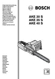
MOTOZAPPA<br />
MOTOR-HOE<br />
MOTOBINEUSE<br />
MOTORHACKE<br />
MOTOAZADA<br />
MOTOENXADA<br />
Istruzioni d'uso<br />
Operating instructions<br />
Mode d'emploi<br />
Bedienungsanweisung<br />
Manual de instrucciones<br />
Instruções de uso
1<br />
4<br />
2<br />
5<br />
I A RICHIESTA<br />
GB OPTIONAL<br />
F SUR DEMANDE<br />
D AUF WUNSCH<br />
E A DEMANDA<br />
P A PEDIDO<br />
3<br />
6
7<br />
9<br />
3<br />
2<br />
1<br />
10<br />
8<br />
11
12 13<br />
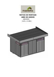
Etich<strong>et</strong>ta indicazione filo r<strong>et</strong>romarcia<br />
Label for reverse wire<br />
Plaqu<strong>et</strong>te pour fil à marche arrière<br />
Aufkleber fuer rg-bowdenzug<br />
Etiqu<strong>et</strong>a indicación hilo marcha-atrás<br />
Etiqu<strong>et</strong>a indicação de espia marcha-atrás
• Leggere il manuale prima di usare la macchina<br />
• Read the instructions manual before operating<br />
on the machine<br />
• Lire le mode d'emploi avant l'usage<br />
• Lesen Sie die Gebrauchsanweisung vor der<br />
Inb<strong>et</strong>riebnahme<br />
• Antes de proceder a montar la màquina lea<br />
atentamente estas instrucciones<br />
• Ler o manual das instruções antes do uso<br />
• Etich<strong>et</strong>ta acceleratore<br />
• Label accelerator<br />
• Plaqu<strong>et</strong>te acceleration<br />
• Gasaufkleber<br />
• Etiqu<strong>et</strong>a acelerador<br />
• Plaqu<strong>et</strong>a do acelerador<br />
• Attenzione: rotazione fresa<br />
• Danger tiller rotation<br />
• Attention: danger rotation fraise<br />
• Achtung: frasenrotation<br />
• Atencion: la fresa gira<br />
• Atenção: rotação da fresa<br />
• Marcia avanti<br />
• Forward drive<br />
• Marche avant<br />
• Fahrantrieb vorwärts<br />
• Marcha adelante<br />
• Velocidade para frente<br />
• Manopola di regolazione per rotazione<br />
manubrio<br />
• Adjusting knob for handlebar rotation<br />
• Man<strong>et</strong>te de reglage pour rotation mancherons<br />
• Handgriffverstellung für holmdrehung<br />
• Tuerca de regolacion para rotacion de manillar<br />
• Manípulo de regulação para a rotação do<br />
guiador<br />
• R<strong>et</strong>romarcia<br />
• Reverse drive<br />
• Marche arrière<br />
• Rückwärtsgang<br />
• Marcha atrás<br />
• Marcha atrás
Indice<br />
Introduzione<br />
Condizioni di utilizzazione<br />
Suggerimenti di sicurezza<br />
Istruzioni d' uso<br />
Trasporto<br />
Montaggio<br />
Regolazione<br />
Manutenzione<br />
Dati tecnici<br />
Rumore aereo<br />
Accessori<br />
Pericolo grave per<br />
l'incolumità dell'operatore e<br />
delle persone esposte.<br />
INTRODUZIONE<br />
Gentile cliente,<br />
lei ha acquistato una nuova attrezzatura. La ringraziamo per la fiducia accordata ai ns. prodotti e le<br />
auguriamo un piacevole utilizzo della sua macchina.<br />
Abbiamo creato queste istruzioni per I’uso allo scopo di assicurare, fin dall’inizio, un funzionamento privo d’inconvenienti.<br />
Seguite attentamente questi consigli, avr<strong>et</strong>e la soddisfazione di possedere per molto tempo una macchina che<br />
funziona a dovere. Le nostre macchine, prima di essere fabbricate in serie, vengono collaudate in maniera molto rigorosa<br />
e, durante la fabbricazione vera e propria, sono sottoposte e severi controlli. Ciò costituisce, per noi e per voi, la<br />
migliore garanzia che si tratta di un prodotto di riprovata qualità.<br />
Questa macchina é stata sottoposta a rigorosi test neutrali, nel paese d’origine, e risponde alle norme di<br />
sicurezza in vigore. Per garantire questo, é necessario utilizzare esclusivamente ricambi originali.<br />
L’utilizzatore perde ogni diritto di garanzia qualora vengono utilizzati ricambi non originali.<br />
Con riserva di variazioni tecnico-costruttive.<br />
Per informazioni e per ordinazioni di pezzi di ricambio si prega citare il numero di articolo e il numero di produzione.<br />
�� �� ��DATI �� �� PER L'IDENTIFICAZIONE (FIG. 1) L'<strong>et</strong>ich<strong>et</strong>ta con i dati della macchina e il numero di matricola è<br />
sul fianco sinistro della <strong>motozappa</strong>, sotto il <strong>motor</strong>e. Nota - Nelle eventuali richieste di Assistenza Tecnica o nelle ordinazioni<br />
delle Parti di Ricambio, citare sempre il numero di matricola della <strong>motozappa</strong> interessata.<br />
�� �� ��CONDIZIONI �� ��<br />
DI UTILIZZAZIONE - LIMITI D'USO La <strong>motozappa</strong> è prog<strong>et</strong>tata e costruita per eseguire<br />
operazioni di zappatura del terreno. La <strong>motozappa</strong> deve lavorare esclusivamente con attrezzi e con ricambi originali.<br />
Ogni utilizzo diverso da quello sopra descritto è illegale; comporta, oltre al decadimento della garanzia, anche<br />
un grave pericolo per l'operatore e per le persone esposte.<br />
�� �� ��NORME �� �� DI SICUREZZA<br />
Attenzione: prima del montaggio e la messa in funzione leggere attentamente il libr<strong>et</strong>to istruzione. Le<br />
persone che non conoscono le norme di utilizzazione non possono usare la macchina.<br />
1 Impedire l’uso ai minori di 16 anni<br />
2 Controllare che i bambini stiano lontani. Si<strong>et</strong>e responsabili dei danni causati a terzi.<br />
3 Togliere i corpi estranei dal terreno prima di iniziare le operazioni di fresatura. Lavorare solo alla luce del<br />
giorno oppure in presenza di una buona illuminazione artificiale.<br />
4 Non m<strong>et</strong>tere in moto la macchina quando si è davanti alla fresa, nè avvicinarsi ad essa quando è in moto.<br />
Tirando la cordina di avviamento del <strong>motor</strong>e, le frese e la macchina stessa devono rimanere ferme (se le frese<br />
girano intervenire sul registro di regolazione del tendicinghia).<br />
5 Durante il lavoro, per maggiore protezione, vanno indossate calzature robuste e pantaloni lunghi. Fare<br />
attenzione, perché il pericolo di ferirsi le dita o i piedi con la macchina in funzione è molto elevato. Camminare,<br />
ITALIANO<br />
1
ITALIANO<br />
2<br />
non correre, durante il lavoro.<br />
6 Durante il trasporto della macchina e tutte le operazioni di manutenzione, pulitura, cambio degli attrezzi, il <strong>motor</strong>e deve essere spento.<br />
7 Allontanarsi dalla macchina non prima di aver spento il <strong>motor</strong>e.<br />
8 Non avviare la macchina in locali chiusi dove si possono accumulare esalazioni di carbonio.<br />
9 AVVERTENZA La benzina è altamente infiammabile: Non fare il pieno di benzina in locali chiusi né con il <strong>motor</strong>e in moto, non fumare e fare<br />
attenzione alle fuoriuscite di combustibile dal serbatoio. In caso di fuoriuscita non tentare di avviare il <strong>motor</strong>e, ma allontanare la macchina dall’area<br />
interessata evitando di creare fonti di accensione finchè non si sono dissipati i vapori della benzina. Rim<strong>et</strong>tere a posto corr<strong>et</strong>tamente i tappi del<br />
serbatoio e del contenitore della benzina.<br />
10 Attenzione al tubo di scarico. Le parti vicine possono arrivare a 80°. Sostituire i silenziatori usurati o dif<strong>et</strong>tosi.<br />
11 Non usare la <strong>motozappa</strong> su forti pendenze, potrebbe ribaltarsi. Sui pendii lavorare sempre trasversalmente, mai in salita o discesa ed esercitare<br />
la massima cautela nei cambi di direzione.<br />
12 Prima di iniziare il lavoro con la macchina procedere ad un controllo visivo e verificare che tutti i sistemi antinfortunistici, di cui essa è dotata, siano<br />
perf<strong>et</strong>tamente funzionanti. E’ severamente vi<strong>et</strong>ato escluderli o manom<strong>et</strong>terli. Sostituire i particolari danneggiati od usurati.<br />
13 Ogni utilizzo improprio, le riparazioni eff<strong>et</strong>tuate da personale non specializzato o l’impiego di ricambi non originali, comportano il decadimento<br />
della garanzia e il declino di ogni responsabilità della ditta costruttrice.<br />
�� �� ��DISPOSITIVO �� ��<br />
DI SICUREZZA (Fig. 13) Tutte le motozappe sono dotate di dispositivo antinfortunistico. D<strong>et</strong>to dispositivo causa il disinnesto<br />
automatico della trasmissione quando si rilascia la relativa leva di comando (2 - 8).<br />
�� �� ��NOTE �� �� PER IL LAVORO CON LA MOTOZAPPA A <strong>motor</strong>e avviato appoggiare i coltelli sul terreno e, tenendo saldamente la <strong>motozappa</strong>,<br />
infilare nel terreno il braccio del timone. Tirare la leva della frizione sulla stegola per far pen<strong>et</strong>rare la fresa nel terreno. Sollevando leggermente la fresa mediante<br />
le stegole, la <strong>motozappa</strong> si muove in avanti. Il braccio del timone durante il lavoro deve rimanere sempre infilato nel terreno. Applicazioni: Lavorazione<br />
di terreni leggeri o di media pesantezza. Lavorazione del terreno (fresatura/sminuzzamento). Dissodamento del terreno (eliminazione infestanti).<br />
Incorporamento di compost o fertilizzanti, ecc. Attenzione: La <strong>motozappa</strong> non è adatta per la lavorazione di terreni ricoperti di cotica erbosa compatta/prato.<br />
Se ne sconsiglia inoltre l'uso sui terreni pi<strong>et</strong>rosi.<br />
�� �� ��TRASPORTO �� ��<br />
Per la movimentazione è previsto l'uso di carrello elevatore. Le forche, allargate al massimo consentito, vanno inserite negli<br />
appositi spazi del pall<strong>et</strong>. La massa della macchina è indicata nella <strong>et</strong>ich<strong>et</strong>ta della marcatura e riportata nei dati tecnici.<br />
�� �� ��MONTAGGIO �� ��<br />
DELLA MOTOZAPPA La <strong>motozappa</strong> viene consegnata a destinazione, salvo accordi diversi, smontata e sistemata in un<br />
adeguato imballaggio. Per compl<strong>et</strong>are il montaggio della <strong>motozappa</strong> osservare la seguente procedura.<br />
�� �� ��BRACCIO �� �� DEL TIMONE E TIMONE a richiesta (Fig. 2) Posizionare il braccio del timone (fig. 3, part. 1) in corrispondenza del foro<br />
centrale (2), bloccare con perno (3) e la spina di sicurezza (4). Infilare il timone (5) nella parte terminale del braccio, bloccare con il perno (6) e spina di sicurezza<br />
(7). La ruota di trasporto serve unicamente per il trasporto della <strong>motozappa</strong>. In fase di lavoro, smontarla come segue: rimuovere la spina di sicurezza e<br />
sfilare la ruota dal supporto tirando verso il basso.<br />
�� �� ��TIMONE �� �� (Fig. 3) Posizionare il timone (1) in corrispondenza del foro centrale, poi bloccare con la spina di sicurezza.
�� �� ��SUPPORTO �� ��<br />
STEGOLE E STEGOLE (Fig. 4) Montare il supporto (1) sulla <strong>motozappa</strong> tramite quattro viti (2) e risp<strong>et</strong>tive rondelle (3).<br />
(Prima nei fori 2, poi nelle asole). Attenzione - Le rondelle con diam<strong>et</strong>ro maggiore devono essere montate in corrispondenza delle asole (4). Fissare le<br />
stegole (5) al supporto (1) per mezzo delle viti (6) rondelle elastiche (7) e dadi (8). Regolare l'altezza delle stegole agendo sulle viti (2) che fissano il supporto<br />
(viti in corrispondenza delle asole).<br />
�� �� ��MONTAGGIO �� ��<br />
CAVO ACCELERATORE (Fig. 5) Posizionare, a fondo corsa, la leva ( 1 ) installata sul <strong>motor</strong>e come indicato dalla freccia<br />
“A,, in figura. Portare a fine corsa il man<strong>et</strong>tino comando acceleratore (2) installato sulla stegola come indicato dalla freccia “B,, in figura. Inserire il cavo (3) nel<br />
foro (4), fissare la guaina (5) con l’apposito cavallotto (6) e bloccare con la vite (7). Attenzione: il man<strong>et</strong>tino acceleratore in posizione “stop’, deve spegnere il<br />
<strong>motor</strong>e.<br />
�� �� ��CAVO �� �� COMANDO TENDICINGHIA (Fig. 6) Il cavo di comando è già collegato alla molla tendicinghia e occorre collegarlo alla leva installata<br />
sul manubrio nel modo seguente: inserire il filo (3) e il registro (4) nel foro tagliato del nasello (5); inserire il terminale (1) nel foro (2).<br />
�� �� ��MONTAGGIO �� ��<br />
COPERCHIO ANTERIORE TELAIO (Fig. 9) Montare il coperchio anteriore inserendo le al<strong>et</strong>te laterali di aggancio (1)<br />
nelle asole del telaio (2) fissandolo con le viti (3) e la rondella (4).<br />
�� �� ��REGISTRAZIONE �� ��<br />
DEI COMANDI (Fig. 10) attenzione - La fresa deve iniziare a girare non prima d'aver agito sui risp<strong>et</strong>tivi comandi. Questo<br />
si ottiene intervenendo sui registri dei fili. Inoltre la leva che comanda la marcia di zappatura deve avviare la fresa solo dopo aver compiuto m<strong>et</strong>à della propria<br />
corsa; quando poi la stessa è a fine corsa (posizione di lavoro) la molla di carico del tendicinghia (1) si deve allungare di circa 6-8 mm. Se il registro (2) non è<br />
sufficiente ad ottenere d<strong>et</strong>te condizioni (il registro è arrivato a fondo fil<strong>et</strong>tatura) provvedere a regolare la cinghia trapezoidale spostando il <strong>motor</strong>e lungo le<br />
asole del telaio dove è fissato.<br />
�� �� ��REGOLAZIONE �� ��<br />
DEL TIMONE (Fig. 11) Per ottenere una buona fresatura e un avanzamento regolare della <strong>motozappa</strong>, regolare il timone<br />
nel modo seguente: Fresatura di terreni duri: Sfilare la spina (1) e il perno (2), portare il timone (3) nella posizione (4). Fresatura di terreni morbidi:<br />
Sfilare la spina (1) e il perno (2), portare il timone (3) nella posizione 1. Al timone in posizione 1 corrisponde una grande profondità di lavorazione. Al timone in<br />
posizione 4 corrisponde una scarsa profondità di lavorazione.<br />
����� ISTRUZIONI D'USO Dopo le operazioni di montaggio e regolazione la <strong>motozappa</strong> è pronta per lavorare.<br />
ATTENZIONE. Prima di avviare il <strong>motor</strong>e controllare sempre che la macchina sia in perf<strong>et</strong>te condizioni di funzionamento.<br />
- Istruzioni Motore: Leggere attentamente il libr<strong>et</strong>to istruzioni allegato del relativo <strong>motor</strong>e.<br />
- Controllare che il filtro aria sia ben pulito.<br />
- Riempire il serbatoio di carburante del tipo indicato dalle specifiche nel libr<strong>et</strong>to del <strong>motor</strong>e usando un imbuto con filtro.<br />
- Non modificare la taratura del regolatore di velocità di rotazione del <strong>motor</strong>e e non far raggiungere ad esso una condizione di sopravvelocità.<br />
- Regolare il manubrio all’altezza più adatta al lavoro da eseguire.<br />
- Messa in moto del <strong>motor</strong>e (Fig.13) Aprire il rubin<strong>et</strong>to del carburante (per i <strong>motor</strong>i provvisti), spingere fino a m<strong>et</strong>à la lev<strong>et</strong>ta dell’acceleratore posto sul<br />
manubrio (part.1) se il <strong>motor</strong>e è freddo, azionare il dispositivo di starter sul carburatore, afferrare la maniglia di avviamento e dare uno strappo energico.<br />
Avviato il <strong>motor</strong>e riportare, dopo i primi scoppi, lo starter nella posizione di riposo.<br />
ITALIANO<br />
3
ITALIANO<br />
4<br />
- Marcia avanti (Fig. 7) : Impugnare il manubrio e premere il fermo di sicurezza (3) che impedisce l’innesto accidentale delle frese. Tirare la leva<br />
avanzamento (1) per tutta la sua corsa.<br />
- Marcia indi<strong>et</strong>ro (Fig. 7) : rilasciare la leva avanzamento (1) , se innestata, e tirare verso di sé l’altra leva (2) posta sul manubrio, dopo aver<br />
premuto il fermo di sicurezza (3).<br />
- Questa <strong>motozappa</strong> è prog<strong>et</strong>tata per ridurre al minimo le emissioni di vibrazioni e rumore, tuttavia è buona norma intervallare lavori di lunga<br />
durata con piccole pause.<br />
- Fine lavoro: terminato il lavoro, per arrestare il <strong>motor</strong>e, portare la leva acceleratore nella posizione di minimo.<br />
�� �� ��MANUTENZIONE �� ��<br />
DELLE FRESE A ZAPPETTE (Fig. 8) Pulire i mozzi delle frese (1), l'albero porta-frese (2) e la parte tagliente delle<br />
zapp<strong>et</strong>te (3) dai residui di terra, erba, fili di ferro ecc. ecc.<br />
����� RIMESSAGGIO E MANUTENZIONE PERIODICA Mantenere serrati tutti i dadi, i bulloni e le viti per garantire il funzionamento della<br />
macchina nelle condizioni di sicurezza. Lasciar raffreddare la macchina prima di immagazzinarla e comunque non riporla con benzina nel serbatoio all’interno<br />
di un edificio, dove i vapori possono raggiungere una fiamma libera o una scintilla. Per ridurre il pericolo di incendio mantenere il <strong>motor</strong>e, il silenziatore e la<br />
zona di immagazzinamento della benzina liberi da foglie, erba e grasso in eccesso. PER VERIFICARE IL LIVELLO (Fig. 12) M<strong>et</strong>tere la macchina in piano.<br />
Svitare il tappo e controllare che l'olio sia a livello inferiore del foro. Il tappo di riempimento e svuotamento corrisponde al livello olio. Olio: SAE 80 per<br />
trasmissioni.<br />
�� �� ��MANUTENZIONE �� ��<br />
MOTORE (vedere la pubblicazione specifica) Attenzione (Per i <strong>motor</strong>i 4 tempi) La <strong>motozappa</strong> viene consegnata<br />
con il <strong>motor</strong>e senza olio. Riempire il serbatoio finchè l'olio inizia a traboccare, capacità circa 0,500 kg. Usare olio tipo MULTIGRADE con viscosità 10-40 w.<br />
�� �� ��DESCRIZIONE �� ��<br />
DEI COMANDI (Fig. 13) 1. Leva comando acceleratore. - 2. Leva comando marcia di zappatura (dispositivo antinfortunistico).<br />
- 3. Maniglia per avviamento a strappo (dispositivo autoavvolgente). - 4. Dispositivo tendicinghia - 5. Timone per regolazione fresatura. - 6. Frese - 7. Riparo<br />
fresa - 8. Leva comando RM (dispositivo antinfortunistico).<br />
�� �� ��CARATTERISTICHE �� ��<br />
TECNICHE Fresa: a zapp<strong>et</strong>te per larghezza di lavoro di 50 cm, compl<strong>et</strong>a di carter di protezione. La velocità massima di<br />
rotazione della fresa è di 140 giri/min. circa. Cambio: marcia avanti o marcia avanti + r<strong>et</strong>romarcia. Peso: Peso della <strong>motozappa</strong> compl<strong>et</strong>a di fresa da 50<br />
cm, circa 41 kg. Dimensioni: Lunghezza massima 1,220 m. Larghezza massima 0,50 m. Altezza 1,00 m.<br />
�� �� ��RUMORE �� �� AEREO E VIBRAZIONI Valore di pressione acustica al posto di lavoro secondo EN 709 L A e q = 77,8 dB (A). Vibrazioni alle stegole<br />
secondo EN 709 e ISO 5349. Valore rilevato = 5,5 m/s2 .<br />
��ACCESSORI - ATTREZZI UTILIZZABILI 1) Allargamento frese cm. 80 + protezione - 2) Coppia dischi proteggipiante - 3) Rincalzatore<br />
ad ali fisse con attacco - 4) Arieggiatore prato a molle. L'allargamento è equipaggiato con 2 frese per una larghezza totale di lavoro di cm. 80 e di<br />
2 ripari aggiuntivi, per protezione frese, bloccati con 2 viti ciascuna sulla protezione centrale. Al termine degli ultimi elementi fresanti si possono fissare,<br />
per mezzo di viti, dei dischi del Ø di cm. 25 per proteggere le piante. Il rincalzatore si usa per fare dei solchi nel terreno prima della semina. Il rincalzatore si<br />
fissa alla macchina, al posto dello sperone, e si blocca con una spina fermata da una spilla a R.
List of contents<br />
Introduction<br />
Conditions of use<br />
Saf<strong>et</strong>y measures<br />
Instructions for operating<br />
Transport<br />
Assembly<br />
Regulating<br />
Maintenance<br />
Technical D<strong>et</strong>ails<br />
Noise<br />
Accessories<br />
Serious risk for operator<br />
and bystander saf<strong>et</strong>y.<br />
INTRODUCTION<br />
Dear Customer:<br />
Thank you for your confidence in purchasing our products. We wish you to enjoy using our machines.<br />
The following working instructions have been issued to ensure you a reliable running from the beginning. If you carefully<br />
follow such information the machine will operate with compl<strong>et</strong>e satisfaction have a long service life.<br />
Our machines are tested under the most severe conditions before being put into production and are subjected to strict<br />
continuous tests during manufacturing stages. This present unit has been tested in the country of origin by<br />
independent testing authorities in accordance with strict work norms and saf<strong>et</strong>y standards.<br />
When required, only original spare parts must be used to maintain guaranteed function and saf<strong>et</strong>y levels.<br />
The operator forfeits any claims which may arise, if the machine shows to be fitted with components<br />
other than original spare parts. Subject to changes in design and construction without notice. For any questions or<br />
further information and spare part orders,we need to be informed of the unit serial number printed on the side of the<br />
machine.<br />
�� �� ��IDENTIFICATION �� ��<br />
DATA (Fig. 1) The tag plate with the machine data and Serial N° is on the left side of the<br />
cultivator under the engine. Note - Always state your <strong>motor</strong> cultivator serial number when you need Technical Service<br />
or Spare Parts.<br />
�� �� ��CONDITIONS �� ��<br />
AND LIMITATIONS OF USE This <strong>motor</strong>-<strong>hoe</strong> is designed and built to <strong>hoe</strong> the land. The<br />
<strong>motor</strong>-<strong>hoe</strong> must only be used with original equipment and spares. Any use other than those described above is<br />
prohibited and will involve, in addition to cancellation of the warranty, serious risk for the operator and bystanders.<br />
�� �� ��SAFETY �� �� PRECAUTIONS<br />
Attention: Before assembly and putting into operation, please read the operating instruction carefully.<br />
Persons not familiar with these instructions should not use the machine.<br />
1 Persons under 16 should not be allowed to use the machine.<br />
2 When operating the machine, the user should ensure that no others, particularly children, are standing in<br />
the area. Please, remember that you are responsible for the safe operating of your machine vis-a-vis third<br />
persons.<br />
3 Before starting to mill, remove any foreign bodies from the soil. Work only in daylight or in good artificial light.<br />
4 Do not start the machine if standing in front of the rotary cutter, neither g<strong>et</strong> near the machine when working. If<br />
pulling the starter short rope, the rotary cutter and the machine have to standstill (if rotation is experienced, take<br />
action on the belt str<strong>et</strong>cher control nut).<br />
5 During working operations, for protection purposes, it is recommended to wear technical/strong s<strong>hoe</strong>s and<br />
long trousers. Be careful , because when machine is operating the danger to be wounded in the toes or fe<strong>et</strong> is<br />
really high. Walk, never run with the machine.<br />
ENGLISH<br />
5
ENGLISH<br />
6<br />
6 During the machine transport and all the maintenance, cleaning, equipment change operations, the engine must be switched off.<br />
7 Before leaving the machine, please switch the engine off.<br />
8 Do not switch the machine on in closed rooms/areas where you can have carbon monoxide exhalations.<br />
9 WARNING !! The p<strong>et</strong>rol/gasoline is highly inflammable: Don’t fill the tank neither in closed areas, nor when engine is on, don’t smoke and be careful<br />
to the p<strong>et</strong>rol/gasoline loss from the tank. In case of leak, don’t try to switch the engine on but move the machine away from the area in order to avoid<br />
ignition source until the gasoline vapours fade away. Re-place the tank caps and the gasoline box.<br />
10 Keep attention to the exhaust pipe. The parts near the pipe can reach 80°C.<br />
Replace the defective and/or worn out silencers Burn hazards !!!.<br />
11 Don’t use the <strong>motor</strong><strong>hoe</strong> on steep slopes: it could overturn!. On slope it is recommended to work crosswise, neither in slope nor in descent and be<br />
vary careful during any change of direction.<br />
12 Before putting the machine into operations, check it visually and make sure all the accident prevention measures are working. It is absolutely<br />
forbidden to exclude and/or to tamper with them. Replace worn or damaged elements.<br />
13 In case the machine is incorrectly used, and/or the repairs are performed by non-authorized technical staff, and/or fitted by equispare parts other<br />
then original ones: any use other than that described above is prohibited and will involve the cancellation of the warranty and the refuse all<br />
responsability from the manufacturer.<br />
�� �� ��SAFETY �� �� FEATURE (Fig. 13) All <strong>motor</strong>-<strong>hoe</strong>s are provided with a saf<strong>et</strong>y feature which acts. The device causes the transmission to disconnect<br />
automatically anytime the respective control lever is released (2 - 8).<br />
�� �� ��NOTES �� �� ON WORK WITH THE MOTOR-HOE With the engine running, rest the tines on the ground, and firmly holding the <strong>motor</strong>-<strong>hoe</strong>,<br />
insert the tool bar arm into the soil. Pull the clutch lever on the handlebar to allow the disks to bite into the soil. The <strong>motor</strong>-<strong>hoe</strong> will move forwards when the<br />
handlebars are used to slightly lift the disks. The tool bar arm must always remain in the soil during work. Uses: Light or medium textured soil working. Soil<br />
working (<strong>hoe</strong>ing/breaking-up). Soil tillage (weeding). Ploughing in compost or fertilizers, <strong>et</strong>c. Attention: The <strong>motor</strong>-<strong>hoe</strong> is unsuitable for working in soils<br />
covered by thick grass/lawns. It is also unadvisable to use the implement on stony soils.<br />
�� �� ��TRANSPORT �� ��<br />
A forklift truck should be used to move the machine. The forks should be opened as far as possible and inserted into the pall<strong>et</strong>. The<br />
weight of the machine is given on the Manufacturer's data plate tog<strong>et</strong>her with the other technical information.<br />
�� �� ��HOW �� �� TO ASSEMBLE YOUR MOTOR-HOE Unless otherwise agreed, the <strong>motor</strong> cultivator is delivered disassembled and placed in a<br />
packing case. For assembly to be compl<strong>et</strong>ed, the step/by/step procedure is as follows.<br />
�� �� ��DRAWBAR �� ��<br />
ARM AND DRAWBAR optional (Fig. 2) Place the drawbar arm (1 fig.3) close the central hole (2), lock with pin (3) and saf<strong>et</strong>y<br />
pin (4). Insert drawbar (5) into the arm end (1 ), secure with pin (6) and saf<strong>et</strong>y pin (7). The transport wheel is only used to convey the <strong>motor</strong>-<strong>hoe</strong>. During the work<br />
phase, demount the wheel as follows: remove the saf<strong>et</strong>y pin and take the wheel off the support by pulling it downwards.<br />
�� �� ��DRAWBAR �� ��<br />
(Fig. 3) Insert drawbar (1) into the central hole, insert the washer and lock with saf<strong>et</strong>y pin.<br />
����� HANDLEBARS SUPPORT AND HANDLEBARS (Fig. 4) Secure support (1) to <strong>motor</strong>cultivator through the four screws (2) and washers
(3). (First in holes and then in slots). Attention - Larger diam<strong>et</strong>er washers are to be fitted to match slots (4). Mount handlebars (5) to support (1) by means of<br />
screws (6), lock washers (7) and nut (8). Adjust handlebars height through screws (2) which hold the support (move screws along slots).<br />
�� �� ��HOW �� �� TO MOUNT THE ACCELERATOR WIRE Fig. 5 Position the lever (1) on the engine at the end of its stroke as shown by arrow “A “ in<br />
the figure. Move the throttle lever(2) on the handlebar to the end of its stroke as shown by arrow “B “ in the figure. Insert wire (3) into hole (4), secure the sheath<br />
(5) with r<strong>et</strong>ainer (6) and screw (7). ATTENTION: in the position “stop” the throttle lever must stop engine.<br />
�� �� ��BELT �� �� STRETCHER DRIVING WIRE (Fig.6) Driving wire is already connected with the belt-str<strong>et</strong>ching spring; have it connected to the lever<br />
on handlebar as follows: Insert the wire (3) and the register (4) in hole cut in the prong. Engage sheath terminal (1) into hole (2).<br />
�� �� ��INSTALLING �� ��<br />
THE FRONT FRAME COVER (Fig. 9) Install the front cover by inserting the side attaching wingnuts (1) into the slots in the<br />
frame (2) and fix them with screw (3) and washer (4).<br />
�� �� ��CONTROL �� ��<br />
ADJUSTMENT (Fig. 10) Warning - The tiller should not start forward rotation before acting on respective controls. This obtained<br />
acting on the wire nuts. Besides, the lever controlling the <strong>hoe</strong>ing gear should start the tiller only after having compl<strong>et</strong>ed half-travel; when the lever has<br />
compl<strong>et</strong>ed its travel (working position) the belt-str<strong>et</strong>cher load spring (1) should extent from 6 to 8 mm. If nut (2) does not suffice to obtain such conditions (nut<br />
having reached the thread end) proceed to a preliminary adjustment of V-belt by moving the engine through slots of chassis where it is fixed.<br />
�� �� ��ADAPTING �� ��<br />
THE DRAWBAR (Fig. 11) To obtain a smooth forward movement and a good job, adjust the drawbar as follows: Hoeing hard<br />
soils: Remove pin (1) and plug (2). s<strong>et</strong> drawbar (3) to position 4. Hoeing soft soils: Remove pin (1) and plug (2). S<strong>et</strong> drawbar (3) to position 1. Tool bar position1<br />
corresponds to a deeper working depth. Tool bar position 4 corresponds to a more shallow working depth.<br />
����� INSTRUCTIONS<br />
Following the assembly & adjustment operations the <strong>motor</strong>-<strong>hoe</strong> is ready to start working.<br />
ATTENTION ! Before switching the engine on, carefully check if the <strong>motor</strong>-<strong>hoe</strong> is in perfect good repair.<br />
- Engine instructions: Carefully read the istructions bookl<strong>et</strong> anclosed to the relevant engine.<br />
- Check if the air filter is clean.<br />
- Fill the tank in as per the fuel described in the engine specifications and using a filter filling funnel.<br />
- Do not change the calibration of the speeds control rotation device of the engine in order not to over-speed it.<br />
- Adjust the handlebar to the requested position/height:<br />
- How to switch the engine on (Fig.13): Open the fuel cap (for the engine equipped like this), push to halway the accelerator lever on the handlebar<br />
(part.1) if the engine is cold, operate the starte device on the carbur<strong>et</strong>tor, bring the starter handle and pull energ<strong>et</strong>ically.<br />
When the engine is on, after some bursts/bangs, put the starter again at rest position,<br />
- Forward speed (Fig. 7) : Grip the handlebars and press the saf<strong>et</strong>y device (3) which is preventing the accidental tines connection. Pull the<br />
forward lever (1) all its way long.<br />
- Reverse speed (Fig. 7) : release the forward lever (1) and pull the other lever (2) on the handlebar towards you after having pressed the saf<strong>et</strong>y<br />
device (3).<br />
ENGLISH<br />
7
ENGLISH<br />
8<br />
- The present tiller has been projected in order to lower to the minimum the vibrations and noise levels. Anyhow we can advise you to stop<br />
working any now and then in case you would need to perform/work for a long period.<br />
- At the end of the work: when you finish the work, to stop the engine, bring the accelerator lever to the bottom gear or press the stop switcher<br />
on the engine.<br />
�� �� ��SERVICING �� ��<br />
FOR THE HOE TILLERS (Fig. 8) Clean the tiller hubs(1), the tiller-shaft (2) and the cutting <strong>hoe</strong> parts (3) making sure they are<br />
free from soil residues, grass, iron wires, <strong>et</strong>c. <strong>et</strong>c.<br />
�� �� ��MAINTENANCE �� ��<br />
ENGINE (see engine manual) Attention - The <strong>motor</strong>-cultivator is delivered without oil in engine. Replenish tank until oil<br />
overflows. Capacity O.500 kg approx. Use oil type MULTIGRADE viscosity to be 10 - 40 W.<br />
����� GARAGING AND SCHEDULED MAINTENANCE<br />
Keep attention that all the nuts ,screws and bolts are tightened in order to guarantee a good machine working on saf<strong>et</strong>y conditions. Leave the machine to cool<br />
before garaging anyhow don’t room it if the tank contains still contains some fuel as the vapours could reach some blazes or sparks. To lower the fire danger ,<br />
keep the engine , the silencer and the fuel area free from leaves , grass or greasy substances. TO CHECK THE OIL LEVEL (Fig. 12) Place the machine on<br />
a flat surface. Remove the filler cap and check if the oil is level with the bottom of the hole. The filler and emptying cap acts as the oil level. Top up with: SAE 80<br />
transmission oil.<br />
�� �� ��DESCRIPTION �� ��<br />
OF CONTROLS (Fig. 13) 1. Throttle lever - 2. Hoeing gear control lever (saf<strong>et</strong>y feature) - 3. Pull-out handle (Self-winding<br />
device) - 4. Belt-str<strong>et</strong>cher - 5. Tilling adjustment drawbar - 6. Cultivator blade - 7. Hoe shield - 8. Reversing lever (saf<strong>et</strong>y feature).<br />
�� �� ��TECHNICAL �� ��<br />
SPECIFICATION Tiller: fitted with <strong>hoe</strong>s. Working width 50 cm. The highest speed of rotation of the tiller is about 140 R.P.M.<br />
Transmission : single speed or single speed+reverse speed. Weight: weight of <strong>motor</strong>-cultivator in the working order provided with 50 cm <strong>hoe</strong>-tiller: 41 kg<br />
approx. Max length: 1,220 m. Max width: 0,500 - 0,800 m. Height: 1,000 m.<br />
�� �� ��NOISE �� �� AND VIBRATION LEVEL Noise level when working in compliance with EN 709 L A e q = 77,8 dB (A). Handlebar vibration in compliance<br />
with EN and ISO 5349. Level d<strong>et</strong>ected = 5,5 m/s2 .<br />
�� �� �� �� ��ACCESSORIES<br />
- ATTACHMENTS 1) Expanding the 80 cm. rotary cultivator + guard - 2) Pair of plant protecting disks - 3)<br />
Ridging body with hitch - 4) Sprung ridger. The expansion has two cultivators for a total working width of 80 cm. and two extra guard sections to<br />
protect the rotary cultivators. Each section is attached to the centre guard with two screws. 25 cm. diam<strong>et</strong>er disks can be attached with screws to the end<br />
cultivators as plant protection. The ridging body is used to prepare furrows in the soil before sowing. The ridging unit is fixed to the machine in place of the<br />
headstock and is locked by means of a pin and a lock pin.
Table des matières<br />
Introduction<br />
Conditions d'utilisation<br />
Mesures de sécurité<br />
Conseils d'utilisation<br />
Transport<br />
Montage<br />
Réglage<br />
Entr<strong>et</strong>ien<br />
Données techniques<br />
Niveau sonore<br />
Accessoires<br />
Danger grave pour<br />
l'intégrité de l'opérateur <strong>et</strong><br />
des personnes exposées.<br />
INTRODUCTION<br />
Cher client,<br />
Vous venez d’acquérir un nouvel appareil. Nous vous remercions de la confiance que vous nous<br />
témoignez <strong>et</strong> vous souhaitons beaucoup de satisfaction dans son utilisation. Afin de garantir d’emblée<br />
un fonctionnement sans accrocs nous avons créé c<strong>et</strong>te notice d’utilisation. Si vous observez exactement<br />
les indications suivantes votre appareil fonctionnera toujours à votre entière satisfaction pendant longtemps.<br />
Nos appareils avant la fabrication en série, sont mis à I’essai dans les conditions les plus sévères <strong>et</strong>, durant<br />
la fabrication même, sont soumis constamment à des contrôles très stricts. De ce fait, nous sommes sûrs<br />
de la qualité de nos produits <strong>et</strong> pouvons vous garantir une machine à toute épreuve.<br />
C<strong>et</strong> appareil a été testé <strong>et</strong> contrôlé par un laboratoire indépendant selon des normes de travail <strong>et</strong> de<br />
sécurité très sévères. Pour conserver à c<strong>et</strong> appareil les qualités <strong>et</strong> performances prévues, n’utilisez<br />
que des pièces détachées d’origine. La qualité du travail <strong>et</strong> votre sécurité en dépendent. L’utilisateur<br />
perd tous ses droits à la garantie lorsqu’il modifie l’appareil par l’adjonction de pièces détachées<br />
non d’origine. Dans le but d’améliorer nos produits nous nous réservons le droit d’y apporter des<br />
modifications. Pour toutes questions ou commandes concernant les pièces détachées, prière d’indiquer le<br />
numéro de référence.<br />
�� �� ��DONNÉES �� ��<br />
D’IDENTIFICATION L’étiqu<strong>et</strong>te avec les caractéristiques de la machine <strong>et</strong> le numéro<br />
de matricule se trouve sur le côté gauche de la <strong>motobineuse</strong>, sous le moteur. Note - Fournir le numéro de<br />
série de la <strong>motobineuse</strong> pour toute demande d’assistance technique ou commande de pièces.<br />
�� �� ��CONDITIONS �� ��<br />
D’UTILISATION - LIMITES D’EMPLOI La <strong>motobineuse</strong> est conçue <strong>et</strong> réalisée<br />
pour biner le terrain. Elle ne peut travailler exclusivement qu’avec des outils <strong>et</strong> des pièces de rechange<br />
d’origine. Toute utilisation différente de celle préconisée est illégale <strong>et</strong> entraîne l’annulation de la garantie,<br />
mais représente aussi un danger grave pour l’opérateur <strong>et</strong> les personnes exposées.<br />
�� �� ��MESURES �� ��<br />
DE SÉCURITÉ<br />
Attention: lire attentivement le manuel d’instructions avant de procéder au montage <strong>et</strong> à la mise en<br />
marche. La machine ne doit être utilisée que par des personnes en connaissant le mode d’emploi.<br />
1 Interdire l’emploi de la machine aux personnes de moins de 16 ans.<br />
2 Veiller à ce qu’aucun enfant ne se trouve à proximité. N’oubliez pas que vous êtes responsables des<br />
dommages éventuels causés à des tiers.<br />
3 Débarrasser le terrain au maximum de ses déch<strong>et</strong>s avant de commencer les opérations de binage.<br />
4 Ne pas m<strong>et</strong>tre en marche la machine lorsqu’on se trouve devant la fraise <strong>et</strong> ne pas s’y approcher<br />
lorsqu’elle est en marche. Lorsqu’on tire sur la corde du lanceur, les fraises <strong>et</strong> la machine ne doivent<br />
pas se m<strong>et</strong>tre en marche (si c’était le cas, agir sur la vis de réglage du tendeur de courroie).<br />
FRANÇAIS 9
FRANÇAIS 10<br />
5 Pour bénéficier d’une meilleure protection durant le travail, il est nécessaire de porter des chaussures robustes <strong>et</strong> un pantalon long. Faire<br />
particulièrement attention dans la mesure où les risques de blessures aux doigts ou aux pieds sont très élevés lorsque la machine est en<br />
marche.<br />
6 Durant le transport de la machine <strong>et</strong> toutes les opérations d’entr<strong>et</strong>ien, de n<strong>et</strong>toyage ou de changement d’outils, le moteur doit être à l’arrêt.<br />
7 Ne jamais s’éloigner de la machine avant d’en avoir éteint le moteur.<br />
8 Ne pas jamais m<strong>et</strong>tre en route la machine dans des locaux clos dans lesquels pourraient s’accumuler des émanations de carbone.<br />
9 MISE EN GARDE L’essence est hautement inflammable:Ne pas faire le plein d’essence dans des locaux clos <strong>et</strong> lorsque le moteur est en<br />
marche; ne pas fumer ; veiller à ce que le combustible ne déborde du réservoir. En cas de débordement, ne pas tenter de m<strong>et</strong>tre en route<br />
le moteur, mais éloigner la machine de la zone concernée en évitant de créer des sources d’inflammation jusqu’à ce que les vapeurs<br />
d’essence se soient dissipées. Rem<strong>et</strong>tre correctement en place les bouchons du réservoir <strong>et</strong> du récipient contenant l’essence.<br />
10 Attention au pot d’échappement. Les parties avoisinantes peuvent atteindre des températures proches de 80°C. Remplacer les silencieux usés<br />
ou défectueux.<br />
11 Ne pas utiliser le <strong>motobineuse</strong> en présence de pentes raides car il pourrait se r<strong>et</strong>ourner. Le travail en pente doit toujours se faire de travers, jamais<br />
en montée ni en descente ; prêter une extrême attention aux changements de direction.<br />
12 Avant de commencer le travail, effectuer un contrôle visuel de la machine pour vérifier si tous les systèmes contre les accidents du travail dont elle<br />
est équipée fonctionnent parfaitement. Il est formellement interdit de les ôter ou de les altérer.<br />
13 Une utilisation impropre, des réparations défectueuses effectuées par un personnel non spécialisé, ou l’emploi de pièces de rechanges n’étant<br />
pas d’origine entraînent l’expiration de la garantie <strong>et</strong> exonèrent le constructeur de toute responsabilité.<br />
�� �� ��DISPOSITIF �� ��<br />
DE SÉCURITÉ (Fig. 13) Toutes les <strong>motobineuse</strong>s sont fournies d'un dispositif de sécurité. Ce dispositif produit le desembrayage<br />
automatique de la trasmission alors que le levier de commande correspondant est débloqué (2 - 8).<br />
�� �� ��INSTRUCTIONS �� ��<br />
POUR LE TRAVAIL AVEC LA MOTOBINEUSE Moteur en marche, poser les couteaux sur le sol <strong>et</strong>, en tenant<br />
fermement la <strong>motobineuse</strong>, introduire dans la terre le bras du timon. Tirer la man<strong>et</strong>te de la friction sur le mancheron pour faire pénétrer les disques dans le sol.<br />
Pour faire avancer la <strong>motobineuse</strong>, soulever légèrement les disques avec les mancherons. Pendant le travail, le bras du timon doit toujours demeurer dans<br />
le sol. Applications: Travail de terrains légers ou moyennement lourds. Travail du terrain (fraisage/émottage). Défrichage du terrain (élimination des<br />
mauvaises herbes). Epandage de compost ou de fertilisants, <strong>et</strong>c. Attention: La <strong>motobineuse</strong> n'est pas adaptée au travail sur terrain recouverts de gazon<br />
compact/pelouses. D'autre part, son usage est déconseillé sur les terrain pierreux.<br />
�� �� ��TRANSPORT �� ��<br />
Utiliser un chariot élévateur pour transporter la machine. Les fourches, réglées dans la position d'écartement maximum, seront<br />
introduites dans les espaces spécialement prévus de la pal<strong>et</strong>te. La masse de la machine est indiquée sur l'étiqu<strong>et</strong>te d'identification <strong>et</strong> reportée dans les<br />
caractéristiques techniques de la machine.<br />
�� �� ��MONTAGE �� ��<br />
DE LA MOTOBINEUSE Sauf accord contraire, la <strong>motobineuse</strong> est livrée démontée dans son emballage spécial. Pour effectuer<br />
le montage de la machine, suivre les instruction suivantes.<br />
��BRAS DU TIMON ET TIMON sur demande (Fig. 2) Positionner le bras du timon (1) a proximité du trou central (2), bloquer par le goujon<br />
(3) <strong>et</strong> la goupille (4). Introduire le timon (5) dans l’extrémité du bras (1), serrer au moyen du goujon (6) <strong>et</strong> de la goupille (7). La roue de transport n'est utilisée<br />
que pour le transport de la <strong>motobineuse</strong>. Avant de travailler, la démonter comme suit: enlever la broche de sûr<strong>et</strong>é <strong>et</strong> r<strong>et</strong>irer la roue du support en tirant vers le bas.
�� �� ��TIMON �� �� (Fig. 3) Positionner le timon (1) a promimité du trou central, insérer la rondelle <strong>et</strong> bloquer par la goupille.<br />
�� �� ��SUPPORT �� ��<br />
DES MANCHERONS ET MANCHERONS (Fig. 4) Fixer les supports (1) sur la <strong>motobineuse</strong> au moyen des quatre vis<br />
(2) <strong>et</strong> des rondelles correspondantes (3). (D'abord dans les 2 trous, puis dans les oeill<strong>et</strong>s). Attention - Les rondelles de diamètre supérieur doivent<br />
être montée en face des oeill<strong>et</strong> (4). Fixer les mancherons (5) au support (1) avec des vis (6), des rondelles souples (7) <strong>et</strong> des écrous (8). Régler<br />
la hauteur des mancherons en déplaçant, dans les trous spéciaux de réglage.<br />
�� �� ��MONTAGE �� ��<br />
DU CABLE DE L’ACCÉLÉRATEUR (Fig. 5) Amener le levier (1 ) installe sur le moteur a fin de course comme indique par la<br />
flèche “A’, en figure. Amener la man<strong>et</strong>te de gaz (2) installe sur le mancheron a fin de course comme indique par la flèche “B,, en figure. Introduire le câble (3)<br />
dans le trou (4), fixer la gaine (5) au moyen du bande (6) <strong>et</strong> de la vis (7). ATTENTION: il faut que la man<strong>et</strong>te de gaz arrête le moteur dans la position “stop,,<br />
�� �� ��CABLE �� �� DE COMMANDE TENDEUR DE COURROIE (Fig. 6) Le cable de commande est déjà relie au ressort tendeur de courroie <strong>et</strong><br />
il faut le relier au levier installé sur la poignée comme il est indiqué ci-dessous: Introduire le fil (3) <strong>et</strong> le registre (4) dans le trou coupé de l'ergot (5). Introduire le<br />
borne (1) dans le trou (2).<br />
�� �� ��MONTAGE �� ��<br />
DU COUVERCLE AVANT DU CHÂSSIS (Fig. 9) Montez le couvercle avant en encastrant les ail<strong>et</strong>tes d'accrochage (1)<br />
dans les trous du châssis (2) <strong>et</strong> puis fixez par la vis (3) <strong>et</strong> la rondelle (4).<br />
�� �� ��MISE �� �� AU POINT DES COMMANDES (Fig. 10) Attention - La fraise commencera à tourner en avant seulement après avoir actionné les<br />
commandes correspondantes. Pour ce faire, agir sur les registres des câbles. En outre, le levier qui commande la vitesse de binage doit actionner la fraise<br />
seulement après avoir dépassé la mi-course; quand le levier est en fin de course (position de travail), le ressort de charge du tendeur de courroie (1) devra<br />
s'allonger de 6 à 8 mm. environ. Au cas où la plage de réglage (2) ne suffit pas (étant arrivé à la fin du fil<strong>et</strong>age), régler la courrie trapézoidale en déplaçant le<br />
moteur le long des oeill<strong>et</strong>s du châssis où il est fixé.<br />
�� �� ��REGLAGE �� ��<br />
DU TIMON (Fig. 11) Pour obtenir un fraisage satisfaisant ainsi que l'avancement regulier de la motohoue, m<strong>et</strong>tre au point la barr<strong>et</strong>imon<br />
comme indiqué: Fraisage de terrains durs: R<strong>et</strong>irer la broche (1) <strong>et</strong> le goujon (2), amener le timon (3) en position 4. Fraisage de terrains souple:<br />
R<strong>et</strong>irer la broche (1) <strong>et</strong> le goujon (2), amener le timon (3) en position 1. Le timon est placé en position 1 pour une grande profondeur de travail. Le timon est<br />
placé en position 4 pour une faible profondeur de travail.<br />
����� MODE D’EMPLOI Après que les opérations de montage <strong>et</strong> de réglage ont été effectuées, le <strong>motobineuse</strong> est prêt à travailler.<br />
ATTENTION. Avant de m<strong>et</strong>tre le moteur en marche, toujours contrôler que le <strong>motobineuse</strong> se trouve en parfaites conditions d’utilisation.<br />
- Instructions Moteur: Lisez attentivement le manuel d’instructions en annexe au moteur correspondant. Vérifiez si le filtre à air est propre.<br />
- Remplissez le réservoir avec un carburant étant du type indiqué par les spécifications rapportées dans le livr<strong>et</strong> du moteur, en utilisant un entonnoir à filtre.<br />
- Ne modifiez pas l’étalonnage du régulateur de vitesse de rotation du moteur <strong>et</strong> ne m<strong>et</strong>tez pas ce dernier en condition de survitesse.<br />
- Réglez le mancheron à la hauteur la plus adaptée au travail à effectuer.<br />
- Démarrage du moteur (Fig. 13) Ouvrez le robin<strong>et</strong> d’essence (pour les moteurs qui en sont équipés), poussez jusqu’à mi-course le levier de l’accélérateur<br />
situé sur le mancheron (détail 1); si le moteur est froid, actionnez le dispositif de starter sur le carburateur, puis tirez franchement sur la poignée du lanceur.<br />
Une fois que le moteur a démarré <strong>et</strong> après les premières explosions, ramenez le starter en position de repos.<br />
- Marche avant (Fig. 7) : Saisir les mancherons <strong>et</strong> appuyer la ferm<strong>et</strong>ure de sûr<strong>et</strong>é (3) qui empêche l’embrayage accidentel des fraises. Tirer le<br />
FRANÇAIS<br />
11
FRANÇAIS 12<br />
levier d’avancement (1) pour toute sa course.<br />
- Marche arrière (Fig. 7) : relâcher le levier d’avancement (1) <strong>et</strong> tirer vers soi l’autre levier du mancheron (2) après avoir appuyé la ferm<strong>et</strong>ure<br />
de sûr<strong>et</strong>é (3).<br />
- C<strong>et</strong>te motofacheuse a <strong>et</strong>e’ proj<strong>et</strong>ee’ pour réduire au minimum les niveaux des émissions de vibrations acoustiques <strong>et</strong> de bruit. Toutefois il est bon<br />
d’interrompre les travaux les plus longs avec des p<strong>et</strong>ites pauses.<br />
- Fin du travail: À la fin du travail, pour arrêter le moteur, amenez le levier de l’accélérateur dans la position de minimum ou actionnez l’interrupteur<br />
de stop sur le moteur.<br />
�� �� ��ENTRETIEN �� ��<br />
FRAISES À BINETTES (Fig. 8) N<strong>et</strong>toyer les moyeux des fraises (1), l'arbre porte-fraises (2), <strong>et</strong> le tranchant des bin<strong>et</strong>tes (3)<br />
des residus de terre, de l’herbe, des fils de fer, des cordes, <strong>et</strong>c..<br />
�� �� ��ENTRETIEN �� ��<br />
MOTEUR (voir la notice spécifique) Attention - La <strong>motobineuse</strong> est livrée sans huile au moteur. Remplir jusqu'à ce que l'huile<br />
commence à deborder. Capacité 0.500 kg environ. Utiliser de l'huile type MULTIGRADE, viscosité 10 à 40 W.<br />
�� �� ��VERIFICATION �� ��<br />
DU NIVEAU D'HUILE (Fig. 12) M<strong>et</strong>tre la machine horizontalement. Dévisser le bouchon <strong>et</strong> contrôler que l'huile soit au<br />
niveau de l'orifice inférieur. Le bouchon de remplissage <strong>et</strong> de vidange correspond au niveau d'huile. Huile: SAE 80 pour transmissions.<br />
�� �� ��NETTOYAGE �� ��<br />
ET ENTRETIEN Ne procéder aux travaux de n<strong>et</strong>toyage <strong>et</strong> d'entr<strong>et</strong>ien que lorsque le moteur est arrêté <strong>et</strong> le capuchon<br />
de bougie r<strong>et</strong>iré. N<strong>et</strong>toyage: N<strong>et</strong>toyer la <strong>motobineuse</strong> après chaque utilisation. Hivernage: Bien n<strong>et</strong>toyer la machine avant de la remiser. Attention: Risque<br />
de blessure en touchant les fraise! Porter des gants de jardin! Vidanger le réservoir de carburant <strong>et</strong> le carburateur.Laisser tourner le moteur jusqu'à<br />
épuisement du carburant. Conseils d'hivernage pour le moteur: lire le mode d'emploi du constructeur du moteur. Remiser la machine dans un endroit sec.<br />
Entr<strong>et</strong>ien: Filtre à air - Bougie. Respecter le mode d'emploi du constructeur de moteur qui est joint à la machine.<br />
�� �� ��DESCRIPTION �� ��<br />
DES COMMANDES (Fig. 13) 1. Man<strong>et</strong>te de gaz - 2. Levier de commande vitesse de binage (dispositif de sécurité) - 3.<br />
Poignée pour lanceur (autoenrouleur) - 4. Dispositif tendeur de courroie - 5. Timon pour régler le fraisage - 6. Fraises - 7. Carter de la fraise - 8. Levier marche<br />
arrière (dispositif de sécurité).<br />
�� �� ��FICHE �� �� TECHNIQUE Fraise: à bin<strong>et</strong>tes pour largeur de travail de 50 cm, complète avec capot de protection. La vitesse maximum de rotation de la<br />
fraise est de 140 a.p.p. tr/p/min. Boîte de vitesses : marche avant ou marche avant + marche arrière. Poids: Poids de la <strong>motobineuse</strong> complète de la<br />
fraise à bin<strong>et</strong>tes de 50 cm: 41 kg environ.Longueur maxi: 1.220 m - Largeur maxi: 0,500 m - Hauteur: 1.000 m.<br />
�� �� ��NIVEAU �� �� SONORE ET VIBRATION Valeur de pression acoustique au poste de conduite conformément à la norme EN 709 L A e q = 77,8 dB (A).<br />
Vibrations des mancherons conformément à la norme EN 709 <strong>et</strong> ISO 5349. Valeur mesurée en = 5,5 m/s2 .<br />
�� �� ��ACCESSOIRES �� ��<br />
- OUTILS UTILISABLES 1) Elargissement des fraises 80 cm. + protection 2) Paire de disques protège-plantes<br />
3) Butoir à oreilles avec raccord 4) N<strong>et</strong>toyeur par ressorts avec carter de protection. L'élargissement est équipé de 2 fraises pour une<br />
largeur totale de travail de 80 cm <strong>et</strong> de 2 protections des fraises additionnelles, bloquées par 2 vis sur la protection centrale. Au extrémités des derniers<br />
outils fraisants il est possible de fixer, à l'aide de vis, des disques de 25 cm de diamètre pour protéger les plantes. Le butoir est utilisé pour tracer les sillons<br />
dans le sol avant le semis. Le butoir est monté sur la machine à la place de l'étançon <strong>et</strong> il est bloqué par une goupille en forme de R.
Inhaltsverzeichnis<br />
Einleitung<br />
Einsatzbedingungen<br />
Sicherheitsmaßnahmen<br />
Bedienungshinweise<br />
Transport<br />
Montage<br />
Instellung<br />
Wartung<br />
Technische Daten<br />
Lärmemission<br />
Zubehörteile<br />
Schwere Gefahr für die<br />
Unversehrtheit des<br />
Bedieners und der<br />
Personen in der Reichweite<br />
der Maschine.<br />
EINLEITUNG<br />
Verehrter Kunde,<br />
Sie haben ein neues Gerät erworben. Wir bedanken uns für Ihr Vertrauen, das Sie in unsere<br />
Qualitätsprodukte s<strong>et</strong>zen und wünschen Ihnen viel Freude beim Arbeiten mit Ihrem neuen Gerät. Um eine<br />
zuverlässige Inb<strong>et</strong>riebnahme von vornherein zu gewährleisten haben wir diese B<strong>et</strong>riebsanleitung geschaffen. Wenn<br />
Sie die folgenden Hinweise genau beachten, wird Ihr Gerät st<strong>et</strong>s zu Ihrer vollsten Zufriedenheit arbeiten und eine lange<br />
Lebensdauer besitzen. Unsere Geräte werden vor der Serienherstellung unter härtesten Bedingungen erprobt und<br />
während der Fertigung selbst ständigen strengen Kontrollen unterzogen. Dies gibt uns die Sicherheit und Ihnen die<br />
Gewähr, st<strong>et</strong>s ein ausgereiftes Produkt zu erhalten. Dieses Gerät wurde im Herstellerland durch neutrale<br />
Prüfstellen nach strengen Arbeits- und Sicherheitsnormen geprüft. Zur AufrechterhaLtung dieser<br />
Funktions- und Sicherheitsgewähr dürfen im Bedarfsfall nur Originalteile des Herstellers verwend<strong>et</strong><br />
werden. Der Benützer verliert alle evtl. bestehenden Ansprüche, wenn er das Gerät mit anderen als den<br />
Originalersatzteilen verändert. Konstruktions-und Ausführungsänderungen vorbehalten. Bei Rückfragen oder<br />
Ersatzteilbestellungen die Artikelnummer und die Erzeugnlsnummer angeben.<br />
����� KENNZEICHNUNGSANGABEN (Abb. 1) Das Schild mit den Maschinendaten und der Seriennummer<br />
befind<strong>et</strong> sich auf der linken Seite der Einachsschlepper, und zwar unter dem Motor. Hinweis- Bei eventuellen<br />
technischen Beratungsfragen oder bei Ersatzteilbestellungen, die Kennummer der Maschine angeben.<br />
����� EINSATZBEDINGUNGEN - EINSATZGRENZEN Der Motorhacke ist entwickelt und gebaut worden,<br />
um auf Bodenflächen Hacken arbeiten auszuführen.. Der Motrohacke darf nur mit Original-Geräten und Original-<br />
Ersatzteilen arbeiten. Jede Benutzung, die von der hier beschriebenen abweicht, ist nicht gestatt<strong>et</strong>. Es führt nicht nur<br />
zum Verfall der Garantiegewährung, sondern stellt auch eine große Gefahr für den Bediener und alle Personen die<br />
sich Reichweite der Maschine befinden dar.<br />
� SICHERHEITS-MAßNAHMEN Achtung: Vor der Montage und Inb<strong>et</strong>nebnahme die<br />
Bedienungsanweisung unbedingt beachten. Personen, die mit der Gebrauchsanweisung nicht vertraut<br />
sind, dürfen das Gerät nicht benützen.<br />
1 Jugendlichen unter 16 Jahren ist der Gebrauch zu verbi<strong>et</strong>en.<br />
2 Sicherstellen, dass keine Kinder in der Nähe sind. Sie sind für die Schäden verantwortlich, die Dritten entstehen.<br />
3 Bevor man mit dem Fräsen beginnt, Fremdkörper im Boden entfernen.<br />
4 Die Maschine nicht in B<strong>et</strong>rieb nehmen, wenn man vor der Fräse steht. Nähern Sie sich dieser nicht, wenn sie<br />
läuft. Wenn man die Zündschnur des Motors zieht, dürfen die Maschine und die Fräse sich noch nicht bewegen.<br />
5 Während der Arbeit sollte man zum besseren Schutz festes Schuhwerk und lange Hosen tragen. Vorsichtig<br />
vorgehen, weil eine große Gefahr besteht, sich bei laufender Maschine die Finger oder die Füße zu verl<strong>et</strong>zen.<br />
6 Während des Transports der Maschine und aller Wartungsarbeiten, dem Reinigen und dem Wechsel der<br />
Geräte muss der Motor immer abgeschalt<strong>et</strong> sein.<br />
7 Entfernen Sie sich erst dann von der Maschine, wenn man den Motor abgeschalt<strong>et</strong> hat.<br />
DEUTSCH<br />
13
DEUTSCH 14<br />
8 Die Maschine nicht in geschlossenen Räumen laufen lassen, wo die entstehenden Abgase sich anhäufen könnten.<br />
9 HINWEIS Benzin ist ein feuergefährlicher Stoff: Nicht in geschlossenen Räumen und nicht bei laufendem Motor tanken, nicht rauchen und auf den<br />
aus dem Tank auslaufenden Treibstoff achten. Bei auslaufendem Treibstoff nicht versuchen, den Motor zu starten, sondern die Maschine von der<br />
b<strong>et</strong>roffenen Stelle entfernen und vermeiden, Zündquellen zu erzeugen, bis die Benzindämpfe nicht abgezogen sind. Die Stopfen des Tanks und des<br />
Benzinbehälters wieder ordentlich aufschrauben.<br />
10 Auf das Auspuffrohr achten. Die nahe am Auspuff liegenden Teile können bis zu 80° heiß werden. Verschlissene oder defekte Auspufftöpfe ers<strong>et</strong>zen.<br />
11 Das Gerät nicht auf Gelände mit starkem Gefälle benutzen: Er könnte umkippen. Auf Gefälle sollte man immer in der Querrichtung arbeiten, nie<br />
bergauf oder bergab. Beim Gangschalten sehr vorsichtig vorgehen.<br />
12 Bevor man die Arbeit mit der Maschine beginnt, eine Sichtprüfung vornehmen und sicherstellen, dass alle Unfallschutzvorkehrungen, mit denen sie<br />
versehen ist, vollkommen funktionstüchtig sind. Es ist streng verboten, diese zu umgehen oder zu manipulieren.<br />
13 Jede bestimmungswidrige Benutzung, nicht vom Fachmann vorgenommene Reparaturen oder die Benutzung von Ersatzteilen, die kein Original<br />
sind, führen zum Verfall der Garantie und dem Verlust der Herstellerhaftung.<br />
����� SICHERHEITSVORRICHTUNG (Abb. 13) Alle Motorhacken sind mit einer Sicherheitsvorrichtung auf Basis der Unfallschutzmassnahmen<br />
versehen. Durch B<strong>et</strong>ätigung des Steuer wird die Antriebswelle automatisch ausgeschalt<strong>et</strong>. (2-8)<br />
�� �� ��HINWEISE �� �� ZUM ARBEITEN MIT DER HACKE (ARBEITS - FUNKTION) Bei laufendem Motor Hackmesser auf die Erde aufs<strong>et</strong>zen,<br />
das Gerät festhalten und den Bremssporn in den Boden drücken. Kupplungshebel am Holm spannen, die Hackmesser graben sich nun in die Erde. Wenn<br />
Sie j<strong>et</strong>zt die Hacke an den Holmen <strong>et</strong>was anheben, arbeit<strong>et</strong> das Gerät vorwärts. Der Bremssporn soll beim Arbeiten immer in der Erde sein.<br />
Anwendungsbereiche: Bodenbearbeitungsgerät für leichte bis mittelschwere Böden. Bodenbearbeitung (Fräsen/Feinkrümelung). Bodenlockerung<br />
(Unkrautentfernung). Einarbeiten von Kompost oder Dünger usw. Häufeln. Achtung: Gerät eign<strong>et</strong> sich nicht zum Umarbeiten von Böden mit einer festen<br />
Grasnarbe/Wiese. Desweiteren wird vom Einsatz in grobsteinigen Gelände abgeraten!<br />
����� TRANSPORT Für den Transport der Maschine ist ein Gabelstapler zu benutzen. Die auf die höchstzulässige Breite gestellten Gabeln sind in den<br />
Raum unter der Pal<strong>et</strong>te einzufahren. Das Gewicht der Maschine steht auf dem Typenschild und in den technischen Daten.<br />
����� MONTAGE DER MOTORHACKE Die Motorhacke wird in "Teilmontiertem" Zustand und in einer dazu geeign<strong>et</strong>en Verpackung geliefert. Zum<br />
endgültigen Zusammenbau wie folgt verfahren.<br />
����� BEFESTIGUNG BREMSSPORN/FRÄSTIEFEN - EINSTELLUNG auf Wunsch (Abb 2) Die Bremssporn - Halterung (1) mit<br />
dem Zentalloch (2) ausrichten und durch den Bolzen (3), sowie die Sicherungsstifte (4) festklemmen. Den Bremssporn (5) in den Endteil der Halterung (1)<br />
einführen, mit dem Bolzen (6) und den Sicherungsstiften (7) festklemmen. Transportrad wird nur zum Transport benötigt. Zum Arbeiten, wie folgt abnehmen:<br />
Sicherungsstift entfernen und Transportrad nach unten aus der Halterung ziehen.<br />
����� BREMSSPORN (Abb.3) Den deich (1) mit dem Zentralloch ausrichten, die Scheibe eins<strong>et</strong>zen und durch die Sicherungsstifte festklemmen.<br />
����� KONSOLE UND HOLM (Abb. 4) Die Konsole (1) mit der Motorhacke durch die vier Schrauben (2) und Scheiben (3) befestigen. a. normale<br />
Bohrung - b. Langloch. Achtung - Die Scheiben mit größerem Durchmesser müssen im Bereich der Langlöcher (4) angebracht werden. Die Holme (5) mit<br />
der Konsole (1) durch die Schrauben (6), die Federringe (7) und die Muttern (8) befestigen. Die richtige Arbeitshöhe der Holme einstellen.
��MONTAGE DES GASHEBEL-KABELS (Abb. 5) Den auf dem Motor angeordn<strong>et</strong>en Hebel (1) bis zum Endanschlag, wie im Bild mit Pfeil “A,’<br />
angegeben. Den auf der Sterze angeordn<strong>et</strong>en gashebelsteürknebel (2) bis zum Endanschlag vers<strong>et</strong>zen, wie im Bild mit Pfeil “B” angegeben. Das<br />
Drahtseil (3) in das Loch (4) einfuhren und die Hülle (5) durch den Halter (6) und Schrauben (7) befestigen. Achtung: Es muss, dass der Gashebel den Motor<br />
auf der Stellung “Stop” abstellen.<br />
�� �� ��BOWDENZUNG �� ��<br />
FÜR FAHRANTRIEB (Abb. 6) Der Bowdenzung ist am Gehäuse bereits vormontiert. Er muß nur noch am Bedienhebel<br />
montiert werden. Den Draht (3) und die Stellvorrichtung (4) in das ausgeschnittene Loch der Nase (5) stecken. Hülle (1) in Bohrung (2) einfüren.<br />
�� �� ��MONTAGE �� ��<br />
DER VORDEREN RAHMENABDECKUNG (Abb. 9) Die vordere Abdeckung montieren, indem man die seitlichen<br />
Verbindungsstangen (1) in die Langlöcher des Rahmens (2) einsteckt und mit der Schraube (3) und der Unterlegscheibe (4) befestigt.<br />
�� �� ��EINSTELLUNG �� ��<br />
HACKMESSER-ANTRIEB (Abb. 10) Achtung: Die Fräse darf sich erst drehen, wenn der Bedienungshebel mehr als<br />
die Hälfte gedrückt ist. Bei vollständigem Niederdrücken muß der Hebel (1) der Keilriemenspannung einen Verstellweg von 6-8 mm. aufweisen. Verstellweg<br />
der Keilriemenspannung mit Einstellschraube (2) vornehmen, bzw. korrigieren. Reicht der Verstellweg der Einstellschraube nicht aus,<br />
Befestigungsschrauben vom Motor lösen und Motor nach vorne schieben Schrauben danach wieder anziehen.<br />
�� �� ��EINSTELLUNG �� ��<br />
DES BREMSSPORNES/ARBEITSTIEFE (Abb. 11) Zur Erreichung einer guten Fräsung und einer regelmäßigen<br />
Fahrt der Motorhacke, den Dorn wie folt einstellen: Fräsen von harten Böden: Sicherungsstift (1) und den Bolzen (2) herausziehen, den Bremssporne (3)<br />
bis in die Stellung Pos. 4 bringen. Fräsen von weichen Böden: Sicherungsstift (1) und den Bolzen (2) herausziehen, den Bremssporne (3) bis in die Stellung<br />
Pos. 1 bringen. Bremssporn in Pos. 1, bedeut<strong>et</strong> große Arbeitstiefe. Bremssporn in Pos. 4, bedeut<strong>et</strong> geringe Arbeitstiefe.<br />
����� BETRIEBSANLEITUNGEN Nach der Montage und der Ausführung der Einstellungen ist die Motorhacke bereit, seine Arbeit<br />
aufzunehmen. ACHTUNG Vor dem Starten des Motors immer sicherstellen, dass die Motorhacke einen einwandfreien B<strong>et</strong>riebszustand aufweist.<br />
- Anweisungen für den Motor: Lesen Sie aufmerksam die B<strong>et</strong>riebsanleitung durch, die den Motor beiliegt.<br />
- Sicherstellen, dass der Luftfilter sauber ist.<br />
- Den Kraftstofftank mit dem Treibstoff füllen, der in den Angaben der B<strong>et</strong>riebsanleitung des Motors steht. Zum Einfüllen einen Trichter mit Filter benutzen.<br />
- Die Einstellung des Drehzahlreglers des Motors nicht ändern. Der Motor darf keine Übergeschwindigkeit erreichen.<br />
- Den Lenkholm auf die Höhe stellen, die am besten zu der auszuführenden Arbeit passt.<br />
- Anlassen des Motors (Abb. 13) Den Kraftstoffhahn (bei den Motoren, die damit ausgerüst<strong>et</strong> sind) öffnen. Den Gasschalthebel auf dem Lenkholm (Teil 1)<br />
auf die Position von Standgas bringen. Wenn der Motor kalt ist, den Starter auf dem Vergaser b<strong>et</strong>ätigen, den Startgriff in die Hand nehmen und kräftig daran<br />
ziehen. Wenn der Motor gestart<strong>et</strong> ist, den Starter wieder in die Ruhestellung bringen.<br />
- Vorwärtsgang (Abb. 7) : Den Handholm ergreifen, die Sicherungssperre (3) drücken, sodass die zufällige Einschaltung des Hacksatzes<br />
verhindert wird und den Vorschubhebel ganz ziehen (1).<br />
- Rückwärtsgang (Abb. 7) : Den Vorschubhebel (1) loslassen und den anderen am Holm angebrachten Hebel (2) zu sich hin ziehen, nach der<br />
Sicherungssperre (3) gedrückt zu haben.<br />
- Diese Motorhacke wurde entworfen, um die Schwingung- und Geräuschaussendung mindenstens zu verringern; trotzdem es ist Sitte, Arbeiten<br />
von langer Dauer mit kurzen Pausen staffeln.<br />
DEUTSCH<br />
15
DEUTSCH 16<br />
- Ende der Arbeit: Am Ende der Arbeit zum Abstellen des Motors den Gasschalthebel in die Position für Standgas bringen oder den Stop-Schalter<br />
auf dem Motor b<strong>et</strong>ätigen.<br />
�� �� ��WARTUNG �� ��<br />
HACKMESSER (HACKFRÄSEN) (Abb. 8) Die Naben der Fräsen (1), die Sechskant-Welle (2) und die Schneide der<br />
Hackmesser (3) von den Erde-, Gras-, Draht-, Leine-Resten, usw. reinigen.<br />
�� �� �� �� �� WARTUNG MOTOR (siehe das b<strong>et</strong>reffende Handbuch) Achtung - Die Motorhacke wird mit Motor ohne Öl geliefert. Den Behälter füllen bis<br />
das Öl beginnt überzulaufen. Behälter inhalt ca. 0.500 kg. Öl MULTIGRADE mit Viskosität 10 - 40 verwenden.<br />
�� �� ��ZUM �� �� MESSEN DES ÖLSTANDES (Abb. 12) Die Maschine auf einer ebenen Fläche abstellen. Den Stopfen abschrauben und prüfen, daß<br />
das Öl bis zum unteren Lochniveau steht. Der Ölfüll - und - entleerunsstopfen ist zugleich der Ölstandstopfen. Ölsorte: SAE 80 für G<strong>et</strong>riebe.<br />
����� REINIGUNG UND WARTUNG Reinigung und Wartungsarbeiten dürfen nur bei stillges<strong>et</strong>ztem Motor und abgezogenem Zündkerzenstecker<br />
vorgenommen werden! Reinigung: Gerät nach jedem Gebrauch reinigen. Lagerung im Winter: Nach Beendigung der Saison Gerät gründlich reinigen.<br />
Achtung: Verlezungsgefahr an den Hackmessern - Gartenhandschuhe tragen. Kraftstofftank und Vergaser entleeren - Motor so lange laufen, bis dieser<br />
wegen Kraftstoffmangel stehen bleibt. Motor konservieren - siehe B<strong>et</strong>riebsanleitung des Motorenherstellers. Gerät in einem trockenen Raum lagern.<br />
Wartung: Motor - Luftfilter - Zündkerze. Bitte beachten Sie die B<strong>et</strong>riebsanleitung des Motorenherstellers, weiche dem Gerät beiliegt.<br />
�� �� ��BESCHREIBUNG �� ��<br />
DER BEDIENUNGSELEMENTE (Abb. 13) 1. Gashebel - 2. Hackgang-Schalthebel (Unfallschutzvorrichtung) - 3.<br />
Startseil für Motor (selbstaufwickelnde Vorrichtung) - 4. Riemenspannvorrichtung - 5. Dorn zur Frästiefe-Einstellung - 6. Hackmesser - 7. Schutzabdeckung<br />
- 8. Bedienungshebel für Rückwärts-Antrieb (Unfallschutzvorrichtung).<br />
����� TECHNISCHE DATEN Fräse: Mit Hacken für Arbeitsbreiten von 50 cm. , kompl<strong>et</strong>t mit Schutzhaube. Max Drehgeschwindigkeit der Hackmesser<br />
ca. 140 u/min. Schneckenradg<strong>et</strong>riebe mit 1 Vorwärtsgang oder 1 Vorwärtsgang + 1 Rückwärtsgang. Gewicht: Gewicht der Motorhacke kompl<strong>et</strong>t<br />
mit Hackmesser 50 cm.: ca. 41 kg.; Max Länge: 1,220 m. - Max Breite: 0,500 m. Höhe: 1.000 m.<br />
����� LÄRMEMISSION UND VIBRATIONEN Der Wert des Schalldrucks am Arbeitsplatz b<strong>et</strong>rägt gemäß EN 709 L A ä q = 77,8 dB (A). Vibrationen<br />
an den Lenkholmen gemäß EN 709 e ISO 5349. Meßwert in = 5,5 m/s 2 .<br />
����� ZUBEHÖRTEILE - VERWENDBARE GERÄTE 1) Fräsenverbreiterungssatz 80 cm. + Schutz - 2) 2 Stück Abweisscheiben -<br />
3) Häufelkörper mit Anschluß - 4) Federrechen. Der Verbreiterungssatz ist mit zwei Hacksternen versehen und hat eine Breite von insgesamt 80<br />
cm. Dazu kommen 2 zusätzliche Schutzbleche, die mit je 2 Schrauben an der zentralen Schutzhaube befestigt werden. Am äußeren Ende der l<strong>et</strong>zten<br />
Hacksterne sind zum Schutz der Pflanzen Scheiben mit 25 cm Durchmesser festgeschraubt. Der Häufler wird verwend<strong>et</strong>, um den Boden vor der Saat<br />
vorzubereiten. Er wird anstelle des Sporns an der Maschine befestigt und mit einem Splint abgesichert.
Contenido<br />
Introducción<br />
Condiciones de utilizacion<br />
Instrucciones de seguridad<br />
Instrucciones de uso<br />
Transporte<br />
Montaje<br />
Regulacion<br />
Mantenimiento<br />
Datos Técnicos<br />
Ruido aéreo<br />
Accesorios<br />
Peligro grave para la<br />
incolumidad del operador y<br />
de las personas expuestas.<br />
INTRODUCCIÒN<br />
Estimado cliente:<br />
Lo felicitamos por su compra y le agradecemos su confianza. Esperamos que esta máquina sea de su<br />
agrado durante muchos años. Con el fin de garantizar un funcionamiento correcto, hemos creado este foll<strong>et</strong>o de<br />
utilización. Si Ud. sigue exactamente las indicaciones que le damos, su motoazada funcionará siempre a su gusto y<br />
permanecerá utilizable durante mucho tiempo. Antes de la fabricación en serie, nuestras motoazadas son puestas a<br />
prueba en las condiciones mas duras; durante el proceso de fabricación se les som<strong>et</strong>e también a controles muy<br />
rigurosos. De este modo tenemos la certeza y Ud. la garant ía de obtener siempre una máquina a toda prueba. Esta<br />
máquina ha sido som<strong>et</strong>ida a pruebas y controles por un laboratorio independiente, según normas de<br />
trabajo y de seguridad muy severas. Para que esta máquina conserve las cualidades y proporcione los<br />
resultados previstos, deben utilizarse únicamente piezas de recambio de origen. La calidad de trabajo y<br />
su propia seguridad dependen de ello. El usuano perderá todos sus derechos de garantía si modilica la<br />
máquina utilizando piezas distintas a las originales. Con el fin de mejorar nuestros productos, nos reservamos<br />
el derecho de realizar en ellos modificaciones. Para cualquier tipo de pregunta o pedidos referentes a las piezas de<br />
recambio, le rogamos nos indique el número de referencia.<br />
� DATOS DE IDENTIFICACIÓN (Fig. 1) La placa con los datos de la máquina y el número de la matrícula<br />
está en el lado izquierdo de la motoazada, debajo del <strong>motor</strong>. Nota - Todos los pedidos de recambios deberan indicar<br />
el numero de serie de la máquina.<br />
��CONDICIONES DE UTILIZACION - LIMITES DE USO La motoazada ha sido proyectada y<br />
construida para efectuar operaciones de binadura sobre terrenos. La motoazada debe trabajar exclusivamente con<br />
aperos y con repuestos originales. Todo empleo distinto del descripto precedentemente es ilegal e implica, además<br />
de la caducidad de la garantía, un grave peligro para el operador y las personas expuestas.<br />
����� INSTRUCCIONES DE SEGURIDAD Atención: Antes de proceder a montar la máquina lea<br />
atentamente estas instrucciones. Ninguna persona deberá utilizar esta máquina, sin leer previamente<br />
estas instrucciones.<br />
1 Impedir el empleo a menores de 16 años<br />
2 Mantener alejados del equipo a los niños. Usted es responsable por eventuales daños causados a terceros.<br />
3 Quitar los cuerpos extraños del terreno antes de iniciar las operaciones de fresado.<br />
4 No arrancar la máquina cuando se encuentra delante de la fresa, ni acercarse a ésta cuando está en<br />
funcionamiento. Tirando el cable de arranque del <strong>motor</strong>, las fresas y la máquina misma deben permanecer<br />
paradas (si las fresas giran intervenir en la regulación del tensor de correa).<br />
5 Durante el trabajo, para mayor protección, se deben calzar zapatos de seguridad y pantalones largos. Prestar<br />
mucha atención, porque el peligro de heridas en los dedos o en los pies con la máquina en función es muy<br />
elevado.<br />
ESPAÑOL<br />
17
ESPAÑOL 18<br />
6 Durante el transporte de la máquina y todas las operaciones de mantenimiento, limpieza, cambio de los aperos, el <strong>motor</strong> debe encontrarse apagado.<br />
7 Alejarse de la máquina únicamente después de apagar el <strong>motor</strong>.<br />
8 No encender la máquina en ambientes cerrados donde se pueden acumular exhalaciones de carbono.<br />
9 ADVERTENCIA La gasolina es altamente inflamable: No llenar el tanque de gasolina en ambientes cerrados ni con el <strong>motor</strong> en funcionamiento, no<br />
fumar y prestar atención a las pérdidas de combustible del tanque. En caso de pérdidas no intentar arrancar el <strong>motor</strong>, sino alejar la máquina del área<br />
interesada evitando crear fuentes inflamables hasta que no se hayan disipado los vapores de la gasolina. Volver a poner correctamente los tapones<br />
del tanque y del contenedor de la gasolina.<br />
10 Prestar atención al tubo de escape. Las partes cercanas pueden alcanzar los 80°C. Sustituir los silenciadores desgastados o defectuosos.<br />
11 No utilizar la motoazada en terrenos con declives pronunciados, podría volcarse. En terrenos con declives trabajar siempre transversalmente,<br />
jamás en subida o bajada y observar la máxima cautela en los cambios de dirección.<br />
12 Antes de iniciar el trabajo con la máquina efectuar un control visivo y verificar que todos los sistemas de prevención de accidentes, que posee la<br />
máquina, funcionen perfectamente. Está absolutamente prohibido excluirlos o adulterarlos.<br />
13 Toda utilización inapropiada, las reparaciones efectuadas por personal no especializado o el empleo de repuestos no originales, comportan la<br />
caducidad de la garantía y eximen al fabricante de toda responsabilidad.<br />
����� DISPOSITIVO DE SEGURIDAD (Fig. 13) Todas las motoazadas estàn dotadas de un dispositivo contra accidentes. Este dispositivo provoca<br />
la desconexión automática de la transmisión cuando se suelta la relativa palanca de mando (2-8).<br />
����� NOTAS PARA EL TRABAJO CON LA MOTOAZADA Con el <strong>motor</strong> en marcha, apoyar las cuchillas sobre el terreno y, suj<strong>et</strong>ando con<br />
fuerza la motoazada, introducir en el terreno el brazo del timón. Tirar la palanca de acoplamiento de la mancera para hacer pen<strong>et</strong>rar los discos en el terreno.<br />
Levantando apenas los discos mediante las manceras, la motoazada se mueve hacia adelante. El soporte del timón durante el trabajo debe permanecer<br />
siempre dentro del terreno. Usos: Tratamiento de terrenos livianos o de pesantez media. Tratamiento del terreno (fresado/trituración). Mulimiento del suelo<br />
(eliminación infectantes). Incorporación de compuestos o fertilizantes, <strong>et</strong>c. Atención: La motoazada no es idónea para el tratamiento de terrenos recubiertos<br />
de superficie hierba compacta/prado. Se desaconseja además su uso sobre terrenos pedregosos.<br />
�� �� ��TRANSPORTE �� ��<br />
Para el transporte està previsto el uso de una carr<strong>et</strong>illa elevadora. Las horquillas abiertas al máximo permitido, deben inserirse en<br />
los especiales espacios del pall<strong>et</strong>. La masa de la máquina se indica en la <strong>et</strong>iqu<strong>et</strong>a de la motoazada y expuesta en los datos técnicos.<br />
�� �� ��MONTAJE �� ��<br />
DE LA MOTOAZADA La motoazada se suministra desmontada y en un embalaje apropiado. Para el montaje de la máquina se<br />
deberán seguir las siguientes instrucciones:<br />
�� �� ��TIMÓN-ESPOLÓN �� ��<br />
Y SU SOPORTE a demanda (Fig. 2) Colocar el soporte (1) en el agujero central (2) y bloquear con el bulón (3) y la<br />
grupilla (4). Introducir el timón-espolón (5) en el otro extremo del soporte (1) fijándolo con el bulòn (6) y la grupilla (7). La rueda de transporte sirve<br />
exclusivamente para el transporte de la motoazada. En fase de trabajo, desmontarla del siguiente modo: Quitar la grupilla y extraer la rueda del soporte tirando<br />
hacia abajo.<br />
�� �� ��TIMÓN �� �� (Fig. 3) Colocar el timón (1) en el agujero central, introducir la arandela y bloquear con la grupilla.<br />
����� MANILLAR Y SU SOPORTE (Fig. 4) Montar el soporte (1) sobre el chasis de la motoazada con los cuatro tornillos (2) y sus correspondientes
arandelas (3) (primero en los dos taladros y después en las ranuras). Atención - Las arandelas de diám<strong>et</strong>ro superior son para montar las en las ranuras.<br />
Montar el manillar (5) al soporte (1) por medio de los tornillos (6) las arandelas flexibles (7) y las tuercas (8). La altura del manillar se puede regular por<br />
medio de los tornillos (2) desplazándolos a lo largo de las ranuras y con los tornillos (6), que fijan el manillar al soporte, se puede regular ls longitud,<br />
seleccionando el par de taladros apropiados.<br />
�� �� ��MONTAJE �� �� DEL CABLE DEL ACELERADOR (Fig. 5) Colocar, hasta el tope, la palanca (1) instalada en el <strong>motor</strong> como indica la flecha<br />
"A" en la figura. Llevar hasta el tope la manecilla de mando del acelerador (2) instalada en la mancera como señala la fecha "B" en la figura. Introducir el cable<br />
(3) en el orificio (4), fijar la vaina (5) con el apropiado perno (6) y bloquear con el tornillo (7). Atención: la manecilla del acelerador en posición "stop", debe<br />
apagar el <strong>motor</strong>.<br />
�� �� ��CABLE �� �� DE MANDO TENSOR DE CORREA (Fig. 6) El cable de mando se encuentra ya conectado a la caja y es preciso montarlo a la<br />
palanca de mando. Introducir el cablo (3) y el registro (4) en el orificio cortado del borde (5); introducir el terminal (1) en el orificio (2).<br />
����� MONTAJE DE LA TAPA ANTERIOR DEL BASTIDOR (Fig. 9) Montar la tapa anterior introduciendo las al<strong>et</strong>as laterales de enganche<br />
(1) en los ojales del bastidor (2) y fijarla con el tornillo (3) y la arandela (4).<br />
�� �� ��AJUSTE �� �� DE LOS MANDOS (Fig. 10) Atención - La fresa comenzarà a girar, sólamente después de haber accionado los mandos<br />
correspondientes. Esto se consigue, actuando sobre la fijacion de cable. El giro de la fresa deberá producirse cuando la palanca de marcha esté a la mitad de<br />
su recorrido. Asegúrese de que cuando la palanca de marcha está al final de su recorrido (posición de trabajo), el muelle del tensor de la correa (1) está estirado<br />
sólamente de 6 a 8 mm. aproximadamente. En el caso de que con este método (2) no sea suficiente, engrasar la correa trapezoidal, desplazando el <strong>motor</strong> a<br />
lo largo de las ranuras del chasis donde está fijado.<br />
�� �� ��REGLAJE �� �� DEL TIMÓN-ESPOLÓN (Fig. 11) Para obtener un trabajo eficaz de fresa do y un avance regular de la motoazada se deberà<br />
regular el timón-espolón de la manera siguiente: 1. Fresado de terrenos duros: Extraer la clavija (1) y el perno (2), llevar el timón-espolón (3) en la posición<br />
4. 2. Fresado de terrenos blandos: Extraer la clavija (1) y el perno (2), llevar el timón-espolón (3) en la posición 1. Al timón en posición 1 corresponde una<br />
gran profundidad de trabajo. Al timón en posición 4 corresponde una reducida profundidad de trabajo.<br />
�� �� ��INSTRUCCIONES �� ��<br />
DE USO Después de las operaciones de montaje y regulación la motoazada se encuentra lista para trabajar.<br />
ATENCION. Antes de encender el <strong>motor</strong> controlar siempre que la máquina se encuentre en perfectas condiciones de funcionamiento.<br />
- Instrucciones <strong>motor</strong>: Leer atentamente el manual de instrucciones adjunto del relativo <strong>motor</strong>.<br />
- Controlar que el filtro de aire se encuentre perfectamente limpio.<br />
- Llenar el tanque con combustible, del tipo especificado en el manual del <strong>motor</strong>, usando un embudo con filtro.<br />
- No modificar el calibrado del regulador de velocidad de rotación del <strong>motor</strong> y no superar con el mismo las velocidades máximas previstas.<br />
- Regular el manubrio a la altura más adecuada para trabajar.<br />
- Puesta en marcha del <strong>motor</strong> (Fig.13) Abrir el grifo del combustible (en los <strong>motor</strong>es que lo poseen), llevar hasta la mitad la palanca del acelerador<br />
presente en el manubrio (part.1). Si el <strong>motor</strong> está frío, accionar el dispositivo del starter del carburador, coger el manubrio de arranque y tirar<br />
enérgicamente. Cuando el <strong>motor</strong> está en marcha después de unos segundos volver a poner el starter en la posición de reposo.<br />
- Marcha para adelante (Fig. 7) : suj<strong>et</strong>ando el manillar, apr<strong>et</strong>ar la palanca de seguridad (3) para impedir el embrague accidental de las fresas<br />
ESPAÑOL<br />
19
ESPAÑOL 20<br />
y tirar la palanca de avance (1) hasta el final de su carrera.<br />
- Marcha hacia atrás (Fig. 7) : soltar la palanca de avance y tirar hacia su mismo la otra palanca situada en la mancera.(2) después apr<strong>et</strong>ar<br />
la palanca de seguridad (3).<br />
- Final del trabajo: una vez terminado el trabajo, para parar el <strong>motor</strong>, posicionar la palanca del acelerador en la posición de mínimo o accionar<br />
el interruptor de stop del <strong>motor</strong>.<br />
�� �� ��MANTENIMIENTO �� ��<br />
DE LAS FRESAS CON CUCHILLAS (Fig. 8) Limpiar de residuos de tierra, hierba, alambres, cuerdas, el buje de<br />
las fresas(1), el eje porta fresas (2) y la parte cortante de las cuchillas (3).<br />
�� �� ��MANTENIMIENTO �� ��<br />
DEL MOTOR (ver el manual especifico) Atención: (para los <strong>motor</strong>es de 4 tiempos) la moto-binadora se entrega con el <strong>motor</strong><br />
sin aceite. Llenar el depósito hasta que el aceite rebose, la capacidad es de 0,500 kg aproximadamente. Usar aceite tipo MULTIGRADE con una viscosidad<br />
de 10 - 40 w.<br />
�� �� ��PARA �� �� VERIFICAR EL NIVEL (Fig. 12) Poner la máquina bien nivelada. Quitar el tapón y controlar que el nivel del aceite se halle por debajo<br />
del orificio. El tapón de llenado y de vaciado corresponde al nivel del aceite. Aceite: SAE 80 para transmisiones.<br />
�� �� ��LIMPIEZA �� �� Y MANTENIMIENTO Las labores de limpieza y mantenimiento solamente deben hacerse con el <strong>motor</strong> apagado y el cable de la bujía<br />
desconectado. Limpieza: Limpiar la máquina después de cada uso. ALMACENAMIENTO EN INVIERNO Limpiar a fondo después de finalizar la temporada.<br />
Atención: Peligro de lesiones. Llevar guantes. Vaciar de combustible el depósito y el carburador - Dejar en marcha el <strong>motor</strong> hasta que se pare por falta<br />
de combustible. Mantenimiento del <strong>motor</strong>: Véase el manual de instrucciones del fabricante del <strong>motor</strong>. Guardar la máquina en un lugar seco. Mantenimiento<br />
filtro de aire - bujía: observar el manuel de instrucciones del <strong>motor</strong>, que va adjunto a la máquina.<br />
�� �� ��DESCRIPCIÓN �� ��<br />
DE LOS MANDOS (Fig. 13) 1. Mando del acelerador - 2. Palanca de marcha (dispositivo de seguridad) - 3. Tirador de<br />
arranque del <strong>motor</strong> (Dispositivo autoenvolvente) - 4. Dispositivo tensor de correa - 5. Timón-espolón para la regulacion de la profundidad de trabajo - 6. Fresas<br />
- 7. Protección fresa - 8. Palanca comando RM (dispositivo de seguridad).<br />
�� �� ��CARACTERÍSTICAS �� ��<br />
TECNICAS Fresa: de sall<strong>et</strong>e para anchos de trabajo de 50 cm, con cárter de protección. La velocidad máxima de rotación<br />
de la fresa es de 140 R.P.M. aproximadamente. Cambio: marcha hacia adelante o marcha hacia adelante más marcha (hacia) atrás. - Peso: Peso de<br />
la motoazada con fresa de 50 cm, aproximadamente 41 kg. Dimensiones: Longitud máxima: 1,220 m - Ancho máximo: 0,50 m - Altura: 1,00 m<br />
�� �� ��RUIDO �� �� AEREO Y VIBRACIONES Valor de presión acústica en el lugar de trabajo según EN 709 L A e q = 77,8 dB (A). Vibraciones en las<br />
manceras segùn EN 709 y ISO 5349. Valor medido = 5,5 m/s2 .<br />
�� �� ��ACCESORIOS �� ��<br />
DISPONIBLES 1) Ampliación eje portacuchillas incl. capó de protección 80 cm. - 2) Discos de protección laterales<br />
1 par Ø 215 mm - 3) Cultivador - 4) Aireador de muelles. La barra de extensión dotado de dos fresas por una longitud total de trabajo de 80 cm. y 2<br />
protecciones adicionales, para las fresas, bloqueadas con 2 tornillos cada una en la protección central. Al extremo de los últimos elementos fresadores se<br />
pueden fijar, mediante tornillos, discos del Ø de 25 cm. para proteger las plantas. El aporcador se usa para hacer surcos en el terreno antes de la siembra. El<br />
aporcador se fija en la máquina, en lugar del disco estrellado, y se bloquea con una clavija suj<strong>et</strong>a por un cierre a R.
Indice<br />
Introdução<br />
Condições de utilização<br />
Sugestões de<br />
segurança<br />
Instruções de uso<br />
Transporte<br />
Montagem<br />
Regulação<br />
Manutenção<br />
Dados técnicos<br />
Ruído aéreo<br />
Acessórios<br />
Perigo grave para a segurança<br />
do operador e das<br />
pessoas expostas.<br />
INTRODUÇÃO<br />
Excelentíssimo cliente,<br />
você adquiriu um novo equipamento agrícola. Agradecemos a confiança que demonstrou nos nossos<br />
produtos e fazemos votos para que a utilização da sua máquina seja sempre agradável. Redigimos estas<br />
instruções de uso com a finalidade de garantir um funcionamento da máquina sem problemas desde o começo. Siga<br />
atentamente estes conselhos: você terá a satisfação de possuir durante muito tempo uma máquina que funciona<br />
como deve. As nossas máquinas, antes de serem fabricadas em série, são controladas de maneira muito rigorosa,<br />
sendo subm<strong>et</strong>idas a severos controlos de qualidade durante o fabrico propriamente dito. Este cuidado, para nós e<br />
para os clientes, representa a melhor garantia de que se trata de um produto de qualidade comprovada. Esta máquina<br />
foi subm<strong>et</strong>ida a rigorosos ensaios de funcionamento no país de origem e satisfaz as normas de segurança<br />
vigentes. Para garantir estas características, é preciso utilizar exclusivamente peças sobresselentes<br />
originais. O utilizador perde todos os direitos de garantia se empregar na máquina peças sobresselentes<br />
não originais. O fabricante reserva-se o direito de efectuar modificações técnicas ou de construção nos seus<br />
produtos. Para mais informações e encomendas de peça s sobresselentes, pedimos que indique o número do artigo<br />
e o número de produção.<br />
�� �� ��DADOS �� �� PARA A IDENTIFICAÇÃO (FIG. 1) A plaqu<strong>et</strong>a com os dados da máquina e o número de<br />
matrícula está colocada do lado esquerdo da moto-enxada, por baixo do <strong>motor</strong>. Nota - Em caso de solicitação de<br />
Assistência Técnica ou nas encomendas de peças de reposição, citar sempre o número de matrícula da motoenxada<br />
em questão.<br />
�� �� ��CONDIÇÕES �� ��<br />
DE UTILIZAÇÃO - LIMITES DE USO A moto-enxada foi projectada e fabricada para<br />
realizar operações de sachadura no terreno. A moto-enxada deve trabalhar exclusivamente com equipamentos<br />
e peças de reposição originais. Qualquer outro tipo de utilização é ilegal; pois, além da perda da validade da garantia,<br />
comporta um grave perigo para o operador e para as pessoas expostas.<br />
�� �� ��NORMAS �� �� DE SEGURANÇA Atenção: antes de montar e usar a máquina, leia atentamente o<br />
manual de instruções. As pessoas que não conhecem as normas de utilização não podem usar a máquina.<br />
1 Impedir o uso aos menores de 16 anos.<br />
2 Verificar que as crianças sejam mantidas à distância. Sois responsáveis por eventuais danos causados a<br />
terceiros.<br />
3 R<strong>et</strong>irar os corpos estranhos do terreno antes de iniciar a operação de fresagem.<br />
4 Não por a máquina a trabalhar quando se está à frente da fresa, nem aproximar-se da mesma quando está em<br />
movimento. Puxando pela corda de arranque do <strong>motor</strong>, as fresas e a própria máquina devem ficar paradas (se<br />
as fresas giram deve-se intervir na regulação do tensor da correia).<br />
5 Durante o trabalho, para maior segurança, deve-se usar calçado robusto e calças compridas. Prestar atenção,<br />
porque é muito elevado o perigo de provocar feridas nos dedos e nos pés quando a máquina está a trabalhar.<br />
PORTUGUÊS<br />
21
PORTUGUÊS<br />
22<br />
6 Durante o transporte da máquina e todas as operações de manutenção, limpeza, troca das alfaias, o <strong>motor</strong> deve estar desligado.<br />
7 Desligar o <strong>motor</strong> da máquina antes de a abandonar.<br />
8 Não por a máquina a trabalhar em ambientes fechados onde se podem acumular exalações de carbono.<br />
9 AVISO: a gasolina é muito inflamável: Não atestar o depósito da máquina em ambientes fechados nem com o <strong>motor</strong> a trabalhar, não fumar e prestar<br />
atenção às fugas de combustível do depósito. No caso em que se tenha derramado gasolina não tentar arrancar o <strong>motor</strong>, mas afastar a máquina da<br />
área interessada evitando criar fontes de ignição até que se tenham dissipado os vapores da gasolina. Colocar correctamente nos seus lugares os<br />
tampões do depósito e do recipiente da gasolina.<br />
10 Atenção ao tubo de escape. As partes próximas ao mesmo podem atingir 80°C. Substituir os silenciadores no caso em que estejam desgastados<br />
ou defeituosos.<br />
11 Não usar a máquina sobre terrenos dotados de grande pendência porque pode capotar. No caso de terrenos inclinados trabalhar sempre<br />
transversalmente, nunca em subida ou descida e efectuar a mudança de direcção com a máxima cautela.<br />
12 Antes de começar a trabalhar com a máquina efectuar um controlo visual e verificar que todos os sistemas de segurança contra acidentes dos quais<br />
a mesma é dotada, funcionem perfeitamente. É severamente proibido excluí-los ou alterar o seu funcionamento.<br />
13 Todas as utilizações impróprias, as reparações efectuadas por pessoal não especializado o uso de peças sobresselentes não originais, comportam<br />
a anulação da garantia e a isenção de qualquer responsabilidade da parte da firma construtora.<br />
����� DISPOSITIVO DE SEGURANÇA (Fig. 13) Todas as motoenchadas estão dotadas de um dispositivo contra acidentes. Este dispositivo<br />
provoca o corte automático da transmissão quando se solta o punho de comando. (2-8)<br />
����� NOTAS PARA O TRABALHO COM A MOTO-ENXADA Com o <strong>motor</strong> ligado, apoiar as facas no terreno e, segurando com firmeza a<br />
moto-enxada, introduzir no terreno o riscador. Puxar a alavanca da embraiagem no braço para fazer pen<strong>et</strong>rar a fresa no terreno. Elevando levemente a<br />
fresa mediante as braços, a moto-enxada move-se para frente. Durante o trabalho, o riscador deve permanecer sempre introduzido no terreno.<br />
Aplicações: Trabalhos em terrenos leves ou de peso médio. Trabalhos em terrenos (fresagem/despedaçamento). Arroteamento do terreno (eliminação<br />
de ervas daninhas). Aplicação de compostos ou fertilizantes, <strong>et</strong>c. Atenção: A moto-enxada não está indicada para trabalhos em terrenos recobertos<br />
com manto relvado compacto/prado. É desaconselhável também o uso em terrenos com pedras.<br />
����� TRANSPORTE Para a movimentação da máquina, esta possui uma roda co um tirante para elevação. As forquilhas, alargadas até o máximo<br />
possível, devem ser introduzidas nos apropriados espaços do pall<strong>et</strong>. A massa da máquina está indicada na plaqu<strong>et</strong>a com a marca e referida nos dados<br />
técnicos.<br />
�� �� ��MONTAGEM �� ��<br />
DA MOTOENXADA A motoenxada é entregue ao cliente, salvo acordos diferentes, desmontada e protegida por uma<br />
embalagem adequada. Para compl<strong>et</strong>ar a montagem da motoenxada, siga esta sequência de operações.<br />
�� �� ��BRAÇO �� �� DO RISCADOR E RISCADOR a pedido (Fig. 2) Coloque o braço do riscador (fig. 3, peça 1) na posição correspondente ao<br />
furo central (2). Bloqueie-o com o pino (3) e a cavilha de segurança (4). Instale o riscador (5) na parte final do braço e bloqueie-o com o pino (6) e a cavilha<br />
de segurança (7). A roda de transporte serve unicamente para o transporte da motoenxada. Para o trabalho, desmonte-a seguindo estas instruções:<br />
remova a cavilha de segurança e extraia a roda do suporte puxando-a para baixo.<br />
�� �� ��RISCADOR �� ��<br />
(Fig. 3) Coloque o riscador (1) na posição correspondente ao furo central para o bloquear posteriormente com a cavilha de<br />
segurança.
�� �� ��SUPORTE �� ��<br />
PARA AS BRAÇOS E BRAÇOS (Fig. 4) Monte o suporte (1) na motoenxada usando os quatro parafusos (2) e as<br />
respectivas anilhas (3). (Primeiro nos furos 2, depois nos furos oblongos). Atenção - As anilha com diâm<strong>et</strong>ro maior devem ser montadas na<br />
posição correspondente aos furos oblongos (4). Fixe as braços (5) no suporte (1) com os parafusos (6), anilhas elásticas (7) e porcas (8). Regule<br />
a altura das braços rodando os parafusos (2) que fixam o suporte (parafusos introduzidos nos furos oblongos).<br />
�� �� ��MONTAGEM �� ��<br />
DO CABO DO ACELERADOR (Fig. 5) Conduza a alavanca ( 1 ), instalada no <strong>motor</strong>, para o fim do seu curso, conforme<br />
indicado pela s<strong>et</strong>a “A,, na figura. Conduza para o fim do seu curso o punho de comando do acelerador (2) instalado na braços, conforme indicado pela<br />
s<strong>et</strong>a “B,, na figura. Introduza o cabo (3) no furo (4), fixe a bainha (5) com a ligação (6) e bloqueie com o parafuso (7). Atenção: quando o punho de comando<br />
do acelerador for posto na posição “stop”, o <strong>motor</strong> deve desligar.<br />
�� �� ��CABO �� �� DE COMANDO DO TENSOR DA CORREIA (Fig. 6) O cabo de comando já está ligado à mola de tensão da correia, sendo<br />
necessário ligá-lo à alavanca instalada no guiador de acordo com as seguintes instruções: introduza o fio (3) e o regulador (4) no furo cortado da ponta (5);<br />
introduza o terminal (1) no furo (2).<br />
�� �� ��MONTAGEM �� ��<br />
DA COBERTURA FRONTAL DO CHASSIS (Fig. 9) Monte a cobertura frontal introduzindo as al<strong>et</strong>as laterais de<br />
engate (1) nos furos oblongos do chassis (2) e fixando-a com os parafusos (3) e a anilha (4).<br />
�� �� ��AFINAÇÃO �� ��<br />
DOS COMANDOS (Fig. 10) atenção - A fresa só deve começar a rodar quando o operador actua nos respectivos comandos.<br />
Para o efeito, intervenha nos reguladores dos fios. Para além disso, a alavanca que comanda o trabalho de cava só deve accionar a rotação da fresa depois<br />
de ter percorrido m<strong>et</strong>ade da sua excursão; sucessivamente, quando a alavanca estiver no fim da sua excursão (posição de trabalho), a mola de carga do<br />
tensor da correia (1) deve alongar-se de cerca de 6-8 mm. Se o regulador (2) não for suficiente para satisfazer estas condições (o regulador atinge o fim da<br />
sua rosca), regule a correia trapezoidal movendo o <strong>motor</strong> ao longo dos furos oblongos presentes no chassis onde está fixado.<br />
�� �� ��REGULAÇÃO �� ��<br />
DO RISCADOR (Fig. 11) Para obter uma boa cava e um avanço regular da motoenxada, regule o riscador da seguinte<br />
maneira: Cava de terrenos duros: extraia a cavilha (1), r<strong>et</strong>ire o pino (2) e conduza o riscador (3) para a posição (4). Cava de terrenos macios:<br />
extraia a cavilha (1), r<strong>et</strong>ire o pino (2) e conduza o riscador (3) para a posição 1. O riscador posto na posição 1 corresponde a uma grande profundidade<br />
de trabalho. O riscador posto na posição 4 corresponde a uma pequena profundidade de trabalho.<br />
����� INSTRUÇÕES DE USO Depois das operações de montagem e de regulação a motoenxada está pronta para trabalhar.<br />
ATENÇÃO. Antes de por o <strong>motor</strong> a trabalhar verificar sempre que a máquina esteja em perfeitas condições de funcionamento.<br />
- Instruções do Motor: Ler atentamente o manual de instruções anexo ao respectivo <strong>motor</strong>.<br />
- Verificar que o filtro do ar esteja perfeitamente limpo.<br />
- Atestar o depósito de carburante do tipo indicado nas especificações contidas no manual do <strong>motor</strong> usando um funil dotado de filtro.<br />
- Nunca modificar a regulação da velocidade de rotação do <strong>motor</strong> e nunca deixar que o mesmo atinja uma condição de sobrevelocidade.<br />
- Regular o guiador à altura mais apropriada ao trabalho que se deve efectuar.<br />
- Entrada em funcionamento do <strong>motor</strong> (Fig.13) Abrir a torneira do carburante (no caso de <strong>motor</strong>es dotado), pressionar até m<strong>et</strong>ade do seu<br />
curso a alavanca do acelerador situada no guiador (part. 1) se o <strong>motor</strong> estiver frio, accionar o dispositivo de starter no carburador, segurar o<br />
manípulo de arranque e puxar com força. Depois dos primeiros momentos em que o <strong>motor</strong> estiver a trabalhar conduzir a alavanca do starter à<br />
PORTUGUÊS<br />
23
PORTUGUÊS<br />
24<br />
posição de descanso.<br />
- Velocidade para frente (Fig. 7) : empunhar o guiador e carregar a alavanca de segurança (3) para impedir o embraiagem acidental das fresas<br />
e puxar a alavanca de avanço (1) pelo todo o seu curso.<br />
- Marcha atrás (Fig. 7) : soltar a alavanca de avançamento e puxar para si a outra alavanca montada nos braços.(2) depois de empurrar a<br />
alavanca de segurança (3).<br />
- Fim do trabalho: terminado o trabalho, para parar o <strong>motor</strong>, colocar a alavanca do acelerador na posição de mínimo ou accionar o interruptor de<br />
stop no <strong>motor</strong>.<br />
�� �� ��MANUTENÇÃO �� ��<br />
DAS MOTOS ENXADAS (Fig. 8) 1. Limpe os cubos(1), veio(2) e peças de corte (3) da moto enxada tendo em<br />
atenção que elas ficam sem residios de terra, relva, fios de fios de arame <strong>et</strong>c.<br />
�� �� ��MANUTENÇÃO �� ��<br />
DO MOTOR (consulte a publicação específica) Atenção (para os <strong>motor</strong>es de 4 tempos): a motoenxada é<br />
entregue com o <strong>motor</strong> sem óleo. Encha o depósito até que o óleo comece a extravasar. Capacidade do depósito: cerca de 0,500 kg. Use óleo tipo<br />
MULTIGRADE com viscosidade 10-40 w.<br />
�� �� ��MANUTENÇÃO �� ��<br />
Mantenha todas as porcas e parafusos devidamente apertados para garantir o funcionamento da máquina em condições de<br />
segurança. Nunca guarde a máquina com gasolina no depósito, dentro de qualquer edifício onde os vapores podem atingir uma chama viva ou uma faísca e<br />
deixe arrefecer o <strong>motor</strong> antes de guardar a máquina em qualquer ambiente fechado. Para reduzir o perigo de um incêndio, mantenha o <strong>motor</strong>, o silenciador<br />
e a zona de armazenagem de gasolina livres de erva, folhas ou com vestígio de óleo ou massa. Para verificar o nível do óleo (fig. 12) Estacione a máquina<br />
numa superfície plana. Desatarraxe o tampão e verifique se o óleo chega ao nível inferior do furo. O tampão de enchimento e descarga corresponde ao nível<br />
do óleo. Óleo: SAE 80 para transmissões.<br />
�� �� ��DESCRIÇÃO �� ��<br />
DOS COMANDOS (Fig. 13) 1. Alavanca do acelerador. - 2. Alavanca de comando de marcha (dispositivo de prevenção de<br />
acidentes). - 3. Pega da corda de arranque (dispositivo com auto-enrolamento). - 4. Dispositivo tensor da correia - 5. Riscador p/regulação da<br />
profundidade do trabalho. - 6. Fresas - 7. Protecção da fresa - 8. Alavanca de comando RM (dispositivo de prevenção de acidentes).<br />
�� �� ��CARACTERÍSTICAS �� ��<br />
TÉCNICAS Fresa: com enxadas para largura de trabalho de 50 cm, compl<strong>et</strong>a com cobertura de protecção. A velocidade<br />
máxima de rotação da fresa é de cerca de 140 rpm. Mudança: marcha adiante o marcha adiante mais marcha à ré. Peso: Peso da motoenxada compl<strong>et</strong>a<br />
com fresa de 50 cm, cerca de 41 kg. Dimensões: Comprimento máximo 1,220 m. Largura máxima 0,50 m. Altura 1,00 m.<br />
�� �� ��RUÍDO �� �� AÉREO E VIBRAÇÕES Valor de pressão acústica no posto de trabalho de acordo com EN 709 L A e q = 77,8 dB (A). Vibrações nas<br />
braços de acordo com EN 709 e ISO 5349. Valor medido = 5,5 m/s2 .<br />
�� �� ��ACESSÓRIOS �� ��<br />
- ALFAIAS QUE PODEM SER UTILIZADAS 1) Alargamento das fresas a 80 cm + protecção - 2) Par de discos<br />
de protecção das plantas - 3) Sulcadora de aivequilhos com engate - 4) Arejador de molas. O alargamento está equipado com duas<br />
fresas para uma largura total de trabalho de 80 cm, possuindo ainda 2 resguardos adicionais, para a protecção das fresas, bloqueados com 2<br />
parafusos cada na protecção central. Na extremidade destas últimas fresas, é possível fixar, por intermédio de parafusos, discos de Ø 25 cm para<br />
proteger as plantas. A sulcadora é utilizada para realizar sulcos no terreno antes da sementeira. A sulcadora é fixada na máquina no lugar da<br />
espora, sendo bloqueada por um pino r<strong>et</strong>ido por uma cavilha em R.
cod. 26.0065.203 10/2009