
You also want an ePaper? Increase the reach of your titles
YUMPU automatically turns print PDFs into web optimized ePapers that Google loves.
I<br />
<strong>K109UI</strong><br />
Descrizione Generale<br />
Lo strumento <strong>K109UI</strong> è un convertitore con isolamento galvanico a tre punti, per<br />
segnali a standard industriale in tensione o corrente, con ingresso passivo e uscita<br />
attiva.<br />
La conversione analogico digitale è a 14 bit su ogni range di ingresso.<br />
Esso inoltre è dotato delle seguenti funzionalità:<br />
Reiezione programmabile per i 50 Hz o i 60 Hz di rete<br />
Filtro aggiuntivo per la stabilizzazione della lettura<br />
Inversione dell’ingresso e scale di uscita invertite<br />
Fuori-Scala dell’ingresso programmabile al 2,5% o 5%<br />
Estrazione di radice<br />
Linearizzazione per serbatoi cilindrici orizzontali<br />
Il modulo è inoltre caratterizzato da ridottissimo ingombro, aggancio su guida DIN<br />
35 mm, possibilità di alimentazione tramite bus, connessioni rapide tramite morsetti<br />
a molla, isolamento a tre punti, configurabilità in campo tramite DIP-switch.<br />
Caratteristiche Tecniche<br />
Alimentazione :<br />
19,2..30 Vdc<br />
Assorbimento :<br />
max 22 mA a 24 Vdc ( con uscita a 20 mA )<br />
Ingresso in Tensione (max 50 V): 0..15 V, 0..30 V, Impedenza di Ingresso: 325 kÙ<br />
Ingresso in Tensione (max 30 V): 0..10 V, 2..10 V, 0..5 V, 1..5 V, Impedenza di<br />
Ingresso: 110 kÙ<br />
Ingresso in Corrente (max 24 V): 0..20 mA, 4..20 mA, Impedenza di Ingresso: 35 Ù<br />
Fuori-scala Ingresso ammesso : ± 2,5 o ± 5% secondo l’impostazione<br />
(vedi sezione Limiti Fuori-scala Ingresso)<br />
Uscita Tensione :<br />
Uscita in corrente :<br />
Massima Tensione applicabile :<br />
Massimo Fuori-scala ammesso<br />
Protezione uscita in corrente :<br />
Elaborazione :<br />
ADC :<br />
MI000962-I/E<br />
ITALIANO - 1/8<br />
Risposta 10-90% : A 50 Hz max 41 ms senza filtro e 88 ms con filtro<br />
inserito; a 60 Hz max 35 ms senza filtro e 74 ms con<br />
filtro inserito.<br />
Trasmissione :<br />
Ottico Digitale<br />
(1)<br />
Errore max di trasmissione : 0,08% del fs per uscita mA o 5 V<br />
0,07% del fs per uscita 10 V<br />
(1)<br />
Risoluzione :<br />
1 mV per uscita in tensione, 2A per uscita in corrente<br />
Deriva Termica :<br />
Inferiore a 120 ppm/K<br />
(2) (3)<br />
Errore su SQRT : Nel range 1..100%: floating point 32 bit<br />
Errore su linearizzazione<br />
(2)<br />
Serbatoio Cilindrico : 0,05%<br />
Tensione di isolamento :<br />
Grado di protezione :<br />
Condizioni ambientali :<br />
Temp. Magazzinaggio :<br />
Segnalazioni LED :<br />
Connessioni :<br />
Sezione dei conduttori :<br />
Spellatura dei conduttori :<br />
Contenitore : PBT, colore nero<br />
Dimensioni, Peso :<br />
Normative :<br />
1,5 kV tra ciascuna coppia di porte<br />
IP20<br />
Temperatura -20..+65 °C<br />
Umidità 10..90 % non condensante.<br />
Altitudine 2000 slm<br />
-40..+85 °C<br />
Intervento limitazione fuori-scala dell’ingresso o<br />
dell’uscita, saturazione dell’ingresso, guasto interno.<br />
Morsetti a molla<br />
2<br />
0,2..2,5 mm<br />
8 mm<br />
6,2 x 93,1 x 102,5 mm, 46 g.<br />
(1)<br />
Nessuna funzione di linearizzazione inserita<br />
CONVERTITORE V - mA<br />
CON ISOLAMENTO GALVANICO A TRE PUNTI<br />
0..5 Vdc, 1..5 Vdc, 0..10 Vdc e 2..10 Vdc<br />
Minima resistenza di carico 2 KÙ<br />
0..20 mA, 4..20 mA, 20..0 mA, 20..4 mA<br />
Massima resistenza di carico 500 Ù<br />
± 30 V<br />
Fisso (vedi Sezione Limiti Fuori-scala Uscita)<br />
circa 25 mA<br />
Digitale, Calcolo in floating-point 32 bit<br />
14 bit su ogni range di ingresso<br />
EN50081-2 (emissione elettromagnetica, ambiente industriale)<br />
EN50082-2 (immunità elettromagnetica, ambiente industriale)<br />
EN61010-1 (sicurezza)<br />
Tutti i circuiti devono essere isolati con doppio isolamento dai<br />
circuiti sotto tensione pericolosa. Il trasformatore di<br />
alimentazione deve essere a norma EN60742: “Trasformatori<br />
di isolamento e trasformatori di sicurezza”.<br />
Note: - Usare con conduttori in rame.<br />
- Usare in ambienti con grado di inquinamento 2.<br />
- L’alimentatore deve essere di Classe 2.<br />
- Se alimentato da un alimentatore isolato limitato in<br />
tensione/ limitato in corrente, un fusibile di portata max. di<br />
(2)<br />
Le funzioni di linearizzazione operano solo nel range nominale 0..100%, mentre<br />
per l’under-range e per l’over-range il segnale di ingresso viene trasferito<br />
senza nessuna alterazione (G=1). Viene garantita la continuità e la monotonicità del<br />
trasferimento su tutto il range misurabile.<br />
(3) Nel tratto 0..1% la curva è lineare con guadagno G=10, per evitare l’eccessiva<br />
amplificazione del rumore nel tratto iniziale del range di misura<br />
Norme di installazione<br />
Il modulo è progettato per essere montato su guida DIN 46277. Al fine di favorire la<br />
ventilazione del modulo stesso, ne viene consigliato il montaggio in posizione verticale,<br />
evitando di posizionare canaline o altri oggetti che ne impediscano l'aereazione.<br />
Evitare di collocare il modulo sopra apparecchiature che generino calore; è<br />
consigliabile la collocazione nella parte bassa del quadro o del vano di contenimento.<br />
Si consiglia il montaggio a guida tramite l'apposito connettore bus (cod. K-BUS) che<br />
evita di dover collegare l'alimentazione a ciascun modulo.<br />
Inserimento del modulo nella guida Estrazione del modulo dalla guida<br />
Range : -150..650 °C<br />
Load : RI < 500 / RV > 2 k<br />
Test Voltage : 1.5 kV, 50 Hz, 1 min<br />
Amb. Temp. : -20..+65 °C<br />
+<br />
5<br />
1<br />
- OUTPUT<br />
6<br />
2<br />
+<br />
INPUT<br />
7<br />
3<br />
-<br />
8<br />
4<br />
POWER<br />
SUPPLY<br />
1<br />
0<br />
SW1 SW2<br />
19.2..30 Vdc<br />
P < 500 mW<br />
V / I<br />
1 - Agganciare il modulo nella parte<br />
superiore della guida<br />
2 - Premere il modulo verso il basso<br />
Utilizzo del K-BUS<br />
<strong>K109UI</strong><br />
Range : -150..650 °C<br />
Load : RI < 500 / RV > 2 k<br />
Test Voltage : 1.5 kV, 50 Hz, 1 min<br />
Amb. Temp. : -20..+65 °C<br />
+<br />
5<br />
1<br />
- OUTPUT<br />
6<br />
2<br />
+<br />
INPUT<br />
7<br />
3<br />
-<br />
8<br />
4<br />
POWER<br />
SUPPLY<br />
1<br />
0<br />
SW1 SW2<br />
19.2..30 Vdc<br />
P < 500 mW<br />
V / I<br />
1 - Fare leva con un cacciavite (come<br />
indicato in figura)<br />
2 - Ruotare il modulo verso l'alto<br />
1 - Comporre i connettori K-BUS per ottenere il numero di posizioni necessarie (ogni K-<br />
BUS permette l'inserimento di nr. 2 moduli)<br />
2 - Inserire i K-BUS nella guida appoggiandoli dal lato superiore e ruotandoli verso il<br />
basso.<br />
IMPORTANTE:<br />
il K-BUS va inserito nella guida con i connettori sporgenti rivolti<br />
verso sinistra (come indicato nella figura) altrimenti i moduli risulterebbero capovolti.<br />
!<br />
- Non collegare mai l’alimentazione direttamente al bus su guida DIN.<br />
- Non prelevare alimentazione dal bus né direttamente né tramite i morsetti<br />
dei moduli.<br />
IMPOSTAZIONE DEI DIP-SWITCH<br />
Configurazione di Fabbrica<br />
<strong>K109UI</strong><br />
MI000962-I/E ITALIANO - 3/8 MI000962-I/E ITALIANO - 5/8<br />
MI000962-I/E<br />
ITALIANO - 7/8<br />
Lo strumento esce dalla fabbrica configurato con tutti i DIP-switch in posizione 0.<br />
In tale posizione lo strumento all’accensione carica una configurazione di default che<br />
corrisponde (salvo diversa indicazione riportata sullo strumento) a :<br />
Segnale di Ingresso<br />
Reiezione 50/60 Hz di rete<br />
Filtro di ingresso<br />
Inversione<br />
Linearizzazione<br />
Segnale di Uscita<br />
Fuori-scala Ingresso<br />
0..20 mA<br />
50 Hz<br />
Inserito<br />
No<br />
Nessuna<br />
0..20 mA<br />
Limiti ± 5%<br />
La configurazione di default è valida solo con tutti i DIP-switch in posizione 0.<br />
Se viene spostato anche un solo DIP-switch è necessario provvedere alla<br />
programmazione di tutti i parametri come indicato nelle tabelle seguenti.<br />
In tutte le tabelle seguenti l’indicazione corrisponde a DIP-switch in 1 (ON);<br />
nessuna indicazione corrisponde a DIP-switch in 0 (OFF)<br />
SEGNALE DI INGRESSO<br />
SW1 1 2 3<br />
0..20 mA<br />
4..20 mA<br />
0..10 Vdc<br />
2..10 Vdc<br />
1..5 Vdc<br />
0..5 Vdc<br />
0..30 Vdc<br />
0..15 Vdc<br />
REIEZIONE (50/60 Hz) DI RETE<br />
FILTRO DI INGRESSO (*)<br />
SW1 4<br />
SW1 5<br />
60 Hz<br />
Presente<br />
50 Hz<br />
Assente<br />
(*) Il filtro aumenta la reiezione al disturbo a frequenza di rete, e stabilizza la lettura<br />
riducendo il rumore di misura. E’ preferibile tenere il filtro sempre inserito, eccetto<br />
nei casi in cui è richiesta la massima velocità di risposta.<br />
INVERSIONE<br />
SW1 6<br />
Presente<br />
Assente<br />
FUNZIONE<br />
SW1 7 8<br />
Default<br />
Nessuna<br />
Radice quadrata<br />
Serbatoio<br />
SEGNALE DI USCITA<br />
SW2 1 2 3<br />
0..20 mA<br />
4..20 mA<br />
20..0 mA (5)<br />
20..4 mA (5)<br />
0..10 Vdc<br />
0..5 Vdc<br />
1..5 Vdc<br />
2..10 Vdc<br />
(5) Sono scale di uscita inverse, utili quando la linearizzazione applicata non sia<br />
compatibile con l’inversione dell’ingresso.<br />
FUORI-SCALA INGRESSO<br />
SW2 4<br />
5%<br />
2.5%<br />
Limiti di Fuori-scala Ingresso<br />
Il limiti programmabili di fuori-scala riportati nella tabella seguente vengono applicati al<br />
segnale di ingresso; per l’uscita valgono i limiti fissi: 0..21 mA, 0..5,25 Vdc, 0..10,5 Vdc.<br />
Valore Nominale Limite di fuori-scala ± 2,5 % Limite di fuori-scala ± 5 %<br />
20 mA 20,5 mA 21 mA<br />
4 mA 3,5 mA 3 mA<br />
0 mA 0 mA 0 mA<br />
30 Vdc 30,75 Vdc 31,5 Vdc<br />
15 Vdc 15,375 Vdc 15,75 Vdc<br />
10 Vdc 10,25 Vdc 10,5 Vdc<br />
5 Vdc<br />
1 Vdc<br />
2 Vdc<br />
0 Vdc<br />
0,2..2,5 mm 2<br />
8 mm<br />
Questo documento è di proprietà SENECA srl. La duplicazione e la riproduzione sono vietate, se non<br />
autorizzate. Il contenuto della presente documentazione corrisponde ai prodotti e alle tecnologie<br />
descritte. I dati riportati potranno essere modificati o integrati per esigenze tecniche e/o commerciali. Il<br />
contenuto della presente<br />
SENECA s.r.l.<br />
Via Germania, 34 - 35127 - Z.I. CAMIN - PADOVA - ITALY<br />
Tel. +39.049.8705355 - 8705359 - Fax +39.049.8706287<br />
e-mail: info@seneca.it - www.seneca.it<br />
MI000962-I/E ITALIANO - 2/8 MI000962-I/E ITALIANO - 4/8 MI000962-I/E ITALIANO - 6/8<br />
MI000962-I/E<br />
ITALIANO - 8/8<br />
5,125 Vdc<br />
0,875 Vdc<br />
1,75 Vdc<br />
0 Vdc<br />
Collegamenti Elettrici<br />
Alimentazione<br />
Esistono varie possibilità di alimentare i moduli<br />
della serie K.<br />
1 - Alimentazione diretta dei moduli collegando<br />
l'alimentazione 24 Vdc direttamente ai morsetti 7<br />
( + ) e 8 ( - ) di ciascun modulo.<br />
5,25 Vdc<br />
0,75 Vdc<br />
1,5 Vdc<br />
0 Vdc<br />
Il modulo dispone per i collegamenti elettrici di morsetti<br />
a molla.<br />
Per effettuare i collegamenti riferirsi alle seguenti<br />
istruzioni:<br />
1 - Spellare i cavi per 0,8mm<br />
2 - Inserire un cacciavite a lama nel foro quadrato e<br />
premerlo fino a far aprire la molla di bloccaggio del<br />
cavo<br />
3 - Inserire il cavo nel foro rotondo<br />
4 - Togliere il cacciavite e verificare che il cavo sia<br />
saldamente fissato nel morsetto.<br />
+<br />
19.2..30 Vdc<br />
-<br />
5<br />
OUTPUT<br />
6<br />
7<br />
8<br />
POWER<br />
SUPPLY<br />
INPUT<br />
2 - Utilizzo dell'accessorio K-BUS per la distribuzione dell'alimentazione ai moduli<br />
tramite bus evitando la connessione dell'alimentazione a ciascun modulo.<br />
E' possibile alimentare il bus tramite uno qualsiasi dei moduli, l'assorbimento totale del<br />
bus deve essere inferiore a 400 mA. Assorbimenti maggiori possono danneggiare il<br />
modulo. E' necessario prevedere in serie all'alimentazione un fusibile opportunamente<br />
dimensionato.<br />
3 - Utilizzo dell'accessorio K-BUS per la distribuzione dell'alimentazione ai moduli<br />
tramite bus e dell'accessorio K-SUPPLY per il collegamento dell'alimentazione.<br />
Il K-SUPPLY è un modulo di larghezza 6,2 mm che integra al suo interno una serie di<br />
protezioni per salvaguardare i moduli collegati in bus da eventuali sovratensioni.<br />
E' possibile alimentare il bus tramite un modulo K-SUPPLY se l'assorbimento totale del<br />
bus è inferiore a 1,5 A. Assorbimenti maggiori possono danneggiare sia il modulo che il<br />
bus. E' necessario prevedere in serie all'alimentazione un fusibile opportunamente<br />
dimensionato.<br />
1<br />
2<br />
3<br />
4<br />
Ingresso<br />
Il modulo accetta in ingresso un segnale in corrente o tensione.<br />
Per i collegamenti elettrici si raccomanda l’utilizzo di cavo schermato.<br />
Ingresso in Tensione<br />
Morsetto 1: Ingresso in tensione fino a 30 Vdc (portate 0..15 Vdc e 0..30 Vdc).<br />
Morsetto 2: Ingresso in tensione fino a 10 V.<br />
Morsetto 4: Ritorno (GND)<br />
Ingresso in Corrente<br />
Morsetto 3: Ingresso in corrente.<br />
Morsetto 4: Ritorno (GND)<br />
5<br />
OUTPUT<br />
6<br />
7<br />
8<br />
POWER<br />
SUPPLY<br />
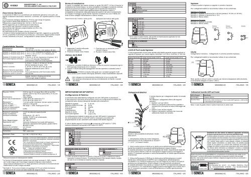
Uscita<br />
Collegamento in tensione - Collegamento in corrente (corrente impressa).<br />
Per i collegamenti elettrici si raccomanda l’utilizzo di cavo schermato.<br />
V / I +<br />
-<br />
5<br />
OUTPUT<br />
6<br />
7<br />
8<br />
POWER<br />
SUPPLY<br />
Nota: quando si utilizza l’uscita in corrente, per ridurre la dissipazione dello strumento,<br />
è conveniente collegare un carico > 250 Ù.<br />
R<br />
THE INTERNATIONAL CERTIFICATION NETWORK<br />
ISO9001-2000<br />
INPUT<br />
Indicazioni tramite LED sul fronte<br />
LED (Rosso) Significato<br />
Lampeggio Guasto interno.<br />
Acceso fisso<br />
INPUT<br />
1<br />
2<br />
3<br />
4<br />
1<br />
Tensione<br />
fino a 30 Vdc<br />
1<br />
2<br />
3<br />
4<br />
4<br />
Tensione<br />
fino a 10 Vdc<br />
Nota: in caso di guasto interno l’uscita rimarrà ad un valore nullo<br />
+<br />
V<br />
2<br />
4<br />
V<br />
Corrente<br />
Intervento della limitazione di fuori-scala dell’ingresso o dell’uscita<br />
o saturazione dell’ingresso.<br />
Smaltimento dei rifiuti elettrici ed elettronici (applicabile nell’Unione<br />
Europea e negli altri paesi con servizio di raccolta differenziata).<br />
Il simbolo presente sul prodotto o sulla sua confezione indica che il prodotto<br />
non verrà trattato come rifiuto domestico. Sarà invece consegnato al centro di<br />
raccolta autorizzato per il riciclo dei rifiuti elettrici ed elettronici. Assicurandovi<br />
che il prodotto venga smaltito in modo adeguato, eviterete un potenziale<br />
impatto negativo sull’ambiente e la salute umana, che potrebbe essere<br />
causato da una gestione non conforme dello smaltimento del prodotto. Il<br />
riciclaggio dei materiali contribuirà alla conservazione delle risorse naturali.<br />
Per ricevere ulteriori informazioni più dettagliate Vi invitiamo a contattare<br />
l’ufficio preposto nella Vostra città, il servizio per lo smaltimento dei rifiuti o il<br />
fornitore da cui avete acquistato il prodotto.<br />
+<br />
3<br />
4<br />
mA
EN<br />
<strong>K109UI</strong><br />
V - mA CONVERTER<br />
WITH 3-POINT GALVANIC INSULATION<br />
General Description<br />
The <strong>K109UI</strong> instrument is a V - mA converter with 3-point galvanic insulation designed<br />
for industrial standard voltage or current signals with passive input and active output.<br />
Analogue/digital conversion takes place at 14 bit on every input range.<br />
The instrument also provides the following functions:<br />
Rejection programmable for 50 or 60 Hz mains frequency.<br />
Additional reading stabilisation filter.<br />
Inversion of the input and inverted output scales<br />
Input Out-of-Range programmable to 2.5% or 5.0%<br />
SQRT function.<br />
Linearisation for horizontal cylindrical tanks.<br />
The module is also characterised by its extremely compact size, coupling to 35 mm DIN<br />
driver, power supply available by bus, quick fit couplings by spring-type terminals, 3point<br />
insulation, onsite configuration by DIP-switch.<br />
Technical Features<br />
Power supply :<br />
Consumption :<br />
Voltage input (max. 50 V) :<br />
Voltage input (max. 30 V) :<br />
Current input (max. 24 V) :<br />
Permissible max. Input Out-of-<br />
Range :<br />
Processing :<br />
ADC :<br />
19,2..30 Vdc<br />
Max 22 mA at 24 Vdc ( 20 mA output )<br />
0..15 V, 0..30 V, Input Impedance: 325 kÙ<br />
0..10 V, 2..10 V, 0..5 V, 1..5 V,<br />
Input Impedance: 110 kÙ<br />
0..20 mA, 4..20 mA, Input Impedance: 35 Ù<br />
± 2,5 or ± 5% depending on setting (see section on<br />
Input Out-of-Range Limits)<br />
Voltage output :<br />
0..5 Vdc, 1..5 Vdc, 0..10 Vdc and 10..0 Vdc<br />
Minima load resistance: 2 KÙ<br />
Current output :<br />
0..20 mA, 4..20 mA, 20..0 mA e 20..4 mA<br />
Maximum load resistance: 500 Ù<br />
Maximum applied Voltage : ± 30 V<br />
Permissible max. Output Out-of- Fixed (see section on Output Out-of-Range Limits)<br />
Range:<br />
Current output protection : approximately 25 mA<br />
Digital, 32 bit floating-point calculation<br />
14 bit on every input range<br />
MI000962-I/E ENGLISH - 1/8<br />
MI000962-I/E<br />
ENGLISH - 3/8<br />
MI000962-I/E ENGLISH - 5/8 MI000962-I/E<br />
ENGLISH - 7/8<br />
10-90% response : 50 Hz : max 41 ms without filter and 88 ms with filter;<br />
60 Hz : max 35 ms without filter and 74 ms with filter.<br />
Transmission :<br />
Digital Optical<br />
(1)<br />
Max. transmission error : 0.08% of the f.s. value for mA or 5 V output<br />
0.07% of the f.s. value for 10 V output<br />
(1)<br />
Resolution :<br />
1 mV for voltage output, 2 uA for current output<br />
Thermal drift :<br />
Lower than 120 ppm/K<br />
(2) (3)<br />
SQRT error :<br />
Linearisation error Cylindrical<br />
in the range 1..100%: floating point 32 bit<br />
(2)<br />
tank :<br />
0,05%<br />
Insulation Voltage :<br />
Protection Index :<br />
Operating Conditions :<br />
Storage Temperature :<br />
LED Signalling :<br />
Connections :<br />
Conductor Section :<br />
Wire stripping :<br />
Box : PBT (black colour)<br />
Dimensions, Weight :<br />
Standards :<br />
(1) No linearisation function connected<br />
1,5 KV (50 Hz for 1 min )<br />
IP20<br />
Temperature -20..+65 °C<br />
Humidity 30..90 % at 40°C (non-condensing)<br />
Altitudine 2000 slm<br />
-40..+85 °C<br />
Input or output out-of-range limiter device triggered or<br />
input saturation. Internal fault.<br />
Spring terminals<br />
2<br />
0,2..2,5 mm<br />
8 mm<br />
6,2 x 93,1 x 102,5 mm, 50 g.<br />
EN50081-2 (electromagnetic emission, industrial surroundings)<br />
EN50082-2 (electromagnetic immunity, industrial surroundings)<br />
EN61010-1 (safety)<br />
All the circuits must be provided with double insulation from the<br />
circuits under dangerous voltage. The power supply<br />
transformer must be built to compliance with EN60742:<br />
“Insulation transformers and Safety transformers”.<br />
Notes:<br />
- Use with copper conductor.<br />
- Use in Pollution Degree 2 Environment .<br />
- Power Supply must be Class 2.<br />
- When supplied by an Isolated Limited Voltage/Limited<br />
Current power supply a fuse rated max 2.5Ashall be<br />
installed in the field.<br />
(2)<br />
Linearisation functions operate only in the 0..100% rated range, whereas for the<br />
under-range and the over-range, the input signal is transferred without any alteration<br />
(G=1). Continuity and monotonic quality of transfer guaranteed throughout the entire<br />
range of measurement<br />
(3) In the 0..1% section, the curve is linear with gain G=10 in order to avoid overamplification<br />
of the noise in the initial section of the measurement range.<br />
Installation rules<br />
This module has been designed for assembly on a DIN 46277 rail. Assembly in vertical<br />
position is recommended in order to increase the module's ventilation, and no raceways or<br />
other objects that compromise aeration must be positioned in the vicinity.<br />
Do not position the module above equipment that generates heat; we recommend<br />
positioning the module in the lower part of the control panel or container compartment.<br />
We recommend rail-type assembly using the corresponding bus connector (Code K-BUS)<br />
that eliminates the need to connect the power supply to each module.<br />
Inserting the module in the rail Removing the module from the rail<br />
Range : -150..650 °C<br />
Load : RI < 500 / RV > 2 k<br />
Test Voltage : 1.5 kV, 50 Hz, 1 min<br />
Amb. Temp. : -20..+65 °C<br />
+<br />
5<br />
1<br />
- OUTPUT<br />
6<br />
2<br />
+<br />
INPUT<br />
7<br />
3<br />
-<br />
8<br />
4<br />
POWER<br />
SUPPLY<br />
1<br />
0<br />
SW1 SW2<br />
19.2..30 Vdc<br />
P < 500 mW<br />
V / I<br />
1 -Attach the module in the upper part of<br />
the rail.<br />
2 - Press the module downwards.<br />
Using the K-BUS connector<br />
<strong>K109UI</strong><br />
Range : -150..650 °C<br />
Load : RI < 500 / RV > 2 k<br />
Test Voltage : 1.5 kV, 50 Hz, 1 min<br />
Amb. Temp. : -20..+65 °C<br />
+<br />
5<br />
1<br />
- OUTPUT<br />
6<br />
2<br />
+<br />
INPUT<br />
7<br />
3<br />
-<br />
8<br />
4<br />
POWER<br />
SUPPLY<br />
1<br />
0<br />
SW1 SW2<br />
19.2..30 Vdc<br />
P < 500 mW<br />
V / I<br />
1 -Apply leverage using a screwdriver (as<br />
shown in the figure).<br />
2 - Rotate the module upwards.<br />
1 - Compose the K-BUS connectors as required in order to obtain the number of positions<br />
necessary (each K-BUS permits the insertion of no. 2 modules).<br />
2 - Insert the K-BUS connectors in the rail by positioning them on the upper side of the rail<br />
and then rotating them downwards.<br />
IMPORTANT: Pay particular attention to the position of the protrudent terminals of the<br />
K-BUS. The K-bus must be inserted in the guide with the protrudent terminals on the left<br />
(as shown in the figure) otherwise the modules are turned upside downs.<br />
- Never connect the power supply directly to the bus connector on the DIN<br />
rail.<br />
! - Never tap power supply from the bus connector either directly or by using<br />
the module's terminals.<br />
SETTING OF THE DIP-SWITCHES<br />
Factory setting<br />
All the module DIP switches are at pos. 0 as defaut configuration.<br />
This set correspond to the following configuration :<br />
Input signal<br />
50-60 Hz mains frequency rejection<br />
Input filter<br />
Inversion<br />
Linearisation<br />
Output signal<br />
Input Out-of-range<br />
0..20 mA<br />
50 Hz<br />
Present<br />
No<br />
None<br />
0..20 mA<br />
± 5% limit<br />
It is understood that this configuration is valid only with all the DIP switches at position 0.<br />
If also one Dip is moved, it is necessary to set all the other parameter as indicated on<br />
the following tables.<br />
Note: for all following tables<br />
The indication indicates that the DIP-switch is set in Position 1 (ON).<br />
No indication is provided when the DIP-switch is set in Position 0 (OFF).<br />
INPUT SIGNAL<br />
SW1 1 2 3<br />
0..20 mA<br />
4..20 mA<br />
0..10 Vdc<br />
2..10 Vdc<br />
1..5 Vdc<br />
0..5 Vdc<br />
0..30 Vdc<br />
0..15 Vdc<br />
50-60 Hz MAINS FREQUENCY REJECTION INPUT FILTER (*)<br />
SW1 4<br />
SW1 5<br />
60 Hz<br />
Present<br />
50 Hz<br />
Absent<br />
(*) The filter increases the rejection of the disturbance to the mains frequency, and<br />
stabilizes the reading reducing the measure noise. It is advised to hold it always<br />
inserted, but that the maximum speed of answer is not demanded.<br />
INVERSION<br />
SW1 6<br />
Present<br />
Absent<br />
<strong>K109UI</strong><br />
FUNCTION<br />
SW1 7 8<br />
Default<br />
None<br />
SQRT<br />
Tank<br />
OUTPUT SIGNAL<br />
SW2 1 2 3<br />
0..20 mA<br />
4..20 mA<br />
20..0 mA (5)<br />
20..4 mA (5)<br />
0..10 Vdc<br />
0..5 Vdc<br />
1..5 Vdc<br />
2..10 Vdc<br />
(5) These are inverse output ranges that are useful whenever the linearisation applied is<br />
incompatible with the inversion of the input.<br />
INPUT OUT-OF-RANGE<br />
SW2 4<br />
5%<br />
2.5%<br />
Input Out-of-Range Limits<br />
The Out-of-Range Limits provided in the following table are applied to the input signal,<br />
whereas the fixed limits are applied to the output signal: 0..21 mA, 0..5,25 Vdc, 0..10,5<br />
Vdc.<br />
Rated value Input Out-of-Range Limit ± 2,5 % Input Out-of-Range Limit ± 5 %<br />
20 mA 20,5 mA 21 mA<br />
4 mA 3,5 mA 3 mA<br />
0 mA 0 mA 0 mA<br />
30 Vdc 30,75 Vdc 31,5 Vdc<br />
15 Vdc 15,375 Vdc 15,75 Vdc<br />
10 Vdc 10,25 Vdc 10,5 Vdc<br />
5 Vdc<br />
5,125 Vdc<br />
5,25 Vdc<br />
1 Vdc<br />
0,875 Vdc<br />
0,75 Vdc<br />
2 Vdc<br />
1,75 Vdc<br />
1,5 Vdc<br />
0 Vdc<br />
0 Vdc<br />
0 Vdc<br />
Electrical Connections<br />
0,2..2,5 mm 2<br />
8 mm<br />
Power supply<br />
There are various ways to provide the K Series<br />
modules with power.<br />
1 - Direct power supply to the modules by<br />
connecting 24 Vdc power supply directly to<br />
Terminals 7 ( + ) and 8 ( - ) of each module.<br />
The module has been designed for spring-type terminal<br />
electrical connections.<br />
Proceed as follows to make the connections:<br />
1 - Strip the cables by 0.8 mm<br />
2 - Insert a screwdriver in the square hole and press it<br />
until the cable lock spring opens.<br />
3 - Insert the cable in the round hole.<br />
4 - Remove the screwdriver and make sure that the cable<br />
is tightly fastened in the terminal.<br />
This document is property of SENECA srl. Duplication and reprodution are forbidden, if not authorized.<br />
Contents of the present documentation refers to products and technologies described in it. All technical<br />
data contained in the document may be modified without prior notice Content of this documentation is<br />
subject to periodical revision.<br />
SENECA s.r.l.<br />
Via Germania, 34 - 35127 - Z.I. CAMIN - PADOVA - ITALY<br />
Tel. +39.049.8705355 - 8705359 - Fax +39.049.8706287<br />
e-mail: info@seneca.it - www.seneca.it<br />
MI000962-I/E ENGLISH - 2/8 MI000962-I/E<br />
ENGLISH - 4/8<br />
MI000962-I/E ENGLISH - 6/8 MI000962-I/E<br />
ENGLISH - 8/8<br />
+<br />
19.2..30 Vdc<br />
-<br />
5<br />
OUTPUT<br />
6<br />
7<br />
8<br />
POWER<br />
SUPPLY<br />
INPUT<br />
2 - Using the K-BUS connector accessory for the distribution of the power supply to the<br />
modules via bus connector, in this way eliminating the need to connect power supply to<br />
each module.<br />
The bus can be supplied from any of the modules; the total absorption of the bus must be<br />
less than 400 mA. Higher absorption values can damage the module. An appropriately<br />
sized fuse must be connected in series to the power supply.<br />
3 - Using the K-BUS connector accessory for the distribution of the power supply to the<br />
modules via bus connector and the K-SUPPLY accessory for the connection of the power<br />
supply.<br />
The K-SUPPLY accessory is a 6.2 mm wide module that contains a set of protections<br />
designed to protect the modules connected via bus against over-voltage loads.<br />
The bus connector can be provided with power using the K-SUPPLY module if the total<br />
absorption of the bus is less than 1.5 A. Higher absorption values can damage both the<br />
module and the bus. An appropriately sized fuse must be connected in series to the power<br />
supply.<br />
1<br />
2<br />
3<br />
4<br />
Input<br />
The module accepts a current or voltage input signal.<br />
The use of shield cables is recommended for the electronic connections.<br />
Voltage input<br />
Terminal 1: Voltage input up to 30 VDC (current carrying capacity 0..15 VDC and 0..30<br />
VDC).<br />
Terminal 2: Voltage input up to 10 V.<br />
Terminal 4: Return<br />
Current input<br />
Terminal 3: Current input.<br />
Terminal 4: Return<br />
5<br />
OUTPUT<br />
6<br />
7<br />
8<br />
POWER<br />
SUPPLY<br />
Output<br />
Voltage connection - Current connection (applied current)<br />
The use of shield cables is recommended for the electronic connections.<br />
V / I +<br />
-<br />
5<br />
OUTPUT<br />
6<br />
7<br />
INPUT<br />
1<br />
8<br />
POWER<br />
SUPPLY<br />
2<br />
3<br />
4<br />
R<br />
THE INTERNATIONAL CERTIFICATION NETWORK<br />
ISO9001-2000<br />
INPUT<br />
1<br />
Voltage<br />
max 30 Vdc<br />
1<br />
2<br />
3<br />
4<br />
4<br />
+<br />
V<br />
Voltage<br />
max 10 Vdc<br />
2<br />
4<br />
+<br />
V<br />
Current<br />
Note: in order to reduce the instrument's dissipation, we recommend either using the<br />
output for voltage or guaranteeing a load of > 250 n<br />
Ù to the curre t output.<br />
LED indications on the front<br />
LED (Red) Meaning<br />
Flashing Internal fault.<br />
Steady light Input or output out-of-range limiter device triggered or input<br />
saturation.<br />
Note: in case of internal fault, the output will stay at null value.<br />
Disposal of Electrical & Electronic Equipment (Applicable throughout<br />
the European Union and other European countries with separate<br />
collection programs)<br />
This symbol, found on your product or on its packaging, indicates that this<br />
product should not be treated as household waste when you wish to dispose of<br />
it. Instead, it should be handed over to an applicable collection point for the<br />
recycling of electrical and electronic equipment. By ensuring this product is<br />
disposed of correctly, you will help prevent potential negative consequences<br />
to the environment and human health, which could otherwise be caused by<br />
inappropriate disposal of this product. The recycling of materials will help to<br />
conserve natural resources. For more detailed information about the recycling<br />
of this product, please contact your local city office, waste disposal service or<br />
thè retail store where you purchased this product.<br />
3<br />
4<br />
mA
F<br />
<strong>K109UI</strong><br />
Description générale<br />
L'instrument <strong>K109UI</strong> est un convertisseur avec isolation galvanique à trois points, pour les<br />
signaux en tension ou en courant conformes à la norme industrielle, avec une entrée<br />
passive et une sortie active.<br />
La conversion analogique-numérique est à 14 bits sur chaque plage en entrée.<br />
Il dispose en outre des fonctionnalités suivantes :<br />
Réjection programmable pour 50 Hz ou 60 Hz de réseau<br />
Filtre supplémentaire pour stabiliser la lecture<br />
Inversion de l'entrée et échelles de sortie inverties<br />
Hors-échelle de l'entrée programmable à 2,5% ou 5%<br />
Extraction de racine<br />
Linéarisation pour réservoirs cylindriques horizontaux<br />
Le module a aussi les caractéristiques suivantes : encombrement réduit (6,2 mm),<br />
fixation sur guide DIN 35 mm, alimentation possible par bus, connexions rapides à l'aide<br />
de bornes à ressort, isolation trois points, possibilité de configuration sur site à l'aide de<br />
commutateurs DIP.<br />
Caractéristiques techniques<br />
Alimentation :<br />
Absorption:<br />
Entrée en tension (max 50 V):<br />
Entrée en tension (max 30 V):<br />
Entrée en Courant (max 24 V):<br />
Hors-échelle entrée admis:<br />
19,2..30 Vdc<br />
max 22 mA à 24 Vdc (avec sortie à 20 mA)<br />
0..15 V, 0..30 V, Impédance en entrée: 325 kÙ<br />
0..10 V, 2..10 V, 0..5 V, 1..5 V, Impédance en entrée:<br />
110 kÙ<br />
0..20 mA, 4..20 mA, Impédance en entrée: 35 Ù<br />
± 2,5 ou ± 5% selon la configuration<br />
(cf. section Limites Hors-échelle)<br />
Sortie en tension :<br />
0..5 Vdc, 1..5 Vdc, 0..10 Vdc et 2..10 Vdc<br />
Résistance minimale de charge 2 KÙ<br />
Sortie en courant :<br />
0..20 mA, 4..20 mA, 20..0 mA, 20..4 mA<br />
Résistance maximale de charge 500 Ù<br />
Maximum Hors-échelle admis : Fixe (cf. section Limites Hors-échelle)<br />
Protection de la sortie en<br />
courant :<br />
environ 25 mA<br />
Elaboration :<br />
Numérique, Calcul en point flottant 32 bits<br />
ADC :<br />
14 bits sur chaque plage d'entrée<br />
MI000962-F/D<br />
FRANÇAIS - 1/8<br />
Réponse 10-90% : À 50 Hz max 41 ms sans filtre et 88 ms avec filtre engagé;<br />
À 60 Hz maxi 35 ms sans filtre et 74 ms avec filtre engagé.<br />
Optique Numérique<br />
Transmission :<br />
0,08% du bas d'échelle pour sortie mAou 5 V<br />
(1)<br />
Erreur max de transmission : 0,07% du bas d'échelle pour sortie 10 V<br />
(1)<br />
Résolution :<br />
1 mV pour sortie en tension, 2Apour sortie en courant<br />
Dérive Thermique : Inférieure à 120 ppm/K<br />
(2) (3)<br />
Erreur sur SQRT : Dans la plage 1..100% point flottant 32 bits<br />
Erreur sur linéarisation<br />
(2)<br />
Réservoir Cylindrique : 0,05%<br />
Tension d'isolation :<br />
Degré de protection :<br />
Conditions ambiantes :<br />
Temp. de stockage :<br />
Signalisations par DEL :<br />
Connexions :<br />
Section des conducteurs :<br />
Dénudage des conducteurs:<br />
Boîtier : PBT noir<br />
Dimensions, Poids :<br />
Normes :<br />
(1)<br />
Aucune fonction de linéarisation engagée<br />
CONVERTISSEUR V - mA<br />
AVEC ISOLATION GALVANIQUE À TROIS POINTS<br />
1,5 kV entre chaque paire de portes.<br />
IP20<br />
Température -20..+65 °C<br />
Humidité 10..90 % sans condensation.<br />
Altitude : 2000 mètres<br />
-40..+85 °C<br />
Intervention limite hors-échelle de l'entrée ou de la sortie,<br />
saturation de l'entrée, panne interne.<br />
Bornes à ressort<br />
2<br />
0,2..2,5 mm<br />
8 mm<br />
6,2 x 93,1 x 102,5 mm, 46 g.<br />
EN61000-6-4/2002 (émission électromagnétique, milieu<br />
industriel) EN61000-6-2/2005 (immunité électromagnétique,<br />
milieu industriel) EN61010-1/2001 (sécurité)<br />
Tous les circuits doivent être isolés avec une double isolation<br />
des circuits sous tension dangereuse. Le transformateur<br />
d'alimentation doit être conforme à la norme EN60742 :<br />
“Transformateurs d'isolation et transformateurs de sécurité”.<br />
Notes: - Utilisation avec conducteur de cuivre.<br />
- Utilisation dans l'environnement du niveau 2 de pollution.<br />
- L'alimentation doit être en classe 2.<br />
- Si l'alimentation est fournie par une source limitée en<br />
tension / limitée en courant, il est nécessaire de prévoir un<br />
fusible de 2.5A sur la ligne.<br />
(2)<br />
Les fonctions de linéarisation n'agissent que dans la plage nominale 0..100%, alors<br />
qu'en cas de valeurs au-dessous ou au-dessus de la plage le signal d'entrée est transféré<br />
sans aucune altération (G=1). La continuité est garantie ainsi que la monotonicité du<br />
transfert sur toute la plage mesurable.<br />
(3) Dans la partie 0..1% la courbe est linéaire avec un gain G=10, pour éviter l'amplification<br />
excessive du bruit dans la partie initiale de la plage de mesure.<br />
Normes d'installation<br />
Le module est conçu pour être monté sur rail DIN 46277. Afin d'en favoriser l'aération, il<br />
est conseillé de le monter à la verticale, en évitant les moulures ou autres objets pouvant<br />
empêcher la circulation d'air.<br />
Éviter de poser le module sur des appareils qui dégagent de la chaleur ; il est conseillé de<br />
le placer en bas du tableau ou de l'armoire.<br />
Il est conseillé de le monter sur rail à l'aide du connecteur bus prévu à cet effet (code K-<br />
BUS) qui évite de devoir brancher l'alimentation sur chaque module.<br />
Montage du module dans le guide Extraction du module du guide<br />
Range : -150..650 °C<br />
Load : RI < 500 / RV > 2 k<br />
Test Voltage : 1.5 kV, 50 Hz, 1 min<br />
Amb. Temp. : -20..+65 °C<br />
+<br />
5<br />
1<br />
- OUTPUT<br />
6<br />
2<br />
+<br />
INPUT<br />
7<br />
3<br />
-<br />
8<br />
4<br />
POWER<br />
SUPPLY<br />
1<br />
0<br />
SW1 SW2<br />
19.2..30 Vdc<br />
P < 500 mW<br />
V / I<br />
1 - Accrocher le module dans la partie<br />
supérieure du guide<br />
2 - Pousser le module vers le bas<br />
Utilisation du K-BUS<br />
<strong>K109UI</strong><br />
Range : -150..650 °C<br />
Load : RI < 500 / RV > 2 k<br />
Test Voltage : 1.5 kV, 50 Hz, 1 min<br />
Amb. Temp. : -20..+65 °C<br />
+<br />
5<br />
1<br />
- OUTPUT<br />
6<br />
2<br />
+<br />
INPUT<br />
7<br />
3<br />
-<br />
8<br />
4<br />
POWER<br />
SUPPLY<br />
1<br />
0<br />
SW1 SW2<br />
19.2..30 Vdc<br />
P < 500 mW<br />
V / I<br />
1 - Faire levier avec un tournevis (comme<br />
indiqué sur la figure)<br />
2 - Pivoter le module vers le haut<br />
1 -Assembler les connecteurs K-BUS afin d'obtenir le nombre d'emplacements<br />
nécessaires (chaque K-BUS permet d'insérer 2 modules)<br />
2 - Placer les K-BUS dans le rail en les introduisant par le haut et les tourner vers le<br />
bas.<br />
IMPORTANT: Le K-BUS doit être inséré dans la guide avec les connecteurs tournés<br />
vers gauche (comme montré dans la figure), en cas contraire les modules<br />
résulteraient renversés.<br />
- Ne jamais brancher l'alimentation directement au bus sur le guide DIN.<br />
! - Ne pas prélever directement l'alimentation du bus, ni à l'aide des bornes des<br />
modules.<br />
COMMUTATEURS DIP<br />
Positions de Fabrique<br />
<strong>K109UI</strong><br />
MI000962-F/D FRANÇAIS - 3/8 MI000962-F/D FRANÇAIS - 5/8<br />
MI000962-F/D FRANÇAIS - 7/8<br />
Le convertisseur sort de la fabrique avec tous les commutateurs DIP en position OFF.<br />
Dans cette position le convertisseur charge à l’alimentation la configuration suivante (sauf<br />
differente indication sur le b oîtier ) :<br />
Signal d'Entrée<br />
Réjection 50/60 Hz de réseau<br />
Filtre d'entrée<br />
Inversion<br />
Linéarisation<br />
Signal de Sortie<br />
Hors-échelle Entrée<br />
0..20 mA<br />
50 Hz<br />
Engagé<br />
Non<br />
Aucune<br />
0..20 mA<br />
Limites ± 5%<br />
Cette configuration est valide seulement avec tous les commutateurs DIP en position OFF.<br />
S'il est déplacé même un seul commutateur DIP il est nécessaire de pourvoir à une<br />
complète configuration du convertisseur comme indiqué dans les tableaux suivants.<br />
Remarque: dans tous les tableaux suivants<br />
L’indication correspond au commutateur DIP sur ON;<br />
Aucune indication ne correspond au commutateur DIP sur OFF<br />
SIGNAL D'ENTRÉE<br />
SW1 1 2 3<br />
0..20 mA<br />
4..20 mA<br />
0..10 Vdc<br />
2..10 Vdc<br />
1..5 Vdc<br />
0..5 Vdc<br />
0..30 Vdc<br />
0..15 Vdc<br />
RÉJECTION (50/60 Hz) DE RÉSEAU<br />
FILTRE D'ENTRÉE (*)<br />
SW1 4<br />
SW1 5<br />
60 Hz<br />
Présent<br />
50 Hz<br />
Absent<br />
(*) Le filtre augmente la réjection des parasites à la fréquence du secteur et stabilise la<br />
lecture en réduisant les parasites de mesure. Nous conseillons de toujours laisser le<br />
filtre engagé, sauf si vous avez besoin d'une vitesse de réponse maximum.<br />
INVERSION<br />
SW1 6<br />
Présent<br />
Absent<br />
FONCTION<br />
SW1 7 8<br />
Défaut<br />
Aucune<br />
Racine carrée<br />
Réservoir<br />
SIGNAL DE SORTIE<br />
SW2 1 2 3<br />
0..20 mA<br />
4..20 mA<br />
20..0 mA (5)<br />
20..4 mA (5)<br />
0..10 Vdc<br />
0..5 Vdc<br />
1..5 Vdc<br />
2..10 Vdc<br />
(5) Il s'agit d'échelles de sortie inverses, utiles lorsque la linéarisation appliquée n'est pas<br />
compatible avec l'inversion de l'entrée.<br />
HORS-ÉCHELLE ENTRÉE<br />
SW2 4<br />
5%<br />
2.5%<br />
Limites hors-échelle<br />
Les limites programmables de hors-échelle indiquées dans le tableau suivant s'appliquent<br />
au signal d'entrée, les limites fixe s'appliquent à la sortie: 0..21 mA, 0..5,25 Vdc, 0..10,5<br />
Vdc.<br />
Valeur Nominale Limite de hors-échelle ± 2,5 % Limite de hors-échelle ± 5 %<br />
20 mA 20,5 mA 21 mA<br />
4 mA 3,5 mA 3 mA<br />
0 mA 0 mA 0 mA<br />
30 Vdc 30,75 Vdc 31,5 Vdc<br />
15 Vdc 15,375 Vdc 15,75 Vdc<br />
10 Vdc 10,25 Vdc 10,5 Vdc<br />
5 Vdc<br />
1 Vdc<br />
2 Vdc<br />
0 Vdc<br />
0,2..2,5 mm 2<br />
8 mm<br />
MI000962-F/D FRANÇAIS - 2/8 MI000962-F/D FRANÇAIS - 4/8 MI000962-F/D FRANÇAIS - 6/8<br />
MI000962-F/D FRANÇAIS - 8/8<br />
5,125 Vdc<br />
0,875 Vdc<br />
1,75 Vdc<br />
0 Vdc<br />
Branchements électriques<br />
Alimentation<br />
Les modules de la série K peuvent être alimentés<br />
de plusieurs façons.<br />
1 - Alimentation directe des modules en branchant<br />
directement l'alimentation en 24 Vcc aux bornes 7<br />
(+) et 8 (-) de chaque module.<br />
5,25 Vdc<br />
0,75 Vdc<br />
1,5 Vdc<br />
0 Vdc<br />
Le module dispose de bornes à ressort pour les<br />
branchements électriques.<br />
Pour procéder aux branchements, suivre les instructions<br />
suivantes :<br />
1 - Dénuder les câbles sur 0,8 mm<br />
2 - Placer un tournevis plat dans le trou carré et<br />
appuyer pour ouvrir le ressort de blocage du câble<br />
3 - Introduire le câble dans le trou rond<br />
4 - Enlever le tournevis et vérifier si le câble est fixé<br />
solidement à la borne.<br />
+<br />
19.2..30 Vdc<br />
-<br />
5<br />
OUTPUT<br />
6<br />
7<br />
8<br />
POWER<br />
SUPPLY<br />
INPUT<br />
2 - Utilisation de l'accessoire K-BUS pour distribuer l'alimentation aux modules à l'aide du<br />
bus en évitant de devoir brancher chaque module.<br />
Le bus peut être alimenté à partir de n'importe quel module, la consommation totale du bus<br />
doit être inférieure à 400 mA. Une consommation supérieure risque d'abîmer le module. Il<br />
est nécessaire de prévoir un fusible ayant des dimensions appropriées sur l'alimentation.<br />
3 - Utilisation de l'accessoire K-BUS pour distribuer l'alimentation aux modules à l'aide du<br />
bus et de l'accessoire K-SUPPLY pour le branchement de l'alimentation.<br />
K-SUPPLY est un module de 6,2 mm de large qui contient une série de protections pour<br />
sauvegarder les modules branchés au bus contre toute surtension éventuelle.<br />
Le bus peut être alimenté à partir d'un module K-SUPPLY si la consommation totale du bus<br />
est inférieure à 1,5A. Une consommation supérieure risque d'abîmer le module et le bus. Il<br />
est nécessaire de prévoir un fusible ayant des dimensions appropriées sur l'alimentation.<br />
1<br />
2<br />
3<br />
4<br />
Entrée<br />
Le module accepte en entrée un signal en courant ou en tension.<br />
Pour les branchements électriques nous vous recommandons d'utiliser des câbles<br />
blindés.<br />
Entrée en Tension<br />
Borne 1: Entrée en tension jusqu'à 30 Vdc (débits 0..15 Vdc et 0..30 Vdc).<br />
Borne 2: Entrée en tension jusqu'à 10 Vdc.<br />
Borne 4: Retour (Terre)<br />
Entrée en Courant<br />
Borne 3: Entrée en Courant<br />
Borne 4: Retour (Terre)<br />
5<br />
OUTPUT<br />
6<br />
7<br />
8<br />
POWER<br />
SUPPLY<br />
Sortie<br />
Branchement en tension - Branchement en courant (courant contraint).<br />
Pour les branchements électriques nous vous recommandons d'utiliser des câbles<br />
blindés.<br />
V / I +<br />
-<br />
5<br />
OUTPUT<br />
6<br />
7<br />
8<br />
POWER<br />
SUPPLY<br />
INPUT<br />
1<br />
2<br />
3<br />
4<br />
Remarque: afin de réduire la dissipation de l'instrument, il convient garantir une charge<br />
> 250 Ù à la sortie en courant.<br />
Indications par LED sur la partie frontale<br />
LED (Rouge) Significative<br />
Clignotante Panne interne.<br />
Allume fixement<br />
INPUT<br />
1<br />
2<br />
3<br />
4<br />
Tension<br />
jusqu'à 30 Vdc<br />
1<br />
4<br />
Tension<br />
jusqu'à 10 Vdc<br />
Remarque: en cas de panne interne la sortie restera sur une valeur nulle.<br />
+<br />
V<br />
2<br />
4<br />
+<br />
V<br />
Courant<br />
Intervention de la limite de hors-échelle de l'entrée ou de la sortie<br />
ou saturation de l'entrée.<br />
Disposition concernant les équipements électriques et électroniques (applicable dans l'Union<br />
Européenne et dans d'autres pays européens avec des systèmes de collecte séparés)<br />
Ce symbole sur le produit ou sur son emballage indique que ce produit ne sera pas traité comme perte<br />
ménagère.Au lieu de cela il sera remis au point de collecte dédié pour le recyclage de l'équipement électrique<br />
et électronique. En s'assurant que ce produit est trié et jeté correctement, vous contribuerez a empécher de<br />
potentielles consequences négatives pour l'environnement et la santé humaine, qui pourraient autrement<br />
étre provoquées par la manutention de rebut inadéquate de ce produit. La réutilisation des matériaux aidera à<br />
conserver les ressources naturelles. Pour des informations plus détaillées sur la réutilisation de ce produit,<br />
vous pouvez contacter votre mairie, la societé de collecte et tri des rebuts ou le magasin où vous avez acheté<br />
Ce document appartient à SENECA srl. La duplication et la reproduction non autorisées en sont<br />
interdites. Le sujet de la documentation qui suit correspond au produit et à la technologie qui y sont<br />
décrits. Le contenu peut être modifié et des données peuvent y être adjointes pour raisons techniques ou<br />
commerciales. Le contenu de cette documentation est révisé.<br />
R<br />
THE INTERNATIONAL CERTIFICATION NETWORK<br />
ISO9001-2000<br />
SENECA s.r.l.<br />
Via Germania, 34 - 35127 - Z.I. CAMIN - PADOVA - ITALY<br />
Tel. +39.049.8705355 - 8705359 - Fax +39.049.8706287<br />
e-mail: info@seneca.it - www.seneca.it<br />
3<br />
4<br />
mA
D<br />
<strong>K109UI</strong><br />
SPANNUNG/STROM-WANDLER<br />
MIT GALVANISCHER DREIPUNKTISOLIERUNG<br />
Allgemeine Beschreibung<br />
Das Gerät <strong>K109UI</strong> ist ein Wandler mit galvanischer Dreipunktisolierung, für nach<br />
Industriestandard übliche Spannungs- oder Stromsignale, mit passivem Eingang und<br />
aktivem Ausgang. Die Analog-Digital-Wandlung erfolgt mit einer Auflösung von 14 bit<br />
für jeden Eingangsbereich.<br />
Der Wandler weist außerdem noch folgende Funktionen auf:<br />
Programmierbare Störfrequenzunterdrückung für 50 oder 60 Hz Netzfrequenz<br />
Zuschaltbarer Filter für die Stabilisierung der Anzeige<br />
Invertierbarer Eingang und invertierte Ausgangsskalen<br />
Programmierbarer Overrange-Bereich (auf 2,5% oder 5%)<br />
Quadratwurzelermittlung<br />
Linearisierung für zylindrische, horizontale Tanks<br />
Die Eigenschaften des Wandlers sind die stark begrenzten Abmessungen (6,2 mm), die<br />
Verankerung auf DIN-Schiene zu 35 mm, die Möglichkeit der Speisung über Bus, die<br />
schnellen Anschlüsse über Federklemmen, die galvanische 3-Wege Trennung und die<br />
Konfigurierbarkeit vor Ort über DIP-Schalter.<br />
Technische Eigenschaften<br />
Spannungsversorgung : 19,2..30 Vdc<br />
Leistungsaufnahme :<br />
Max. 22 mAbei 24 Vdc (mit Stromausgang von 20 mA)<br />
Spannungseingang (max. 50 V) : 0..15 V, 0..30 V, Eingangsimpedanz: 325 kÙ<br />
Spannungseingang (max. 30 V) : 0..10 V, 2..10 V, 0..5 V, 1..5 V,<br />
Stromeingang (max. 24 V) :<br />
Zugelassener Eingangs-<br />
Overrange-Bereich :<br />
Ausgangsspannung :<br />
Ausgangsstrom :<br />
Zugelassene Overrange-<br />
Höchstgrenzwert :<br />
Strom Ausgangsschutz :<br />
Verarbeitung :<br />
ADC :<br />
Abmessungen, Gewicht :<br />
Normen :<br />
Eingangsimpedanz: 110 kÙ<br />
0..20 mA, 4..20 mA, Eingangsimpedanz: 35 Ù<br />
± 2,5 oder ± 5%, je nach Einstellung (siehe Abschnitt<br />
“Overrange-Grenzwerte“)<br />
0..5 Vdc, 1..5 Vdc, 0..10 Vdc und 10..0 Vdc<br />
Min. Lastwiderstand: 2 kÙ<br />
0..20 mA, 4..20 mA, 20..0 mAund 20..4 mA<br />
Max. Lastwiderstand: 500 Ù<br />
unverstellbar (siehe Abschnitt “Overrange-<br />
Grenzwerte”)<br />
annähernd 25 mA<br />
Digital, Bearbeitung im 32-Bit-Floating-Point-Format<br />
14 bit für jeden Eingangsbereich<br />
MI000962-F/D DEUTSCH - 1/8<br />
MI000962-F/D DEUTSCH - 3/8<br />
MI000962-F/D DEUTSCH - 5/8 MI000962-F/D DEUTSCH - 7/8<br />
Reaktionszeit (10-90%) : bei 50 Hz max. 41 ms ohne Filter und 88 ms mit Filter;<br />
bei 60 Hz max. 35 ms ohne Filter und 74 ms mit Filter.<br />
Übertragung :<br />
Optisch-digital<br />
(1)<br />
Übertragungsfehler max. : 0,08% des Vollausschlags für denAusgang mAoder 5 V<br />
0.07% des Vollausschlags für denAusgang 10 V<br />
(1)<br />
Auflösung :<br />
1 mV für den Spannungsausgang, 2 A<br />
für den<br />
Stromausgang<br />
Temperaturdrift :<br />
< 120 ppm/K<br />
(2) (3)<br />
Fehler bei der SQRT : Im Bereich von 1..100%: 32-bit-floating-point Format<br />
Fehler bei der Linearisierung 0,05%<br />
(2)<br />
des zylindrischen Tanks :<br />
Isolierungsspannung : 1,5 kV zwischen allen Portpaaren<br />
Schutzart:<br />
IP20<br />
Umgebungsbedingungen : Temperatur -20..+65 °C<br />
Luftfeuchtigkeit 30..90 %, nicht kondensierend<br />
Einsatzhöhe: bis 2000 m über dem Meeresspiegel<br />
Lagertemperatur : -40..+85 °C<br />
LED-Anzeigen :<br />
Begrenzung des Eingangs-oder Ausgangs-Overrange-<br />
Bereichs, Sättigung des Eingangs, interner Schaden.<br />
Anschlüsse :<br />
Federklemmen<br />
Leiterquerschnitt :<br />
2<br />
0,2..2,5 mm<br />
Abisolierung der Leiter : 8 mm<br />
Gehäuse : PBT (schwarze Farbe)<br />
6,2 x 93,1 x 102,5 mm, 50 g.<br />
(1)<br />
Keine Linearisierungsfunktion eingeschalten.<br />
EN61000-6-4/2002 (elektromagnetische Emission, industrielle<br />
Umgebung) EN61000-6-2/2005 (elektromagnetische<br />
Immunität, industrielle Umgebung) EN61010-1/2001<br />
(Sicherheit) Alle Schaltungen müssen mit doppelter Isolierung<br />
gegen Schaltungen mit gefährlicher Spannung isoliert werden.<br />
Der Speisungstransformator muss der Norm EN60742:<br />
“Isolierungstransformatoren und Sicherheitstransformatoren”<br />
entsprechen.<br />
Anmerkungen: - Benutzen mit Kupferleitung.<br />
- Benutzen in Verschmutzungsgrad 2 Umgebung.<br />
- Spannungsversorgung muß Klasse 2 sein.<br />
- Bei Verwendung eines galvanisch getrennten Netzteils,<br />
sollte eine Sicherung von 2.5Amax. davor installiert werden.<br />
(2)<br />
Die Linearisierungsfunktionen arbeiten nur im Nominalbereich von 0…100%, während<br />
im Underrange- und im Overrange-Bereich das Eingangssignal ohne jegliche<br />
Veränderung (G=1) übertragen wird. Die Kontinuität und die Gleichmäßigkeit der<br />
Übertragung sind im gesamten messbaren Bereich garantiert.<br />
(3)<br />
In der Strecke 0…1% ist die Kurve linear mit einem Gewinn von G=10, um überflüssige<br />
Rauschamplifikation im ersten Teil des Meßbereichs zu vermeiden.<br />
Anweisungen zur Installation<br />
Das Modul ist für die Montage auf Schienen nach DIN 46277 ausgelegt. Für eine bessere<br />
Belüftung des Moduls empfehlen wir die Montage in vertikaler Stellung sowie die<br />
Vermeidung der Positionierung in Kanälen oder von sonstigen Gegenständen, die eine<br />
Belüftung behindern.<br />
Vermeiden Sie die Installation des Moduls über Geräten, die Wärme erzeugen; wir<br />
empfehlen die Installation im unteren Bereich der Schalttafel oder des Gehäuses.<br />
Wir empfehlen die Montage auf der Schiene mit dem entsprechenden Anschlussbus<br />
(Bestellnr. K-BUS), der das Anschließen der Speisung an jedes einzelne Modul<br />
überflüssig macht.<br />
Montage des Moduls in der Schiene Entfernung des Moduls von der Schiene<br />
Range : -150..650 °C<br />
Load : RI < 500 / RV > 2 k<br />
Test Voltage : 1.5 kV, 50 Hz, 1 min<br />
Amb. Temp. : -20..+65 °C<br />
+<br />
5<br />
1<br />
- OUTPUT<br />
6<br />
2<br />
+<br />
INPUT<br />
7<br />
3<br />
-<br />
8<br />
4<br />
POWER<br />
SUPPLY<br />
1<br />
0<br />
SW1 SW2<br />
19.2..30 Vdc<br />
P < 500 mW<br />
V / I<br />
1 - Setzen Sie das Modul in den oberen<br />
Teil der Schiene ein<br />
2 - Drücken Sie das Modul nach unten<br />
Einsatz des K-BUS<br />
<strong>K109UI</strong><br />
Range : -150..650 °C<br />
Load : RI < 500 / RV > 2 k<br />
Test Voltage : 1.5 kV, 50 Hz, 1 min<br />
Amb. Temp. : -20..+65 °C<br />
+<br />
5<br />
1<br />
- OUTPUT<br />
6<br />
2<br />
+<br />
INPUT<br />
7<br />
3<br />
-<br />
8<br />
4<br />
POWER<br />
SUPPLY<br />
1<br />
0<br />
SW1 SW2<br />
19.2..30 Vdc<br />
P < 500 mW<br />
V / I<br />
1 - Hebeln Sie mit einem Schraubenzieher<br />
(wie auf der Abbildung gezeigt)<br />
2 - Drehen Sie das Modul nach oben<br />
1 - Setzen Sie die WK-BUS-Anschlüsse zusammen, um die erforderlicheAnzahl von<br />
Positionen zu erzielen (jeder WK-BUS gestattet dieAufnahme von 2 Modulen)<br />
2 - Setzen Sie den WK-BUS in die Schiene ein; setzen Sie ihn dazu auf der oberen<br />
Seite ein und drehen Sie ihn nach unten<br />
WICHTIG: Schenken Sie der Position der vorstehenden Klemmen der Busschiene eine<br />
erhöhte Aufmerksamkeit. Der K-Bus muss so in die DIN-Schiene gesetzt werden, so dass<br />
die vorstehenden Klemmen links liegen (wie im Bild), anderenfalls sind die Wandler<br />
kopfüber montiert.<br />
!<br />
- Schließen Sie nie die Speisung direkt am Bus der DIN-Schiene an.<br />
- Greifen Sie die Speisung weder direkt, noch über die Klemmen der Module ab.<br />
EINSTELLUNG DER DIP-SCHALTER<br />
Werkseinstellung<br />
Alle DIP-Schalter des Moduls befinden sich in der Position OFF als Standardkonfiguration.<br />
Die Einstellungen entsprechen den folgenden Werten:<br />
Eingangssignal<br />
Störfrequenzunterdrückung für 50 oder<br />
60 Hz Netzfrequenz<br />
Eingangsfilter<br />
Invertierungsmöglichkeit<br />
Linearisierung<br />
Ausgangssignal<br />
Eingangs-Overrange-Bereich<br />
0..20 mA<br />
50 Hz<br />
Zugeschalten<br />
Nein<br />
Nein<br />
0..20 mA<br />
Grenzwerte ± 5% limit<br />
Obige Einstellungen sind also nur gültig, wenn alle DIP-Schalter auf OFF stehen. Wird<br />
auch nur ein DIP-Schalter verändert, ist es erforderlich, alle anderen Parameter wie folgt<br />
neu einzustellen.<br />
MERKE: Für alle nachfolgenden Tabellen<br />
Die Angabe von zeigt an, dass der DIP-Schalter in Position ON steht (AN).<br />
Keine Angabe bedeutet, dass der DIP-Schalter in der Position OFF steht (AUS).<br />
EINGANGSSIGNAL<br />
SW1 1 2 3<br />
0..20 mA<br />
4..20 mA<br />
0..10 Vdc<br />
2..10 Vdc<br />
1..5 Vdc<br />
0..5 Vdc<br />
0..30 Vdc<br />
0..15 Vdc<br />
STÖRFREQUENZUNTERDRÜCKUNG FÜR<br />
50-60 Hz NETZFREQUENZ<br />
SW1 4<br />
60 Hz<br />
50 Hz<br />
EINGANGSFILTER (*)<br />
SW1 5<br />
Ja<br />
Nein<br />
(*) Der Filter erhöht die Störfrequenzunterdrückung und stabilisiert die Anzeige, indem<br />
er das Signalrauschen verringert. Daher ist es besser, den Filter immer zuzuschalten,<br />
außer in den Fällen in denen maximale Reaktionsgeschwindigkeit erfordert wird.<br />
INVERTIERUNGSMÖGLICHKEIT<br />
SW1 6<br />
Ja<br />
Nein<br />
<strong>K109UI</strong><br />
FUNKTION<br />
SW1 7 8<br />
Vorgabe<br />
Keine<br />
Quadratwurzel (SQRT)<br />
Tank<br />
AUSGANGSSIGNAL<br />
SW2 1 2 3<br />
0..20 mA<br />
4..20 mA<br />
20..0 mA (5)<br />
20..4 mA (5)<br />
0..10 Vdc<br />
0..5 Vdc<br />
1..5 Vdc<br />
2..10 Vdc<br />
(5) Es handelt sich um invertierte Ausgangsskalen. Diese sind dann besonders nützlich,<br />
wenn die angewandte Linearisierung mit der Eingangsinversion nicht kompatibel ist.<br />
EINGANGS-OVERRANGE-BEREICH<br />
SW2 4<br />
5%<br />
2.5%<br />
Overrange-Grenzwerte<br />
Die programmierbaren Overrange-Grenzwerte, die in der untenstehenden Tabelle<br />
angeführt sind, gelten für das Eingangssignal. Für das Ausgangssignal gelten folgende,<br />
unverstellbare Grenzwerte: 0..21 mA, 0..5,25 Vdc, 0..10,5 Vdc.<br />
Nominalwert Overrange-Grenzwert ± 2,5% Overrange-Grenzwert ± 5%<br />
20 mA 20,5 mA 21 mA<br />
4 mA 3,5 mA 3 mA<br />
0 mA 0 mA 0 mA<br />
30 Vdc 30,75 Vdc 31,5 Vdc<br />
15 Vdc 15,375 Vdc 15,75 Vdc<br />
10 Vdc 10,25 Vdc 10,5 Vdc<br />
5 Vdc<br />
1 Vdc<br />
2 Vdc<br />
0 Vdc<br />
0,2..2,5 mm 2<br />
8 mm<br />
MI000962-F/D DEUTSCH - 2/8 MI000962-F/D DEUTSCH - 4/8<br />
MI000962-F/D DEUTSCH - 6/8 MI000962-F/D DEUTSCH - 8/8<br />
5,125 Vdc<br />
0,875 Vdc<br />
1,75 Vdc<br />
0 Vdc<br />
Elektrische Verbindung<br />
Spannungsversorgung<br />
Es bestehen verschiedene Möglichkeiten für die<br />
Speisung der Module der Serie K.<br />
1 - Direkte Speisung der Module durch Anschluss<br />
der Speisung von 24 Vdc direkt an die Klemmen<br />
7 (+) und 8 (-) jedes einzelnen Moduls<br />
5,25 Vdc<br />
0,75 Vdc<br />
1,5 Vdc<br />
0 Vdc<br />
Das Modul besitzt Federklemmen für die elektrischen<br />
Anschlüsse.<br />
Nehmen Sie bei den Anschlüssen auf die folgenden<br />
Anweisungen Bezug:<br />
1 Entfernen Sie 0,8 cm der Isolierung am Ende der<br />
Kabel<br />
2 Führen Sie einen Schraubenzieher in die<br />
quadratische Öffnung ein und drücken Sie ihn, bis sich<br />
die Feder öffnet, die das Kabel blockiert<br />
3 Führen Sie das Kabel in die runde Öffnung ein<br />
4 Ziehen Sie den Schraubenzieher heraus und<br />
überprüfen Sie, ob das Kabel sicher in der Klemme<br />
befestigt ist.<br />
+<br />
19.2..30 Vdc<br />
-<br />
5<br />
OUTPUT<br />
6<br />
7<br />
8<br />
POWER<br />
SUPPLY<br />
INPUT<br />
2 - Verwendung des Zubehörartikels K-BUS für die Verteilung der Speisung an die Module<br />
über Bus, wodurch die Speisung jedes einzelnen Moduls überflüssig wird.<br />
Über den Bus können alle Module gespeist werden; die Gesamtleistungsaufnahme des<br />
Busses muss unter 400 mA liegen. Bei größeren Leistungsaufnahmen können die Module<br />
beschädigt werden. In die Speisung muss eine entsprechend bemessene Sicherung in<br />
Reihe eingesetzt werden.<br />
3 - Verwendung des Zubehörartikels K-BUS für die Distribution der Speisung der Module<br />
über Bus sowie des Zubehörartikels K-SUPPLY für denAnschluss an die Speisung.<br />
Das K-SUPPLY ist ein Modul mit einer Breite von 6,2 mm, das eine Reihe von<br />
Schutzschaltungen zum Schutz der über den Bus angeschlossenen Module gegen<br />
eventuelle Überspannungen aufweist.<br />
Der Bus kann über ein Modul K-SUPPLY gespeist werden, falls die<br />
Gesamtleistungsaufnahme des Busses unter 1,5 A liegt. Bei höheren<br />
Leistungsaufnahmen können das Modul oder der Bus beschädigt werden. In die Speisung<br />
muss eine entsprechend bemessene Sicherung in Reihe eingesetzt werden.<br />
1<br />
2<br />
3<br />
4<br />
Input<br />
Das Modul empfängt ein Eingangssignal in Strom oder Spannung.<br />
Wir empfehlen, für den elektrischenAnschluss abgeschirmte Kabel zu verwenden.<br />
Spannungseingang<br />
Klemme 1: Spannungseingang bis zu 30 Vdc (Belastbarkeit 0..15 Vdc und 0..30 Vdc).<br />
Klemme 2: Spannungseingang bis zu 10 V.<br />
Klemme 4: Rückkehr (GND)<br />
Stromeingang<br />
Klemme 3: Stromeingang<br />
Klemme 4: Rückkehr (GND)<br />
5<br />
OUTPUT<br />
6<br />
7<br />
8<br />
POWER<br />
SUPPLY<br />
Ausgang<br />
Spannungsanschluss - Stromanschluss (Fremdstrom).<br />
Wir empfehlen, für den elektrischenAnschluss abgeschirmte Kabel zu verwenden.<br />
V / I +<br />
-<br />
5<br />
OUTPUT<br />
6<br />
7<br />
INPUT<br />
1<br />
8<br />
POWER<br />
SUPPLY<br />
2<br />
3<br />
4<br />
INPUT<br />
1<br />
Spannung<br />
max 30 Vdc<br />
1<br />
2<br />
3<br />
4<br />
4<br />
+<br />
V<br />
Spannung<br />
max 10 Vdc<br />
Anmerkung: Zur Reduzierung der Dissipation des Instruments sollte der<br />
Spannungsausgang verwendet oder eine Last von > 250 Ù am Stromausgang garantiert werden.<br />
Anzeige mit LED auf der Front<br />
LED ( rot) Bedeutung<br />
Blinken<br />
Konstantes<br />
Leuchten<br />
2<br />
4<br />
+<br />
V<br />
Strom<br />
Interner Schaden<br />
Begrenzung des Eingangs- oder Ausgangs-Overrange-Bereichs<br />
oder Sättigung des Eingangs.<br />
Hinweis: Bei internem Schaden bleibt derAusgangswert null.<br />
Entsorgung von alten Elektro und Elektronikgeräten (gültig in der Europäischen Union und anderen<br />
europäischen Ländern mit separatem Sammelsystem)<br />
Dieses Symbol auf dem Produkt oder auf der Verpackung bedeutet, dass dieses Produkt nicht wie HausmuII<br />
behandelt werden darf. Stattdessen soll dieses Produkt zu dem geeigneten Entsorgungspunkt zum Recyclen<br />
von Elektro und Elektronikgeräten gebracht werden. Wird das Produkt korrekt entsorgt, helfen Sie mit,<br />
negativen Umwelteinflüssen und Gesundheitsschäden vorzubeugen, die durch unsachgemäße Entsorgung<br />
verursacht werden könnten. Das Recycling von Material wird unsere Naturressourcen erhalten. Für nähere<br />
Informationen über das Recyclen dieses Produktes kontaktieren Sie bitte Ihr lokales Bürgerbüro, Ihren<br />
HausmüllAbholservice oder das Geschäft, in dem Sie dieses Produkt gekauft haben.<br />
Dieses Dokument ist Eigentum der Fa. SENECA srl.. Das Kopieren und die Vervielfältigung sind ohne<br />
vorherige Genehmigung verboten. Inhalte der vorliegenden Dokumentation beziehen sich auf das dort<br />
beschriebene Gerät. Alle technischen Inhalte innerhalb dieses Dokuments können ohne vorherige<br />
Benachrichtigung modifiziert werden. Der Inhalt des Dokuments ist Inhalt einer wiederkehrenden Revision.<br />
R<br />
THE INTERNATIONAL CERTIFICATION NETWORK<br />
ISO9001-2000<br />
SENECA s.r.l.<br />
Via Germania, 34 - 35127 - Z.I. CAMIN - PADOVA - ITALY<br />
Tel. +39.049.8705355 - 8705359 - Fax +39.049.8706287<br />
e-mail: info@seneca.it - www.seneca.it<br />
3<br />
4<br />
mA