Nr. 6851 Anleitung zu Motoraufhängung für Motor ZDZ ... - Graupner
Nr. 6851 Anleitung zu Motoraufhängung für Motor ZDZ ... - Graupner
Nr. 6851 Anleitung zu Motoraufhängung für Motor ZDZ ... - Graupner

You also want an ePaper? Increase the reach of your titles
YUMPU automatically turns print PDFs into web optimized ePapers that Google loves.
<strong>zu</strong> Best.-<strong>Nr</strong>. <strong>6851</strong><br />
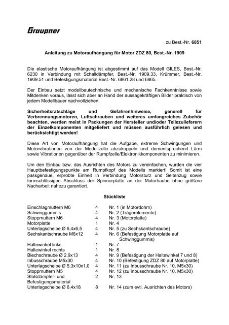
<strong>Anleitung</strong> <strong>zu</strong> <strong><strong>Motor</strong>aufhängung</strong> <strong>für</strong> <strong>Motor</strong> <strong>ZDZ</strong> 80, Best.-<strong>Nr</strong>. 1909<br />
Die elastische <strong><strong>Motor</strong>aufhängung</strong> ist abgestimmt auf das Modell GILES, Best.-<strong>Nr</strong>.<br />
6230 in Verbindung mit Schalldämpfer, Best.-<strong>Nr</strong>. 1909.33, Krümmer, Best.-<strong>Nr</strong>.<br />
1909.51 und Befestigungsmaterial Best.-<strong>Nr</strong>. 6861.28 und 6865.<br />
Der Einbau setzt modellbautechnische und mechanische Fachkenntnisse sowie<br />
Mitdenken voraus, lässt sich aber an Hand der aussagekräftigen Bilder praktisch von<br />
jedem Modellbauer nachvollziehen.<br />
Sicherheitsratschläge und Gefahrenhinweise, generell <strong>für</strong><br />
Verbrennungsmotoren, Luftschrauben und weiteres umfangreiches Zubehör<br />
beachten, werden meist in Packungen der Hersteller und/oder Teile<strong>zu</strong>lieferern<br />
der Einzelkomponenten mitgeliefert und müssen ausführlich gelesen und<br />
berücksichtigt werden!<br />
Diese Art von <strong><strong>Motor</strong>aufhängung</strong> hat die Aufgabe, extreme Schwingungen und<br />
<strong>Motor</strong>vibrationen von der Modellzelle ab<strong>zu</strong>koppeln und dementsprechend Lärm<br />
sowie Vibrationen gegenüber der Rumpfzelle/Elektronikkomponenten <strong>zu</strong> minimieren.<br />
Um den Einbau bzw. das Ausrichten des <strong>Motor</strong>s <strong>zu</strong> vereinfachen, wurden die vier<br />
Hauptbefestigungspunkte am Rumpfkopf des Modells markiert! Somit ist eine<br />
passgenaue, erprobte Einheit in Verbindung <strong>Motor</strong>sturz und Seiten<strong>zu</strong>g sowie<br />
formschlüssigen Abschluss der Spinnerplatte an der <strong>Motor</strong>haube ohne größere<br />
Nacharbeit nahe<strong>zu</strong> garantiert.<br />
Stückliste<br />
Einschlagmuttern M6 4 <strong>Nr</strong>. 1 (in <strong>Motor</strong>dohm)<br />
Schwinggummis 4 <strong>Nr</strong>. 2 (Trägerelemente)<br />
Stoppmuttern M6 4 <strong>Nr</strong>. 3 (<strong>Motor</strong>platte)<br />
<strong>Motor</strong>platte 1 <strong>Nr</strong>. 4<br />
Unterlagscheibe Ø 6,4x6,5 4 <strong>Nr</strong>. 5 (<strong>zu</strong> Sechskantschraube)<br />
Sechskantschraube M6x12 4 <strong>Nr</strong>. 6 (Befestigung <strong>Motor</strong>platte auf<br />
Schwinggummis)<br />
Haltewinkel links 1 <strong>Nr</strong>. 7<br />
Haltewinkel rechts 1 <strong>Nr</strong>. 8<br />
Blechschraube Ø 2,9x13 4 <strong>Nr</strong>. 9 (Befestigung der Haltewinkel 7 und 8)<br />
Inbusschraube M5x30 4 <strong>Nr</strong>. 10 (Befestigung <strong>ZDZ</strong> 80 auf <strong>Motor</strong>platte)<br />
Unterlagscheibe Ø 5,3x10x1,0 4 <strong>Nr</strong>. 11 (<strong>zu</strong> Inbusschraube <strong>Nr</strong>. 10, M5x30)<br />
Stoppmuttern M5 4 <strong>Nr</strong>. 12 (<strong>zu</strong> Inbusschraube <strong>Nr</strong>. 10, M5x30)<br />
Stoßdämpfer- und 2 <strong>Nr</strong>. 13<br />
Befestigungsmaterial<br />
Unterlagscheibe Ø 6,4x18 8 <strong>Nr</strong>. 14 (<strong>zu</strong>m evtl. Ausrichten des <strong>Motor</strong>s)
Einbauanleitung<br />
Die vier Markierungen am <strong>Motor</strong>spant von GILES, Best.-<strong>Nr</strong>. 6230, entsprechend dem<br />
Lochbild der <strong>Motor</strong>platte (4), an denen die Antriebseinheit/<strong>Motor</strong>platte (4) mit<br />
Schwinggummis (2) am Kopfspant des Rumpfes befestigt werden.<br />
• Die vier Markierungen am Kopfspant des Rumpfes GILES mit Ø 7,3 durchbohren,<br />
Einschlagmuttern (1) befestigen.<br />
• Stoßdämpfer (13) mit Befestigungsmaterial an den Haltewinkeln (7/8)/<strong>Motor</strong>platte<br />
(4) entsprechend den Abbildungen 3, 4, 5 befestigen – Haltewinkel (links) (7) und<br />
Haltewinkel (rechts) (8) nicht verwechseln. Ansicht und Form des linken und<br />
rechten Hebels in Bild 2 ersichtlich!<br />
• Die, wie oben beschrieben, vorkonfektionierte Einheit an <strong>Motor</strong>spant/Rumpfzelle<br />
befestigen – Schwinggummis (2) in Einschlagmuttern schrauben, <strong>Motor</strong>platte (4)<br />
mit Sechskantschrauben (6) und Unterlagscheiben (5) verbinden.<br />
• Lage und Position der Haltewinkel (7) und (8) ungefähr aus Bild 5 entnehmen.<br />
• Die Haltewinkel (7) und (8) werden mit den Blechschrauben (9) am<br />
<strong>Motor</strong>spant/Rumpfzelle verschraubt. Achtung: Bei Befestigung der Haltewinkel in<br />
Lage, wie in Bild 5 abgebildet, muss der Hub der Stoßdämpfer (13) berücksichtigt<br />
werden - Abstandsmaß 7,5 mm der Kolbenstange zwischen<br />
Stoßdämpfergehäuse und schwarzem Kugelkopf, wie in Bild 3, 4 und 5 gezeigt,<br />
einhalten – die Lage der Haltewinkel sollte so ungefähr der, die in Bild 5,<br />
entsprechen, aber unbedingt in Berücksichtigung des Abstandsmaßes von 7,5<br />
mm der Kolbenstange.<br />
• Sind Haltewinkel (7) und (8) wie beschrieben positioniert, so werden sie mit den<br />
Blechschrauben (9) befestigt.<br />
• <strong>Motor</strong> mit Befestigungsmaterial (10, 11, 12), wie in Bild 1 gezeigt, verschrauben.<br />
• Für Vergaser/Anlenkung und Abgaskrümmerrohr, Best.-<strong>Nr</strong>. 1909.51, muss ein<br />
entsprechend großer Durchbruch im <strong>Motor</strong>spant (4), am Rumpf ungefähr<br />
entsprechend der Größe der quadratischen Ausfräsung der <strong>Motor</strong>platte<br />
ausgearbeitet werden – in Betrieb darf keinesfalls der Vergaser oder<br />
Anlenkungsteile des Vergasers am <strong>Motor</strong>spant/Rumpfzelle anschlagen<br />
(Abgaskrümmer ebenfalls).<br />
• Ist die einsatzbereite <strong>Motor</strong>einheit komplett eingebaut, so sollte die<br />
Formschlüssigkeit dem Übergang der <strong>Motor</strong>haube Spinnerplatte entsprechen,<br />
eventuelle Ungenauigkeiten und Konturabweichungen der<br />
Spinnerplatte/gegenüber Anformung <strong>Motor</strong>haube mit Unterlagscheiben (14)<br />
ausgleichen.<br />
(<strong>Motor</strong>sturz und Seiten<strong>zu</strong>g sind am Modell GILES verbindlich, wurde<br />
erprobt/erflogen und konstruktiv beim Formenbau des Modells berücksichtigt –<br />
anlehnend der Anformungen, auch der Einbauanleitung, kann die <strong>Motor</strong>einheit,<br />
also nach dem Übergang Spinnerplatte/<strong>Motor</strong>haubenanformung, ausgerichtet und<br />
übernommen werden! (Bild 6).<br />
Bedingt durch das im Betrieb immer schwingende System, müssen<br />
selbstverständlich alle Schrauben ordentlich angezogen, evtl. auch <strong>zu</strong>sätzlich mit<br />
Schraubensicherungslack gesichert werden – nicht vergessen, die Schwinggummis<br />
(2) hinter der Einschlagmutter (1) mit Stoppmutter (3) sichern!
ACHTUNG:<br />
Vor dem ersten <strong>Motor</strong>lauf unbedingt kontrollieren, dass sämtliche Verschraubungen<br />
ordnungsgemäß befestigt wurden, insbesondere Verlängerung der Propellernabe,<br />
auch ordentliche Befestigung des Vergasers und sonstiger Anbauteile!<br />
Sicherheitsratschläge und Gefahrenhinweise, generell <strong>für</strong> Verbrennungsmotoren,<br />
Luftschrauben und weiteres umfangreiches Zubehör beachten, werden meist in<br />
Packungen der Hersteller und/oder Teile<strong>zu</strong>lieferern der Einzelkomponenten<br />
mitgeliefert und müssen ausführlich gelesen und berücksichtigt werden!<br />
GRAUPNER GmbH & Co. KG D-73230 KIRCHHEIM/TECK GERMANY<br />
Änderungen vorbehalten! Keine Haftung <strong>für</strong> Druckfehler! Id.-<strong>Nr</strong>. 48914 05/2003
to Order No. <strong>6851</strong><br />
Instructions for the engine mounting system for the <strong>ZDZ</strong> 80, Order No. 1909<br />
The shock-absorbing engine mount is designed for the GILES aerobatic model, Order No. 6230, in<br />
conjunction with the silencer, Order No. 1909.33, and exhaust manifold, Order No. 1909.51, together<br />
with the fixings, Order No. 6861.28 and 6865.<br />
Installation does require a certain level of modelling experience and mechanical skill, and a little<br />
imagination. Any modeller can complete the task with the help of the informative pictures.<br />
Information and recommendations regarding safety and hazards concerning internal<br />
combustion engines, propellers and other associated accessories are supplied by the<br />
manufacturer or supplier of the individual components. These are important and must be read<br />
carefully and observed.<br />
The purpose of this type of engine mounting system is to isolate extreme vibration and oscillations<br />
from the model’s airframe. The result is a marked reduction in the model’s noise level, and lower<br />
vibration transmitted to the airframe and electronic components.<br />
To simplify the installation and alignment of the engine the four mounting points (primary support<br />
points) are marked on the model’s firewall as standard. This virtually guarantees that the engine<br />
assembly fits correctly, that it is installed with the appropriate downthrust and sidethrust (as verified by<br />
our testing), and that the spinner backplate lines up correctly with the cowl, with only minimal<br />
adjustments required.<br />
Parts list<br />
Captive nuts, M6 4 No. 1 (in engine dome)<br />
Rubber buffers 4 No. 2 (suspension elements)<br />
Self-locking nuts, M6 4 No. 3 (for engine plate)<br />
Engine plate 1 No. 4<br />
Washers, 6.4 Ø x 12.5 4 No. 5 (for hex-head bolts)<br />
Hex-head bolts, M6 x 12 4 No. 6 (for securing engine plate / dampers)<br />
L.H. mounting bracket 1 No. 7<br />
R.H. mounting bracket 1 No. 8<br />
Self-tapping screws, 2.9 Ø x 13 4 No. 9 (for securing brackets 7 / 8)<br />
Socket-head cap screws, M5 x 30 4 No. 10 (for fixing <strong>ZDZ</strong> 80 to engine plate)<br />
Shakeproof washers, 5.3 Ø x 10 x 0.1 4 No. 11 (for M5x30 socket cap screws, No. 10)<br />
Self-locking nuts, M5 4 No. 12 (for M5x30 socket cap screws, No. 10)<br />
Shock absorbers and fixings 2 No. 13<br />
Washers, 6.4 Ø x 18 8 No. 14 (engine thrustline adjustment)
Installation instructions<br />
The four marked points on the firewall of the GILES, Order No. 6230, follow the pattern of the holes in<br />
the engine plate (4). The engine / engine plate (4) assembly is attached to the fuselage firewall at<br />
these points using the rubber buffers (2).<br />
• Drill 7.3 mm Ø holes in the firewall at the four marked points, and press the captive nuts (1) into<br />
them.<br />
• Screw the shock absorbers (No. 13) to the mounting brackets (7 / 8) / engine plate (4) using the<br />
fixings supplied, as shown in Figs. 3, 4 and 5; take care not to mix up the left-hand bracket (7)<br />
and the right-hand bracket (8). The shape of the left and right brackets is shown in Fig. 2.<br />
• The assembly prepared as described above can now be fixed to the firewall of the airframe:<br />
screw the rubber buffers (2) into the captive nuts and secure the engine plate (4) using the hexhead<br />
bolts (6) and washers (5).<br />
• The approximate position and orientation of the mounting brackets 7 and 8 is shown in Fig. 5.<br />
• The mounting brackets (7) and (8) have to be fixed to the firewall using the self-tapping screws<br />
(9). Caution: be sure to take into account the travel of the shock absorbers (13) when positioning<br />
and fixing the mounting brackets, as shown in Fig. 5 - the piston rod spacing between the shock<br />
absorber housing and the black ball-end bolt should be 7.5 mm; this is shown in Figs. 3, 4 and 5.<br />
The orientation of the mounting brackets should be approximately as shown in Fig. 5, taking into<br />
account the 7.5 mm clearance.<br />
• Once you are confident that the mounting brackets (7) and (8) are positioned correctly, they can<br />
be fixed in place using the self-tapping screws No. 9.<br />
• Install the engine using the fixings (10, 11 and 12) as shown in Fig. 1.<br />
• An opening has to be cut in the firewall (4) to provide clearance for the carburettor, throttle<br />
linkage and exhaust manifold pipe, Order No. 1909.51. The opening should be approximately the<br />
size and shape of the square hole in the engine plate. It must be large enough to ensure that<br />
neither the carburettor nor the throttle linkage can possibly foul or contact the airframe (the same<br />
applies to the exhaust manifold).<br />
• Once the complete engine assembly has been installed, the spinner backplate should line up<br />
accurately with the front of the engine cowl. If this is not the case, any discrepancy can be made<br />
good by fitting spacer washers (14).<br />
The correct engine downthrust and sidethrust are already built into the GILES, i.e. the settings<br />
were established at the test-flying stage, and are built into the moulded fuselage. You can<br />
therefore be confident that the engine assembly can be installed as described in the instructions,<br />
and the spinner backplate aligned with the engine cowl, without requiring further adjustment (Fig.<br />
6).<br />
The elasticity in the mounting system means that the system is constantly in motion when the engine<br />
is running, and this naturally requires that all screwed joints should be really tight to avoid the risk of<br />
them shaking loose. A drop of thread-lock fluid is also recommended. Don’t forget to fit the self-locking<br />
nuts (3) behind the captive nuts (1) to secure the rubber buffers.<br />
CAUTION:<br />
Before running the engine for the first time it is essential to check that all screwed joints are<br />
really tight and secure. This applies in particular to the propeller hub extension, but also to the<br />
carburettor and all other parts attached to the engine.<br />
Information and recommendations regarding safety and hazards concerning internal<br />
combustion engines, propellers and other associated accessories are supplied by the<br />
manufacturer or supplier of the individual components. These are important and must be read<br />
carefully and observed.<br />
GRAUPNER GmbH & Co. KG D-73230 KIRCHHEIM/TECK GERMANY<br />
We reserve the right to introduce modifications. No liability for printing errors. Ident No. 48914 05/2003
pour Réf. N°<strong>6851</strong><br />
Instructions pour le bâti-moteur du moteur <strong>ZDZ</strong> 80, Réf. N°1909<br />
Ce bâti-moteur suspendu est adapté pour le modèle GILES, Réf. N°6230, en liaison avec le<br />
silencieux, Réf. N°1909.33, le coude d'échappement Réf. N°1908.51 et le matériel de fixation<br />
Réf. N°6861.28 et 6865.<br />
Le montage exige des connaissances techniques en modélisme et en mécanique ainsi que<br />
de la réflexion, mais après la consultation des illustrations détaillées jointes, chaque<br />
modéliste pourra le réaliser correctement.<br />
Les conseils de sécurité et les avertissements de danger pour les moteurs<br />
thermiques, les hélices et les autres nombreux accessoires qui sont généralement<br />
joints dans les emballages des fabricants devront être attentivement lus et observés!<br />
Ce genre de bâti-moteur suspendu à pour but de désaccoupler les oscillations extrêmes et<br />
les vibrations du moteur de la cellule du modèle et de minimiser en conséquence le bruit<br />
ainsi que les vibrations vis-à-vis du fuselage et des éléments électroniques.<br />
Pour faciliter le montage et l'alignement du moteur, les quatre points de fixation ont été<br />
marqués sur le couple avant du fuselage du modèle GILES.<br />
Liste des pièces<br />
ID # 0048914<br />
Ecrous à pointes M6 4 N°1 (avec le moteur)<br />
Silent-blocs 4 N°2 (Elément-supports)<br />
Ecrous nylstop M6 4 N°3 (Fixation silent-blocs)<br />
Plaque-moteur 1 N°4<br />
Rondelles plates Ø 6,4x6,5 4 N°5 (Pour les vis BTR)<br />
Vis BTR M6x12 4 N°6 (Fixation plaque-moteur/silent-blocs)<br />
Equerre gauche 1 N°7<br />
Equerre droite 1 N°8<br />
Vis parker Ø 2,9x13 4 N°9 (Fixation des équerres 7 et 8)<br />
Vis BTR M5x30 4 N°10 (Fixation du <strong>ZDZ</strong> 80 sur la plaque-moteur)<br />
Rondelles plates Ø 5,3x10x1,0 4 N°11 (pour la vis BTR N°10, M5x30)<br />
Ecrous nylstop M5 4 N°12 (pour la vis BTR N°10, M5x30)<br />
Amortisseurs avec matériel de 2 N°13<br />
fixation<br />
Rondelles plates Ø 6,4x18 8 N°14 (pour un éventuel alignement du moteur)
Instructions de montage<br />
Les quatre marquages sur le couple-moteur du modèle GILES, Réf. N°6230 correspondent<br />
aux perçages de la plaque-moteur (4); l'ensemble du bâti avec es l silent-blocs ID # 0048914<br />
(2) sera fixé<br />
sur ce couple<br />
• Percer les quatre emplacements marqués sur le couple-moteur avec un foret de Ø<br />
7,3mm et fixer les écrous à pointes N°1.<br />
• Fixer les amortisseurs (13) sur les équerres (7/8) et sur la plaque-moteur avec le matériel<br />
de fixation, conformément aux illustrations 3, 4 et 5. Ne pas inter-changer les équerres<br />
gauche (7) et droite (8); la vue et la forme des pièces gauche et droite est visible sur<br />
l'illustration 2!<br />
• Fixer l'ensemble pré-confectionné comme décrit ci-dessus sur le couple-moteur du<br />
fuselage, visser les silent-blocs dans les écrous à pointes et relier la plaque-moteur (4)<br />
avec les vis BTR (6) et les rondelles plates (5).<br />
• Relever la position approximative des équerres (7) et (8) sur l'illustration (5).<br />
• Les équerres (7) et (8) seront fixées sur le couple-moteur avec les vis parker (9).<br />
Attention: La course des amortisseurs N°13 devra être prise en compte pour la position<br />
et la fixation des équerres; relever la cote d'écart de 7,5mm de la tige du piston entre le<br />
corps de l'amortisseur et la rotule noire, visible sur les illustrations 3, 4 et 5. La position<br />
des équerres devra être aux environs de celle représentée sur l'illustration 5, mais en<br />
tenant compte absolument de l'écart de 7,5mm de la tige du piston!<br />
• Les équerres (7) et (8) étant positionnées comme il a été décrit, les fixer avec les vis<br />
parker N°9.<br />
• Monter le moteur avec le matériel de fixation (10, 11, 12), comme représenté sur<br />
l'illustration 1.<br />
• Une ouverture devra être pratiquée dans le couple-moteur pour le passage de la<br />
tringlerie de gaz et du coude d'échappement, Réf. N°1909.51, d'une taille<br />
correspondante au fraisage carré dans la plaque-moteur. Durant le fonctionnement, le<br />
carburateur ou la tringlerie ne devront en aucun cas taper contre le couple-moteur (de<br />
même que le coude d'échappement).<br />
• Lorsque l'ensemble moteur en ordre de marche est complètement monté, toutes<br />
inégalités éventuelles dans le raccordement de l'embase du cône d'hélice avec le capot -<br />
moteur pourront être compensées avec les rondelles plates (14).<br />
Les angles piqueur et d'anticouple de l'axe de traction éprouvés en vol pour le modèle<br />
GILES ont été pris en compte. Un assemblage exact, ainsi qu'un raccordement<br />
harmonieux de l'embase du cône d'hélice avec le capot -moteur sont ainsi garantis!<br />
(illustration 6).<br />
Du fait que le système en fonctionnement est continuellement en oscillations, toute la<br />
boulonnerie devra naturellement être fermement bloquée, avec éventuellement une<br />
application de freine-filet. Ne pas oublier de bloquer les silent-blocs (2) derrière les écrous à<br />
pointes (1) avec les écrous nylstop (3)!<br />
ATTENTION:<br />
Avant le premier démarrage du moteur, vérifier absolument si l'ensemble de la<br />
boulonnerie a été correctement fixé, particulièrement le prolongateur du moyeu<br />
d'hélice de même que la fixation du carburateur et des autres pièces.<br />
GRAUPNER GmbH & Co. KG D-73230 KIRCHHEIM/TECK GERMANY<br />
Sous réserve de modifications! Nous ne sommes pas responsables d'éventuelles erreurs d'impression!<br />
05/2003