bauanleitung discus 2ct - Graupner
bauanleitung discus 2ct - Graupner
bauanleitung discus 2ct - Graupner

You also want an ePaper? Increase the reach of your titles
YUMPU automatically turns print PDFs into web optimized ePapers that Google loves.
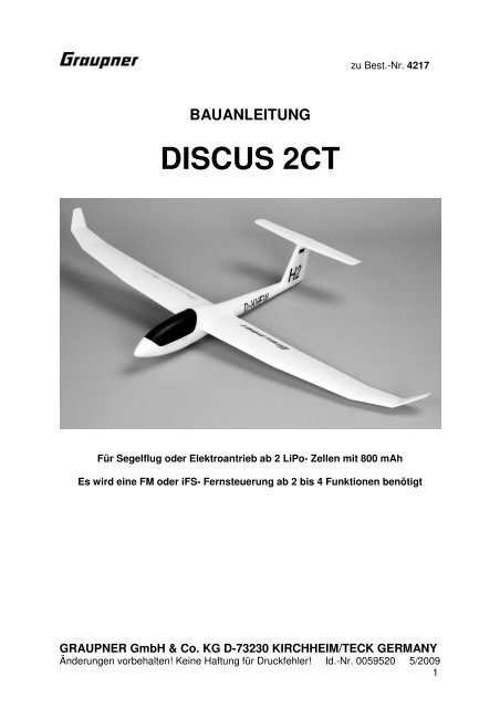
BAUANLEITUNG<br />
DISCUS 2CT<br />
zu Best.-Nr. 4217<br />
Für Segelflug oder Elektroantrieb ab 2 LiPo- Zellen mit 800 mAh<br />
Es wird eine FM oder iFS- Fernsteuerung ab 2 bis 4 Funktionen benötigt<br />
GRAUPNER GmbH & Co. KG D-73230 KIRCHHEIM/TECK GERMANY<br />
Änderungen vorbehalten! Keine Haftung für Druckfehler! Id.-Nr. 0059520 5/2009<br />
1
Bitte unbedingt die folgenden Sicherheitshinweise beachten.<br />
Sofern das Modell an eine andere Person weitergegeben wird, müssen diese<br />
Sicherheitshinweise, bzw. die komplette Bauanleitung zur Beachtung weitergegeben werden.<br />
Sicherheitshinweise<br />
Für den Betrieb Ihres Flugmodells benötigen Sie eine gültige Haftpflichtversicherung, dies ist<br />
vom Gesetzgeber so vorgeschrieben.<br />
Vor dem Versuch der ersten Inbetriebnahme muss die gesamte Betriebs- bzw. Bauanleitung<br />
sorgfältig gelesen werden. Sie alleine sind verantwortlich für den sicheren Betrieb Ihres RC-<br />
Flugmodells. Bei Jugendlichen muss der Bau und Betrieb von einem Erwachsenen, der mit den<br />
Gegebenheiten und möglichen Gefahren eines RC-Flugmodells vertraut ist, verantwortlich<br />
überwacht werden.<br />
Rechtlich gesehen, ist ein Flugmodell ein Luftfahrzeug und unterliegt entsprechenden<br />
Gesetzen, die unbedingt eingehalten werden müssen. Die Broschüre »Modellflugrecht,<br />
Paragrafen und mehr«, Best.-Nr. 8034.02 stellt eine Zusammenfassung dieser Gesetze dar; sie<br />
kann auch beim Fachhandel eingesehen werden. Ferner müssen postalische Auflagen für die<br />
Fernlenkanlage beachtet werden. Entsprechende Hinweise finden Sie in der<br />
Bedienungsanleitung Ihrer Fernsteueranlage.<br />
Es dürfen nur die in dem Bausatz enthaltenen Teile, sowie die ausdrücklich von uns<br />
empfohlenen Original-<strong>Graupner</strong>-Zubehör- und Ersatzteile verwendet werden. Wird eine<br />
Komponente der Antriebseinheit geändert, ist ein sicherer Betrieb nicht mehr gewährleistet<br />
und es erlischt jeglicher Garantieanspruch.<br />
Kurzschlüsse und Falschpolungen vermeiden.<br />
Durch die hohe Energie der Batterien besteht Explosions- und Brandgefahr.<br />
Ein RC-Flugmodell kann nur funktionsfähig sein und den Erwartungen entsprechen, wenn es<br />
im Sinne der Bauanleitung sorgfältigst gebaut wurde. Nur ein vorsichtiger und überlegter<br />
Umgang beim Betrieb schützt vor Personen- und Sachschäden. Niemand würde sich in ein<br />
Segelflugzeug setzen und - ohne vorausgegangene Schulung - versuchen, damit zu fliegen.<br />
Erfolgreiches Modellfliegen erfordert ebenso eine Ausbildungs-bzw. Übungsphase.<br />
Der Hersteller hat jedoch keine Möglichkeit, den Bau und den Betrieb eines RC-Flugmodells zu<br />
beeinflussen. Deshalb wird hiermit auf die Gefahren nachdrücklich hingewiesen und jede<br />
Haftung dafür abgelehnt.<br />
Bitte wenden Sie sich dazu an erfahrene Modellflieger, an Vereine oder Modellflugschulen.<br />
Ferner sei auf den Fachhandel und die einschlägige Fachpresse verwiesen. Am besten als<br />
Club-Mitglied auf zugelassenem Modellflugplatz fliegen.<br />
Klebstoffe enthalten Inhaltsstoffe, die unter Umständen gesundheitsschädlich sein können.<br />
Beachten Sie daher unbedingt auch die entsprechenden Hinweise und Warnungen der<br />
Hersteller.<br />
Der Betreiber muss im Besitz seiner vollen körperlichen und geistigen Fähigkeiten sein. Wie<br />
beim Autofahren, ist der Betrieb des Flugmodells unter Alkohol oder Drogeneinwirkung nicht<br />
erlaubt.<br />
Informieren Sie Passanten und Zuschauer vor der Inbetriebnahme über Gefahren, die von<br />
Ihrem Modell ausgehen und ermahnen Sie diese, sich in ausreichendem Schutzabstand<br />
aufzuhalten.<br />
Stets mit dem notwendigen Sicherheitsabstand zu Personen oder Hindernissen fliegen, nie<br />
Personen überfliegen oder auf sie zufliegen!<br />
Modellflug darf nur bei Außentemperaturen von - 5º C bis + 35º C betrieben werden. Extreme<br />
Temperaturen können zu Veränderungen der Batteriekapazität, der Werkstoffeigenschaften<br />
sowie z. B. zu mangelhaften Klebeverbindungen u.s.w. führen.<br />
GRAUPNER GmbH & Co. KG D-73230 KIRCHHEIM/TECK GERMANY<br />
Änderungen vorbehalten! Keine Haftung für Druckfehler! Id.-Nr. 0059520 5/2009<br />
2
Jeder Modellflieger hat sich so zu verhalten, dass die öffentliche Sicherheit, insbesondere<br />
andere Personen und Sachen, sowie der Ablauf des Modellflugbetriebs nicht gefährdet oder<br />
gestört wird.<br />
Das Flugmodell niemals in der Nähe von Hochspannungsleitungen, Industriegeländen, in<br />
Wohngebieten, öffentlichen Straßen, Schulhöfen oder Spielplätzen usw. fliegen lassen.<br />
Überprüfung vor dem Start<br />
Vor jedem Einsatz korrekte Funktion überprüfen. Dazu den Sender einschalten, ebenso den<br />
Empfänger. Senderantenne ausziehen, kontrollieren ob alle Ruder in Neutrallage stehen,<br />
einwandfrei funktionieren und seitenrichtig ausschlagen. Diese Überprüfung bei laufendem<br />
Motor wiederholen, während ein Helfer das Modell festhält.<br />
Beim erstmaligen Steuern eines Flugmodells ist es von Vorteil, wenn ein erfahrener Helfer bei<br />
der Überprüfung und den ersten Flügen zur Seite steht.<br />
Warnungen müssen unbedingt beachtet werden. Sie beziehen sich auf Dinge und Vorgänge,<br />
die bei einer Nichtbeachtung zu schweren - in Extremfällen tödlichen Verletzungen oder<br />
bleibenden Schäden führen können.<br />
Luftschrauben die durch einen Motor angetrieben werden, stellen eine ständige<br />
Verletzungsgefahr dar. Sie dürfen mit keinem Körperteil berührt werden! Eine schnell drehende<br />
Luftschraube kann z. B. einen Finger einschneiden!<br />
Sich niemals in oder vor der Drehebene von Luftschrauben aufhalten! Es könnte sich doch<br />
einmal ein Teil davon oder die komplette Luftschraube lösen und mit hoher Geschwindigkeit<br />
und viel Energie wegfliegen und Sie oder Dritte treffen. Dies kann u. U. zu schweren<br />
Verletzungen führen . Darauf achten, dass kein sonstiger Gegenstand mit einer laufenden<br />
Luftschraube in Berührung kommt!<br />
Die Blockierung der Luftschraube, durch irgendwelche Teile, muss ausgeschlossen sein.<br />
Überprüfen Sie vor jeder Inbetriebnahme das Modell und alle an ihm gekoppelten Teile (z. B.<br />
Luftschrauben, RC-Teile usw.) auf festen Sitz und mögliche Beschädigungen. Das Modell darf<br />
erst nach Beseitigung aller Mängel in Betrieb genommen werden.<br />
Vergewissern Sie sich, dass die verwendete Sender- Frequenz frei ist. Erst dann den Sender<br />
einschalten! Funkstörungen, verursacht durch Unbekannte, können stets ohne Vorwarnung<br />
auftreten! Das Modell ist dann steuerlos und unberechenbar! Fernlenkanlage nicht<br />
unbeaufsichtigt lassen, um ein Betätigen durch Dritte zu verhindern.<br />
Elektromotor nur einschalten, wenn nichts im Drehbereich der Luftschraube ist. Nicht<br />
versuchen, die laufende Luftschraube anzuhalten. Elektromotor mit Luftschraube nur im<br />
eingebauten Zustand betreiben.<br />
Die Fluglage des Modells muss während des gesamten Fluges immer eindeutig erkennbar sein,<br />
um immer ein sicheres Steuern und Ausweichen zu gewährleisten. Machen sich während des<br />
Fluges Funktionsbeeinträchtigungen/Störungen bemerkbar, muss aus Sicherheitsgründen<br />
sofort die Landung eingeleitet werden. Sie haben anderen Luftfahrzeugen stets auszuweichen.<br />
Start- und Landeflächen müssen frei von Personen und sonstigen Hindernissen sein.<br />
Immer auf vollgeladene Batterien achten, da sonst keine einwandfreie Funktion der RC-Anlage<br />
gewährleistet ist.<br />
Niemals heiß gewordene, defekte oder beschädigte Batterien verwenden. Es sind stets die<br />
Gebrauchsvorschriften des Batterieherstellers zu beachten.<br />
Vor jedem Flug eine Überprüfung der kompletten RC-Anlage, sowie des Flugmodells, auf volle<br />
Funktionstüchtigkeit und Reichweite durchführen.<br />
Dabei ist zu beachten, dass bei der Inbetriebnahme die Motorsteuerfunktion am Sender immer<br />
zuerst in AUS-Stellung gebracht wird. Danach Sender und dann erst Empfangsanlage<br />
GRAUPNER GmbH & Co. KG D-73230 KIRCHHEIM/TECK GERMANY<br />
Änderungen vorbehalten! Keine Haftung für Druckfehler! Id.-Nr. 0059520 5/2009<br />
3
einschalten, um ein unkontrolliertes Anlaufen des Elektromotors zu vermeiden. Gleichfalls gilt<br />
immer zuerst Empfangsanlage ausschalten, danach erst den Sender.<br />
Überprüfen Sie, dass die Ruder sich entsprechend der Steuerknüppelbetätigung bewegen.<br />
Nach Gebrauch die Batterie aus dem Modell nehmen und nur im entladenen Zustand für Kinder<br />
unzugänglich, bei ca. + 5º bis + 25º C aufbewahren.<br />
Mit diesen Hinweisen soll auf die vielfältigen Gefahren hingewiesen werden, die durch<br />
unsachgemäße und verantwortungslose Handhabung entstehen können. Richtig und<br />
gewissenhaft betrieben ist Modellflug eine kreative, lehrreiche und erholsame<br />
Freizeitgestaltung.<br />
Herstellererklärung:<br />
Sollten sich Mängel an Material oder Verarbeitung an einem von uns in der Bundesrepublik<br />
Deutschland vertriebenen, durch einen Verbraucher (§ 13 BGB) erworbenen Gegenstand<br />
zeigen, übernehmen wir, die Fa. <strong>Graupner</strong> GmbH & Co KG, D-73230 Kirchheim/Teck im<br />
nachstehenden Umfang die Mängelbeseitigung für den Gegenstand.<br />
Rechte aus dieser Herstellererklärung kann der Verbraucher nicht geltend machen, wenn die<br />
Beeinträchtigung der Brauchbarkeit des Gegenstandes auf natürlicher Abnutzung, Einsatz<br />
unter Wettbewerbsbedingungen, unsachgemäßer Verwendung (einschließlich Einbau) oder<br />
Einwirkung von außen beruht.<br />
Diese Herstellererklärung lässt die gesetzlichen oder vertraglich eingeräumten<br />
Mängelansprüche und –rechte des Verbrauchers aus dem Kaufvertrag gegenüber seinem<br />
Verkäufer (Händler) unberührt.<br />
Umfang der Garantieleistung<br />
Im Garantiefall leisten wir nach unserer Wahl Reparatur oder Ersatz der mangelbehafteten<br />
Ware. Weitergehende Ansprüche, insbesondere Ansprüche auf Erstattung von Kosten im<br />
Zusammenhang mit dem Mangel (z.B. Ein-/Ausbaukosten) und der Ersatz von Folgeschäden<br />
sind – soweit gesetzlich zugelassen – ausgeschlossen. Ansprüche aus gesetzlichen<br />
Regelungen, insbesondere nach dem Produkthaftungsgesetz, werden hierdurch nicht berührt.<br />
Voraussetzung der Garantieleistung<br />
Der Käufer hat den Garantieanspruch schriftlich unter Beifügung des Originals des Kaufbelegs<br />
(z.B. Rechnung, Quittung, Lieferschein) und dieser Garantiekarte geltend zu machen. Er hat<br />
zudem die defekte Ware auf seine Kosten an die o.g. Adresse einzusenden.<br />
Der Käufer soll dabei den Material- oder Verarbeitungsfehler oder die Symptome des Fehlers<br />
so konkret benennen, dass eine Überprüfung unserer Garantiepflicht möglich wird.<br />
Der Transport des Gegenstandes vom Verbraucher zu uns als auch der Rücktransport erfolgen<br />
auf Gefahr des Verbrauchers.<br />
Gültigkeitsdauer<br />
Diese Erklärung ist nur für während der Anspruchsfrist bei uns geltend gemachten Ansprüche<br />
aus dieser Erklärung gültig. Die Anspruchsfrist beträgt 24 Monate ab Kauf des Gerätes durch<br />
den Verbraucher bei einem Händler in der Bundesrepublik Deutschland (Kaufdatum). Werden<br />
Mängel nach Ablauf der Anspruchsfrist angezeigt oder die zur Geltendmachung von Mängeln<br />
nach dieser Erklärung geforderten Nachweise oder Dokumente erst nach Ablauf der<br />
Anspruchsfrist vorgelegt, so stehen dem Käufer keine Rechte oder Ansprüche aus dieser<br />
Erklärung zu.<br />
Verjährung<br />
Soweit wir einen innerhalb der Anspruchsfrist ordnungsgemäß geltend gemachten Anspruch<br />
aus dieser Erklärung nicht anerkennen, verjähren sämtliche Ansprüche aus dieser Erklärung in<br />
6 Monaten vom Zeitpunkt der Geltendmachung an, jedoch nicht vor Ende der Anspruchsfrist.<br />
Anwendbares Recht<br />
Auf diese Erklärung und die sich daraus ergebenden Ansprüche, Rechte und Pflichten findet<br />
ausschließlich das materielle deutsche Recht ohne die Normen des Internationalen<br />
Privatrechts sowie unter Ausschluss des UN-Kaufrechts Anwendung.<br />
GRAUPNER GmbH & Co. KG D-73230 KIRCHHEIM/TECK GERMANY<br />
Änderungen vorbehalten! Keine Haftung für Druckfehler! Id.-Nr. 0059520 5/2009<br />
4
Allgemeines<br />
Das Modell DISCUS 2CT ist ein vorbildähnliches RC- Flugmodell, das hervorragende<br />
Flugleistungen erzielt. Bitte beachten Sie, dass das Modell in drei Versionen gebaut<br />
werden kann. Für jede Version sind unterschiedliche Zubehörteile erforderlich.<br />
Entscheiden Sie sich vor Baubeginn für eine Version, da ein nachträglicher Umbau<br />
nicht mehr möglich ist. Aus Sicherheitsgründen darf das Fluggewicht nicht über 500 g<br />
liegen.<br />
1. Segelversion<br />
2. Segelversion für F- Schlepp<br />
3. Elektroversion*<br />
* Diese Version ist besonders empfehlenswert, da der Motoraufsatz in Sekundenschnelle abgezogen werden kann und<br />
das Modell dann auch als reines Segelflugmodell eingesetzt werden kann.<br />
RC-Zubehör (nicht enthalten)<br />
Zur Steuerung des Modells sind FM-Fernsteueranlagen wie z. B. MX-12 bis MC-24<br />
bzw. iFS- Fernsteuersysteme geeignet. Weitere Informationen über RC-Zubehörteile<br />
sind dem GRAUPNER Hauptkatalog FS zu entnehmen<br />
FM Fernlenkset MX-12 FM 35* Best.-Nr. 4722<br />
*Frequenzband 35 MHz in Deutschland ausschließlich für Flugmodelle reserviert.<br />
Senderladekabel Best.-Nr. 3022<br />
Empfängerladekabel (nur für Segelversionen) Best.-Nr. 3021<br />
Ladekabel mit BEC Stecker (nur für Elektroversion) Best.-Nr. 3037<br />
Ladegerät ULTRAMAT 8 Best.-Nr. 6411<br />
Servo C131 (2 Stück erforderlich) Best.-Nr. 7121<br />
Trimmgewicht Best.-Nr. 536<br />
Zubehör für Segelversionen (nicht enthalten)<br />
Schleppkupplung Empfängerbatterie<br />
Best.-Nr. Best.-Nr.<br />
Innen Ø 6mm GRAUPNER<br />
7890.1 4N-600 AA 4,8 V/0,6 Ah 2585<br />
Zubehör für Elektroversion (nicht enthalten)<br />
Motoraufsatz<br />
Best.-Nr.<br />
SPEED 300 7,2V<br />
9401.22<br />
Antriebsbatterie<br />
Best.-Nr.<br />
GRAUPNER<br />
2 LiPo 800 7,4 V/0,8 Ah 7621.2BEC<br />
Servo für Schleppkupplung<br />
Best.-Nr.<br />
C 131<br />
7121<br />
Drehzahlregler<br />
Best.-Nr.<br />
PICO 8 BEC<br />
7171<br />
Erforderliche Werkzeuge und Klebstoffe (nicht enthalten)<br />
Balsamesser Best.-Nr. 980<br />
Sekundenkleber Best.-Nr. 5821<br />
Aktivator für Sekundenkleber Best.-Nr. 953.150<br />
Lötgerät 220 V (nur für Elektroversion) Best.-Nr. 826<br />
Radio-Lötzinn (nur für Elektroversion) Best.-Nr. 1176.1<br />
Weiterhin wird benötigt: Seitenschneider, Flachzange, Papierschere,<br />
Schraubendreher, Klebeband.<br />
GRAUPNER GmbH & Co. KG D-73230 KIRCHHEIM/TECK GERMANY<br />
Änderungen vorbehalten! Keine Haftung für Druckfehler! Id.-Nr. 0059520 5/2009<br />
5
Bauanleitung<br />
Bitte lesen Sie vor Baubeginn die Bauanleitung durch, sodass Sie einen Überblick<br />
über den Ablauf des Zusammenbaus erhalten. Legen Sie sich die jeweils<br />
notwendigen Bauteile, Werkzeuge und Klebstoffe für eine Baustufe bereit. Beim<br />
Zusammenbau immer auf eine saubere, glatte Unterlage achten oder auf einer<br />
Schaumstoffunterlage arbeiten. Sofern nichts anderes angegeben ist,<br />
Sekundenkleber mit Aktivator als Klebstoff verwenden. Am besten eine Seite der<br />
Klebeverbindung mit Klebstoff versehen und die Gegenseite mit Aktivator besprühen.<br />
Besonders darauf achten, dass kein Restklebstoff an Ihre Hände oder auf die<br />
Oberfläche des Modells gelangt. Überschüssigen Klebstoff sofort mit Zellstoffpapier<br />
abwischen.<br />
Achtung: Sekundenklebstoff darf keinesfalls mit Körperteilen in Verbindung<br />
kommen oder in Ihre Augen gelangen. Wir empfehlen deshalb bei der<br />
Anwendung Schutzhandschuhe und eine Schutzbrille zu tragen. Die Werkstatt<br />
mit Frischluft belüften. Den Klebstoff für Kinder unerreichbar aufbewahren.<br />
Verwenden Sie keinesfalls Styropor-Sekundenklebstoff, Holz-Weißleim oder<br />
Epoxyd- Klebstoff. Mit diesen Klebstoffen wird zwischen allen Materialien und<br />
dem SOLIDPOR®- Hartschaum keine feste Klebeverbindung erzielt.<br />
Rumpf mit Leitwerk und Kabinenhaube<br />
Die Rumpfverstärkung (3) in die rechte Rumpfseite (1) einkleben, dann gemeinsam<br />
die Bowdenzugaußenrohre (4/5), darauf achten, dass diese vorne 10 mm<br />
überstehen. Teil (6) nicht einkleben, wenn Sie die Segelversion mit Schleppkupplung<br />
wünschen.<br />
Die überflüssigen Hebel der Servosteuerkreuze abtrennen und die Servos per<br />
Servotester oder RC- Anlage neutral einstellen.<br />
GRAUPNER GmbH & Co. KG D-73230 KIRCHHEIM/TECK GERMANY<br />
Änderungen vorbehalten! Keine Haftung für Druckfehler! Id.-Nr. 0059520 5/2009<br />
6
Die Abbildung zeigt die fertig installierten Servos C131. Die Ruderzüge (18) und (20)<br />
in die Servos einhängen und einschieben, dann die beiden Servos in das<br />
Rumpfseitenteil einsetzen, nach vorne drücken und mit je zwei Tropfen<br />
Sekundenklebstoff sichern. Achtung, keinesfalls dünnflüssigen oder zuviel<br />
Sekundenklebstoff verwenden, da dieser sonst in die Servos gelangt und diese<br />
blockiert.<br />
Die Abbildung zeigt die eingeklebte Schleppkupplung bei Version 2. Die<br />
Rumpfnasenverstärkung (6) wird bei dieser Version nicht benötigt.<br />
Die Abbildung zeigt das Öffnen der Rumpfoberseite für die Trägerbasishälften (26)<br />
GRAUPNER GmbH & Co. KG D-73230 KIRCHHEIM/TECK GERMANY<br />
Änderungen vorbehalten! Keine Haftung für Druckfehler! Id.-Nr. 0059520 5/2009<br />
7
und (27). Diesen und den folgenden Arbeitsvorgang nur bei Elektroversion 3<br />
ausführen.<br />
Achtung, zuerst das BEC-Zuleitungskabel (enthalten bei Best.-Nr. 9401.22)<br />
kürzen und in die noch nicht eingeklebten Goldbuchsen (enthalten bei Best.-Nr.<br />
9401.22) einlöten. Die Goldbuchsen in Teil (26) einkleben, darauf achten, dass kein<br />
Klebstoff in die Buchsen gelangt. Dann die Trägerbasisteile in den vorbereiteten<br />
Rumpf einkleben. Das BEC-Kabel ebenfalls mit Klebstoff sichern.<br />
Die Abbildung zeigt die zum Verkleben vorbereiteten Rumpfseitenteile. Achtung,<br />
dieser Arbeitsvorgang erfordert eine hohe Konzentration. Unbedingt darauf<br />
achten, dass kein Klebstoff in die Ruderzüge gelangt. Zellstoffpapier bereitlegen<br />
um nötigenfalls überschüssigen Klebstoff abzuwischen.<br />
Das Seitenruder durch mehrfaches Biegen leichtgängig machen. Das Ruderhorn<br />
probeweise einsetzen, den Ruderzug (18) exakt passend abwinkeln und abtrennen.<br />
GRAUPNER GmbH & Co. KG D-73230 KIRCHHEIM/TECK GERMANY<br />
Änderungen vorbehalten! Keine Haftung für Druckfehler! Id.-Nr. 0059520 5/2009<br />
8
Das Ruderhorn einhängen und einkleben. Tipp: Sofern Sie noch wenig<br />
Flugerfahrung besitzen, außen einhängen, wie abgebildet. Wird ein möglichst großer<br />
Ruderausschlag gewünscht, in der mittleren Bohrung einhängen.<br />
Das Höhenruder vom Höhenleitwerk (12) so lange bis zum Anschlag auf und ab<br />
biegen, bis das Ruder sich leichtgängig bewegen lässt. Das Höhenleitwerk exakt<br />
ausgerichtet auf den Rumpf kleben. Durch Anvisieren von vorne und oben<br />
überprüfen.<br />
Das Anschließen und Einkleben des Höhenruderhornes (21) nach dem gleichen<br />
Prinzip wie bei dem Seitenruderhorn durchführen.<br />
Tipp: Sofern das Höhenruderscharnier zu schwergängig ist, dieses an den auf der<br />
Abbildung schwarz markierten Bereichen durchtrennen.<br />
GRAUPNER GmbH & Co. KG D-73230 KIRCHHEIM/TECK GERMANY<br />
Änderungen vorbehalten! Keine Haftung für Druckfehler! Id.-Nr. 0059520 5/2009<br />
9
Die Abbildung zeigt die Kabinenhaube (13) mit den Befestigungselementen (14) bis<br />
(17). Die Teile (14) und (17) an die Kabinenhaube kleben, die Teile (15) und (16) in<br />
den Rumpf einkleben. Siehe Baustadienfoto „RC- Installation“. Nötigenfalls, wie auf<br />
dem Foto erkennbar, eine Aussparung für die Servostecker mit dem Balsamesser<br />
heraustrennen.<br />
Die Abbildung zeigt die Einzelteile des Radkastens. Beim Verkleben darauf achten,<br />
dass kein Klebstoff in das Radlager gelangt.<br />
Der fertig in den Rumpf eingeklebte Radkasten.<br />
Die Tragfläche<br />
GRAUPNER GmbH & Co. KG D-73230 KIRCHHEIM/TECK GERMANY<br />
Änderungen vorbehalten! Keine Haftung für Druckfehler! Id.-Nr. 0059520 5/2009<br />
10
Den Holm (29) einkleben, die Nut mit Klebeband überkleben.<br />
Die fertige Tragfläche seitlich in den Rumpf einschieben.<br />
Die RC-Installation<br />
Die Abbildung zeigt die Installation der LiPo-Batterie und des Empfängers der<br />
Elektroversion 3. Der PICO 8 Drehzahlregler ist unter dem Empfänger angeordnet.<br />
Mit dem Schließen der BEC-Steckerverbindung, wie auf dem Foto zu sehen, wird die<br />
RC-Anlage eingeschaltet. Wird bei der Elektroversion der Motoraufsatz abgezogen<br />
dient die LiPo-Batterie als Empfängerbatterie. Das BEC-System des PICO 8<br />
Drehzahlreglers bietet die Stromversorgung für maximal 3 Servos und ist für 2 oder<br />
3LiPo-Zellen geeignet.<br />
Hinweise für eine Antriebsversion mit 3 LiPo- Zellen<br />
Das Flugmodell ist in erster Linie für den Antrieb mit 2LiPo-Zellen konzipiert, sofern<br />
Sie 3 LiPo-Zellen z. B. Best.-Nr.7621.3BEC einsetzen wollen, den nachfolgenden<br />
Hinweis beachten. Ein Betrieb mit 3 LiPo-Zellen ist nur im Intervallbetrieb zulässig,<br />
da sonst der SPEED 300-Motor im Motoraufsatz Best.-Nr. 9401.22 auch bei<br />
optimaler Kühlung überlastet wird.<br />
GRAUPNER GmbH & Co. KG D-73230 KIRCHHEIM/TECK GERMANY<br />
Änderungen vorbehalten! Keine Haftung für Druckfehler! Id.-Nr. 0059520 5/2009<br />
11
Die Abbildung zeigt die RC-Installation der Segelversion 2 mit zusätzlich<br />
eingebautem Servo für die Schleppkupplung. Die Teile (8) bis (10) mit<br />
Sekundenklebstoff untereinander verkleben. Das Einschalten der Empfangsanlage<br />
erfolgt durch das Einstecken der Empfängerbatterie in Buchse B/T des Empfängers.<br />
Dekor<br />
Eine Lackierung der SOLIDPOR®-Teile ist nicht erforderlich. Sofern Sie eine<br />
Lackierung wünschen, ist dies mit GRAUPNER LEXACOLOR-Sprühlack Best.-Nr.<br />
945...möglich. Die Teile zuvor mit Spannfix-Verdünnung Best.-Nr.1409 lediglich<br />
abwischen, nicht überschleifen.<br />
Mit dem Ausschneiden und Aufkleben der Dekorelemente (30) ist der Bau des<br />
Modells abgeschlossen.<br />
Auswiegen<br />
Das Auswiegen erfolgt in flugfertigem Zustand, also mit kompletter RC-Ausstattung.<br />
GRAUPNER GmbH & Co. KG D-73230 KIRCHHEIM/TECK GERMANY<br />
Änderungen vorbehalten! Keine Haftung für Druckfehler! Id.-Nr. 0059520 5/2009<br />
12
Der Schwerpunktbereich liegt zwischen 62 und 72 mm von Tragflächenvorderkante<br />
aus gemessen. Zur Einstellung nötigenfalls Trimmgewichte ( von Best.-Nr. 536 ) in<br />
die Rumpfnase einkleben. Die Schwerpunktlage wird geprüft, indem das Modell im<br />
Schwerpunktbereich unterhalb der Tragfläche mit zwei Fingern unterstützt wird. Das<br />
Modell soll dann waagrecht auspendeln.<br />
Fliegen<br />
Das fertig gebaute Modell mit neutral eingestellten Rudern bei Windstille oder<br />
schwachem Wind einfliegen. Eine leicht gegen die Windrichtung abfallende Wiese ist<br />
als Gelände optimal geeignet.<br />
Das Modell per Handstart gegen die Windrichtung in die Luft schieben. Die<br />
richtige Startgeschwindigkeit wird durch einige Laufschritte erreicht. Das<br />
Modell durch minimale Seiten- und Höhenruderkorrekturen steuern. Die<br />
Feintrimmung erfolgt über die Trimmschieber unterhalb, bzw. neben den<br />
Steuerknüppeln. Die Landung exakt gegen die Windrichtung mit abgeschaltetem<br />
Motor durchführen. Vor dem Aufsetzen die Fluggeschwindigkeit des Modells durch<br />
dosierte Höhenruderausschläge reduzieren. Die Landung immer gegen die<br />
Windrichtung ausführen.<br />
GRAUPNER Modellbau wünscht viele schöne Flüge mit dem neuen Flugmodell<br />
DISCUS 2CT<br />
Der komplette Bausatzinhalt zur Übersicht<br />
GRAUPNER GmbH & Co. KG D-73230 KIRCHHEIM/TECK GERMANY<br />
Änderungen vorbehalten! Keine Haftung für Druckfehler! Id.-Nr. 0059520 5/2009<br />
13
Stückliste DISCUS 2CT<br />
Nr. Bezeichnung Stück Werkstoff Abmessung in mm<br />
1 Rumpfseite rechts 1 SOLIDPOR® Fertigteil<br />
2 Rumpfseite links 1 SOLIDPOR® Fertigteil<br />
3 Rumpfverstärkung 1 CFK Ø 10/9x450<br />
4 Bowdenzugaußenrohr Seitenruder 1 Polyamid Ø 1,9x530<br />
5 Bowdenzugaußenrohr Höhenruder 1 Polyamid Ø 1,9x615<br />
6 Rumpfnasenverstärkung 1 Stahl M8x25<br />
7 Gabelkopf 1 Stahl M2 Fertigteil<br />
8 Gewindebuchse 1 Stahl M2 Fertigteil<br />
9 Gestängeaußenrohr 1 Polyamid Ø 1,9x10⁵<br />
10 Gestängeverstärkung 1 Stahl Ø 0,5x110<br />
11 nicht belegt<br />
12 Höhenleitwerk 1 SOLIDPOR® Fertigteil<br />
13 Kabinenhaube 1 SOLIDPOR® Fertigteil<br />
14 Haltestift 1 ABS Fertigteil<br />
15 Stiftaufnahme 1 ABS Fertigteil<br />
16 Halteclip 1 ABS Fertigteil<br />
17 Zapfen 1 ABS Fertigteil<br />
18 Seitenruderzug 1 Stahl Ø 0,5x560<br />
19 Seitenruderhorn 1 ABS Fertigteil<br />
20 Höhenruderzug 1 Stahl Ø 0,5x645<br />
21 Höhenruderhorn 1 ABS Fertigteil<br />
22 Radkasten 1 ABS Fertigteil<br />
23 Radaufnahme 1 ABS Fertigteil<br />
24 Radachse 1 ABS Fertigteil<br />
25 Rad 1 Kunststoff Ø 40x15<br />
26 Trägerbasishälfte rechts 1 ABS Fertigteil<br />
27 Trägerbasishälfte links 1 ABS Fertigteil<br />
28 Tragfläche 1 SOLIDPOR® Fertigteil<br />
29 Holm 1 CFK Ø 4/3x700<br />
30 Dekorelement 12 Klebefolie Zuschnitt<br />
Weiterhin enthalten 2 Stück Ersatz-Ruderhörner aus ABS<br />
GRAUPNER GmbH & Co. KG D-73230 KIRCHHEIM/TECK GERMANY<br />
Änderungen vorbehalten! Keine Haftung für Druckfehler! Id.-Nr. 0059520 5/2009<br />
14<br />
Technische Daten DISCUS 2CT<br />
Spannweite ca. 1200 mm<br />
Länge ü.a. ca. 750 mm<br />
Tragflächenprofil HQ 3,0/12<br />
Höhenleitwerksprofil NACA 009<br />
Tragflächenin halt ca. 13,5 dm²<br />
Höhenleitwerksinhalt ca. 2,5 dm²<br />
Gesamtflächeninhalt ca. 16,0 dm²<br />
Gesamtflächenbelastung ca. 22 g/dm²<br />
Fluggewicht ca. 330 bis 410g<br />
.
BUILDING INSTRUCTIONS<br />
Please be sure to read and observe the following safety notes.<br />
If you ever dispose of the model, it is important to pass on the complete building<br />
instructions, including Safety Notes, to the new owner.<br />
Safety Notes<br />
You must have valid third-party insurance which covers the hazards involved in model<br />
flying; this is now a legal requirement.<br />
Before you start assembling the aircraft, please read right through these instructions<br />
attentively. You alone are responsible for the safe operation of your radio-controlled<br />
model. Young persons should only be permitted to build and fly this model under the<br />
instruction and supervision of an adult who is aware of the requirements and potential<br />
hazards involved in this activity.<br />
In legal terms our models are classed as aircraft, and as such are subject to legal<br />
regulations and restrictions which must be observed at all times. Our brochure<br />
“Modellflugrecht, Paragrafen und mehr” (Model Aviation Law, Legal Requirements and<br />
more) is available under Order No. 8034.02, and contains a summary of all these rules.<br />
Your local model shop should have a copy which you can read. There are also Post<br />
Office regulations concerning your radio control system, and these must be observed.<br />
Refer to your RC system instructions for more details.<br />
Be sure to use only those parts included in the kit, together with other genuine<br />
<strong>Graupner</strong> accessories and replacement parts as recommended expressly by us. Even<br />
if you change a single component you can no longer be sure that the system will work<br />
reliably, and such changes also invalidate your guarantee.<br />
Avoid short-circuits and reversed polarity in all electrical circuits.<br />
The high energy density of rechargeable batteries involves a risk of fire and even<br />
explosion.<br />
A radio-controlled model aircraft can only work properly and fulfil your expectations if<br />
it is built very carefully and in accordance with the building instructions. If you wish to<br />
avoid injuring people and damaging property it is essential to be careful and<br />
painstaking at all stages of building and operating your model. Nobody would climb<br />
into a full-size sailplane and try to fly it without undergoing training beforehand, and<br />
model flying is a skill which needs to be learned in just the same way.<br />
As manufacturers we are not in a position to influence the way you build and operate<br />
your RC model aircraft, and for this reason we deny all liability. All we can do is<br />
expressly point out the hazards involved in this activity.<br />
We suggest that you ask an experienced model flyer for help, or join a model club or<br />
flight training school. Your local model shop and the specialist magazines are<br />
excellent sources of information. If at all possible, it is always best to join a club and<br />
fly at the approved model flying site.<br />
Adhesives and paints contain solvents which may be hazardous to health under<br />
certain circumstances. Read and observe the notes and warnings supplied by the<br />
manufacturer of these materials.<br />
GRAUPNER GmbH & Co. KG D-73230 KIRCHHEIM/TECK GERMANY<br />
Änderungen vorbehalten! Keine Haftung für Druckfehler! Id.-Nr. 0059520 5/2009<br />
15
The operator of the model must be in full possession of his or her bodily and mental<br />
faculties. As with car driving, operating a model aircraft under the influence of alcohol<br />
or drugs is not permissible under any circumstances.<br />
If there are passers-by or spectators at your flying site, make sure that they are aware<br />
of the dangers inherent in your activity before you start the motor, and insist that they<br />
keep a safe distance away.<br />
Always keep a safe distance away from people and objects when flying; never fly low<br />
over people’s heads, and never fly directly towards them.<br />
Radio-controlled models should only be flown in “normal” weather conditions, i.e. a<br />
temperature range of -5° to +35° C. More extreme temperatures can lead to changes in<br />
battery capacity and material characteristics, weakened glued joints and other<br />
unwanted effects.<br />
All model flyers should behave in a way that minimises the danger to people and<br />
property. Never act in any manner which will disturb other flyers and jeopardise safe,<br />
orderly flying at the site.<br />
Never operate your model aircraft close to high-tension overhead cables, industrial<br />
sites, residential areas, public roads, school playgrounds, sports grounds etc.<br />
Pre-flight checks<br />
Before every flying session check that all the model’s working systems are<br />
functioning correctly. Switch the transmitter on and extend the aerial to full length,<br />
then switch on the receiver. Ensure that all the control surfaces are at centre (trims<br />
neutral), that they deflect to both sides and in the correct “sense” (left stick = left<br />
rudder, etc.). Ask a friend to hold the model for you, and repeat the checks with the<br />
motor running.<br />
If you are flying a model aircraft for the first time we strongly recommend that you ask<br />
an experienced modeller to check the aeroplane first and be ready to help you during<br />
the first few flights.<br />
Don’t ignore our warnings. They refer to materials and situations which, if ignored,<br />
can result in fatal injury or permanent damage.<br />
Propellers and other rotating parts which are powered by a motor constitute a<br />
permanent hazard and represent a real risk of injury. Don’t touch them with any part of<br />
your body. For example, a propeller spinning at high speed can easily cut your finger<br />
badly.<br />
Keep well clear of the rotational plane of the propeller. You never know when some<br />
part may come loose and fly off at high speed, hitting you or anybody else in the<br />
vicinity. Under certain circumstances this can result in serious personal injury. Never<br />
touch the revolving propeller with any object.<br />
Ensure that it is impossible for any object to stall or block the propeller.<br />
Every time you intend to operate your model check carefully that it and everything<br />
attached to it (e.g. propeller, RC components etc.) is in good condition and<br />
undamaged. If you find a fault, do not fly the model until you have corrected it.<br />
GRAUPNER GmbH & Co. KG D-73230 KIRCHHEIM/TECK GERMANY<br />
Änderungen vorbehalten! Keine Haftung für Druckfehler! Id.-Nr. 0059520 5/2009<br />
16
Satisfy yourself that your frequency is vacant before you switch on. Radio interference<br />
caused by unknown sources can occur at any time without warning. If this should<br />
happen, your model will be uncontrollable and completely unpredictable. Never leave<br />
your radio control system unguarded, as another person might pick it up and try to<br />
use it.<br />
Do not switch on the electric motor unless you are sure that there is nothing in the<br />
rotational plane of the propeller. Never attempt to stop the spinning propeller. Electric<br />
motors with the propeller attached should only be run when firmly mounted.<br />
If you are to fly your model safely and avoid problems, it is essential that you are<br />
aware of its position and attitude throughout each flight - so don’t let it fly too far<br />
away! If you detect a control problem or interference during a flight, immediately land<br />
the model to prevent a potential accident. Models must always give way to full-size<br />
aircraft. Take-off and landing strips should be kept free of people and other obstacles.<br />
Your RC system can only work reliably if the batteries are kept fully charged.<br />
Never use batteries which are hot, faulty or damaged. At all times heed the<br />
instructions provided by the battery manufacturer.<br />
Before each flight check that all functions on the model aircraft are working correctly,<br />
and that the radio control system is in good order and operating at full range.<br />
Note that the motor control (throttle) function on the transmitter must always be<br />
moved to the OFF position as the first stage in preparing for a flight. To avoid the<br />
danger of the electric motor bursting into life unexpectedly, always switch on the<br />
transmitter first, and only then the receiving system. The opposite applies at the end<br />
of a flight: always switch off the receiving system first, and finally the transmitter.<br />
Check that the control surfaces follow the movement of the transmitter sticks.<br />
After use, remove the flight battery from the model, and store it in the discharged state<br />
at a temperature of around +5° to +25°C. Keep it in a safe place, well out of the reach<br />
of children.<br />
Please don’t misunderstand the purpose of these notes. We only want to make you<br />
aware of the many dangers and hazards which can arise if you work carelessly or<br />
irresponsibly. If you take reasonable care, model flying is a highly creative,<br />
instructive, enjoyable and relaxing pastime.<br />
Manufacturer’s declaration<br />
If material defects or manufacturing faults should arise in a product distributed by us<br />
in the Federal Republic of Germany and purchased by a consumer (§ 13 BGB), we,<br />
<strong>Graupner</strong> GmbH & Co. KG, D-73230 Kirchheim/Teck, Germany, acknowledge the<br />
obligation to correct those defects within the limitations described below.<br />
The consumer is not entitled to exploit this manufacturer’s declaration if the failure in<br />
the usability of the product is due to natural wear, use under competition conditions,<br />
incompetent or improper use (including incorrect installation) or external influences.<br />
This manufacturer’s declaration does not affect the consumer’s legal or contractual<br />
rights regarding defects arising from the purchase contract between the consumer<br />
and the vendor (dealer).<br />
Extent of the guarantee<br />
GRAUPNER GmbH & Co. KG D-73230 KIRCHHEIM/TECK GERMANY<br />
Änderungen vorbehalten! Keine Haftung für Druckfehler! Id.-Nr. 0059520 5/2009<br />
17
If a claim is made under guarantee, we undertake at our discretion to repair or replace<br />
the defective goods. We will not consider supplementary claims, especially for<br />
reimbursement of costs relating to the defect (e.g. installation / removal costs) and<br />
compensation for consequent damages unless they are allowed by statute. This does<br />
not affect claims based on legal regulations, especially according to product liability<br />
law.<br />
Guarantee requirements<br />
The purchaser is required to make the guarantee claim in writing, and must enclose<br />
original proof of purchase (e.g. invoice, receipt, delivery note) and this guarantee card.<br />
He must send the defective goods to us at his own cost, using the address stated<br />
above.<br />
The purchaser should state the material defect or manufacturing fault, or the<br />
symptoms of the fault, in as accurate a manner as possible, so that we can check if<br />
our guarantee obligation is applicable.<br />
The goods are transported from the consumer to us and from us to the consumer at<br />
the risk of the consumer.<br />
Duration of validity<br />
This declaration only applies to claims made to us during the claim period as stated in<br />
this declaration. The claim period is 24 months from the date of purchase of the<br />
product by the consumer from a dealer in the Federal Republic of Germany (date of<br />
purchase). If a defect arises after the end of the claim period, or if the evidence or<br />
documents required according to this declaration in order to make the claim valid are<br />
not presented until after this period, then the consumer forfeits any rights or claims<br />
from this declaration.<br />
Limitation by lapse of time<br />
If we do not acknowledge the validity of a claim based on this declaration within the<br />
claim period, all claims based on this declaration are barred by the statute of<br />
limitations after six months from the time of implementation; however, this cannot<br />
occur before the end of the claim period.<br />
Applicable law<br />
This declaration, and the claims, rights and obligations arising from it, are based<br />
exclusively on the pertinent German Law, without the norms of international private<br />
law, and excluding UN retail law.<br />
Introduction<br />
The DISCUS 2CT is a semi-scale RC model aeroplane with an excellent performance in the<br />
air. Please note that the model can be built in any of three versions, and different<br />
accessories are required for each variant. It is up to you to decide on one version before you<br />
start construction, as it will be impossible to change your mind later. For safety reasons the<br />
aircraft’s all-up weight must not exceed 500 g.<br />
GRAUPNER GmbH & Co. KG D-73230 KIRCHHEIM/TECK GERMANY<br />
Änderungen vorbehalten! Keine Haftung für Druckfehler! Id.-Nr. 0059520 5/2009<br />
18<br />
1. Glider version<br />
2. Glider version (aero-tow)<br />
3. Electric version *<br />
* This version is particularly recommended, as the motor pylon can be removed in<br />
seconds, and the model can then be flown as a pure glider.
RC accessories (not included)<br />
This model should be flown with an FM radio control system such as the mx-12 to mc-24, or<br />
an iFS radio control system. For more information about RC systems and components<br />
please refer to the main GRAUPNER FS catalogue.<br />
mx-12 FM 35* FM radio control set Order No. 4722<br />
* In many countries the 35 MHz frequency band is reserved exclusively for model aircraft.<br />
Transmitter charge lead Order No. 3022<br />
Receiver charge lead (glider versions only) Order No. 3021<br />
Charge lead with BEC connector (electric version only) Order No. 3037<br />
ULTRAMAT 8 battery charger Order No. 6411<br />
C 131 servo (two required) Order No. 7121<br />
Nose ballast Order No. 536<br />
Accessories for glider versions (not included)<br />
Aero-tow mechanism Receiver battery Tow-release servo<br />
Order No. Order No. Order No.<br />
6 mm I.D. GRAUPNER C 131<br />
7890.1 4N-600 AA 4.8 V / 0.6 Ah 2585 7121<br />
Accessories for electric version (not included)<br />
Motor pylon Flight battery Speed controller<br />
Order No. Order No. Order No.<br />
SPEED 300 7.2 V GRAUPNER PICO 8 BEC<br />
9401.22 2 LiPo 800 7.4 V / 0.8 Ah 7621.2BEC 7171<br />
Essential tools and adhesives (not included)<br />
Balsa knife Order No. 980<br />
Cyano-acrylate glue Order No. 5821<br />
Cyano activator Order No. 953.150<br />
220 V soldering iron (electric version only) Order No. 826<br />
Electronic-grade cored solder (electric version only) Order No. 1176.1<br />
The following items are also required: side-cutters, flat-nose pliers, paper scissors,<br />
screwdriver, adhesive tape.<br />
Building instructions<br />
Please read right through these building instructions before you start construction, so that<br />
you gain a general understanding of the sequence of events. Before you commence work on<br />
a particular stage, lay out the parts required together with the tools and adhesives. You will<br />
need a smooth, completely flat surface for assembling the model; a layer of foam on the<br />
building board will help to prevent damage to the foam surfaces. As adhesive for all joints<br />
use cyano-acrylate glue (“cyano”) with activator unless stated otherwise. Joints are best<br />
made by applying cyano to one surface, and spraying the mating surface with activator.<br />
Please take particular care to avoid cyano getting onto your hands and the surfaces of the<br />
model; wipe off excess glue immediately using paper towel.<br />
Caution: cyano-acrylate adhesives must not be allowed to come into contact with any<br />
part of your body, and in particular not with the eyes. We therefore recommend that<br />
you wear rubber gloves and protective goggles. Make sure your workshop is well<br />
ventilated. Keep the adhesive in a safe place, well out of the reach of children. On no<br />
account use Styrofoam cyano-acrylate (“foam cyano”), white glue (PVA wood glue) or<br />
GRAUPNER GmbH & Co. KG D-73230 KIRCHHEIM/TECK GERMANY<br />
Änderungen vorbehalten! Keine Haftung für Druckfehler! Id.-Nr. 0059520 5/2009<br />
19
epoxy resin adhesives, as these glues do not produce durable joints between any of<br />
the kit materials and the SOLIDPOR® high-density foam.<br />
Fuselage, tail surfaces and canopy<br />
Glue the fuselage reinforcement (3) in the right-hand fuselage side (1), then fit both the<br />
snake outer sleeves (4 and 5); note that they should project by 10 mm at the front end. If you<br />
wish to build the glider version with aero-tow release, do not glue the nose reinforcement (6)<br />
in place.<br />
Remove the unwanted arms from the cruciform servo output devices, and set them to centre<br />
(neutral) using a servo tester or the RC system.<br />
The photo shows the two C131 servos installed in the fuselage. This is the procedure: first<br />
connect the pre-formed end of the steel pushrods (18) and (20) to the servo output arms,<br />
then slip the pushrods into the snake outers before fitting the two servos in the fuselage<br />
shell. Push the servos forward, and secure each with two drops of cyano. Caution: on no<br />
account use thin (low-viscosity) cyano, or an excessive quantity of glue, as the<br />
adhesive could then run into the servos and jam up the mechanism.<br />
Order No. 7890.1<br />
The photo shows the aero-tow mechanism (required for Version 2) installed in the fuselage<br />
side. The fuselage nose reinforcement (6) is not required for this version.<br />
The illustration shows the method of opening up the top of the fuselage to accommodate the<br />
pylon base shells (26) and (27). This, and the following procedure, are only required for<br />
the electric model, Version 3.<br />
Note: it is important to shorten the BEC lead (included in Order No. 9401.22) as shown,<br />
and solder the wires to the gold-contact sockets (included in Order No. 9401.22) before<br />
installing these parts. Glue the gold-contact sockets in part (26), taking care not to allow<br />
any glue to run inside the sockets. The pylon base shells can now be glued in the prepared<br />
fuselage. Glue the BEC lead in its channel.<br />
The picture shows both fuselage shells prior to joining. Caution: the next step calls for<br />
considerable concentration. Take great care not to allow adhesive to run onto the<br />
pushrods or into the snake sleeves. Glue the fuselage shells together. Keep some paper<br />
towel handy, and wipe off excess adhesive immediately.<br />
Flex the rudder to and fro repeatedly to free up the integral foam hinge. Place the rudder<br />
horn in its recess, and mark the point on the rudder pushrod (18) where it crosses the linkage<br />
hole. Bend the pushrod end to the shape shown.<br />
Connect the rudder horn to the pushrod, and glue the horn in the recess in the rudder. Tip: if<br />
you are relative beginner to model flying, use the outer linkage hole as shown. If you want a<br />
more lively rudder response, use the middle hole of the three.<br />
Flex the elevator - attached to the tailplane (12) - to and fro repeatedly, moving it to the limits<br />
of travel, until the integral hinge operates freely. The tailplane can now be glued to the top of<br />
the fin: check that it is exactly central and at right-angles to the fin by sighting over it from the<br />
nose and from above.<br />
GRAUPNER GmbH & Co. KG D-73230 KIRCHHEIM/TECK GERMANY<br />
Änderungen vorbehalten! Keine Haftung für Druckfehler! Id.-Nr. 0059520 5/2009<br />
20
The elevator horn (21) is connected to the pushrod and glued to the elevator using the same<br />
method as described for the rudder horn.<br />
Tip: if the elevator is still excessively stiff, cut away the areas of the hinge marked black in<br />
the photo.<br />
The photo shows the canopy (13) with the fixings (14) to (17). Glue parts (14) and (17) to the<br />
ends of the canopy; parts (15) and (16) are installed in the fuselage - these parts are shown<br />
in the stage photo “RC installation”. You may need to cut a notch in the canopy using a balsa<br />
knife to clear the servo connector; this is shown in the photograph.<br />
The illustration shows the wheel box components. Glue the parts together, taking care to<br />
avoid glue running into the wheel bearings.<br />
The wheel box assembly glued in the underside of the fuselage.<br />
The wing<br />
Glue the spar (29) in the wing, and apply a length of adhesive tape over the channel.<br />
Slide the finished wing into the fuselage from one side and set it exactly central.<br />
The RC installation<br />
The first photo shows the installation of the LiPo battery and the receiver in Version 3 - the<br />
electric model. The PICO 8 speed controller is located below the receiver. The RC system is<br />
switched on by connecting the BEC plug and socket, as shown in the picture. If you remove<br />
the motor pylon, the LiPo battery is used as the receiver battery. The BEC system of the<br />
PICO 8 speed controller can supply current to up to three servos, and is designed for two ore<br />
three LiPo cells.<br />
Notes on the use of three LiPo cells for the powered version<br />
This model aircraft is primarily intended for a two-cell LiPo pack, but if you wish to use a<br />
three-cell battery, such as Order No. 7621.3BEC, please note the following point:. Please<br />
remember that the motor should only be run for brief periods with a three-cell LiPo pack,<br />
otherwise the SPEED 300 motor in the motor pylon, Order No. 9401.22, will be overloaded<br />
even if effective cooling measures are taken.<br />
This picture shows the RC installation in Version 2 - the glider - with an additional servo<br />
installed for the aero-tow release. Glue parts (8), (9) and (10) together using cyano. In this<br />
version the receiving system is switched on by plugging the receiver battery into the receiver<br />
socket marked B/T.<br />
Decals<br />
It is not necessary to paint the SOLIDPOR® foam components. If you wish to apply a colour<br />
finish, this is possible using GRAUPNER LEXACOLOR spray paints, Order No. 945… Wipe<br />
the foam surfaces with cellulose thinners, Order No. 1409, beforehand to improve paint<br />
adhesion; don’t sand the surfaces.<br />
Cut out and apply the self-adhesive decals (30) to complete the model.<br />
Balancing<br />
The model should be balanced in its fully-assembled state, ready to fly, i.e. with the complete<br />
RC system installed.<br />
GRAUPNER GmbH & Co. KG D-73230 KIRCHHEIM/TECK GERMANY<br />
Änderungen vorbehalten! Keine Haftung für Druckfehler! Id.-Nr. 0059520 5/2009<br />
21
The Centre of Gravity range is between 62 and 72 mm, measured from the wing root leading<br />
edge. Add ballast weight (Order No. 536) to the extreme nose to achieve this. Check the CG<br />
by supporting the model under both wing roots on two fingertips; when correctly balanced, it<br />
should hang level when your fingers are at the stated position.<br />
Flying<br />
We recommend that you test-fly the model on a day with little or no breeze. A large, grassy<br />
field, sloping gently into wind, forms the ideal flying site. Check that both the control surfaces<br />
are at centre.<br />
Push the model forward, directly into any wind, with the wings and fuselage level.<br />
Trotting forward for a few paces gives the correct launch speed. Keep the model flying<br />
straight ahead with minimal rudder and elevator corrections as necessary. If the model does<br />
not fly straight and level by itself, use the trim sliders located below and next to the<br />
transmitter sticks to correct unwanted tendencies. Always land the machine on the glide<br />
(motor stopped), heading exactly into wind. Reduce the model’s airspeed just before touchdown<br />
by progressively applying up-elevator to flare out. Always land straight into any wind.<br />
All of us at GRAUPNER Modellbau hope you have many fine flights with your new DISCUS<br />
2CT.<br />
An overall view of the complete kit contents.<br />
Parts List - DISCUS 2CT<br />
No. Description No. off Material Dimensions in mm<br />
1 R.H. fuselage shell 1 SOLIDPOR® Ready made<br />
2 L.H. fuselage shell 1 SOLIDPOR® Ready made<br />
3 Fuselage reinforcement 1 CFRP 10 / 9 Ø x 450<br />
4 Rudder snake outer sleeve 1 Nylon 1.9 Ø x 530<br />
5 Elevator snake outer sleeve 1 Nylon 1.9 Ø x 615<br />
6 Fuselage nose reinforcement 1 Steel M8 x 25<br />
7 Clevis 1 Steel M2, ready made<br />
8 Threaded coupler 1 Steel M2, ready made<br />
9 Pushrod outer sleeve 1 Nylon 1.9 Ø x 105<br />
10 Metal pushrod 1 Steel 0.5 Ø x 110<br />
11 No part<br />
12 Tailplane 1 SOLIDPOR® Ready made<br />
13 Canopy 1 SOLIDPOR® Ready made<br />
14 Canopy retaining pin 1 ABS Ready made<br />
15 Canopy pin socket 1 ABS Ready made<br />
16 Retaining clip 1 ABS Ready made<br />
17 Spigot 1 ABS Ready made<br />
18 Rudder pushrod 1 Steel 0.5 Ø x 560<br />
19 Rudder horn 1 ABS Ready made<br />
20 Elevator pushrod 1 Steel 0.5 Ø x 645<br />
21 Elevator horn 1 ABS Ready made<br />
22 Wheel box 1 ABS Ready made<br />
23 Wheel axle support 1 ABS Ready made<br />
24 Wheel axle 1 ABS Ready made<br />
25 Landing wheel 1 Plastic 40 Ø x 15<br />
26 R.H. motor pylon base shell 1 ABS Ready made<br />
GRAUPNER GmbH & Co. KG D-73230 KIRCHHEIM/TECK GERMANY<br />
Änderungen vorbehalten! Keine Haftung für Druckfehler! Id.-Nr. 0059520 5/2009<br />
22
27 L.H. motor pylon base shell 1 ABS Ready made<br />
28 Wing 1 SOLIDPOR® Ready made<br />
29 Wing spar 1 CFRP 4 / 3 Ø x 700<br />
30 Decal 12 Self-adhesive film Sheet<br />
The kit also includes two spare ABS control surface horns.<br />
GRAUPNER GmbH & Co. KG D-73230 KIRCHHEIM/TECK GERMANY<br />
Änderungen vorbehalten! Keine Haftung für Druckfehler! Id.-Nr. 0059520 5/2009<br />
23<br />
Specification DISCUS 2CT<br />
Wingspan approx. 1200 mm<br />
Overall length approx. 750 mm<br />
Wing section HQ 3.0/12<br />
Tailplane section NACA 009<br />
Wing area approx. 13.5 dm²<br />
Tailplane area approx. 2.5 dm²<br />
Total surface area approx. 16.0 dm²<br />
Total surface area loading approx. 22 g / dm²<br />
All-up weight approx. 330 to 410g
GRAUPNER GmbH & Co. KG D-73230 KIRCHHEIM/TECK GERMANY<br />
Änderungen vorbehalten! Keine Haftung für Druckfehler! Id.-Nr. 0059520 5/2009<br />
24<br />
INSTRUCTIONS DE MONTAGE<br />
Veuillez absolument observer les conseils de sécurité qui vont suivre.<br />
Si le modèle doit être cédé à une autre personne, ces conseils de sécurité ainsi que les<br />
instructions de montage complètes devront impérativement lui être remis.<br />
Conseils de sécurité<br />
Une assurance est obligatoire pour l’utilisation de votre modèle, comme il est prescrit par la<br />
loi.<br />
Avant de tenter la première mise en service, les instructions de montage et d’utilisation<br />
devront être attentivement lus. Vous être seul responsable de la sécurité d’utilisation de votre<br />
modèle R/C. Les jeunes modélistes devront effectuer les assemblages et utiliser le modèle<br />
sous la surveillance d’un adulte familiarisé avec les particularités et les dangers possibles que<br />
peut présenter un modèle R/C.<br />
Les modèles d'avions R/C sont des appareils pouvant être dangereux et qui exigent de leur<br />
utilisateur une grande compétence et la conscience de sa responsabilité.<br />
Il conviendra d'utiliser exclusivement les éléments fournis dans le kit de montage ainsi que les<br />
accessoires d'origine <strong>Graupner</strong> et les pièces détachées conseillées. Si un seul composant de<br />
la propulsion est remplacé, une parfaite sécurité de fonctionnement de peut plus être assurée<br />
et peut entraîner la perte du bénéfice de la garantie.<br />
Evitez les courts circuits et les inversions de polarité.<br />
Par la forte énergie emmagasinée par les batteries LiPo, il existe un danger d’explosion et<br />
d’incendie.<br />
Un modèle volant R/C ne peut évoluer correctement que s'il a été construit et réglé<br />
conformément aux instructions de montage et seule une utilisation prudente et responsable<br />
évitera de provoquer des dommages matériels ou corporels. Le pilotage sûr d’un modèle réduit<br />
n’est possible qu’après un entraînement ou un écolage appropriés.<br />
Le fabricant n'a cependant aucune possibilité d'influencer la construction et l'utilisation d'un<br />
modèle de sa production. C'est pourquoi nous attirons ici l'attention sur les dangers<br />
représentés en dégageant toute responsabilité.<br />
Faites-vous assister par un modéliste expérimenté, ou inscrivez-vous dans une association ou<br />
dans une école de pilotage. Consultez en outre votre revendeur et la Presse spécialisée. Le<br />
mieux est de faire partie d'un club d'aéromodélisme pour pouvoir voler sur un terrain autorisé.<br />
Les colles et les peintures contiennent des solvants qui dans certaines conditions peuvent être<br />
nocifs pour la santé. Pour cette raison, observez impérativement le mode d'emploi et les<br />
avertissements indiqués par le fabricant correspondant.<br />
L'utilisateur doit être en pleine possession de ses facultés physiques et mentales. Comme<br />
pour la conduite des automobiles, le pilotage des modèles volants sous l'effet de l'alcool ou de<br />
la drogue n'est pas autorisé.<br />
Avant de faire voler votre modèle, informez tous les passants et les spectateurs sur les<br />
dangers qu'il peut présenter et demandez-leur de se tenir à une distance de sécurité d’au<br />
moins 5 m derrière le champ de rotation de l’hélice.<br />
Tenez-vous à une distance de sécurité suffisante de personnes ou d'objets; ne survolez jamais<br />
de personnes à basse altitude et ne volez jamais dans leur direction.
Un modèle volant R/C ne doit voler que par des températures extérieures comprises entre – 5°<br />
à + 35°C. Des températures extrêmes peuvent conduire par ex. à une modification de la<br />
capacité des accus, des propriétés des matériaux et de la résistance des collages.<br />
Chaque modéliste doit se comporter de façon à ce que l'ordre et la sécurité publique, vis-à-vis<br />
des autres personnes et des biens, ainsi que l'activité des autres modélistes ne soient pas mis<br />
en danger, ni perturbés.<br />
Ne faites jamais voler votre modèle à proximité des lignes à haute tension, dans les zones<br />
industrielles, les agglomérations, sur les voies publiques, les places, dans les cours d'école,<br />
les parcs et les aires de jeux, etc…<br />
Vérifications avant le départ<br />
Effectuez une vérification des fonctions avant chaque utilisation. Pour cela, mettez l’émetteur<br />
en contact, ensuite la réception et contrôlez si toutes les gouvernes sont au neutre, si elles<br />
fonctionnent impeccablement et si elles débattent dans le bons sens. Répétez cette vérification<br />
avec le moteur en marche en faisant tenir le modèle par un aide.<br />
Pour les premiers essais d’un modèle volant, il est toujours avantageux d’avoir un aide<br />
expérimenté à ses côtés qui effectuera les vérifications et assistera les premiers vols.<br />
Les avertissements donnés devront être impérativement respectés. Leur non observation peut<br />
conduire à de sérieux dommages et dans les cas extrêmes à des blessures graves.<br />
Les hélices et en général toutes les pièces mécaniques entraînées par un moteur présentent<br />
un danger de blessures permanent et ne doivent être touchées par aucune partie du corps!<br />
Une hélice tournant à haut régime peut par ex. couper un doigt!<br />
Ne vous tenez jamais dans le champ de rotation d'une hélice! Une pièce peut se détacher et<br />
être éjectée à haute vitesse avec une forte inertie et vous toucher, ou une tierce personne.<br />
Veillez également à ce qu'aucun objet quelconque vienne en contact avec l'hélice en rotation.<br />
Le blocage de l’hélice par un objet quelconque doit absolument être exclu.<br />
Avant chaque utilisation, vérifiez le modèle et toutes les pièces qui y sont rattachées (par ex.<br />
hélice, réducteur, éléments R/C, etc…) pour détecter une possible détérioration. Ce n'est<br />
qu'après avoir remédié à tous les défauts éventuels que le modèle pourra être mis en vol.<br />
Assurez-vous que la fréquence que vous utilisez est libre avant de mettre votre émetteur en<br />
contact! Une perturbation peut toujours se produire pour une cause inconnue, sans prévenir!<br />
Le modèle devient alors incontrôlable et livré à lui-même! Ne laissez pas votre émetteur sans<br />
surveillance pour éviter une manipulation par un tiers.<br />
Ne mettez le moteur électrique en contact que lorsque rien ne se trouve dans le champ de<br />
rotation de l’hélice. Faites tourner le moteur électrique avec l’hélice montée uniquement<br />
lorsqu’il est solidement fixé dans le modèle.<br />
La position du modèle doit être nettement identifiable durant tout le vol pour garantir un<br />
pilotage sûr. Si vous remarquez l'influence d'une perturbation durant le vol, préparez-vous<br />
immédiatement à atterrir pour des raisons de sécurité. Durant le départ et le processus<br />
d'atterrissage, le terrain doit être libre de toute personne et d'obstacle.<br />
Veillez toujours au bon état de charge des accus, car autrement le parfait fonctionnement de<br />
l'ensemble R/C ne peut être garanti.<br />
N’utilisez jamais de batteries échauffées, défectueuses ou détériorées. Observez les<br />
prescriptions d’utilisation indiquées par le fabricant des batteries<br />
Avant chaque vol, effectuez une vérification complète du bon fonctionnement de l’installation<br />
R/C ainsi que du modèle et faites un essai de portée.<br />
Pour faire un essai de fonctionnement du moteur, assurez-vous d’abord que l’organe de<br />
commande soit sur la position COUPE sur l’émetteur. Mettez ensuite d’abord l’émetteur en<br />
GRAUPNER GmbH & Co. KG D-73230 KIRCHHEIM/TECK GERMANY<br />
Änderungen vorbehalten! Keine Haftung für Druckfehler! Id.-Nr. 0059520 5/2009<br />
25
contact, ensuite la réception pour éviter un démarrage involontaire du moteur. Procédez<br />
inversement pour couper le contact ; d’abord celui de la réception, ensuite celui de l’émetteur.<br />
Vérifiez si les gouvernes se déplacent dans le sens correspondant des manches de<br />
commande.<br />
Retirez toutes les batteries du modèle après son utilisation et conservez les seulement à l’état<br />
déchargé (env. 0,9 V par élément) et hors de la portée des enfants, sous une température<br />
d’env. + 5º C bis + 25º C.<br />
Ces conseils mettent en évidence la diversité des dangers pouvant résulter d'une manipulation<br />
incorrecte et irresponsable. Leur observation permettra de pratiquer en toute sécurité ce loisir<br />
créatif et éducatif que représente l'aéromodélisme.<br />
Déclaration du fabricant<br />
Déclaration du fabricant <strong>Graupner</strong> GmbH & Co. KG<br />
Contenu de la déclaration du fabricant<br />
Lorsqu’un article que nous distribuons dans la République Fédérale d’Allemagne acquis par<br />
un consommateur (§ 13 BGB) présente un défaut de matière ou de fabrication, nous la Firme<br />
<strong>Graupner</strong> GmbH & Co. KG, Kirchheim Teck, prenons en charge la suppression du défaut de<br />
l’article dans les conditions ci après.<br />
Le consommateur ne peut pas valider le droit de déclaration du fabricant lorsque le défaut de<br />
l’article provient d’une usure naturelle, d’une utilisation dans des conditions de compétition,<br />
d’une mauvaise utilisation (incluant le montage) ou d’influences extérieures.<br />
Cette déclaration du fabricant laisse inchangés le droit et les réclamations légales ou<br />
contractuelles du consommateur provenant du contrat d’achat vis à vis de son vendeur (le<br />
détaillant).<br />
Etendue de la garantie<br />
En cas de garantie, nous faisons le choix de réparer ou d’échanger la marchandise<br />
défectueuse. Toutes autres réclamations, particulièrement sur le remboursement des coûts<br />
engendrés par le défaut (par ex. coûts de montage/démontage) et la compensation de<br />
dommages provoqués en conséquence – même autorisés légalement – sont exclues. Les<br />
réclamations provenant des réglementations légales, en particulier selon la loi de la<br />
responsabilité du fabricant, ne seront pas ici abordées.<br />
Droit à la garantie<br />
L’acheteur peut faire valoir le droit à la garantie en joignant le bon d’achat original (par<br />
exemple facture, ticket de caisse, bon de livraison) et cette carte de garantie. Il doit en outre<br />
retourner la marchandise défectueuse à ses frais à l’adresse suivante :<br />
GRAUPNER Service France<br />
86 rue St Antoine<br />
F-57601 Forbach-Oeting<br />
L’acheteur doit indiquer concrètement le défaut de matière ou de fabrication ou le symptôme<br />
du défaut pour permettre l’examen de notre devoir de garantie.<br />
Le transport du produit de chez le consommateur à chez nous, tout comme le transport du<br />
retour se font aux risques et périls du consommateur.<br />
Durée de validité<br />
Cette déclaration est seulement valable pour la période accordée aux réclamations provenant<br />
de cette déclaration. Le délai de réclamation est de 24 mois à partir de la date de l’achat du<br />
produit par le consommateur chez un commerçant en République Fédérale d’Allemagne (date<br />
d’achat). Si les défauts sont signalés après le délai de réclamation autorisé ou bien si les<br />
preuves ou les documents pour faire valoir les défauts selon cette déclaration sont présentés<br />
après le délai de réclamation, l’acheteur n’a aucun droit de réclamation ou requêtes en<br />
provenance de cette déclaration.<br />
Prescription<br />
GRAUPNER GmbH & Co. KG D-73230 KIRCHHEIM/TECK GERMANY<br />
Änderungen vorbehalten! Keine Haftung für Druckfehler! Id.-Nr. 0059520 5/2009<br />
26
Tant que nous ne reconnaissons pas la réclamation à faire valoir dans la période de<br />
réclamation accordée dans le cadre de cette déclaration, l’ensemble des réclamations de cette<br />
déclaration sont prescrites pendant 6 mois à partir de leur validation, cependant pas avant la<br />
fin du délai de réclamation.<br />
Droit applicable<br />
Dans le cadre de cette déclaration et des réclamations, des droits et devoirs, qui en résultent,<br />
seul et uniquement le Droit matériel allemand s’applique, sans possibilité d’utiliser les normes<br />
du Droit privé international et celles de la Commission du Droit de vente des Nations Unies.<br />
Généralités<br />
Le DISCUS 2CT est un modèle volant R/C semi maquette doté de remarquables<br />
performances de vol. Veuillez noter que ce modèle pourra être réalisé en trois<br />
versions. Différents accessoires seront nécessaires pour chaque version. Décidez<br />
vous pour l’une des versions avant de commencer les assemblages, car une<br />
conversion ultérieure ne sera plus possible. Pour des raisons de sécurité, le poids en<br />
ordre de vol ne devra pas dépasser 500 g.<br />
GRAUPNER GmbH & Co. KG D-73230 KIRCHHEIM/TECK GERMANY<br />
Änderungen vorbehalten! Keine Haftung für Druckfehler! Id.-Nr. 0059520 5/2009<br />
27<br />
1. Version planeur<br />
2. Version planeur pour le remorquage<br />
3. Version électrique *<br />
* Cette version est particulièrement conseillée, car le pylone moteur pourra être retiré en quelques secondes et le<br />
modèle pourra aussi être utilisé comme planeur pur.<br />
Accessoires R/C (Non fournis)<br />
Les ensembles R/C FM, comme par ex. mx612 à mc-24, ou les système R/C iFS<br />
sont particulièrement adaptés pour l’équipement du modèle. D’autres informations<br />
sur les accessoires R/C sont à relever dans la catalogue général GRAUPNER FS.<br />
Ensemble R/C mx-12, 41 MHz * Réf. N°4723.41<br />
* Bande de fréquences autorisée en France<br />
Cordon de charge pour émetteur Réf. N°3022<br />
Cordon de charge pour la réception (seulement pour la version<br />
planeur) Réf. N°2021<br />
Cordon de charge avec prise BEC (seulement pour la version<br />
électrique) Réf. N°3037<br />
Chargeur ULTRAMAT 8 Réf. N°6411<br />
Servo C 131 (2 pièces nécessaires) Réf. N°7121<br />
Lest de centrage Réf. N°536<br />
Accessoires pour les versions planeur (Non fournis)<br />
Crochet de Accu de réception<br />
Servo pour le crochet de<br />
remorquage<br />
remorquage<br />
Réf. N° Réf. N°<br />
Réf. N°<br />
Ø intérieur 6mm GRAUPNER<br />
C 131<br />
7890.1 4N-600 AA 4,8 V/0,6 Ah 2585 7121<br />
Accessoires pour la version électrique (Non fournis)
Pylone moteur<br />
Réf. N°<br />
SPEED 300 7,2V<br />
9401.22<br />
GRAUPNER GmbH & Co. KG D-73230 KIRCHHEIM/TECK GERMANY<br />
Änderungen vorbehalten! Keine Haftung für Druckfehler! Id.-Nr. 0059520 5/2009<br />
28<br />
Batterie de propulsion<br />
Réf. N°<br />
GRAUPNER 2 LiPo 850<br />
7,4V/0,85 Ah 7621.2 BEC<br />
Régulateur de vitesse<br />
Réf. N°<br />
PICO 8 BEC<br />
7171<br />
Outils et colles nécessaires (Non fournis)<br />
Couteau à balsa Réf. N°980<br />
Colle seconde Réf. N°5821<br />
Activateur pour colle seconde Réf. N°953.150<br />
Fer à souder 220 V (seulement pour la version électrique) Réf. N+826<br />
Soudure pour radio (seulement pour la version électrique) Réf. N°1176.1<br />
Des pinces coupantes, des pinces plates, des ciseaux, un tournevis et du ruban<br />
adhésif seront aussi nécessaires.<br />
Instructions de montage<br />
Veuillez lire les instructions de montage avant de commencer les assemblages afin<br />
d’avoir un aperçu sur leur déroulement. Préparez les pièces nécessaires, les outils et<br />
la colle pour chaque stade d’assemblage. Travaillez toujours sur une base lisse et<br />
propre ou sur une surface en mousse de plastique. Utilisez de la colle seconde avec<br />
de l’activateur, tant qu’une autre qualité de colle n’est pas indiquée. Le mieux est<br />
d’enduire de colle une face du collage et de vaporiser de l’activateur sur l’autre.<br />
Veillez particulièrement à ce que la colle ne coule pas sur vos mains ou sur les<br />
surfaces du modèle. Essuyer les bavures de colle immédiatement ave du papier<br />
ménager.<br />
Attention : La colle seconde ne devra en aucun cas venir en contact avec les<br />
parties du corps ou dans les yeux. Pour cette raison, nous vous conseillons de<br />
porter des gants et des lunettes de protection en l’utilisant. N’utilisez en aucun<br />
cas de la colle seconde pour Styropor, de la colle blanche ou de la colle epoxy.<br />
Aucune liaison solide entre toutes les matières et la mousse dure SOLIDPOR®<br />
ne sera obtenue avec ces colles.<br />
Le fuselage avec l’empennage et la verrière de cabine<br />
Coller le renfort (3) dans le côté droit du fuselage (1) et ensuite ensemble les gaines<br />
extérieures de transmission (4/5) ; veiller à ce que celles-ci dépasse sur 10mm à<br />
l’avant. Ne pas coller la pièce (6) si l’on désire réaliser la version planeur avec<br />
crochet de remorquage.<br />
Supprimer le bras inutile sur le palonnier des servos et régler ces derniers au neutre<br />
avec un testeur de servos, ou avec l’ensemble R/C..<br />
L’illustration montre l’installation finie des servos C 131. Connecter les transmissions<br />
(18) et (20) sur les palonniers et les enfiler dans les gaines, placer ensuite les deux<br />
servos dans les parties latérales du fuselage, les pousser vers l’avant puis les fixer<br />
avec deux gouttes de colle seconde. Attention : N’utiliser en aucun cas de la colle<br />
seconde fluide, ou trop de colle, car autrement celle-ci pénètrera dans les<br />
servos et les bloquera !
L’illustration montre le crochet de remorquage collé dans la version 2. Le renfort du<br />
nez du fuselage (6) ne sera pas nécessaire avec cette version.<br />
L’illustration montre l’ouverture du dessus du fuselage pour les moitiés des bases<br />
supports (26) et (27). Effectuer celle-ci et les étapes de travail suivantes<br />
seulement pour la version électrique 3.<br />
Attention : Raccourcir d’abord le cordon BEC (fourni avec la Réf. N°9401.22) et<br />
le souder dans les fiches dorées avant de les coller (fournies avec la Réf.<br />
N°9401.22). Coller les fiches dorées dans la pièce (26) en veillant à ce que la colle<br />
ne pénètre pas dans celles-ci. Coller ensuite les bases supports dans le fuselage<br />
préparé. Fixer de même le cordon BEC avec de la colle.<br />
L’illustration montre les parties latérales du fuselage préparées pour leur collage.<br />
Attention : Cette étape de travail exige une haute concentration. veillez<br />
absolument à ce que la colle ne pénètre pas dans les transmissions. Préparer<br />
du papier ménager pour essuyer les bavures de colle si nécessaire.<br />
Rendre la gouverne de direction librement mobile en la pliant plusieurs fois. Placer<br />
provisoirement le guignol sur la gouverne, contre couder exactement la transmission<br />
(18) et couper sa longueur excédentaire.<br />
Connecter le guignol et le coller. Note : Tant que l’on n’a pas encore une expérience<br />
suffisante du pilotage, connecter la transmission sur le trou extérieur du guignol,<br />
comme illustré. Si l’on désire le plus grand débattement possible, connecter la<br />
transmission sur le trou du milieu.<br />
Plier la gouverne de profondeur du stabilisateur jusqu’en butée dans les deux sens,<br />
jusqu’à ce qu’elle soit librement mobile. Coller le stabilisateur exactement aligné sur<br />
le fuselage ; vérifier en le visant de l’avant et sur le dessus.<br />
Effectuer la liaison et le montage du guignol de profondeur (21) selon le même<br />
principe indiqué pour celui de la gouverne de direction.<br />
Note : Si la mobilité de la charnière de la gouverne de profondeur est trop dure,<br />
sectionner celle-ci sur les zones marquées en noir sur l’illustration.<br />
L’illustration montre la verrière de cabine (13) avec les éléments de fixation (14) à<br />
(17). Coller les pièces (14) et (17) sur la verrière de cabine et les pièces (16) et (16)<br />
dans le fuselage. Voir les photos du stade de montage ‘’Installation R/C’’. Si<br />
nécessaire, découper pour les prises de servo avec un couteau à balsa, comme il est<br />
visible sur la photo.<br />
L’illustration montre les différentes pièces du couvre roue. En effectuant le collage,<br />
veiller à ce que de la colle ne coule pas dans le palier de la roue.<br />
Le couvre roue terminé et collé dans le fuselage.<br />
GRAUPNER GmbH & Co. KG D-73230 KIRCHHEIM/TECK GERMANY<br />
Änderungen vorbehalten! Keine Haftung für Druckfehler! Id.-Nr. 0059520 5/2009<br />
29
L’aile<br />
Coller le longeron (29) recouvrir la rainure avec du ruban adhésif.<br />
Introduire l’aile terminée latéralement dans le fuselage.<br />
Installation R/C<br />
L’illustration montre l’installation de la batterie LiPo et du récepteur dans la version<br />
électrique 3. Le régulateur de vitesse PICO 8 est disposé sous le récepteur. La<br />
réception sera mise en contact en reliant la connexion BEC, comme montré sur la<br />
photo. Lorsque le pylone moteur sera retiré sur la version électrique, la batterie LiPo<br />
servira d’accu de réception. Le système BEC du PICO 8 offre l’alimentation en<br />
courant pour un maximum de 3 servos et il est adapté pour 2-3 éléments LiPo.<br />
Conseils pour une version de propulsion avec 3 éléments LiPo<br />
Ce modèle est surtout conçu pour une propulsion par 2 éléments LiPo, mais si l’on<br />
veut utiliser 3 éléments LiPo , par ex. Réf. N°7621.3BEC, il conviendra d’observer le<br />
conseil suivant. Une utilisation avec 3 éléments LiPo est cependant admissible<br />
seulement avec un fonctionnement par intervalles, car autrement le moteur SPEED<br />
300 dans le pylone Réf. N°9401.22 sera surchargé, même avec un refroidissement<br />
optimal.<br />
L’illustration montre l’installation R/C de la version Planeur 2 avec un servo<br />
supplémentaire monté pour le crochet de remorquage. Coller entre elles les pièces<br />
(8) à (10) avec de la colle seconde. La mise en contact de la réception par la<br />
connexion de l’accu de réception sur la prise B/T du récepteur.<br />
Décoration<br />
Une peinture des pièces en SOLIDPOR® n’est pas nécessaire. Si l’on désire<br />
néanmoins peindre le modèle, c’est possible avec les peintures en bombe<br />
GRAUPNER LEXACOLOR, Réf. N°945…Nettoyer d’abord simplement les pièces<br />
avec du diluant Spannfix, Réf. N°1409, mais ne pas les poncer.<br />
Avec le découpage et la pose des motifs de décoration, le montage du modèle est<br />
terminé.<br />
Centrage<br />
Le centrage s’effectue avec le modèle en ordre de vol, avec l’équipement R/C<br />
complet.<br />
La plage du centre de gravitée est située entre 62 et 72mm mesurés derrière le bord<br />
d’attaque de l’aile. Pour établir le centrage, coller du lest en plomb (de Réf. N°536)<br />
dans le nez du fuselage, si nécessaire. Le centrage correct sera vérifié en soutenant<br />
le modèle sur deux doigts sous l’aile sur le point indiqué ; le modèle devra tenir en<br />
équilibre horizontal sur ce point.<br />
Le vol<br />
Essayer le modèle avec les gouvernes réglées au neutre par un temps calme ou<br />
avec une faible brise. Une Prairie en légère pente face au vent est un terrain<br />
optimalement adapté.<br />
GRAUPNER GmbH & Co. KG D-73230 KIRCHHEIM/TECK GERMANY<br />
Änderungen vorbehalten! Keine Haftung für Druckfehler! Id.-Nr. 0059520 5/2009<br />
30
Lancer le modèle à la main contre la direction du vent. La vitesse de départ<br />
correcte sera obtenue par quelques pas de course. Piloter le modèle par des<br />
corrections minimales à la direction et à la profondeur. Les réglages fins se font par<br />
les leviers de trim en dessous et à côté des manches de commande sur l’émetteur.<br />
Effectuer l’atterrissage exactement contre la direction du vent avec le moteur coupé.<br />
Réduire la vitesse de vol du modèle avant de le poser par un ordre bien dosé à la<br />
profondeur. Effectuer l’atterrissage toujours contre la direction du vent.<br />
GRAUPNER Modélisme vous souhaite de nombreux beaux vols avec votre nouveau<br />
modèle DISCUS 2CT !<br />
Aperçu du contenu complet du kit de montage.<br />
Liste des pièces DISCUS 2CT<br />
Nr. Désignation Qté Matière Dimensions en mm<br />
1 Côté du fuselage droit 1 SOLIDPOR® Pièce finie<br />
2 Côté du fuselage gauche 1 SOLIDPOR® Pièce finie<br />
3 Renfort de fuselage 1 Fibre carbone Ø 10/9x450<br />
4 Gaine extérieure de transmission<br />
de direction<br />
1 Polyamide Ø 1,9x530<br />
5 Gaine extérieure de transmission 1 Polyamide Ø 1,9x615<br />
GRAUPNER GmbH & Co. KG D-73230 KIRCHHEIM/TECK GERMANY<br />
Änderungen vorbehalten! Keine Haftung für Druckfehler! Id.-Nr. 0059520 5/2009<br />
31<br />
de profondeur<br />
6 Renfort de nez du fuselage 1 Acier M8x25<br />
7 Chape 1 Acier M2 Pièce finie<br />
8 Douyille filetée 1 Acier M2 Pièce finie<br />
9 Gaine extérieure de tringerie 1 Polyamide Ø 1,9x10⁵<br />
10 Renfort de tringlerie 1 Acier Ø 0,5x110<br />
11 non contenu<br />
12 Stabilisateur 1 SOLIDPOR® Pièce finie<br />
13 Verrière de cabine 1 SOLIDPOR® Pièce finie<br />
14 Cheville d’arrêt 1 ABS Pièce finie<br />
15 Support de cheville 1 ABS Pièce finie<br />
16 Clip d’arrêt 1 ABS Pièce finie<br />
17 Goupille 1 ABS Pièce finie<br />
18 Transmission de direction 1 Acier Ø 0,5x560<br />
19 Guuignol de direction 1 ABS Pièce finie<br />
20 Ttransmission de profondeur 1 Acier Ø 0,5x645<br />
21 Guignol de profondeur 1 ABS Pièce finie<br />
22 Couvre roue 1 ABS Pièce finie<br />
23 Support de roue 1 ABS Pièce finie<br />
24 Axe de roue 1 ABS Pièce finie<br />
25 Roue 1 Plastique Ø 40x15<br />
26 Demie base support droite 1 ABS Pièce finie<br />
27 Demie base support gauche 1 ABS Pièce finie<br />
28 Aile 1 SOLIDPOR® Pièce finie<br />
29 Longeron 1 Fibre carbone Ø 4/3x700<br />
30 Motifs de décoration 12 Film adhésif Découpe<br />
2 guignols de gouverne de rechange en ABS sont en outre contenus.
GRAUPNER GmbH & Co. KG D-73230 KIRCHHEIM/TECK GERMANY<br />
Änderungen vorbehalten! Keine Haftung für Druckfehler! Id.-Nr. 0059520 5/2009<br />
32<br />
Caractéristiques techniques DISCUS 2CT<br />
Envergure, env. 1200mm<br />
Longueur hors tout, env. 750mm<br />
Profil de l’aile HQ 3,0/12<br />
Profil du stabilisateur NACA 009<br />
Surface de l’aile, env. 13,5 dm²<br />
Surface du stabilisateur, env. 2,5 dm²<br />
Surface totale, env. 16 dm²<br />
Charge alaire, env. 22 g/dm²<br />
Poids en ordre de vol, env. 330 à 410 g.