COPERTINA (213) (Convertito)-3 - FireX
COPERTINA (213) (Convertito)-3 - FireX
COPERTINA (213) (Convertito)-3 - FireX

Create successful ePaper yourself
Turn your PDF publications into a flip-book with our unique Google optimized e-Paper software.
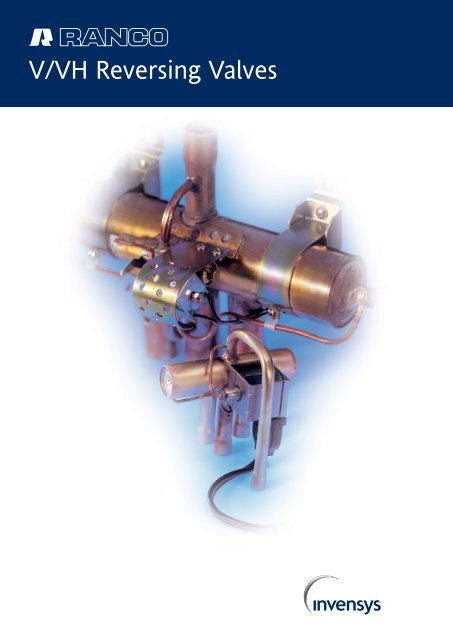
V/VH Reversing Valves
The V and VH series cycle reversing<br />
valves are used in all refrigeration<br />
applications where it is necessary<br />
to reverse refrigerant flow. They<br />
are primarily used in heat pump<br />
units for civil and industrial<br />
applications, but they are also<br />
largely used in hot gas defrost<br />
systems and in special process<br />
applications.<br />
V and VH valves - compatible with<br />
old and new refrigerants - offer a<br />
choice of capacities ranging from<br />
1,000 to 540,000 W and are<br />
available in several configurations<br />
and connection tube diameters, to<br />
satisfy the most varied application<br />
needs.
V AND VH SERIES RANCO REVERSING VALVES<br />
Les soupapes d'inversion de cycle V et VH<br />
sont utilisées dans toutes les applications<br />
frigorifiques qui nécessitent l'inversion du<br />
flux réfrigérant. Elles sont principalement<br />
employées dans les unités à pompe de<br />
chaleur pour des applications civiles et<br />
industrielles, mais elles sont aussi largement<br />
utilisées dans les installations de dégivrage<br />
à gaz chaud et dans de spéciales<br />
applications de procédés. Les soupapes V<br />
et VH, compatibles avec les anciens et les<br />
nouveaux réfrigérants, couvrent une gamme<br />
de capacité allant de 1.000 à 540.000<br />
W, et elles existent en plusieurs configurations<br />
et diamètres de tubes de connexion<br />
afin de satisfaire les différentes exigences<br />
d'application.<br />
Le valvole di inversione di ciclo V e VH<br />
vengono utilizzate in tutte le applicazioni<br />
frigorifere dove è necessario invertire il<br />
flusso refrigerante. Il loro maggiore impiego<br />
è nelle unità a pompa di calore per applicazioni<br />
civili ed industriali, ma vengono<br />
largamente utilizzate anche negli impianti<br />
con sbrinamento a gas caldo, ed in applicazioni<br />
speciali di processo. Le valvole V<br />
e VH, compatibili con vecchi e nuovi<br />
refrigeranti, coprono una gamma di<br />
capacità compresa tra 1.000 e 540.000<br />
W, e sono disponibili in varie configurazioni<br />
e diametri dei tubi di connessione, per<br />
soddisfare le differenti esigenze applicative.<br />
Die Umkehrventile der Serie V und VH<br />
werden eingesetzt in allen Kühlgeräten, in<br />
denen eine Kältekreislaufumkehrung<br />
erforderlich ist. Vorrangig werden sie in<br />
(Haushalts- oder Industrie-) Wärmepumpen<br />
eingesetzt, aber auch in Heißgas-<br />
Abtausystemen. V und VH Ventile können<br />
mit "alten" und neuen Kältemitteln arbeiten<br />
und sind in Ausführungen zwischen 1.000<br />
bis 540.000 W sowie in verschiedenen<br />
Leistungen und Rohranschluß-Durchmessern<br />
erhältlich.<br />
Las válvulas de inversión de ciclo V y VH<br />
se emplean en todas las aplicaciones<br />
frigoríficas en las que sea necesario invertir<br />
el flujo del refrigerante. Su principal empleo<br />
es en las unidades de bomba de calor<br />
para aplicaciones tanto civiles como<br />
industriales, pero también son ampliamente<br />
utilizadas en instalaciones con descarche<br />
por gas caliente y en aplicaciones<br />
especiales de proceso. Las válvulas V y<br />
VH, compatibles con los refrigerantes<br />
nuevos y antiguos, cubren una gama de<br />
capacidades que va de 1.000 a 540.000<br />
W, y están disponibles en distintas<br />
configuraciones y con distintos diámetros<br />
de tubos de conexión, para satisfacer las<br />
más variadas exigencias aplicativas.
V SERIES VALVES<br />
TECHNICAL SPECIFICATIONS<br />
Lowest\/Highest ∆∆P<br />
to reverse:<br />
15\/440 psi (400 psi for V12)<br />
Highest operating pressure:<br />
680 psi (500 psi for V12)<br />
Lowest bursting pressure:<br />
2.500 psi<br />
Highest operating:<br />
temperature<br />
250°F (120°C)<br />
Minimum number of cycles:<br />
135.000<br />
Mounting position: any<br />
•<br />
•<br />
•<br />
•<br />
•<br />
•<br />
Valves are completed by the<br />
corresponding L30 and LB coils,<br />
available in several power supply<br />
combinations and with different<br />
lead lengths.
SPECIFICATIONS TECHNIQUES<br />
DES SOUPAPES SERIE V<br />
• Minimum/Maximum ∆P pour effectuer<br />
l'inversion: 15/440 psi (400 psi pour V12)<br />
• Pression maximum de fonctionnement:<br />
680 psi (500 psi pour V12) • Pression<br />
minimum d'explosion: 2.500 psi<br />
• Température maximum de<br />
fonctionnement: 250°F (120°C) • Nombre<br />
de cycles minimum: 135.000 • Position<br />
de montage: quelconque<br />
TECHNISCHE SPEZIFIKATION<br />
SERIE V<br />
• Min./Max.- Druck für Umschaltung:<br />
15/440 psi (400 psi / V12) • Max.<br />
Betriebsdruck: 680 psi (500 psi / V12)<br />
• Berstdruckl: 2.500 psi • Max.<br />
Betriebstemperatur: 250°F (120°C)<br />
• Schaltzyklen min.: 135.000<br />
• Einbauposition: Lage unabhängig<br />
SPECIFICHE TECNICHE VALVOLE<br />
SERIE V<br />
• Minimo/Massimo ∆P per operare<br />
l'inversione: 15/440 psi (400 psi per V12)<br />
• Massima Pressione di funzionamento:<br />
680 psi (500 psi per V12) • Minima<br />
pressione di scoppio: 2.500 psi • Massima<br />
temperatura di funzionamento: 250°F<br />
(120°C) • Numero minimo di cicli:<br />
135.000 • Posizione di montaggio:<br />
qualsiasi<br />
CARACTERÍSTICAS TÉCNICAS<br />
DE LAS VÁLVULAS DE LA SERIE V<br />
• Mínimo/Máximo ∆P para realizar la<br />
inversión: 15/440 psi (400 psi para V12)<br />
• Máxima presión de funcionamiento: 680<br />
psi (500 psi para V12) • Mínima presión<br />
de explosión: 2.500 psi • Temperatura<br />
máxima de funcionamiento: 250°F (120°C)<br />
• Número mínimo de ciclos: 135.000<br />
• Posición de montaje: cualquiera<br />
BASE<br />
CODE (=)<br />
V1<br />
V2<br />
V3<br />
V4<br />
V6<br />
V10<br />
V12<br />
CAPACITY WATT (R22)<br />
MIN MAX<br />
1400<br />
2625 (3500)<br />
3500<br />
3500<br />
3500<br />
10500<br />
17500<br />
3500<br />
7000 (8750)<br />
9800 (10500)<br />
14000<br />
19250<br />
29750 (33250)<br />
42000<br />
L30 COILS FOR V SERIES VALVES<br />
STANDARD<br />
MODEL<br />
L30 124801<br />
L30 324801<br />
L30 424801<br />
L30 734801<br />
L30 834801<br />
CAPACITY WATT (R134)<br />
MIN MAX<br />
1400<br />
2450 (3150)<br />
3150<br />
3150<br />
3150<br />
9800<br />
16450<br />
24V AC<br />
120V AC<br />
240V AC<br />
12V DC<br />
24V DC<br />
ELECTRICAL<br />
RATINGS<br />
50/60 Hz<br />
50/60 Hz<br />
50/60 Hz<br />
6/4W<br />
6/4W<br />
6/4W<br />
9W<br />
9W<br />
INSULATION<br />
CLASS<br />
B<br />
B<br />
B<br />
F<br />
F<br />
LEAD<br />
LENGHT<br />
1220 mm (48”)<br />
1220 mm (48”)<br />
1220 mm (48”)<br />
1220 mm (48”)<br />
1220 mm (48”)<br />
Tolerance: -15\+10% of rated voltage value. Different lead lengths are available on request.<br />
Les soupapes sont équipées des relatives<br />
bobines L30 et LB, existant en différentes<br />
combinaisons d'alimentation électrique et<br />
dimensions de câbles.<br />
Le valvole vengono completate dalle relative<br />
bobine L30 ed LB, disponibili in varie<br />
combinazioni di alimentazione elettrica e<br />
differenti misure di cavi.<br />
3500<br />
4900 (5250)<br />
6650 (7700)<br />
10150<br />
14700<br />
22050 (25550)<br />
32550<br />
INT. LEAK<br />
MAX CC/MIN.<br />
Values refer to use with reciprocating compressor and under the following conditions: • Evaporation temp.: 45°F • Condensing temp.: 130°F • Superheat: 10°F • Undercooling: 10°F • ∆P at suction side: 2 psi.<br />
(=) To complete valve code, add the alphanumeric references concerning tube diameter and geometry to the base code. Rated capacity values between brackets refer to specific V2, V3 and V10 codes.<br />
2000<br />
2000<br />
2000<br />
4000<br />
4000<br />
6000<br />
15000<br />
Die Magnetspule L30 und LB gibt es in<br />
unterschiedlichen Spannungen und<br />
Kabellängen.<br />
Las válvulas se completan con las<br />
respectivas bobinas L30 y LB, disponibles<br />
en varias combinaciones de alimentación<br />
eléctrica y con distintas medidas de cables.<br />
AVAILABLE<br />
TUBE GEOMETRY<br />
A, B<br />
A, B<br />
E<br />
A<br />
A<br />
A<br />
F<br />
TUBE DIAMETER<br />
DELIVERY SIDE SUCTION SIDE, L, R<br />
1 /4, 5 /16, 3 /8<br />
1 /4, 5 /16, 3 /8<br />
5 /8, 3 /4<br />
1 /2, 5 /8, 3 /4<br />
3 /8, 1 /2, 5 /8, 3 /4<br />
1 /2, 5 /8, 3 /4, 7 /8<br />
1 1 /8<br />
3 /8, 1 /2<br />
3 /8, 1 /2<br />
5 /8, 3 /4<br />
3 /4, 7 /8<br />
3 /4, 7 /8<br />
7 /8, 1 1 /8<br />
1 1 /8
VH SERIES VALVES<br />
TECHNICAL SPECIFICATIONS<br />
Lowest\/Highest ∆∆P<br />
to reverse:<br />
50/330 psi<br />
Highest operating pressure:<br />
435 psi<br />
Lowest bursting pressure:<br />
2.175 psi<br />
Highest operating:<br />
temperature<br />
250°F (120°C)<br />
Minimum number of cycles:<br />
10.000<br />
Mounting position: horizontal •<br />
•<br />
•<br />
•<br />
•<br />
•
SPECIFICATIONS TECHNIQUES<br />
DES SOUPAPES SERIE VH<br />
• Minimum/Maximum ∆P pour effectuer<br />
l'inversion: 50/330 psi • Pression maximum<br />
de fonctionnement: 435 psi<br />
• Pression minimum d'explosion: 2.175 psi<br />
• Température maximum de fonctionnement:<br />
250°F (120°C) • Nombre de cycles<br />
minimum: 10.000 • Position de mon-tage:<br />
horizontale<br />
TECHNISCHE SPEZIFIKATION<br />
SERIE VH<br />
• Min./Max.- Druck für Umschaltung:<br />
50/330 psi • Max. Betriebsdruck: 435 psi<br />
• Min. Berst-druck: 2.175 psi • Max.<br />
Betriebstemperatur: 250°F (120°C)<br />
• Schaltzyklen min.: 10.000<br />
• Einbauposition: horizontal.<br />
SPECIFICHE TECNICHE VALVOLE<br />
SERIE VH<br />
• Minimo/Massimo ∆P per operare<br />
l'inversione: 50/330 psi • Massima<br />
Pressione di funziona-mento: 435 psi<br />
• Minima pressione di scoppio: 2.175 psi<br />
• Massima temperatura di funziona-mento:<br />
250°F (120°C) • Numero minimo di cicli:<br />
10.000 • Posizione di montaggio:<br />
orizzontale<br />
CARACTERÍSTICAS TÉCNICAS<br />
DE LAS VÁLVULAS DE LA SERIE VH<br />
• Mínimo/Máximo ∆P para realizar la<br />
inversión: 50/330 psi • Máxima Presión<br />
de funcionamiento: 435 psi • Mínima<br />
presión de explosión: 2.175 psi<br />
• Temperatura máxima de funcionamiento:<br />
250°F (120°C) • Número mínimo de ciclos:<br />
10.000 • Posición de montaje: horizontal<br />
MODEL<br />
VH7 0100C<br />
VH6<br />
VH5<br />
VH1 0110<br />
VH4 0100<br />
VH1 0112<br />
VH2 0311<br />
VH2 0312<br />
VH9 0110<br />
VH3 1084<br />
VH3 1122<br />
VH3 1162<br />
CAPACITY WATT (R22)<br />
MIN MAX<br />
1000<br />
10000<br />
16000<br />
17000<br />
3500<br />
17000<br />
40000<br />
40000<br />
34000<br />
67000<br />
100000<br />
135000<br />
4900<br />
42000<br />
51000<br />
67000<br />
21000<br />
67000<br />
135000<br />
135000<br />
168000<br />
267000<br />
403000<br />
538000<br />
LB COILS FOR VH SERIES VALVES<br />
CAPACITY WATT (R134)<br />
MIN MAX<br />
1000<br />
10000<br />
12000<br />
17000<br />
3500<br />
17000<br />
35000<br />
35000<br />
27000<br />
67000<br />
100000<br />
135000<br />
STANDARD<br />
MODEL<br />
LB6 4012<br />
LB6 4023<br />
LB6 4025<br />
LB5 0013<br />
3900<br />
32000<br />
42000<br />
54000<br />
16000<br />
54000<br />
108000<br />
108000<br />
135000<br />
218000<br />
323000<br />
436000<br />
240V AC<br />
24V AC<br />
115V AC<br />
12V CC<br />
ELECTRICAL<br />
RATINGS<br />
50/60 Hz<br />
50/60 Hz<br />
INT. LEAK<br />
MAX CC/MIN.<br />
AVAILABLE<br />
TUBE GEOMETRY<br />
TUBE DIAMETER<br />
DELIVERY SIDE SUCTION SIDE, L, R<br />
Values refer to use with reciprocating compressor and under the following conditions: • Evaporation temp.: 45°F • Condensing temp.: 130°F • Superheat: 10°F • Undercooling: 10°F • ∆P at suction side: 2 psi.<br />
A*: preassembled multi-valve units connected in parallel, single pilot.<br />
1000<br />
6000<br />
5000<br />
10000<br />
4000<br />
10000<br />
15000<br />
15000<br />
20000<br />
30000<br />
45000<br />
60000<br />
60 Hz<br />
6/4W<br />
6/4W<br />
6W<br />
8W<br />
Tolerance: -15\+10% of rated voltage value. Different wire lengths are available on request.<br />
B<br />
A<br />
A<br />
A<br />
A<br />
A<br />
A<br />
A<br />
A<br />
A*<br />
A*<br />
A*<br />
INSULATION<br />
CLASS<br />
F<br />
F<br />
F<br />
E<br />
8<br />
-<br />
19.05<br />
3 /4”<br />
22.2<br />
7 /8”<br />
22.2<br />
7 /8”<br />
25.4<br />
1”<br />
12.7<br />
1 /2”<br />
28.6<br />
1 1 /8”<br />
38.1<br />
1 1 /2”<br />
41.28<br />
1 5 /8”<br />
38.1<br />
1 1 /2”<br />
FRANGE<br />
RBK 50A<br />
FRANGE<br />
RBK 50A<br />
FRANGE<br />
RBK 50A<br />
LEAD<br />
LENGHT<br />
1000 mm<br />
1500 mm<br />
1000 mm<br />
1000 mm<br />
ø 9.52<br />
3 /8”<br />
22.2<br />
7 /8”<br />
28.6<br />
1 1 /8”<br />
28.6<br />
1 1 /8”<br />
31.75<br />
1 1 /4”<br />
19.05<br />
3 /4”<br />
35.0<br />
1 3 /8”<br />
44.45<br />
1 3 /4”<br />
41.28<br />
1 5 /8”<br />
54.0<br />
2 1 /8”<br />
FRANGE<br />
RBK 65A<br />
FRANGE<br />
RBK 65A<br />
FRANGE<br />
RBK 65A
BRANCHEMENT A L'INSTALLATION<br />
ANSCHLUß ANS SYSTEM<br />
COLLEGAMENTO ALL'IMPIANTO<br />
CONEXIÓN CON LA INSTALACIÓN<br />
CONNECTION TO THE SYSTEM
TUBE STYLES<br />
A<br />
B<br />
C<br />
D<br />
E<br />
F<br />
∆P<br />
PSI<br />
4<br />
3<br />
2<br />
1<br />
.5<br />
.4<br />
SUCTION PRESSURE DROP CHART (R22)<br />
1050<br />
1400<br />
1750<br />
CAPACITY, WATT<br />
1050000<br />
700000<br />
35000<br />
175000<br />
105000<br />
35000<br />
28000<br />
21000<br />
14000<br />
7000<br />
3500<br />
1750<br />
1050<br />
700<br />
3500<br />
4 WAY REVERSING VALVES CAPACITY TABLE<br />
0.01<br />
(0.01)<br />
V4<br />
V3 WITH 5/8 SUCTION<br />
V3 WITH 3/4 SUCTION<br />
V2 WITH 1/2 SUCTION 3/8 HIGH PRESSURE<br />
V2 WITH 5/8 SUCTION 3/8 HIGH PRESSURE<br />
V1 WITH 1/2 SUCTION 5/16 HIGH PRESSURE<br />
V6<br />
.3<br />
.25<br />
1 2 5 10 20 50 100 200<br />
FLOW RATE, LBS/MIN<br />
5250<br />
7000<br />
10500<br />
14000<br />
17500<br />
REFRIGERATION CAPACITY, WATT<br />
V10<br />
V12<br />
0.1<br />
(0.1) 0.14<br />
(0.14) 0.2<br />
(0.2)<br />
35000<br />
52500<br />
70000<br />
105000<br />
140000<br />
175000<br />
Refrigerant R22<br />
VH3 1162<br />
VH3 1122<br />
VH3 1084<br />
VH9 0110<br />
VH2 0311 VH2 0312<br />
VH1 0110 VH1 0112<br />
VH5 110D<br />
VH6 0100 VH6 1100<br />
VH4 0100<br />
V38 110C<br />
V26 110D<br />
V26 110B VS6 100B<br />
VH7 100C<br />
0.5<br />
(0.5)<br />
SUCTION PRESSURE DROP MPa (kg/cm 2 )<br />
x 10 -1
MOUNTING INSTRUCTIONS<br />
You should ALWAYS connect HP tube<br />
to compressor delivery (high<br />
pressure) side and LP tube to<br />
compressor suction<br />
(low pressure) side.<br />
When brazing, valve body should<br />
not be exposed to temperatures<br />
exceeding 250°F (120°C); we<br />
therefore recommend protecting the<br />
valve by wrapping it with wet rags.<br />
Make sure that there is enough<br />
refrigerant charge; should<br />
refrigerant charge be too low,<br />
an incomplete exchange<br />
of slide could occur.<br />
For further information, please call<br />
our engineering department.
INSTRUCTIONS POUR LE MONTAGE<br />
Il faut TOUJOURS relier le tube HP au<br />
refoulement du compresseur et le tube LP à<br />
l'aspiration.Pendant la soudure, le corps de<br />
la soupape ne doit pas être exposé à des<br />
températures supérieures à 250°F (120°C);<br />
nous conseillons donc de protéger la soupape<br />
en l'enveloppant dans des chiffons mouillés.<br />
Contrôler que la charge de réfrigérant est<br />
suffisante; une charge insuffisante peut<br />
provoquer un échange incomplet du<br />
coulisseau. Pour tout renseignement<br />
supplémentaire veuillez consulter notre service<br />
technique.<br />
EINBAU-ANWEISUNG<br />
Bitte verwenden Sie IMMER - zur<br />
Verbesserung der Umkehreigenschaften -<br />
den hohen Druck der Hochdruckseite und<br />
den niedrigen Druck der Saugseite. Dies<br />
verbessert die Umkehreigenschaften und<br />
somit das Schieben/Ziehen des<br />
Hauptventilschiebers. Während des Einlötens<br />
ist der Ventilkörper abzukühlen (mit nassem<br />
Lappen umwickeln), damit seine Temperatur<br />
120°C nicht überschreitet. Stellen Sie sicher,<br />
daß genug Kältemittel zur Verfügung steht.<br />
Sollte der Kältemittelstand zu niedrig sein,<br />
besteht die Gefahr, daß der Schieber nicht<br />
vollständig öffnet/schließt. Für weitere<br />
Informationen steht Ihnen unsere technische<br />
Abteilung zur Verfügung.<br />
ISTRUZIONI MONTAGGIO<br />
Collegare SEMPRE il tubo HP alla mandata<br />
del compressore e il tubo LP all'aspirazione.<br />
In fase di saldatura il corpo valvola non<br />
deve essere esposto a temperature superiori<br />
a 250°F (120°C); si consiglia quindi di<br />
proteggere la valvola avvolgendola con<br />
stracci bagnati. Assicurarsi che la carica di<br />
refrigerante sia sufficiente; una carica troppo<br />
bassa può provocare l'incompleto scambio<br />
della slitta. Per ulteriori informazioni vogliate<br />
consultare il Ns. servizio tecnico.<br />
INSTRUCCIONES DE MONTAJE<br />
Conecte SIEMPRE el tubo HP a la descarga<br />
del compresor y el tubo LP a la succión.<br />
Durante la soldadura, no hay que exponer<br />
el cuerpo de la válvula a temperaturas<br />
superiores a 250°F (120°C); por lo tanto,<br />
le aconsejamos que proteja la válvula,<br />
envolviéndola con trapos húmedos.<br />
Asegúrese de que la carga del refrigerante<br />
sea suficiente; una carga demasiado baja,<br />
puede provocar el intercambio incompleto<br />
de la corredera. Para mayor información,<br />
consulte a nuestro servicio técnico.<br />
Solenoid Coil Energized<br />
Heating Cycle<br />
(Refrigerant Flow)<br />
Solenoid Coil De-energized<br />
Cooling Cycle<br />
(Refrigerant Flow)<br />
Solenoid Coil Energized<br />
Cooling Cycle<br />
(Refrigerant Flow)<br />
Solenoid Coil De-energized<br />
Heating Cycle<br />
(Refrigerant Flow)
Sales:<br />
Invensys Controls Italy S.R.L.<br />
Via dell’Artigianato, 65<br />
32010 Pieve d’Alpago<br />
Belluno - Italy<br />
Ph. +39 0437 986 111<br />
Fax +39 0437 989 066<br />
Invensys Climate Controls ltd<br />
Cordwallis Street<br />
Maidenhead SL6 7BQ<br />
United Kingdom<br />
Ph. +44 (0) 1628 672 121<br />
Fax +44 (0) 1895 421 901<br />
Eberle Controls GmbH<br />
Klingenhofstrasse 71<br />
90411 Nuernberg<br />
Germany<br />
Ph. +49 (0) 911 5693 0<br />
Fax +49 (0) 911 5693 536<br />
For technical queries:<br />
Ranco Controls ltd<br />
401, Southway Drive<br />
Southway Plymouth<br />
Plymouth Devon PL6 6QT<br />
Ph. +44 (0) 1752 737 166<br />
Fax +44 (0) 1752 696 536<br />
polaris - CT122461 - n° 1500 - 12/00 - Specifications subject to change without notice - Les caractéristiques techniques sont sujettes à modifications sans préavis - Technische Änderungen unter Vorbehalt<br />
- Le caratteristiche tecniche sono soggette a variazioni senza preavviso - Las características técnicas están sujetas a cambios sin previo aviso.