KITY 2636 - Woodworking.de
KITY 2636 - Woodworking.de
KITY 2636 - Woodworking.de

You also want an ePaper? Increase the reach of your titles
YUMPU automatically turns print PDFs into web optimized ePapers that Google loves.
Defective electrical power lines<br />
Often there are isolation <strong>de</strong>fects in electrical power lines.<br />
Possible causes:<br />
• Dents, when the power line was installed through a window<br />
or doorway.<br />
• Cracks resulting from an improper mound or installation<br />
of the power line.<br />
• Cuts from passing around the power line.<br />
• Isolation <strong>de</strong>fects due to pulling out the wall socket.<br />
• Rifts because of changes in isolation. Such <strong>de</strong>fective<br />
electrical power lines must not be used and are, due to<br />
isolation <strong>de</strong>fects life-threatening!<br />
Check the electrical power line regularly for <strong>de</strong>fects. Make<br />
sure that the power line is not connected to the power<br />
supply system during checkup. The power lines must meet<br />
the VDE- and DIN-regulations, as well as the local EVEregulations.<br />
Use only the power lines with the mark H 07<br />
RN. An i<strong>de</strong>ntification on the cable of the type of line is<br />
mandatory.<br />
Extension cables must be up to 25 m per each 1,5 squared<br />
millimeter section, over 25 m long for a section of at least<br />
2,5 squared millimeters.<br />
The power connection must be supported by a 16 A fuse.<br />
Rotary motor<br />
Line voltage must be 380÷420 V 50 Hz.<br />
Power connection and extension cabling must be up to 5<br />
cores (5adrig) =3 P + N + SL.<br />
Extension cables must cover a section of at least 1,5 mm².<br />
The power connection should optimally be secured by 16 A.<br />
The rotation direction must be checked after connection to<br />
the power or moving the machine, if necessary, the polarity<br />
must be changed.<br />
Connection and repairs of the electrical equipment should<br />
only be done by an electrician.<br />
For inquiries, please have the following information:<br />
• Motor manufacturer; motor type<br />
• Electrical type of the motor<br />
• The machine/type plate information<br />
• Electrical control system information<br />
When sending back the machine, please inclu<strong>de</strong> the complete<br />
propulsion unit with the electrical control system.<br />
14 english<br />
Maintenance<br />
Conduct maintenance, repair and cleaning, as well as malfunction<br />
check, only with the unit shut off. Use the on-off<br />
switch to shut down the machine and then disconnect<br />
from the oulet!<br />
All guard and safety instructions must be immediately<br />
mounted after repair and servicing work.<br />
The work table, as well as the thicknessing table must be<br />
kept free of resin. Use long-term lubrication for the storage<br />
of the planer shaft and the tool spindle. In new conditions,<br />
warming is part of the <strong>de</strong>sign but it goes away after<br />
some time.<br />
Clean the fee<strong>de</strong>r cylin<strong>de</strong>rs regularly.<br />
Oil the bearing and shaft with hinges of the sliding bearing<br />
of the fee<strong>de</strong>r cylin<strong>de</strong>rs and the adjustment spindle of the<br />
thicknessing table after the first 5 hours of operation. After<br />
that, oil every 20 hours of operation.<br />
Check the chain tension. If nee<strong>de</strong>d, tighten and oil it.<br />
When tightening the thicknessing table chain, pay atten-<br />
tion to the prallelism of the thicknessing table.<br />
Planer bla<strong>de</strong>s<br />
The planer bla<strong>de</strong>s at work are beveled and setup correctly,<br />
ready for use.<br />
Only well-sharpened and exactly set planer bla<strong>de</strong>s can<br />
guarantee safe operation.<br />
We recommend:<br />
Always keep a spare beveled planer bla<strong>de</strong> ready, in need<br />
of replacement.<br />
Beveling planer bla<strong>de</strong>s<br />
Dull planer bla<strong>de</strong>s raise the risk of acci<strong>de</strong>nts, the work efficiency<br />
is no longer guaranteed.<br />
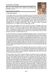
1Screw for adjustment<br />
2Tightening screw<br />
3Planer cutter<br />
4Cutter hol<strong>de</strong>r<br />
5Tightening wedge shaped part<br />
Do not forget while setting the cutters :<br />
•That there is a risk of injury for the fingers and hands.<br />
•That the tightening surfaces of the cutter block and the<br />
wedge shaped parts must be cleaned<br />
•That the sharp cutters are free of oil<br />
•That the adjustment and positioning of the cutters, of the<br />
cutter hol<strong>de</strong>rs and of the tightening wedge shaped parts<br />
has to be done according to the drawing ( N°)<br />
•That the cutters, cutter hol<strong>de</strong>rs and tightening of wedge<br />
shaped parts have to fit as one unit on both si<strong>de</strong>s of the<br />
cutter block (explication )<br />
•That all tightening screws have to be well screwed (8,9<br />
N/m)<br />
Caution !<br />
The indications relative to the fixation of cutters, to the position<br />
of the cutters, to their thickness, to the minimum fixing<br />
length and to the screwing value have to be followed with<br />
precision.<br />
Adjustment of the cutter bla<strong>de</strong>s Fig 17, Fig 17.1<br />
•The adjustment of the cutter bla<strong>de</strong>s has been done at the<br />
factory. When nee<strong>de</strong>d, you can operate as follows to make<br />
a fine adjustment:<br />
•Adjust one cutter bla<strong>de</strong> after the other.<br />
•Adjust the cutter bla<strong>de</strong> in height in or<strong>de</strong>r to touch the two<br />
perfectly planed pieces of wood you have to put right and<br />
left on the outlet surfacing table.<br />
•Set the inlet table at stock removal of 2 mm.<br />
•Turn the cutter block to position the cutter bla<strong>de</strong> at its<br />
highest position.<br />
•While the cutter hol<strong>de</strong>r is touching the head of the adjusting<br />
screws placed at the bottom of the cavity of the cutter<br />
block, release the fixing screws of the cutter with the<br />
wrench (C ) to rise the cutter until it touches both pieces<br />
of wood.<br />
•Adjust exactly , tighten the cutter hol<strong>de</strong>r and check the<br />
position of the cutter bla<strong>de</strong>s again.<br />
Checking of the position of the cutter bla<strong>de</strong>s:<br />
Put a well surfaced piece of wood on the outlet table and<br />
mark its position.<br />
While turning the cutter block in the cutting direction, the