KITY 2636 - Woodworking.de
KITY 2636 - Woodworking.de
KITY 2636 - Woodworking.de

Create successful ePaper yourself
Turn your PDF publications into a flip-book with our unique Google optimized e-Paper software.
07-2009<br />
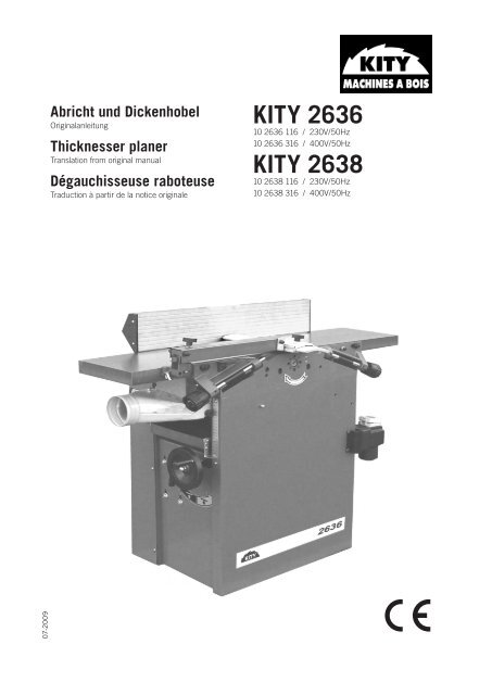
Abricht und Dickenhobel<br />
Originalanleitung<br />
Thicknesser planer<br />
Translation from original manual<br />
Dégauchisseuse raboteuse<br />
Traduction à partir <strong>de</strong> la notice originale<br />
<strong>KITY</strong> <strong>2636</strong><br />
10 <strong>2636</strong> 116 / 230V/50Hz<br />
10 <strong>2636</strong> 316 / 400V/50Hz<br />
<strong>KITY</strong> 2638<br />
10 2638 116 / 230V/50Hz<br />
10 2638 316 / 400V/50Hz
2 international
Hersteller:<br />
Scheppach Fabrikation von Holzbearbeitungsmaschinen GmbH<br />
Günzburger Str. 69<br />
D-89335 Ichenhausen<br />
Verehrter Kun<strong>de</strong>,<br />
Wir wünschen Ihnen viel Freu<strong>de</strong> und Erfolg beim Arbeiten<br />
mit Ihrer neuen Maschine.<br />
Hinweis:<br />
Der Hersteller dieses Gerätes haftet nach <strong>de</strong>m gelten<strong>de</strong>n<br />
Produkthaftungsgesetz nicht für Schä<strong>de</strong>n, die an diesem<br />
Gerät o<strong>de</strong>r durch dieses Gerät entstehen bei:<br />
• unsachgemäßer Behandlung,<br />
• Nichtbeachtung <strong>de</strong>r Bedienungsanweisung,<br />
• Reparaturen durch Dritte, nicht autorisierte Fachkräfte,<br />
• Einbau und Austausch von nicht originalen Ersatzteilen,<br />
• nicht bestimmungsgemäßer Verwendung,<br />
• Ausfällen <strong>de</strong>r elektrischen Anlage bei Nichtbeachtung<br />
<strong>de</strong>r elektrischen Vorschriften und VDE-Bestimmungen<br />
0100, DIN 57113 / VDE 0113.<br />
Wir empfehlen Ihnen:<br />
Lesen Sie vor <strong>de</strong>r Montage und vor Inbetriebnahme <strong>de</strong>n<br />
gesamten Text <strong>de</strong>r Bedienungsanweisung durch.<br />
Diese Bedienungsanweisung soll es Ihnen erleichtern, Ihre<br />
Maschine kennenzulernen und ihre bestimmungsgemäßen<br />
Einsatzmöglichkeiten zu nutzen.<br />
Die Bedienungsanweisung enthält wichtige Hinweise, wie<br />
Sie mit <strong>de</strong>r Maschine sicher, fachgerecht und wirtschaftlich<br />
arbeiten, und wie Sie Gefahren vermei<strong>de</strong>n, Reparaturkosten<br />
sparen, Ausfallzeiten verringern und die Zuverlässigkeit<br />
und Lebensdauer <strong>de</strong>r Maschine erhöhen.<br />
Zusätzlich zu <strong>de</strong>n Sicherheitsbestimmungen dieser Bedienungsanweisung<br />
müssen Sie unbedingt die für <strong>de</strong>n Betrieb<br />
<strong>de</strong>r Maschine gelten<strong>de</strong>n Vorschriften Ihres Lan<strong>de</strong>s beachten.<br />
Die Bedienungsanweisung, in einer Plastikhülle geschützt<br />
vor Schmutz und Feuchtigkeit, bei <strong>de</strong>r Maschine aufbewahren.<br />
Sie muss von je<strong>de</strong>r Bedienungsperson vor Aufnahme<br />
<strong>de</strong>r Arbeit gelesen und sorgfältig beachtet wer<strong>de</strong>n. An <strong>de</strong>r<br />
Maschine dürfen nur Personen arbeiten, die im Gebrauch<br />
<strong>de</strong>r Maschine unterwiesen und über die damit verbun<strong>de</strong>nen<br />
Gefahren unterrichtet sind. Das gefor<strong>de</strong>rte Min<strong>de</strong>stalter<br />
ist einzuhalten.<br />
Allgemeine Hinweise<br />
• Überprüfen Sie nach <strong>de</strong>m Auspacken alle Teile auf eventuelle<br />
Transportschä<strong>de</strong>n. Bei Beanstandungen muss sofort<br />
<strong>de</strong>r Zubringer verständigt wer<strong>de</strong>n. Spätere Reklamationen<br />
wer<strong>de</strong>n nicht anerkannt.<br />
• Überprüfen Sie die Sendung auf Vollständigkeit.<br />
• Machen Sie sich vor <strong>de</strong>m Einsatz anhand <strong>de</strong>r Bedienungsanweisung<br />
mit <strong>de</strong>m Gerät vertraut.<br />
• Verwen<strong>de</strong>n Sie bei Zubehör sowie Verschleiß- und Ersatzteilen<br />
nur Original-Teile. Ersatzteile erhalten Sie bei<br />
Ihrem -Fachhändler.<br />
• Geben Sie bei Bestellungen unsere Artikelnummern sowie<br />
Typ und Baujahr <strong>de</strong>s Gerätes an.<br />
Lieferumfang:<br />
<strong>2636</strong> und 2638<br />
Hobelmaschine<br />
<strong>KITY</strong> <strong>2636</strong> und <strong>KITY</strong> 2638<br />
Hobelwellenschutz<br />
Kombinierte Absaughaube<br />
Montagezubehör (Beipackbeutel)<br />
Bedienungsanweisung<br />
Technische Daten <strong>2636</strong> 2638<br />
Baumaße L x B x H mm 1085x610x950 1610x700x950<br />
Tischhöhe mm 805 825<br />
Abrichttisch L x B mm 1085x255 1610x320<br />
Dickentisch L x B mm 600x248 750x308<br />
Gewicht kg 150 345<br />
Hobelwelle<br />
Hobelwellen ø mm 75 95<br />
Messerflugkreis ø mm 77 99<br />
Drehzahl max. 1/min 4000 4000<br />
Anzahl <strong>de</strong>r Hobelmesse 3 4<br />
Hobelmesser<br />
Vrschub<br />
Wen<strong>de</strong>platten-Hobelmesser<br />
Anzahl Vorschubwalzen 2 2<br />
Vorschubwalzen ø mm 32 42<br />
Länge mm 365 460<br />
Vorschubgeschwindigkeit<br />
m/min<br />
8 8<br />
Abschaltbar Oui Oui<br />
Antrieb<br />
Motor V/Hz<br />
Aufnahmeleistung<br />
P1 W<br />
2000 2200 2200 2200<br />
Abgabeleistung P2 W 1500 1700 1700 1700<br />
Drehzahl 1/min 280 2800 2800 2800<br />
Betriebsart S1 S1 S1 S1<br />
Arbeitsdaten<br />
Abricht breite max. mm 250 310<br />
Spandicke Abrichten<br />
max. mm<br />
5 5<br />
Hobelbreite Dickten<br />
max. mm<br />
Spandicke Dickten<br />
max. mm<br />
Durchlaß Dickten<br />
min/max. mm<br />
247 306<br />
2 5<br />
5/180 8/220<br />
// Anschlag Winkel 90–45° 90-45°<br />
Anschlaglänge mm 700 1100<br />
Anschlaghöhe mm 130 130<br />
Technische Än<strong>de</strong>rungen vorbehalten!<br />
Geräuschkennwerte<br />
Die nach EN 23746 für <strong>de</strong>n Schalleistungspegel bzw.<br />
EN 31202 (Korrekturfaktor k3 nach Anhang A.2 von EN<br />
31204 berechnet) für <strong>de</strong>n Schalldruckpegel am Arbeitsplatz<br />
ermittelten Geräuschemissionswerte betragen unter<br />
Zugrun<strong>de</strong>legung <strong>de</strong>r in ISO 7904 Anhang A aufgeführten<br />
Arbeitsbedingungen.<br />
Schalleistungspegel in dB (Abrichten)<br />
Leerlauf L WA = 89 dB(A)<br />
Bearbeitung L WA = 98,5 dB(A)<br />
<strong>de</strong>utsch 3
Schalldruckpegel am Arbeitsplatz in dB<br />
Leerlauf L pAeq = 85,5 dB(A)<br />
Bearbeitung L pAeq = 92 dB(A)<br />
Schalleistungspegel in dB (Dickten)<br />
Leerlauf L WA = 107 dB(A)<br />
Bearbeitung L WA = 108 dB(A)<br />
Schalldruckpegel am Arbeitsplatz in dB<br />
Leerlauf L pAeq = 94 dB(A)<br />
Bearbeitung L pAeq = 94,5 dB(A)<br />
Die angegebenen Werte sind Emissionswerte und müssen<br />
damit nicht zugleich auch sichere Arbeitsplatzwerte darstellen.<br />
Obwohl es eine Korrelation zwischen Emissions-<br />
und Immissionspegeln gibt, kann daraus nicht zuverlässig<br />
abgeleitet wer<strong>de</strong>n, ob zusätzliche Vorsichtsmaßnahmen<br />
notwendig sind o<strong>de</strong>r nicht. Faktoren, welche <strong>de</strong>n aktuellen<br />
am Arbeitzplatz vorhan<strong>de</strong>n Immissionspegel beeinflussen,<br />
beinhalten die Eigenart <strong>de</strong>s Arbeitsraumes, an<strong>de</strong>re Geräuschquellen,<br />
z.B. die Zahl <strong>de</strong>r Maschinen und an<strong>de</strong>rer<br />
benachbarter Arbeitsvorgänge. Die zulässigen Arbeitswerte<br />
können von Land zu Land variieren. Die Information soll<br />
jedoch <strong>de</strong>n Anwen<strong>de</strong>r befähigen, eine Abschätzung von<br />
Gefährdung und Risiko vorzunehmen.<br />
In dieser Bedienungsanweisung haben wir Stellen, die Ihre<br />
Sicherheit betreffen, mit diesem Zeichen versehen:<br />
4 <strong>de</strong>utsch<br />
Allgemeine Sicherheitshinweise<br />
Schulung <strong>de</strong>r Betreiber<br />
• Geben Sie die Sicherheitshinweise an alle Personen<br />
weiter, die an <strong>de</strong>r Maschine arbeiten.<br />
• Die Bedienungsperson muß min<strong>de</strong>stens 18 Jahre alt<br />
sein. Auszubil<strong>de</strong>n<strong>de</strong> müssen min<strong>de</strong>stens 16 Jahre alt<br />
sein, dürfen aber nur unter Aufsicht an <strong>de</strong>r Maschine<br />
arbeiten.<br />
• An <strong>de</strong>r Maschine tätige Personen dürfen nicht abgelenkt<br />
wer<strong>de</strong>n.<br />
• Halten Sie Kin<strong>de</strong>r von <strong>de</strong>r an das Netz angeschlossenen<br />
Maschine fern.<br />
• Eng anliegen<strong>de</strong> Kleidung tragen. Schmuck, Ringe und<br />
Armbanduhren ablegen.<br />
• Alle Sicherheits- und Gefahrenhinweise an <strong>de</strong>r Maschine<br />
beachten und in lesbarem Zustand halten.<br />
• Vorsicht beim Arbeiten: Verletzungsgefahr für Finger<br />
und Hän<strong>de</strong> durch das rotieren<strong>de</strong> Schneidwerkzeug<br />
Standsicherheit<br />
• Achten Sie darauf, daß die Hobelmaschine beim Aufbau<br />
standsicher auf festem Grund steht.<br />
Bestimmungsgemäße Verwendung<br />
• Die Hobelmaschine ist ausschließlich mit <strong>de</strong>m angebotenen<br />
Werkzeug und Zubehör zum Bearbeiten von Holz<br />
konstruiert.<br />
• Die Maschine entspricht <strong>de</strong>r gültigen EG Maschinenrichtlinie.<br />
• Die Maschine ist für einschichtigen Betrieb ausgelegt,<br />
Einschaltdauer S1.<br />
• Alle Sicherheits- und Gefahrenhinweise an <strong>de</strong>r Maschine<br />
beachten.<br />
• Alle Sicherheits- und Gefahrenhinweise an <strong>de</strong>r Maschine<br />
vollzählig in lesbarem Zustand halten.<br />
• Bei Einsatz in geschlossenen Räumen muß die Maschine<br />
an eine Absauganlage angeschlossen wer<strong>de</strong>n.<br />
• Zum Absaugen von Holzspänen o<strong>de</strong>r Sägemehl eine Absauganlage<br />
einsetzen. Die Strömungsgeschwindigkeit<br />
am Absaugstutzen muß 20 m/s betragen. Unterdruck<br />
1200 Pa.<br />
• Für Arbeiten im gewerblichen Bereich muß zum Absaugen<br />
ein Entstauber eingesetzt wer<strong>de</strong>n.<br />
Absauganlagen o<strong>de</strong>r Entstauber bei laufen<strong>de</strong>r Arbeitsmaschine<br />
nicht abschalten o<strong>de</strong>r entfernen.<br />
• Maschine nur in technisch einwandfreiem Zustand sowie<br />
bestimmungsgemäß, sicherheits- und gefahrenbewußt<br />
unter Beachtung <strong>de</strong>r Betriebsanleitung benutzen!<br />
Insbeson<strong>de</strong>re Störungen, die die Sicherheit beeinträchtigen<br />
können, umgehend beseitigen (lassen)!<br />
• Die Sicherheits-, Arbeits- und Wartungsvorschriften <strong>de</strong>s<br />
Herstellers sowie die in <strong>de</strong>n Technischen Daten angegebenen<br />
Abmessungen müssen eingehalten wer<strong>de</strong>n.<br />
• Die zutreffen<strong>de</strong>n Unfallverhütungsvorschriften und die<br />
sonstigen, allgemein anerkannten Sicherheitstechnischen<br />
Regeln müssen beachtet wer<strong>de</strong>n.<br />
• Die Maschine darf nur von sachkundigen Personen genutzt,<br />
gewartet o<strong>de</strong>r repariert wer<strong>de</strong>n, die damit vertraut<br />
und über die Gefahren unterrichtet sind. Eigenmächtige<br />
Verän<strong>de</strong>rungen an <strong>de</strong>r Maschine schließen eine Haftung<br />
<strong>de</strong>s Herstellers für daraus resultieren<strong>de</strong> Schä<strong>de</strong>n aus.<br />
• Die Maschine darf nur mit Originalzubehör und Original-<br />
Werkzeugen <strong>de</strong>s Herstellers genutzt wer<strong>de</strong>n.<br />
• Je<strong>de</strong>r darüber hinausgehen<strong>de</strong> Gebrauch gilt als nicht<br />
bestimmungsgemäß. Für daraus resultieren<strong>de</strong> Schä<strong>de</strong>n<br />
haftet <strong>de</strong>r Hersteller nicht, das Risiko dafür trägt allein<br />
<strong>de</strong>r Benutzer.<br />
Montage<br />
Zum Lieferumfang gehören:<br />
1 Hackenschlüssel 5,5/7<br />
1 Sechskantstiftschlüssel SW 3<br />
1 Sechskantstiftschlüssel SW 4<br />
1 Sechskantstiftschlüssel SW 6<br />
1 Sechskantstiftschlüssel SW 8<br />
Aus verpackungstechnischen Grün<strong>de</strong>n ist Ihre Hobelmaschine<br />
nicht komplett montiert.<br />
Die Hobelmaschine darf nicht an <strong>de</strong>n Abrichttischen angehoben<br />
wer<strong>de</strong>n!<br />
Aufstellen und justieren, Fig. 1<br />
Die Maschine steht auf 4 verstellbaren Gummipuffern.<br />
Bo<strong>de</strong>nunebenheiten ausgleichen. Die unteren Sechskantmuttern<br />
mittels Schlüssel lösen und die Gummipuffer entsprechend<br />
ein- und ausdrehen.<br />
Die Sechskantmuttern wie<strong>de</strong>r anziehen.(kontern)<br />
Achtung!<br />
Maschine unbedingt mittels Wasserwaage ausrichten<br />
Abrichtanschlag, Fig. 2 und Fig.3<br />
Abrichtanschlag auf Maschine aufsetzen<br />
Mit Hilfe eines Anschlagwinkel ist die 90° Stellung zu ermitteln.<br />
Klemmhebel festziehen<br />
Der Abrichtanschlag ist von 90° – 45° stufenlos schwenkbar,<br />
wobei die Klemmhebel an <strong>de</strong>n Schwenksegmenten<br />
gelockert wer<strong>de</strong>n müssen.<br />
Nach je<strong>de</strong>r Winkeleinstellung mit einem Winkelmesser an<br />
einem Musterstück die Maßgenauigkeit überprüfen.<br />
Abrichtanschlag einstellen, Fig. 4<br />
90° Winkel prüfen und über die Zylin<strong>de</strong>rschrauben einstellen.
Achtung!<br />
Der Abrichtanschlag muß immer sicher befestigt sein.<br />
Fig. 5<br />
Die Klemmung <strong>de</strong>s Abrichtanschlages erfolgt über einen<br />
Exzenterhebel.<br />
Der Abrichtanschlag ist über die gesamte Hobelbreite verstellbar.<br />
Achtung!<br />
Der Abrichtanschlag muß immer sicher befestigt sein.<br />
Hobelwellenschutz, Fig. 6<br />
Den Hobelwellenschutz am aufklappbaren Abrichttisch<br />
anschrauben<br />
Der Hobelwellenschutz kann ohne Werkzeug abgeschwenktwer<strong>de</strong>n,<br />
in<strong>de</strong>m Sie <strong>de</strong>n Exzenterhebel nach oben ziehen,<br />
Hobelwellenschutz wegschwenken, Exzenterhebel wie<strong>de</strong>r<br />
nach unten drücken.<br />
Fig. 7 + 8<br />
Achtung: Niemals ohne Hobelwellenschutz beim Abrichthobeln<br />
arbeiten.<br />
Bedienungshinweise<br />
Rüsten und Einstellen <strong>de</strong>r Maschine<br />
• Umrüst-, Einstell-, Meß- und Reinigungsarbeiten nur bei<br />
ausgeschaltetem Motor durchführen. Netzstecker ziehen<br />
und Stillstand <strong>de</strong>s rotieren<strong>de</strong>n Werkzeuges abwarten.<br />
• Sämtliche Schutz- und Sicherheitseinrichtungen müssen<br />
nach abgeschlossenen Reparatur- und Wartungsarbeiten<br />
sofort wie<strong>de</strong>r montiert wer<strong>de</strong>n.<br />
• Defekte Hobelmesser (Risse o<strong>de</strong>r <strong>de</strong>rgleichen) sofort<br />
austauschen. Siehe Messerwechsel!<br />
• Die Wirksamkeit <strong>de</strong>r Rückschlagsicherung vor je<strong>de</strong>r<br />
Arbeitsschicht überprüfen. Die Greiferspitzen müssen<br />
scharfkantig sein.<br />
• Sämtliche Schutz- und Sicherheitshinweise müssen<br />
nach abgeschlossenen Reparatur- und Wartungsarbeiten<br />
sofort wie<strong>de</strong>r montiert wer<strong>de</strong>n.<br />
Dicken.-und Abrichthobeln<br />
• Maximale Hobelwellendrehzahl 4000 1/min<br />
• Die Hobelwelle wur<strong>de</strong> in Übereinstimmung mit <strong>de</strong>r DIN<br />
EN 847-1 hergestellt.<br />
• Arbeitsgang erst beginnen, wenn die volle Drehzahl erreicht<br />
ist.<br />
• Den Bedienplatz <strong>de</strong>r Maschine von Spänen und Holzabfällen<br />
freihalten.<br />
• Zum Absaugen von Holzspänen und Holzstaub ist eine<br />
Absauganlage zu verwen<strong>de</strong>n. Die Strömungsgeschwindigkeit<br />
am Absaugstutzen muß min. 20 m/s betragen.<br />
• Arbeiten Sie nur mit geschärften Hobelmessern. Stumpfe<br />
Hobelmesser erhöhen die Rückschlaggefahr.<br />
• Beim Bearbeiten von längeren Werkstücken (länger als<br />
<strong>de</strong>r Aufgabetisch) sind Rollböcke (Son<strong>de</strong>rzubehör) zu<br />
verwen<strong>de</strong>n.<br />
• Abrichten: Beim Abrichten bis 100 mm Werkstückstärke<br />
muß <strong>de</strong>r Hobelwellenschutz von oben das Werkstück<br />
und die Hobelwelle ab<strong>de</strong>cken. Bei einer Werkstückbreite<br />
von mehr als 100 mm, stellen Sie die Schutzschiene<br />
<strong>de</strong>s Hobelwellenschutz bis auf Werkstückbreite an. Achten<br />
Sie darauf die Hän<strong>de</strong> geschlossen mit anliegen<strong>de</strong>m<br />
Daumen auf das Werkstück zu legen.<br />
• Fügen: Das Werkstück wird gegen <strong>de</strong>n Abrichtanschlag<br />
gelegt. Die Schutzschiene <strong>de</strong>s Hobelwellenschutz auf<br />
die Werkstückbreite einstellen und diesen auf <strong>de</strong>m Tisch<br />
auflegen lassen.<br />
• Abrichten und Fügen von kleinem Querschnitt (Leisten):<br />
Beim Abrichten wird das Werkstück wie bei Werkstücken<br />
bis zu 100 mm Dicke mit flach aufliegen<strong>de</strong>n Hän<strong>de</strong>n<br />
vorgeschoben. Beim Fügen wird das Werkstück mit bei<strong>de</strong>n<br />
Hän<strong>de</strong>n mit geschlossener Faust, gegen <strong>de</strong>n Hilfsanschlag<br />
(Son<strong>de</strong>rzubehör) gedrückt und vorgeschoben. Die<br />
Schutzeinrichtung ist bis an <strong>de</strong>n Anschlag herangestellt<br />
und liegt auf <strong>de</strong>m Werkstück auf.<br />
• Abrichten und Fügen von kurzen Werkstücken: Beim<br />
Abrichten wird das Werkstück mit <strong>de</strong>r flachen Hand<br />
auf <strong>de</strong>n Aufgabetisch gedrückt und mit <strong>de</strong>m durch die<br />
rechte Hand geführten Schiebeholz vorgeschoben. Die<br />
linke Hand gleitet über die Schutzeinrichtung, sobald<br />
das Werkstück auf <strong>de</strong>m Abnahmetisch aufliegt, wir <strong>de</strong>r<br />
Druck mit <strong>de</strong>r linken Hand auf <strong>de</strong>n Abnahmetisch gewechselt.<br />
Beim Fügen wird das Werkstück mit <strong>de</strong>r linken<br />
Hand, bei geschlossener Faust, gegen <strong>de</strong>n Anschlag und<br />
<strong>de</strong>n Tisch gedrückt und mit <strong>de</strong>m Schiebeholz vorgeschoben.<br />
• Anschrägen o<strong>de</strong>r Anfasen: Das Werkstück wird gegen<br />
<strong>de</strong>n Abrichtanschlag gelegt. Die Schutzschiene <strong>de</strong>s Hobelwellenschutz<br />
auf die Werkstückbreite einstellen und<br />
diesen auf <strong>de</strong>m Tisch auflegen lassen. Das Werkstück<br />
wird mit <strong>de</strong>r linken Hand bei geschlossener Faust gegen<br />
<strong>de</strong>n Anschlag und <strong>de</strong>n Abnahmetisch gedrückt und mit<br />
geschlossener rechter Hand vorgeschoben.<br />
Inbetriebnahme<br />
Beachten Sie vor <strong>de</strong>r Inbetriebnahme die Sicherheitshinweise.<br />
Sämtliche Schutz- und Hilfseinrichtungen müssen<br />
montiert sein.<br />
Umrüst-, Einstell-, Meß- und Reinigungsarbeiten nur bei<br />
ausgeschaltetem Motor durchführen.<br />
Netzstecker ziehen!<br />
Abrichthobeln –Spanabnahme, Fig. 9, Fig 9.1<br />
Die Spanabnahme beim Abrichthobeln ist über <strong>de</strong>n Gelenkrad<br />
von 0 – 5 mm einstellbar.<br />
VORSICHT!<br />
Spanngriff Fig.9 lösen<br />
Spanabnahme auf Skala lesen. Höheneinstellung <strong>de</strong>s<br />
Tisches Fig.9.1 einstellen.<br />
Spanngriff Fig.9 wie<strong>de</strong>r spannen.<br />
Bei längeren Werkstücken (länger als Aufgabe- o<strong>de</strong>r Abnahmetisch)<br />
muß ein Rollbock (Son<strong>de</strong>rzubehör) ö<strong>de</strong>r Ähnliches<br />
verwen<strong>de</strong>t wer<strong>de</strong>n.<br />
Abrichthobeln – Hobelwellenschutz, Fig. 7<br />
Beim Abrichten bis 100 mm Werkstückstärke muß <strong>de</strong>r<br />
Hobelwellenschutz von oben das Werkstück und die Hobelwelle<br />
ab<strong>de</strong>cken. Bei einer Werkstückbreite von mehr<br />
als 100 mm, stellen Sie die Schutzschiene <strong>de</strong>s Hobelwellenschutz<br />
bis auf Werkstückbreite an. Achten Sie darauf,<br />
die Hän<strong>de</strong> geschlossen mit anliegen<strong>de</strong>m Daumen auf das<br />
Werkstück zu legen.<br />
1 Abrichtanschlag<br />
2 Hobelwellenschutz<br />
Fügen, Fig. 8<br />
Verwen<strong>de</strong>n Sie für diesen Arbeitsgang <strong>de</strong>n Abrichtanschlag,<br />
<strong>de</strong>n Hobelwellenschutz auf <strong>de</strong>m Abrichttisch aufliegen lassen,<br />
und die Schutzschiene bis auf die Werkstückbreite<br />
anstellen<br />
Drücken Sie das Werkstück gegen <strong>de</strong>n Hobelanschlag und<br />
<strong>de</strong>utsch 5
führen Sie es nun mit bei<strong>de</strong>n Hän<strong>de</strong>n über die Hobelwelle.<br />
Sobald das Brett weit genug in <strong>de</strong>n Abnahmetisch hineinreicht,<br />
legen Sie die linke Hand darauf und schieben es<br />
ohne Unterbrechung über die Messerwelle.<br />
Abrichthobeln – Späneauswurf, Fig. 10<br />
Beim Abrichthobeln muß <strong>de</strong>r Abrichttisch verriegelt sein.<br />
Den Absaugschlauch auf die Absaughaube aufstecken<br />
In Verbindung mit einer Absauganlage kann dann abgesaugt<br />
wer<strong>de</strong>n (Son<strong>de</strong>rzubehör).<br />
Absaugstutzendurchmesser 100mm<br />
Dickenhobeln – Maschineneinstellung, Fig. 11, Fig. 11.1<br />
Umschaltung von Abrichten auf Dickenhobeln:<br />
Öffnen Sie die Abrichttische und drehen Sie die<br />
Späneauswurfhaube nach oben bis zur Arretierung.<br />
Bemerkung: zuerst <strong>de</strong>n rechten Tisch nach vorne klappen<br />
und <strong>de</strong>n Linken.<br />
In Verbindung mit einer Absauganlage kann dann abgesaugt<br />
wer<strong>de</strong>n.<br />
Dickenhobeln – Tischverstellung, Fig. 10.2<br />
Der Dickentisch ist über das Handrad in <strong>de</strong>r Höhe verstellbar.<br />
Die integrierte Positionsanzeige zeigt die Durchlasshöhe<br />
von 5 bis 180 mm für die <strong>KITY</strong> <strong>2636</strong> und von 8 bis 220<br />
mm für die <strong>KITY</strong> 2638 an.<br />
Eine Handradumdrehung entspricht 2 mm<br />
Den Dickentisch sowie die Abrichttische immer harzfrei<br />
halten. Spanndicke max. 2 mm für die <strong>KITY</strong> <strong>2636</strong> und<br />
max. 5 mm für die <strong>KITY</strong> 2638.<br />
Einstellung <strong>de</strong>r Skala im Hobelbetrieb Fig.12<br />
Falls eine Ungenauigkeit vorhan<strong>de</strong>n ist, kann die Skala<br />
verstellt wer<strong>de</strong>n. Dazu, bei<strong>de</strong> Befestigungsschrauben<br />
lösen, Skala genau ausrichten, bei<strong>de</strong> Schrauben wie<strong>de</strong>r<br />
festziehen.<br />
Automatischer Vorschub im Dickenhobelbetrieb.<br />
Fig.12.1 , FIG 12.2<br />
Der automatische Vorschub kann eingeschaltet o<strong>de</strong>r<br />
ausgeschaltet wer<strong>de</strong>n.<br />
Wenn eingeschaltet ( Fig.12.1), wird das Holz automatisch<br />
zugeführt, somit wird eine präzise und regelmässige Arbeit<br />
gewährleistet.<br />
Wenn ausgeschaltet, ist die höchste Abrichtleistung <strong>de</strong>r<br />
Maschine vorhan<strong>de</strong>n.<br />
Der Vorschub ist auch aus Sicherheitsgrün<strong>de</strong>n abschaltbar.<br />
Keilriemenspannung Motor, Fig. 13, Fig. 13.1, Fig. 13.2<br />
Achtung!<br />
• Keilriemen nach <strong>de</strong>r ersten Inbetriebnahme nach 3<br />
Betriebsstun<strong>de</strong>n nachspannen. Als weiteres ist die<br />
Riemenspannung regelmäßig nach 40 Betriebsstun<strong>de</strong>n<br />
zu überprüfen und ggf. nachzuspannen.<br />
• 6 Schrauben (Pozidriv) auf Rückseite <strong>de</strong>s Gehäuses entfernen,<br />
Fig. 13.<br />
• Rückseite entfernen.<br />
Kity <strong>2636</strong> : Fig. 13.1<br />
• Lösen Sie die 4 Schrauben, die <strong>de</strong>n Motor halten.<br />
Benbutzen Sie ein Holzbrett als Hebel zwischen Motor<br />
und Gehäuse. Wenn die Spannung, <strong>de</strong>r Keilriemen in<br />
Ordnung ist, ziehen Sie die 4 Motorschrauben wie<strong>de</strong>r<br />
an.<br />
• Bauen Sie die Ab<strong>de</strong>ckung wie<strong>de</strong>r auf.<br />
Kity 2638 : Fig. 13.2<br />
6 <strong>de</strong>utsch<br />
• Der Motor ist auf einer Schwenkachse montiert. Um die<br />
Keilriemen zu spannen, benutzen Sie die Gewin<strong>de</strong>stange<br />
mit Mutter und Kontermutter. Überprüfen Sie die<br />
Spannung <strong>de</strong>r Keilriemen.<br />
• Bauen Sie die Ba<strong>de</strong>ckung wie<strong>de</strong>r auf.<br />
Restrisiken<br />
Die Maschine ist nach <strong>de</strong>m Stand <strong>de</strong>r Technik und <strong>de</strong>n<br />
anerkannten Sicherheitstechnischen Regeln gebaut. Dennoch<br />
können beim Arbeiten einzelne Restrisiken auftreten.<br />
• Verletzungsgefahr für Finger und Hän<strong>de</strong> durch die rotieren<strong>de</strong><br />
Hobelwelle bei unsachgemäßer Führung <strong>de</strong>s<br />
Werkstückes.<br />
• Verletzungen durch das wegschleu<strong>de</strong>rn<strong>de</strong> Werkstück bei<br />
unsachgemäßer Halterung o<strong>de</strong>r Führung, wie Arbeiten<br />
ohne Anschlag.<br />
• Gefährdung <strong>de</strong>r Gesundheit durch Holzstäube o<strong>de</strong>r Holzspäne.<br />
• Unbedingt persönliche Schutzausrüstungen wie Augenschutz<br />
und Staubmaske tragen. Absauganlage einsetzen!<br />
• Gefährdung <strong>de</strong>r Gesundheit durch Lärm. Beim Arbeiten<br />
wird <strong>de</strong>r zulässige Lärmpegel überschritten. Unbedingt<br />
persönliche Schutzausrüstungen wie Gehörschutz tragen.<br />
• Gefährdung durch Strom, bei Verwendung nicht ordnungsgemäßer<br />
Elektro-Anschlußleitungen .<br />
• Verarbeiten Sie nur ausgesuchte Hölzer ohne Fehler wie:<br />
Aststellen, Querrisse, Oberflächenrisse. Fehlerhaftes<br />
Holz wird zum Risiko beim Arbeiten.<br />
• Desweiteren können trotz aller getroffener Vorkehrungen<br />
nicht offen- sichtliche Restrisiken bestehen.<br />
• Restrisiken können minimiert wer<strong>de</strong>n, wenn die Sicherheitshinweise<br />
und die Bestimmungsgemäße Verwendung,<br />
sowie die Bedienungsanweisung insgesamt beachtet<br />
wer<strong>de</strong>n.<br />
Elektrischer Anschluss<br />
• Netzanschlußleitungen überprüfen. Keine fehlerhaften<br />
Leitungen verwen<strong>de</strong>n. Siehe Elektrischer Anschluß.<br />
• Die Motor- und Werkzeugdrehrichtung beachten siehe<br />
Elektrischer Anschluß Hobelmaschine.<br />
• Installationen, Reparaturen und Wartungsarbeiten an<br />
<strong>de</strong>r Elektroinstallation dürfen nur von Fachleuten ausgeführt<br />
wer<strong>de</strong>n.<br />
• Zum Beheben von Störungen die Maschine abschalten.<br />
Netzstecker ziehen.<br />
• Beim Verlassen <strong>de</strong>s Arbeitsplatzes <strong>de</strong>n Motor ausschalten.<br />
Netzstecker ziehen.<br />
• Auch bei geringfügigem Standortwechsel Maschine von<br />
je<strong>de</strong>r externen Energiezufuhr trennen! Vor Wiedrinbetriebnahme<br />
die Maschine wie<strong>de</strong>r ordnungsgemäß an das<br />
Netz anschließen!<br />
Die Maschine mit CEE-Stecker am Netz anschließen, Zuleitung<br />
muß mit 16 A abgesichert sein.<br />
Am Betriebsschalter <strong>de</strong>n grünen Drucktaster drücken, die<br />
Hobelwelle läuft an (Fig. 14).<br />
Zum Ausschalten <strong>de</strong>n roten Drucktaster drücken, Hobelwelle<br />
wird innerhalb 10sec. abgebremst.<br />
Drehrichtungsän<strong>de</strong>rung<br />
Bei Netzanschluß o<strong>de</strong>r Standortwechsel muß die Drehrichtung<br />
überprüft wer<strong>de</strong>n, gegebenenfalls muß die Polarität<br />
mittels Schraubendreher getauscht wer<strong>de</strong>n (Maschinen-
steckdose, Fig. 15).<br />
Der installierte Elektromotor ist betriebsfertig angeschlossen.<br />
Der Anschluß entspricht <strong>de</strong>n einschlägigen VDE- und<br />
DIN-Bestimmungen. Der kun<strong>de</strong>nseitige Netzanschluß sowie<br />
die verwen<strong>de</strong>te Verlängerungsleitung müssen diesen<br />
Vorschriften bzw. <strong>de</strong>m örtlichen EVU-Vorschriften entsprechen.<br />
Betriebsart / Einschaltdauer<br />
Der Elektromotor ist für Betriebsart S1 für Dauerbetrieb.<br />
Bei Überlastung <strong>de</strong>s Motors schaltet dieser selbsttätig ab,<br />
da ein Wicklungsthermostat in <strong>de</strong>r Motorenwicklung eingelassen<br />
ist. Nach einer Abkühlzeit (zeitlich unterschiedlich)<br />
läßt sich <strong>de</strong>r Motor wie<strong>de</strong>r einschalten.<br />
Schadhafte Elektro-Anschlußleitungen<br />
An elektrischen Anschlußleitungen entstehen oft Isolationsschä<strong>de</strong>n.<br />
Mögliche Ursachen:<br />
• Druckstellen, wenn Anschlußleitungen durch Fenster-<br />
o<strong>de</strong>r Türspalten geführt wer<strong>de</strong>n.<br />
• Knickstellen durch unsachgemäße Befestigung o<strong>de</strong>r<br />
Führung <strong>de</strong>r Anschlußleitung.<br />
• Schnittstellen durch Überfahren <strong>de</strong>r Anschlußleitung.<br />
• Isolationsschä<strong>de</strong>n durch Herausreißen aus <strong>de</strong>r Wandsteckdose.<br />
• Risse durch Alterung <strong>de</strong>r Isolation. Solche schadhaften<br />
Elektro-Anschlußleitungen dürfen nicht verwen<strong>de</strong>t wer<strong>de</strong>n<br />
und sind auf Grund <strong>de</strong>r Isolationsschä<strong>de</strong>n lebensgefährlich!<br />
Elektrische Anschlußleitungen regelmäßig auf Schä<strong>de</strong>n<br />
überprüfen. Achten Sie darauf, daß beim Überprüfen die<br />
Anschlußleitung nicht am Stromnetz hängt. Elektrische<br />
Anschlußleitungen müssen <strong>de</strong>n einschlägigen VDE- und<br />
DIN-Bestimmungen und <strong>de</strong>n örtlichen EVE-Vorschriften<br />
entsprechen. Verwen<strong>de</strong>n Sie nur Anschlußleitungen mit<br />
Kennzeichnung H 07 RN. Ein Aufdruck <strong>de</strong>r Typenbezeichnung<br />
auf <strong>de</strong>m Anschlußkabel ist Vorschrift.<br />
Verlängerungsleitungen müssen bis 25 m Länge einen<br />
Querschnitt von 1,5 Quadratmillimeter, über 25 m Länge<br />
min<strong>de</strong>stens 2,5 Quadratmillimeter aufweisen.<br />
Der Netzanschluß wird mit 16 A träge abgesichert.<br />
Drehstrommotor<br />
Netzspannung muß 380÷420 V 50 Hz betragen.<br />
Netzanschluß und Verlängerungsleitungen müssen 5adrig<br />
sein =3 P + N + SL.<br />
Verlängerungsleitungen müssen einen Min<strong>de</strong>st-Querschnitt<br />
von 1,5 mm² aufweisen.<br />
Der Netzanschluß wird maximal mit 16 A abgesichert.<br />
Bei Netzanschluß o<strong>de</strong>r Standortwechsel muß die Drehrichtung<br />
überprüft wer<strong>de</strong>n, gegebenenfalls muß die Polarität<br />
mittels Schraubendreher getauscht wer<strong>de</strong>n (Maschinensteckdose,<br />
Fig. 15).<br />
Anschlüsse und Reparaturen <strong>de</strong>r elektrischen Ausrüstung<br />
dürfen nur von einer Elektrofachkraft durchgeführt wer<strong>de</strong>n.<br />
Bei Rückfragen bitte folgen<strong>de</strong> Daten angeben:<br />
• Motorenhersteller; Motortype<br />
• Stromart <strong>de</strong>s Motors<br />
• Daten <strong>de</strong>s Maschinen- Typenschil<strong>de</strong>s<br />
• Daten <strong>de</strong>r Elektrosteuerung<br />
Bei Rücksendung <strong>de</strong>s Motors immer die komplette Antriebseinheit<br />
mit Elektrosteuerung einsen<strong>de</strong>n.<br />
Wartung<br />
Wartungs-, Instandsetzungs- und Reinigungsarbeiten sowie<br />
Funktionsstörungen nur bei ausgeschaltetem Antrieb<br />
vornehmen.Maschine über Ausschalter ausschalten, dann<br />
Netzstecker ziehen!<br />
Sämtliche Schutz- und Sicherheitseinrichtungen müssen<br />
nach abgeschlossenen Reparatur- und Wartungsarbeiten<br />
sofort wie<strong>de</strong>r montiert wer<strong>de</strong>n.<br />
Die Abrichttische sowie <strong>de</strong>n Dickentisch immer harzfrei<br />
halten. Die Lagerung <strong>de</strong>r Hobelwelle und <strong>de</strong>r Werkzeugspin<strong>de</strong>l<br />
ist mit Dauerschmierung versehen. Im Neuzustand<br />
auftreten<strong>de</strong> Erwärmung ist bauartbedingt und verliert sich<br />
nach einiger Zeit.<br />
Vorschubwalzen regelmäßig reinigen.<br />
Die Gleitlager <strong>de</strong>r Vorschubwalzen, die Verstellspin<strong>de</strong>ln<br />
<strong>de</strong>s Dickentisches, <strong>de</strong>ren Lagerung und die Triebwelle mit<br />
Gelenk nach <strong>de</strong>n ersten 5 Arbeitsstun<strong>de</strong>n ölen. Bei weiterem<br />
Einsatz alle 20 Arbeitsstun<strong>de</strong>n.<br />
Hobelmesser<br />
Die im Werk eingesetzten Wen<strong>de</strong>platten Hobelmesser sind<br />
betriebsfertig und richtig eingesteIIt.<br />
Nur gut geschärfte und genau eingestellte Hobelmesser<br />
Garantieren sicheres Arbeiten.<br />
Wir empfehlen: Halten Sie immer einen zweiten Neues Hobelmesserersatz<br />
zum Auswechseln bereit.<br />
Ersatzhobelmesser erhalten Sie bei Ihrem Fachhandler.<br />
Hobelmesser einsetzen, Fig. 16<br />
1 Einstellschraube<br />
2 Druckschraube<br />
3 Hobelmesser<br />
4 Messerträger<br />
5 Keilleiste<br />
Beachten Sie beim Einsetzen, dass<br />
• Verletzungsgefahr für Finger und Hän<strong>de</strong> besteht.<br />
• die Aufspannflächen in <strong>de</strong>r MesserweIIe und die Keilleisten<br />
gesäubert wer<strong>de</strong>n.<br />
• die geschliffenen Hobelmesser entölt sind.<br />
• nur paarweise nachgeschliffene Messer eingesetzt wer<strong>de</strong>n.<br />
• das Einsetzen <strong>de</strong>r HobeImesser, Messerträger und Keilleisten<br />
gemäß <strong>de</strong>r Abbildung vorgenommen wird.<br />
• die Hobelmesser, Messerträger und KeiIIeisten beidseitig<br />
mit <strong>de</strong>r Messerwelle abschließen.<br />
• Die Klemmschrauben alle fest angezogen wer<strong>de</strong>n (8,9<br />
N/m).<br />
Achtung!<br />
Die Angaben zur Messerbefestigung, zum Messerüberstand,<br />
zur Messerdicke, zur min. Einspannlänge und zum<br />
optimalen Anzugsmoment <strong>de</strong>r Messerbefestigungsschrauben<br />
müssen genau eingehalten wer<strong>de</strong>n.<br />
Hobelmesser einstellen, Fig. 17, Fig. 17.1<br />
• Die Wen<strong>de</strong>platten Hobelmesser sind im Werk eingesetzt<br />
und richtig eingesteIIt.<br />
Wenn notwendig, können Sie wie nachstehend beschrieben,<br />
die Einstellung erneut machen o<strong>de</strong>r verfeinern.<br />
• Ein Hobelmesser nach <strong>de</strong>m an<strong>de</strong>rn einstellen<br />
• Stellen Sie die Position <strong>de</strong>s Hobelmessers mittels <strong>de</strong>r<br />
Einstellschrauben alternativ ein, bis die Schnei<strong>de</strong><br />
<strong>de</strong>s Messers die bei<strong>de</strong>n perfekt abgerichteten Bretter<br />
berührt, die auf <strong>de</strong>m Ausgangstisch aufgelegt sind.<br />
• Stellen Sie <strong>de</strong>n Eingangstisch auf einer Abrichthöhe von<br />
<strong>de</strong>utsch 7
2 mm ein.<br />
• Drehen Sie die Hobelwelle bis das Messer auf maximaler<br />
Höhe steht.<br />
• Der Messerhalter sitzt auf <strong>de</strong>n Kopf <strong>de</strong>r Einstellschrauben<br />
in <strong>de</strong>r Nut <strong>de</strong>r Hobelwelle. Lassen Sie das Messer gegen<br />
die Bretter kommen, in<strong>de</strong>m Sie die Einstellschrauben mit<br />
einem Inbusschlüssel herausdrehen.<br />
• Richten Sie <strong>de</strong>n Messerhalter aus und machen Sie eine<br />
erneute Kontrolle <strong>de</strong>r Position <strong>de</strong>r Messer.<br />
• Überprüfung <strong>de</strong>r Messer<br />
Legen Sie ein abgerichtetes Brett auf <strong>de</strong>n Ausgangstisch<br />
und merken Sie die Position <strong>de</strong>s Brettes.<br />
In<strong>de</strong>m Sie die Hobelwelle in Schnei<strong>de</strong>richtung von Hand<br />
drehen, soll die Messerschnei<strong>de</strong> das Brett um x = 2 bis<br />
3 mm verschieben. Führen Sie diese Prüfung für je<strong>de</strong>s<br />
Messer auf <strong>de</strong>r Bedienseite und auf <strong>de</strong>r an<strong>de</strong>ren Seite aus.<br />
Ohne einer sorgfältigen Einstellung kann nicht genau<br />
abgerichtet wer<strong>de</strong>n.<br />
• Die Druckschrauben <strong>de</strong>r Keilleiste mit Gabelschlüssel<br />
fest anziehen. (8,9 N/m)<br />
• Alle Hobelmesser in gleicher Weise einsteIIen und klemmen<br />
• Nach je<strong>de</strong>m Messerwechsel ProbeIauf vomehmen und<br />
danach die Druckschrauben nachziehen. (8,9 N/m)<br />
Vor Inbetriebnahme <strong>de</strong>r Hobelwelle muß geprüft wer<strong>de</strong>n,<br />
ob nach vorstehend aufgeführten Hinweisen vorgegangen<br />
wur<strong>de</strong>.<br />
Vor Einschalten <strong>de</strong>r Maschine sind die allgemeinen Sicherheitshinweise<br />
zu beachten.<br />
8 <strong>de</strong>utsch<br />
EG-Konformitätserklärung<br />
Hiermit erklären wir, die Scheppach Fabrikation von Holzbearbeitungsmaschinen<br />
GmbH, Günzburger Str. 69, D-89335 Ichenhausen dass die<br />
nachfolgend bezeichnete Maschine aufgrund ihrer Konstruktion und<br />
Bauart sowie in <strong>de</strong>r von uns in Verkehr gebrachten Ausführung <strong>de</strong>n<br />
einschlägige Bestimmungen nachstehen<strong>de</strong>r EG-Richtlinien entspricht.<br />
Bei einer Än<strong>de</strong>rung an <strong>de</strong>r Maschine verliert diese Erklärung ihre<br />
Gültigkeit.<br />
Die Maschine entspricht <strong>de</strong>m geprüften Baumuster.<br />
Bezeichnung <strong>de</strong>r Maschine:<br />
Hobelmaschine<br />
Maschinentyp:<br />
<strong>KITY</strong> <strong>2636</strong><br />
Einschlägige EG-Richtlinien:<br />
EG-Maschinenrichtlinie 98/37/EG (bis 28.12.2009),<br />
EG-Maschinenrichtlinie 2006/42/EG (ab 29.12.2009),<br />
EG-Nie<strong>de</strong>rspannungsrichtlinie 2006/95/EWG,<br />
EG-EMV Richtlinie 2004/108/EWG.<br />
Angewandte harmonisierte europäische Normen:<br />
EN 55014, EN 55104, EN 60555-2, EN 60204-1, EN 861, EN 847-1, EN<br />
12100-2<br />
Gemel<strong>de</strong>te Stelle:<br />
TÜV Rheinland Product Safety GmbH. Am Grauen Stein. D-51105 Köln<br />
Eingeschaltet zu:<br />
EG-Baumusterprüfung, Zertifikatsnummer<br />
GS-Prüfung, Zertifikatsnummer<br />
BS-staubgeprüft, Zertifikatsnummer<br />
Ort, Datum: Ichenhausen <strong>de</strong>n 31.07.2009<br />
Unterschrift:<br />
Wolfgang Windrich<br />
Product Manager<br />
EG-Konformitätserklärung<br />
Hiermit erklären wir, die Scheppach Fabrikation von Holzbearbeitungsmaschinen<br />
GmbH, Günzburger Str. 69, D-89335 Ichenhausen dass die<br />
nachfolgend bezeichnete Maschine aufgrund ihrer Konstruktion und<br />
Bauart sowie in <strong>de</strong>r von uns in Verkehr gebrachten Ausführung <strong>de</strong>n<br />
einschlägige Bestimmungen nachstehen<strong>de</strong>r EG-Richtlinien entspricht.<br />
Bei einer Än<strong>de</strong>rung an <strong>de</strong>r Maschine verliert diese Erklärung ihre<br />
Gültigkeit.<br />
Die Maschine entspricht <strong>de</strong>m geprüften Baumuster.<br />
Bezeichnung <strong>de</strong>r Maschine:<br />
Hobelmaschine<br />
Maschinentyp:<br />
Kity 2638<br />
Einschlägige EG-Richtlinien:<br />
EG-Maschinenrichtlinie 98/37/EG (bis 28.12.2009),<br />
EG-Maschinenrichtlinie 2006/42/EG (ab 29.12.2009),<br />
EG-Nie<strong>de</strong>rspannungsrichtlinie 2006/95/EWG,<br />
EG-EMV Richtlinie 2004/108/EWG.<br />
Angewandte harmonisierte europäische Normen:<br />
EN 55014, EN 55104, EN 60555-2, EN 60204-1, EN 861, EN 847-1, EN<br />
12100-2<br />
Gemel<strong>de</strong>te Stelle:<br />
TÜV Product Service GmbH, Ridlerstrasse 65, D-80339 München,<br />
Gruppe TÜV Süd<strong>de</strong>utschland<br />
Eingeschaltet zu:<br />
EG-Baumusterprüfung, Zertifikatsnummer<br />
GS-Prüfung, Zertifikatsnummer<br />
BS-staubgeprüft, Zertifikatsnummer<br />
Ort, Datum: Ichenhausen <strong>de</strong>n 31.07.2009<br />
Unterschrift:<br />
Wolfgang Windrich<br />
Product Manager
Fehlersuchplan<br />
Warnung: Im Interesse <strong>de</strong>r Betriebssicherheit schalten Sie die Hobelmaschine immer aus und ziehen <strong>de</strong>n Netzstecker, bevor Sie<br />
Reparaturarbeiten vornehmen.<br />
Fehler Mögliche Ursache Behebung<br />
Unregelmäßiger und aussetzen<strong>de</strong>r<br />
Transport beim Dickenhobeln<br />
Dickentisch verharzt bzw. nicht eingeölt.<br />
Werkstückabsatz beim Abrichthobeln Dies ist auf schlecht eingestellte Hobelmesser<br />
zurückzuführen.<br />
Werkstückungenauigkeit beim Abrichthobeln<br />
(hohl, ballig)<br />
Bei nicht genau parallel stehen<strong>de</strong>n<br />
Abrichttischen in Folge von unsachgemäßem<br />
Transport o<strong>de</strong>r ähnlichem.<br />
Maschine nie an <strong>de</strong>n Tischen anheben.<br />
Dickentisch regelmäßig reinigen und<br />
einsprühen (Gleitspray) Dies gilt vor<br />
allem bei feuchten und harzigen<br />
Hölzern.<br />
Die Einstellung <strong>de</strong>r Hobelmesser muß<br />
mit großer Sorgfalt, unter Zuhilfenahme<br />
<strong>de</strong>r Einstelllehre, durchgeführt<br />
wer<strong>de</strong>n.<br />
Starren Abrichttisch 1 mm über<br />
Hobelwellenkörper sowie parallel zur<br />
Grundplatte einstellen.<br />
Elektrotechnische Wartungsarbeiten dürfen nur von einer Elektrofachkraft durchgeführt wer<strong>de</strong>n!<br />
Beim Entsorgen <strong>de</strong>r Maschine müssen die die örtlichen gesetzlichen Bestimmungen eingehalten wer<strong>de</strong>n.<br />
<strong>de</strong>utsch 9
Manufacturer:<br />
Scheppach Fabrikation von Holzbearbeitungsmaschinen GmbH<br />
Günzburger Str. 69<br />
D-89335 Ichenhausen<br />
Valued customer,<br />
We hope that you enjoy your new machine and wish you<br />
every success in working with it.<br />
Warning:<br />
The manufacturer of these <strong>de</strong>vices is not liable, un<strong>de</strong>r the<br />
applicable Product Liability Act, for damages to this <strong>de</strong>vice<br />
or by this <strong>de</strong>vice resulting from:<br />
• improper handling,<br />
• noncompliance with the operating instructions,<br />
• repairs by a third, non-authorized party<br />
• installation and replacement of non-original spare<br />
parts,<br />
• utilization, noncompliant with the regulations,<br />
• failure of the electric equipment resulting from violation<br />
of the electric specifications and VDE (Association of<br />
Electrotechnology) regulations 0100, DIN 57113 / VDE<br />
0113.<br />
We advise you:<br />
Before assembly and implementation, please read the operating<br />
instructions in their entirety.<br />
These operating instructions should make it easier for you<br />
to get acquainted with your machine and to use it as inten<strong>de</strong>d.<br />
The operating instructions contain important indications<br />
that will help you work professionally and efficiently with<br />
the machine, at the same time avoiding risks, saving on repair<br />
costs, <strong>de</strong>creasing downtime and increasing reliability<br />
and lifespan of the machine.<br />
In addition to the safety regulations provi<strong>de</strong>d in the operating<br />
instructions, you must observe the applicable regulations<br />
of your country for the use of this machine.<br />
You should keep the operating instructions near the machine.<br />
They are protected from dirt and moisture by a plastic<br />
covering. These must be read and followed diligently<br />
by any operator, before staring the work. Only those, who<br />
have been instructed on the use and informed of all the<br />
associated risks, should work on the machine. Minimum<br />
age requirements should be observed.<br />
General Consi<strong>de</strong>rations<br />
• After unpacking, please check all of the parts for any<br />
possible damages in transit. The fee<strong>de</strong>r must be immediately<br />
notified of any complaints. Late claims will not<br />
be accepted.<br />
• Check that the shipment is complete.<br />
• Before use, familiarize yourself with the operating instructions.<br />
• Please use only original parts as supplies, such as wear<br />
and tear and replacement parts. You can obtain replacement<br />
parts from your specialized <strong>de</strong>aler.<br />
• When or<strong>de</strong>ring, please give our item number, as well as<br />
the type and the year of manufacture of the <strong>de</strong>vice.<br />
10 english<br />
Scope of <strong>de</strong>livery<br />
Caractéristiques<br />
techniques<br />
Dimensions L x W x<br />
H mm<br />
<strong>2636</strong> and 2638<br />
Thicknesser-Planer <strong>KITY</strong> <strong>2636</strong><br />
and <strong>KITY</strong> 2638<br />
Plane shaft guard<br />
Combined extraction outlet<br />
Assembly supplies (supply bag)<br />
Adjustable planer fence<br />
Operating instructions<br />
<strong>2636</strong> 2638<br />
1085x610x950 1610x700x950<br />
Table height mm 805 825<br />
Planer table L x l mm 1085x255 1610x320<br />
Thicknessing table L x<br />
l mm<br />
600x248 750x308<br />
Weight kg 150 345<br />
Planer schaft<br />
Planer schaft ø mm 75 95<br />
Knife range ø mm 77 99<br />
Speed max. 1/min 4000 4000<br />
Number of bla<strong>de</strong>s 3 4<br />
Type of Knives<br />
Fee<strong>de</strong>r<br />
Disposable planing knives<br />
Number of feed<br />
cylin<strong>de</strong>rs<br />
2 2<br />
Fee<strong>de</strong>r cylin<strong>de</strong>r ø mm 32 42<br />
Lenght mm 365 460<br />
Feeding speed m/min 8 8<br />
Detachable Oui Oui<br />
Motor<br />
Motor V/Hz<br />
Receiving capacity<br />
P1 W<br />
2000 2200 2200 2200<br />
Delivering capacity<br />
P2 W<br />
1500 1700 1700 1700<br />
Speed 1/min 280 2800 2800 2800<br />
Operating mo<strong>de</strong><br />
Work data<br />
S1 S1 S1 S1<br />
Planer work width max.<br />
mm<br />
250<br />
310<br />
Chip work planer max.<br />
mm en dégau<br />
5 5<br />
Thicknesser work<br />
planer max. mm<br />
Chip work thicknesser<br />
max. mm<br />
Aperture thickness<br />
min/max. mm<br />
247 306<br />
2 5<br />
5/180 8/220<br />
Stopper angle 90–45° 90-45°<br />
Stopper lenght mm 700 1100<br />
Stopper height mm 130 130<br />
Subject to technical changes!<br />
Sound characteristics<br />
In accordance with EN 23746 for sound power level, as<br />
well as EN 31202 (correction factor k3 calculated according<br />
to Appendix A.2 of EN 31204) for the calculation
of the sound pressure level at the workstation, the sound<br />
emission values add up to a total below the un<strong>de</strong>rlying<br />
work conditions mentioned in ISO 7904 Appendix A.<br />
Sound power level in dB (Work)<br />
Idle speed L WA = 89 dB (A)<br />
Processing L WA = 98.5 dB (A)<br />
Sound pressure level at the workstation in dB<br />
Idle speed L pAeq = 85.5 dB (A)<br />
Processing L pAeq = 92 dB (A)<br />
Sound power level in dB (Thickness)<br />
Idle speed L WA = 107 dB (A)<br />
Processing L WA = 108 dB (A)<br />
Sound pressure level at the workstation in dB<br />
Idle speed L pAeq = 94 dB (A)<br />
Processing L pAeq = 94.5 dB (A)<br />
The specified values are emission values and therefore do<br />
not have to represent exact work station values at the same<br />
time. Although there is a correlation between emission and<br />
immission gages, it is not possible to <strong>de</strong>termine reliably,<br />
whether additional precautions are necessary or not. Current<br />
factors of the work station affect the immission gages,<br />
including the characteristics of the work station, other<br />
sound sources, for example number of machines other adjacent<br />
operations. The permissible work values can vary<br />
from country to country. However, the operator should capacitate<br />
the information, in or<strong>de</strong>r to make an estimate of<br />
the hazard and risk.<br />
In these operating instructions we‘ve marked the sections that<br />
pertain to your safety with this sign:<br />
General safety instructions<br />
Training of the operator<br />
• Pass on the safety warnings to all people who will work<br />
on the machine.<br />
• The operator must be at least 18 years old. Apprentices<br />
must be at least 16 years old and can only work on the<br />
machine un<strong>de</strong>r supervision.<br />
• Persons operating the machine should not be distracted.<br />
• Keep children away from machines connected to the<br />
power system.<br />
• Wear well-fitting clothes. Take off all jewelry, rings and<br />
wristwatches.<br />
• Follow all safety and danger warnings on the machine<br />
and keep them in legible condition.<br />
• Caution while working: risk of injury to fingers and hands<br />
by the rotating cutting tool.<br />
Stability assurance<br />
• During assembly, please make sure that the planing machine<br />
stands firmly on solid ground.<br />
Utilization in accordance with the regulations<br />
• The planing machine is constructed exclusively from offered<br />
tools and supplies for wood processing.<br />
• The machine complies with the valid EG machine gui<strong>de</strong>lines.<br />
• The machine is <strong>de</strong>signed for one shift of work, power-on<br />
time S1<br />
• Follow all safety and danger warnings on the machine.<br />
• Keep all safety and danger warnings on the machine<br />
complete and legible.<br />
• When using in an enclosed space, the machine must be<br />
attached to an extraction unit.<br />
• To extract the wood shavings or sawdust, the machine<br />
must be attached to an extraction unit. The velocity of<br />
flow of the connection piece of the extraction unit must<br />
be 20 m/s. Negative pressure 1200 Pa.<br />
• When operating in a commercial area, a <strong>de</strong>duster must<br />
be employed during extraction.<br />
Do not disconnect or remove the extraction unit or the<br />
<strong>de</strong>duster while the machine is running.<br />
• Use the machine only when it is in technically sound<br />
conditions, as well as in compliance with the law, with<br />
awareness of safety and danger according with the operating<br />
instructions! Eliminate immediately all unnecessary<br />
distraction that could compromise safety!<br />
• The safety, operation and maintenance instructions of<br />
the manufacturer, as well as the dimensions given in the<br />
technical specs, must be observed.<br />
• The applicable acci<strong>de</strong>nt prevention regulations and other<br />
technical safety rules of general knowledge must be<br />
observed.<br />
• The machine must be used, maintained or repaired<br />
only by a competent person who can be trusted and is<br />
informed of the dangers. The manufacturer will not be<br />
responsible for damages resulting from arbitrary alterations<br />
to the machine.<br />
• The machine should only be used with the original tools<br />
and supplies from the manufacturer.<br />
• All use beyond the instructions counts as noncompliance<br />
with the regulations. The manufacturer does not<br />
carry any responsibility for damages resulting from such<br />
use, the operator will bear all risks on his own.<br />
Assembly<br />
Part of scope of <strong>de</strong>livery:<br />
1 Hook wrench 5,5/7<br />
1 Hex head wrench SW 3<br />
1 Hex head wrench SW 4<br />
1 Hex head wrench SW 6<br />
1 Hex head wrench SW 8<br />
Due to technical reasons, your packed planing machine is not<br />
fully assembled.<br />
The planing machine shouldn‘t be lifted onto the work table!<br />
Setup and adjustment, Fig. 1<br />
The machine stands on 4 adjustable rubber cushions.<br />
Balance the unevenness of the floor. Loosen the lower<br />
hexagon nut using the key and turn the rubber cushions<br />
correspondingly in and out.<br />
Tighten the hexagon nut again. (secure the hexagon nut)<br />
Attention!<br />
Be sure to align the machine by using a level.<br />
If the rubber cushions are displaced, the machine can be<br />
bolted into the boreholes in the floor.<br />
For utilization with a base frame, dismantle the rubber<br />
cushions and screw on the frame.<br />
Planer fence, Fig. 2, Fig.3<br />
Attach the planer fence to the machine.<br />
Set the position to 90° with the help of a stop angle.<br />
Tighten the release handle<br />
english 11
The planer fence is continuously variably pivoting from 90°<br />
– 45°, where the pivoting segment must be loosened.<br />
Check each mo<strong>de</strong>l item with a protractor for dimension<br />
accuracy after every angle adjustment.<br />
Planer fence setup, Fig. 4<br />
Check the 90°/45° angle and set the cylin<strong>de</strong>r head screws<br />
M4x8.<br />
1 = Set screw 90° angle<br />
2 = Set screw 45° angle<br />
Attention!<br />
The planer fence must always remain firmly fixed.<br />
Fig. 5<br />
The clamping of the planer fence results from the exocentric<br />
lever.<br />
The planer fence is 260 mm adjustable over the planer.<br />
Attention!<br />
The planer fence must always remain firmly fixed.<br />
Planer shaft guard, Fig.6<br />
Screw on the planer shaft guard onto a hinged work table.<br />
The planer shaft guard can be <strong>de</strong>viated without a tool by<br />
pulling the exocentric lever upwards, swaying the shaft<br />
guard, pulling the exocentric lever back down.<br />
Fig. 7 + 8<br />
Attention: Never work with planer fences without the shaft guard.<br />
12 english<br />
Operating Instructions<br />
Preparing and setting up the machine<br />
• Changes, setup, measuring and cleaning work on the<br />
machine should only be done with the motor turned off.<br />
Disconnect the power plug and wait for the shutdown of<br />
the rotating tools.<br />
• After repairs and servicing, all protective and safety<br />
equipment must be immediately assembled.<br />
• Immediately exchange <strong>de</strong>fective planer knives (rifts or<br />
such). Monitor the knife change!<br />
• Check the effectiveness of the anti-kickback attachment<br />
before each operation. The gripper taper must have a<br />
sharp edge.<br />
• After repairs and servicing, all protective and safety warnings<br />
must be immediately mounted onto the machine.<br />
Thickness and work<br />
• Maximal planer shaft speed 4000 1/min<br />
• The planer shaft has been manufactured in accordance<br />
with DIN EN 847-1.<br />
• Begin the working operation only when the full speed is<br />
reached.<br />
• Keep the operator station free of shavings and wood<br />
waste.<br />
• Employ the extraction unit for extraction of shavings and<br />
wood dust. The velocity of flow of the extraction support<br />
must amount to min. 20 m/s.<br />
• Work only with sharpened planer knives. Dull planer<br />
knives increase the risk of relapse.<br />
• When processing long work pieces (longer than the feeding<br />
table) roll racks (optional equipment) should be employed.<br />
• Work: When dressing a work piece up to 100 mm thick,<br />
the planer shaft guard must cover the work piece and the<br />
planer shaft from above. If the work piece width is more<br />
than 100 mm, set the protective rails of the shaft guard<br />
to the width of the work piece. Make sure to put closed<br />
hands, with the thumb adjacent on the work piece.<br />
• Joining: The work piece is set against the work stopper.<br />
Set the rails of the shaft guard to the width of the work<br />
piece and leave on the table.<br />
• Dressing and joining of small cross sections (strips):<br />
When dressing the work piece, same as for work pieces<br />
up to 100 mm thick, it should be fed with spread out<br />
hands. When joining, push the work piece with both<br />
hands, with the fists closed, against the help stopper<br />
(optional equipment) and feed it through. The guard <strong>de</strong>vice<br />
is positioned near by and rests on the work piece.<br />
• Dressing and joining of small work pieces: When dressing,<br />
push the work piece with spread out hands to the<br />
work table and feed through with the pusher, using the<br />
right hand. The left hand sli<strong>de</strong>s over the guard <strong>de</strong>vice,<br />
as long as the work piece is on the table the weight of<br />
the left hand will shift onto the receiving table. When<br />
joining, push the work piece with the left hand, with the<br />
fist closed, against the help stopper and the table, then<br />
feed through with the pusher.<br />
• Chamfering or beveling: The work piece should be leaned<br />
against the work stopper. Set the protective rails of the<br />
shaft guard to the the width of the work piece and leave<br />
the piece on the table. Push the work piece with the left<br />
hand, with the fist closed, against the stopper and the<br />
receiving table and feed it through with the right hand<br />
closed.<br />
Beginning<br />
Before starting, observe the safety warnings. All guard and<br />
help <strong>de</strong>vices must be installed.<br />
Changes, setup, measuring and cleaning work on the machine<br />
should only be done with the motor turned off.<br />
Disconnect the power plug!<br />
Planer work – Chip removal, Fig. 9, Fig. 9.1<br />
The stock removal can be adjusted from 0 to 5 mm using the<br />
turning handle.<br />
Caution !<br />
Release the blocking handle Fig .9<br />
Read the <strong>de</strong>pth of the stock removal on the graduated ruler,<br />
adjust the table height using the turning handle Fig.9.1.<br />
Tighten the blocking handle Fig.9<br />
Planer work – Planer shaft guard, Fig. 7<br />
When dressing up to 100 mm work piece strength, the<br />
planer shaft guard must cover the work piece and the planer<br />
shaft from above. If the work piece width is more than<br />
75 mm, set the protective rails of the shaft guard to the<br />
width of the work piece. Make sure to put closed hands,<br />
with the thumb adjacent on the work piece.<br />
1 Surfacing angle gui<strong>de</strong><br />
2 Planer shaft guard<br />
Joining, Fig. 8<br />
Use the work stopper for this purpose, leave the planer<br />
shaft protector on the table and set the protective rails to<br />
the width of the work piece.<br />
Push the work piece against the planer stopper and then<br />
lead it over the planer shaft with both hands. As long as<br />
the board reaches high enough on the receiving table, put<br />
the left hand on it and shift it without interruption over the<br />
bla<strong>de</strong> shaft.
Planer work – Shavings emission, Fig. 10<br />
While work, the work table must be locked.<br />
The extraction tube should be connected to the extraction hood.<br />
When connected to the extraction unit can then be extracted.<br />
Extraction connection caliber 100mm<br />
Planer thicknessing – Machine adjustment, Fig. 11, Fig. 11.1<br />
Set the work table high and open it.<br />
Adjust the height to the highest possible.<br />
Set a high pivot and heighten (bolt).<br />
Attach the extraction connections and tighten the knurled<br />
screw.<br />
When connected to the extraction unit can then be extracted.<br />
Planer thicknessing – Table adjustment, Fig. 12<br />
The thicknessing table can be adjusted in height by means<br />
of the hand wheel.<br />
The built in graduated ruler indicates the height from 5 to<br />
180 mm for the Kity <strong>2636</strong> and from 5 to 220 mm for the<br />
Kity 2638.<br />
One revolution of the hand wheel equals 2 mm.<br />
The planer table as well as the thicknessing tables must<br />
be kept clean all the time to avoid rests of resin on their<br />
surfaces.<br />
The maximum stock removal at a time is 2 mm for the Kity<br />
<strong>2636</strong> and 5 mm for the Kity 2638.<br />
Adjustment of the graduated ruler:<br />
In case of unprecision, the position of the ruler can be<br />
repositioned. Unscrew the fixing screws of the ruler, adjust<br />
to the good position and tighten again the screws.<br />
Automatic feeding while planing:<br />
Fig 12.1, Fig 12.2<br />
The automatic feeding can be engaged and disengaged.<br />
When engaged (Fig 12.1), the wood is going to be forwar<strong>de</strong>d<br />
automatically which ensures a precise and continuous<br />
working. When disengaged ( Fig.12.2) the machine works<br />
at full capacity for surfacing. The fee<strong>de</strong>r can also be disengaged<br />
for security reasons.<br />
V-belt tension motor, Fig. 13, Fig 13.1, Fig. 13.2<br />
Warning!<br />
•By the first use of the machine, tension the V belts after<br />
3 working hours, then check the tension of the belts every<br />
40 hours and tension them again when nee<strong>de</strong>d.<br />
•Unscrew the six cruciform screws of the rear cover of the<br />
machine ,Fig.13<br />
•Remove the cover.<br />
Kity <strong>2636</strong> : Fig 13.1<br />
Loosen the 4 fixing screws of the motor.<br />
Use a flat piece of wood to be positioned between the motor<br />
and the housing of the machine to use it as a lever<br />
arm<br />
Press on the piece of wood, when the tension of the belts<br />
seems to be enough tighten the screws again.<br />
Put the cover again in position and screws the 6 screw<br />
Kity 2638 : Fig 13.2<br />
The moteur is mounted on an hinge. To tension the belts,<br />
use the threa<strong>de</strong>d shaft and the nut with counternut. Check<br />
the tension of the belts.<br />
Put the cover again in position.<br />
Residual Risks<br />
The machine is built according to the technical standard<br />
and the recognized technical safety regulations. However,<br />
certain residual risks can occur while operating.<br />
• Risk of injury for fingers and hands by the rotating planer<br />
shaft during improper manipulation of the work piece.<br />
• Injuries by a slipped work piece during improper handling<br />
or manipulation, such as working without the stopper.<br />
• Health hazard from dust or wood shavings.<br />
• Always wear personal protective equipment, such as eye<br />
protection and dust mask. Use the extraction outlet!<br />
• Health hazard from noise. While operating, the noise<br />
level will exceed the acceptable. Always wear personal<br />
protective equipment, such as ear plugs.<br />
• Hazard from electricity in case of usage of a <strong>de</strong>fective<br />
electrical power line.<br />
• Process only selected woods without faults as: knots,<br />
cross rifts, surface cracks. Bad wood will lead to risks<br />
while operating.<br />
• In addition, obvious residual risks exist <strong>de</strong>spite all precautions<br />
taken.<br />
• Residual risks can be minimized by observing the safety<br />
warnings and using the machine in compliance with the<br />
regulations, as well as following the operating instructions.<br />
Electrical Connection<br />
• Check power line. Do not use any <strong>de</strong>fective lines. See<br />
Electrical Connection.<br />
• Observe the motor and the tool rotation direction. See<br />
Electrical Connection Planing Machine<br />
• Installations, repairs and servicing of the electric installation<br />
must only be done by an expert professional.<br />
• Disconnect the machine to avoid breakdowns. Disconnect<br />
the power plug.<br />
• Turn off the motor when leaving the machine. Disconnect<br />
the power plug.<br />
• Disconnect from all power sources even for an insignificant<br />
relocation of the machine! Before starting the machine<br />
again, connect it properly to the power source!<br />
Connect the machine to the power source with a CEE-plug,<br />
use 16 A to secure the cable.<br />
Press the green button on the operating switch, the planer<br />
shaft is running (Fig. 14).<br />
Press the red button to turn off, the planer shaft will slow<br />
down within 10 seconds.<br />
Changes in rotation direction<br />
The rotation direction must be checked when connecting<br />
to the power or after moving the machine, if necessary the<br />
polarity must be changed using a screwdriver (machine<br />
socket, Fig. 15).<br />
The installed electrical motor is connected and ready for<br />
use. The connection meet the corresponding VDE- and<br />
DIN-regulations. The power connection on the part of the<br />
client, as well as the extension cables used, must meet<br />
EVU-(Electricity Board) regulations.<br />
Operation mo<strong>de</strong>/ Power-on time<br />
The electrical motor is sized for S1 use.<br />
The motor shuts down on its own when overloa<strong>de</strong>d, while a<br />
winding thermostat is embed<strong>de</strong>d in the motor. After cooling<br />
(time can vary) the motor can be switched on again.<br />
english 13
Defective electrical power lines<br />
Often there are isolation <strong>de</strong>fects in electrical power lines.<br />
Possible causes:<br />
• Dents, when the power line was installed through a window<br />
or doorway.<br />
• Cracks resulting from an improper mound or installation<br />
of the power line.<br />
• Cuts from passing around the power line.<br />
• Isolation <strong>de</strong>fects due to pulling out the wall socket.<br />
• Rifts because of changes in isolation. Such <strong>de</strong>fective<br />
electrical power lines must not be used and are, due to<br />
isolation <strong>de</strong>fects life-threatening!<br />
Check the electrical power line regularly for <strong>de</strong>fects. Make<br />
sure that the power line is not connected to the power<br />
supply system during checkup. The power lines must meet<br />
the VDE- and DIN-regulations, as well as the local EVEregulations.<br />
Use only the power lines with the mark H 07<br />
RN. An i<strong>de</strong>ntification on the cable of the type of line is<br />
mandatory.<br />
Extension cables must be up to 25 m per each 1,5 squared<br />
millimeter section, over 25 m long for a section of at least<br />
2,5 squared millimeters.<br />
The power connection must be supported by a 16 A fuse.<br />
Rotary motor<br />
Line voltage must be 380÷420 V 50 Hz.<br />
Power connection and extension cabling must be up to 5<br />
cores (5adrig) =3 P + N + SL.<br />
Extension cables must cover a section of at least 1,5 mm².<br />
The power connection should optimally be secured by 16 A.<br />
The rotation direction must be checked after connection to<br />
the power or moving the machine, if necessary, the polarity<br />
must be changed.<br />
Connection and repairs of the electrical equipment should<br />
only be done by an electrician.<br />
For inquiries, please have the following information:<br />
• Motor manufacturer; motor type<br />
• Electrical type of the motor<br />
• The machine/type plate information<br />
• Electrical control system information<br />
When sending back the machine, please inclu<strong>de</strong> the complete<br />
propulsion unit with the electrical control system.<br />
14 english<br />
Maintenance<br />
Conduct maintenance, repair and cleaning, as well as malfunction<br />
check, only with the unit shut off. Use the on-off<br />
switch to shut down the machine and then disconnect<br />
from the oulet!<br />
All guard and safety instructions must be immediately<br />
mounted after repair and servicing work.<br />
The work table, as well as the thicknessing table must be<br />
kept free of resin. Use long-term lubrication for the storage<br />
of the planer shaft and the tool spindle. In new conditions,<br />
warming is part of the <strong>de</strong>sign but it goes away after<br />
some time.<br />
Clean the fee<strong>de</strong>r cylin<strong>de</strong>rs regularly.<br />
Oil the bearing and shaft with hinges of the sliding bearing<br />
of the fee<strong>de</strong>r cylin<strong>de</strong>rs and the adjustment spindle of the<br />
thicknessing table after the first 5 hours of operation. After<br />
that, oil every 20 hours of operation.<br />
Check the chain tension. If nee<strong>de</strong>d, tighten and oil it.<br />
When tightening the thicknessing table chain, pay atten-<br />
tion to the prallelism of the thicknessing table.<br />
Planer bla<strong>de</strong>s<br />
The planer bla<strong>de</strong>s at work are beveled and setup correctly,<br />
ready for use.<br />
Only well-sharpened and exactly set planer bla<strong>de</strong>s can<br />
guarantee safe operation.<br />
We recommend:<br />
Always keep a spare beveled planer bla<strong>de</strong> ready, in need<br />
of replacement.<br />
Beveling planer bla<strong>de</strong>s<br />
Dull planer bla<strong>de</strong>s raise the risk of acci<strong>de</strong>nts, the work efficiency<br />
is no longer guaranteed.<br />
1Screw for adjustment<br />
2Tightening screw<br />
3Planer cutter<br />
4Cutter hol<strong>de</strong>r<br />
5Tightening wedge shaped part<br />
Do not forget while setting the cutters :<br />
•That there is a risk of injury for the fingers and hands.<br />
•That the tightening surfaces of the cutter block and the<br />
wedge shaped parts must be cleaned<br />
•That the sharp cutters are free of oil<br />
•That the adjustment and positioning of the cutters, of the<br />
cutter hol<strong>de</strong>rs and of the tightening wedge shaped parts<br />
has to be done according to the drawing ( N°)<br />
•That the cutters, cutter hol<strong>de</strong>rs and tightening of wedge<br />
shaped parts have to fit as one unit on both si<strong>de</strong>s of the<br />
cutter block (explication )<br />
•That all tightening screws have to be well screwed (8,9<br />
N/m)<br />
Caution !<br />
The indications relative to the fixation of cutters, to the position<br />
of the cutters, to their thickness, to the minimum fixing<br />
length and to the screwing value have to be followed with<br />
precision.<br />
Adjustment of the cutter bla<strong>de</strong>s Fig 17, Fig 17.1<br />
•The adjustment of the cutter bla<strong>de</strong>s has been done at the<br />
factory. When nee<strong>de</strong>d, you can operate as follows to make<br />
a fine adjustment:<br />
•Adjust one cutter bla<strong>de</strong> after the other.<br />
•Adjust the cutter bla<strong>de</strong> in height in or<strong>de</strong>r to touch the two<br />
perfectly planed pieces of wood you have to put right and<br />
left on the outlet surfacing table.<br />
•Set the inlet table at stock removal of 2 mm.<br />
•Turn the cutter block to position the cutter bla<strong>de</strong> at its<br />
highest position.<br />
•While the cutter hol<strong>de</strong>r is touching the head of the adjusting<br />
screws placed at the bottom of the cavity of the cutter<br />
block, release the fixing screws of the cutter with the<br />
wrench (C ) to rise the cutter until it touches both pieces<br />
of wood.<br />
•Adjust exactly , tighten the cutter hol<strong>de</strong>r and check the<br />
position of the cutter bla<strong>de</strong>s again.<br />
Checking of the position of the cutter bla<strong>de</strong>s:<br />
Put a well surfaced piece of wood on the outlet table and<br />
mark its position.<br />
While turning the cutter block in the cutting direction, the
sharp edge of the cutter should take the piece of wood forward<br />
by 2 to 3 mm. Make this checking for each cutter on<br />
the right and left si<strong>de</strong> of the cutter.<br />
It is impossible to obtain a good planing and surfacing result<br />
when this adjustment is not done with precision.<br />
•Screw the fixing screws of the tightening wedge shaped<br />
parts well with a wrench SW 6 at 8,9 Nm.<br />
•Adjust and tighten all cutter bla<strong>de</strong>s in the same way.<br />
•After each replacement of the cutter bla<strong>de</strong>s perform a test<br />
running and tighten again the fixing screws at 8,9 Nm.<br />
Before starting the cutter block make sure that all instructions<br />
given above have been followed.<br />
While using the machine follow all general security instructions<br />
of this manual.<br />
Declaration of compliance with EG-gui<strong>de</strong>lines<br />
Hereby we, the Scheppach Fabrikation von Holzbearbeitungsmaschinen<br />
GmbH, Günzburger Str. 69, D-89335 Ichenhausen <strong>de</strong>clare that the<br />
subsequent qualified machine by way of its construction and<br />
<strong>de</strong>sign as well as commercial use meets the corresponding regulations<br />
of the EG-gui<strong>de</strong>lines stated below. In case of a modification<br />
of the machine this <strong>de</strong>claration is no longer valid.<br />
The machine corresponds to the checked sample.<br />
Name of the machine: Planing machine<br />
Type of machine <strong>KITY</strong> <strong>2636</strong><br />
Corresponding EG-gui<strong>de</strong>lines:<br />
EC machine directive 98/37/EG (< 28.12.2009),<br />
EC machine directive 2006/42/EG (> 29.12.2009),<br />
EC Low voltage directive 2006/95/EWG,<br />
EC-EMV directive 2004/108/EWG.<br />
Applied harmonized European standards:<br />
EN 55014, EN 55104, EN 60555-2, EN 60204-1, EN 861, EN 847-1,<br />
EN 12100-2<br />
Notified body:<br />
TÜV Rheinland Product Safety GmbH. Am Grauen Stein. D-51105 Köln<br />
Enabled to:<br />
EG-Baumusterprüfung, Zertifikatsnummer<br />
GS-Prüfung, Zertifikatsnummer<br />
BS-staubgeprüft, Zertifikatsnummer<br />
Place, Date: Ichenhausen, 31.07.2009<br />
Signature:<br />
Wolfgang Windrich<br />
Product Manager<br />
Declaration of compliance with EG-gui<strong>de</strong>lines<br />
Hereby we, the Scheppach Fabrikation von Holzbearbeitungsmaschinen<br />
GmbH, Günzburger Str. 69, D-89335 Ichenhausen <strong>de</strong>clare that the<br />
subsequent qualified machine by way of its construction and<br />
<strong>de</strong>sign as well as commercial use meets the corresponding regulations<br />
of the EG-gui<strong>de</strong>lines stated below. In case of a modification<br />
of the machine this <strong>de</strong>claration is no longer valid.<br />
The machine corresponds to the checked sample.<br />
Name of the machine: Planing machine<br />
Type of machine <strong>KITY</strong> 2638<br />
Corresponding EG-gui<strong>de</strong>lines:<br />
EC machine directive 98/37/EG (< 28.12.2009),<br />
EC machine directive 2006/42/EG (> 29.12.2009),<br />
EC Low voltage directive 2006/95/EWG,<br />
EC-EMV directive 2004/108/EWG.<br />
Applied harmonized European standards:<br />
EN 55014, EN 55104, EN 60555-2, EN 60204-1, EN 861, EN 847-1,<br />
EN 12100-2<br />
Notified body:<br />
TÜV Product Service GmbH, Ridlerstrasse 65, D-80339 München,<br />
Gruppe TÜV Süd<strong>de</strong>utschland<br />
Enabled to:<br />
EG-Baumusterprüfung, Zertifikatsnummer<br />
GS-Prüfung, Zertifikatsnummer<br />
BS-staubgeprüft, Zertifikatsnummer<br />
Place, Date: Ichenhausen, 31.07.2009<br />
Signature:<br />
Wolfgang Windrich<br />
Product Manager<br />
english 15
To repair faults, switch off the machine. Pull power plug.<br />
Trouble shooting<br />
Problem Possible Cause Relief<br />
Irregular and discontinuous transport<br />
at the thickness planing<br />
Thickness <strong>de</strong>sk not free of resin or not<br />
free of oil.<br />
Workpiece shoul<strong>de</strong>r at the planing This is due to badly adjusted planer<br />
knives.<br />
Workpiece inaccuracy at the planing<br />
(concave, convex)<br />
At not exactly parallel standing<br />
trimming <strong>de</strong>sks due to improper<br />
transport or similar.<br />
Electrotechnical maintenance only by electric specialists!<br />
At waste disposal of the machine all the local legal regulations have to be kept.<br />
16 english<br />
Clean and spray (sliding spray) the<br />
thickness <strong>de</strong>sk regularly. This is valid<br />
especially for wet and resinous woods.<br />
The adjustment of the planer knives<br />
has to be carried out with a lot of care<br />
with help of the adjustment gauge.<br />
Adjust the stiff trimming <strong>de</strong>sk 1 mm<br />
above the planing shaft body, as well<br />
as parallel to the bottom plate.
Fabricant:<br />
Scheppach Fabrikation von Holzbearbeitungsmaschinen GmbH<br />
Günzburger Str. 69<br />
D-89335 Ichenhausen<br />
Cher client,<br />
Nous vous souhaitons beaucoup <strong>de</strong> plaisir et <strong>de</strong> succès<br />
dans votre travail sur cette nouvelle machine.<br />
Avertissement:<br />
Selon la ‘Loi sur la responsabilité du fait <strong>de</strong>s produits’ en<br />
vigueur, le fabricant <strong>de</strong> cet appareil n’est pas responsable<br />
<strong>de</strong>s dommages causés sur l’appareil ou par l’appareil, dans<br />
les cas suivants:<br />
• Traitement inapproprié,<br />
• Non-observation <strong>de</strong>s instructions <strong>de</strong> service,<br />
• Réparations effectuées par <strong>de</strong>s tiers, du personnel non<br />
habilité,<br />
• Montage et remplacement <strong>de</strong> pièces <strong>de</strong> rechange qui ne<br />
sont pas <strong>de</strong>s pièces d’origine,<br />
• Utilisation inappropriée,<br />
• Défaillances <strong>de</strong> l’installation électrique causées par la<br />
non-observation <strong>de</strong>s prescriptions électriques et <strong>de</strong>s<br />
spécifications VDE 0100, DIN 57113 / VDE 0113.<br />
Nos recommandations:<br />
Avant le montage et la mise en service, veuillez lire le manuel<br />
d’utilisation dans son ensemble.<br />
Ce manuel d’utilisation doit vous ai<strong>de</strong>r à bien connaître votre<br />
machine et à utiliser toutes les possibilités d’utilisation<br />
qu’elle peut offrir.<br />
Le manuel d’utilisation contient <strong>de</strong>s informations importantes<br />
sur l’utilisation sûre, appropriée et économique<br />
<strong>de</strong> la machine et sur la manière <strong>de</strong> prévenir les dangers,<br />
économiser les coûts <strong>de</strong> réparation, raccourcir les durées<br />
d’immobilisation et augmenter la fiabilité et la durée <strong>de</strong><br />
vie <strong>de</strong> la machine.<br />
En plus <strong>de</strong>s prescriptions <strong>de</strong> sécurité du présent manuel<br />
d’utilisation vous <strong>de</strong>vez impérativement observer les prescriptions<br />
relatives à l’utilisation <strong>de</strong> votre machine en vigueur<br />
dans votre pays.<br />
Le manuel est protégé contre les salissures et l’humidité<br />
par une enveloppe en plastique et doit être conservé à<br />
proximité immédiate <strong>de</strong> la machine. Les opérateurs doivent<br />
lire attentivement et observer les instructions du manuel<br />
d’utilisation avant <strong>de</strong> commencer leur travail. Seules<br />
les personnes ayant été formées pour l’utilisation <strong>de</strong> cette<br />
machine, et étant informées <strong>de</strong>s risques liés, sont autorisées<br />
à travailler sur cette machine. L’âge minimum requis<br />
doit être respecté.<br />
Instructions d’ordre général<br />
• Après le déballage, veuillez vérifier toutes les pièces<br />
pour d’éventuelles détériorations survenues au cours du<br />
transport. En cas <strong>de</strong> contestation, le transporteur doit<br />
immédiatement en être informé. Les réclamations ultérieures<br />
ne seront pas prises en compte.<br />
• Vérifiez si l’envoi est complet.<br />
• Avant <strong>de</strong> travailler avec la machine, étudiez le manuel<br />
d’utilisation pour bien connaître son fonctionnement.<br />
• Veuillez utiliser exclusivement <strong>de</strong>s pièces d’origine pour<br />
les accessoires et pièces <strong>de</strong> rechange. Les pièces <strong>de</strong> rechange<br />
sont en vente chez votre concessionnaire.<br />
• Lorsque vous passez une comman<strong>de</strong>, veuillez indiquer<br />
notre numéro d’article ainsi que le type et l’année <strong>de</strong><br />
construction <strong>de</strong> l’appareil.<br />
• Lors <strong>de</strong> comman<strong>de</strong>s, donnez nos numéros d’article, ainsi<br />
que le type et I’année <strong>de</strong> fabrication <strong>de</strong> I’appareil.<br />
Livraison standard:<br />
Caractéristiques<br />
techniques<br />
Dimensions L x l x<br />
H mm<br />
<strong>2636</strong> et 2638<br />
Dégauchisseuse-raboteuse <strong>KITY</strong><br />
<strong>2636</strong> et 2638<br />
Protection <strong>de</strong> l’arbre <strong>de</strong> dégau<br />
Ejecteur copeaux-buse d’aspiration<br />
Accessoires <strong>de</strong> montage (Pochette)<br />
Gui<strong>de</strong> <strong>de</strong> dégau réglable<br />
Manuel d’utilisation<br />
<strong>2636</strong> 2638<br />
1085x610x950 1610x700x950<br />
Hauteur <strong>de</strong> table mm 805 825<br />
Table <strong>de</strong> dégau L x l mm 1085x255 1610x320<br />
Table <strong>de</strong> rabot L x l mm 600x248 750x308<br />
Poids kg 150 345<br />
Arbre <strong>de</strong> rabotage<br />
ø arbre mm 75 95<br />
ø arbre fers montés mm 77 99<br />
Vitesse max. tr/min 4000 4000<br />
Nombre <strong>de</strong> fers 3 4<br />
Type <strong>de</strong>s fers<br />
Avance<br />
Fers réversibles à jeter<br />
Nombre <strong>de</strong> rouleaux<br />
d’entraînement<br />
2 2<br />
Rouleaux d’avance<br />
ø mm<br />
32 42<br />
Longueur mm 365 460<br />
Vitesse d’avance m/min 8 8<br />
Débrayable Oui Oui<br />
Entraînement<br />
Moteur V/Hz<br />
Puissance absorbée<br />
P1 W<br />
2000 2200 2200 2200<br />
Puissance utile P2 W 1500 1700 1700 1700<br />
Vitesse tr/min 280 2800 2800 2800<br />
Mo<strong>de</strong> <strong>de</strong><br />
fonctionnement<br />
Caractéristiques <strong>de</strong> travail<br />
Largeur <strong>de</strong> dégauchissage<br />
max. mm<br />
Prise <strong>de</strong> bois max. mm<br />
en dégau<br />
Largeur <strong>de</strong> rabotage<br />
max. mm<br />
Prise <strong>de</strong> bois max. mm<br />
en rabot<br />
Passage min/max.<br />
épaisseur mm<br />
S1 S1 S1 S1<br />
250<br />
310<br />
5 5<br />
247 306<br />
2 5<br />
5/180 8/220<br />
Gui<strong>de</strong> dégau inclinable 90–45° 90-45°<br />
Longueur gui<strong>de</strong> dégau<br />
mm<br />
700 1100<br />
Hauteur gui<strong>de</strong> dégau<br />
130 130<br />
mm<br />
Sous réserve <strong>de</strong> modifications techniques !<br />
Caractéristiques <strong>de</strong> bruit<br />
Les valeurs d’émission du bruit déterminées sur le poste<br />
<strong>de</strong> travail conformément à EN 23746 pour ce qui concerne<br />
le niveau <strong>de</strong> puissance acoustique et/ou conformément<br />
français 17
à EN 31202 (le facteur <strong>de</strong> correction k3 a été calculé<br />
conformément à l’Annexe A.2 <strong>de</strong> EN 31204) pour ce qui<br />
concerne le niveau <strong>de</strong> pression acoustique sont les suivantes,<br />
compte tenu <strong>de</strong>s conditions <strong>de</strong> travail indiquées dans<br />
la norme ISO 7904 Annexe A.<br />
Niveau <strong>de</strong> puissance acoustique en dB (dégauchissage)<br />
Fonctionnement à vi<strong>de</strong> L WA = 89 dB(A)<br />
Usinage L WA = 98,5 dB(A)<br />
Niveau <strong>de</strong> pression acoustique sur le poste <strong>de</strong> travail en dB<br />
Fonctionnement à vi<strong>de</strong> L pAeq = 85,5 dB(A)<br />
Usinage L pAeq = 92 dB(A)<br />
Niveau <strong>de</strong> puissance acoustique en dB (rabotage)<br />
Fonctionnement à vi<strong>de</strong> L WA = 107 dB(A)<br />
Usinage L WA = 108 dB(A)<br />
Niveau <strong>de</strong> pression acoustique au poste <strong>de</strong> travail en dB<br />
Fonctionnement à vi<strong>de</strong> L pAeq = 94 dB(A)<br />
Usinage L pAeq = 94,5 dB(A)<br />
Les valeurs indiquées sont <strong>de</strong>s valeurs d’émission et peuvent<br />
ne pas représenter simultanément <strong>de</strong>s valeurs sûres<br />
pour le poste <strong>de</strong> travail. Bien qu’il existe une corrélation<br />
entre les niveaux d’émission et les niveaux <strong>de</strong> nuisance, il<br />
n’est pas possible d’en déduire <strong>de</strong> manière fiable, si <strong>de</strong>s<br />
mesures <strong>de</strong> prévention complémentaires doivent être prises<br />
ou non. Les facteurs agissant sur le niveau <strong>de</strong> nuisance<br />
actuellement audible sur le poste <strong>de</strong> travail comprennent<br />
les caractéristiques du local <strong>de</strong> travail, d’autres sources<br />
<strong>de</strong> bruit, comme par exemple le nombre <strong>de</strong> machines et<br />
d’autres opérations se déroulant dans le voisinage. Les<br />
valeurs <strong>de</strong> travail admissibles peuvent varier d’un pays à<br />
l’autre. Cette information doit toutefois permettre à l’utilisateur<br />
d’évaluer la mise en danger et les risques.<br />
Dans le présent manuel d’utilisation nous avons marqué les<br />
endroits concernant votre sécurité du caractère:<br />
18 français<br />
Instructions <strong>de</strong> sécurité générales<br />
Formation <strong>de</strong>s opérateurs<br />
• Veuillez transmettre les instructions <strong>de</strong> sécurité à toutes<br />
les personnes travaillant sur la machine.<br />
• Les opérateurs doivent avoir 18 ans au moins. Les futurs<br />
opérateurs, candidats pour une formation, doivent avoir<br />
16 ans au moins et ne doivent travailler sur la machine<br />
que sous surveillance.<br />
• Les personnes travaillant sur la machine ne doivent être<br />
soumises à aucune distraction.<br />
• Eloignez les enfants <strong>de</strong> la machine si elle est raccordée<br />
au réseau électrique.<br />
• Ne pas porter <strong>de</strong> vêtements amples. Enlever les bijoux,<br />
bagues et montres bracelets avant <strong>de</strong> commencer le travail.<br />
• Observer toutes les instructions <strong>de</strong> sécurité et avertissements<br />
placés sur la machine et les maintenir bien lisibles.<br />
• Soyez attentif pendant le travail: risque <strong>de</strong> blessures aux<br />
doigts et aux mains par les outils <strong>de</strong> coupe en rotation<br />
Stabilité <strong>de</strong> la machine<br />
• Veillez à ce que la machine à raboter soit installée <strong>de</strong><br />
manière stable sur un sol ferme.<br />
Utilisation conformé<br />
• La machine est construite exclusivement avec les outils<br />
et les accessoires pour le travail du bois proposés.<br />
• La machine est conforme à la Directive Machine CE en<br />
vigueur.<br />
• La machine est conçue pour le travail avec une seule<br />
équipe, facteur <strong>de</strong> marche S1.<br />
• Observez toutes les instructions <strong>de</strong> sécurité et avertissements<br />
placés sur la machine.<br />
• Les instructions <strong>de</strong> sécurité et avertissements sur la machine<br />
doivent toujours être parfaitement lisibles.<br />
• En cas d’utilisation dans <strong>de</strong>s locaux fermés, la machine<br />
doit être équipée d’une installation d’aspiration.<br />
• Pour l’aspiration <strong>de</strong>s copeaux et <strong>de</strong> la sciure <strong>de</strong> bois, utiliser<br />
une installation d’aspiration. Le débit au niveau du<br />
raccord d’aspiration doit être <strong>de</strong> 20 m/s. Sous-pression<br />
1200 Pa.<br />
• Pour le travail industriel, l’aspiration doit être assurée<br />
par un dépoussiéreur.<br />
Ne pas arrêter ou enlever les installations d’aspiration<br />
ou dépoussiéreurs pendant le fonctionnement <strong>de</strong> la machine<br />
<strong>de</strong> travail.<br />
• Utiliser seulement une machine en parfait état technique,<br />
conformément à l’usage prévu, en respectant les<br />
prescriptions <strong>de</strong> sécurité et avertissements du manuel<br />
d’utilisation ! Immédiatement dépanner (ou faire dépanner)<br />
la machine en cas <strong>de</strong> défaillances susceptibles <strong>de</strong><br />
compromettre la sécurité!<br />
• Observer impérativement les prescriptions <strong>de</strong> sécurité,<br />
<strong>de</strong> travail et <strong>de</strong> maintenance du fabricant ainsi que les<br />
dimensions indiquées dans les ‘Caractéristiques Techniques’.<br />
• Observer impérativement les prescriptions <strong>de</strong> prévention<br />
<strong>de</strong>s acci<strong>de</strong>nts applicables ainsi que toutes autres règles<br />
<strong>de</strong> sécurité généralement reconnues.<br />
• L’utilisation, la maintenance et la réparation <strong>de</strong> la machine<br />
ne doivent être assurées que par <strong>de</strong>s personnes<br />
habilitées et qualifiées qui la connaissent bien et ont<br />
été informées <strong>de</strong>s risques courus. Toute modification<br />
arbitraire <strong>de</strong> la machine dégage la responsabilité du fabricant<br />
<strong>de</strong>s dommages pouvant en découler.<br />
• La machine ne doit être utilisée qu’avec les accessoires<br />
et les outils d’origine du dégauchissage.<br />
• Toute utilisation différente est considérée comme ne<br />
correspondant pas à l’usage prévu. Le fabricant ne porte<br />
pas la responsabilité <strong>de</strong>s dommages causés dans un tel<br />
cas, seul l’utilisateur en est responsable<br />
Montage<br />
Font partie <strong>de</strong> l’étendue <strong>de</strong> la livraison:<br />
1 Clé à six pans SW 3<br />
1 Clé à six pans SW 4<br />
1 Clé à six pans SW 6<br />
1 Clé à six pans SW 8<br />
1 Clé à fourche SW 5,5 et SW 7<br />
Pour <strong>de</strong>s raisons d’emballage, votre machine à n’est pas entièrement<br />
montée.<br />
Attention: La machine ne doit pas être soulevée par les tables<br />
<strong>de</strong> dégauchissage!<br />
Mise en place et réglage, Fig. 1<br />
La machine est placée sur 4 amortisseurs <strong>de</strong> caoutchouc<br />
réglables.<br />
Corrigez d’éventuels défauts <strong>de</strong> planéité du sol. Desserrez<br />
les écrous inférieurs à l’ai<strong>de</strong> d’une clé et revissez ou dévissez<br />
les amortisseurs <strong>de</strong> caoutchouc en conséquence.<br />
Resserrez les écrous.<br />
Attention!<br />
Alignez impérativement la machine à l’ai<strong>de</strong> d’un niveau
à bulles<br />
Gui<strong>de</strong> parallèle <strong>de</strong> dégauchissage, Fig. 2, Fig. 3<br />
Montez le gui<strong>de</strong> parallèle <strong>de</strong> dégauchissage sur la machine.<br />
Déterminez la position à 90° à l’ai<strong>de</strong> d’une équerre à talon.<br />
Serrez le levier <strong>de</strong> serrage.<br />
Le gui<strong>de</strong> parallèle <strong>de</strong> dégauchissage est orientable entre<br />
90° – 45° à condition que le levier <strong>de</strong> serrage soit <strong>de</strong>sserré<br />
au niveau <strong>de</strong> l’articulation.<br />
Après chaque réglage <strong>de</strong>s angles à l’ai<strong>de</strong> d’un rapporteur,<br />
vérifiez la précision <strong>de</strong> mesure sur un étalon.<br />
Réglez le gui<strong>de</strong> parallèle <strong>de</strong> dégauchissage, Fig. 4<br />
Contrôlez l’angle 90° et réglez à l’ai<strong>de</strong> <strong>de</strong>s vis à tête cylindrique.<br />
Attention!<br />
Le gui<strong>de</strong> parallèle <strong>de</strong> dégauchissage doit toujours être fixée<br />
<strong>de</strong> manière sûre.<br />
Fig. 5<br />
Le serrage du gui<strong>de</strong> parallèle <strong>de</strong> dégauchissage est assuré<br />
par une poignée in<strong>de</strong>xable<br />
le gui<strong>de</strong> parallèle <strong>de</strong> dégauchissage est réglable sur toute<br />
la largeur <strong>de</strong>s tables <strong>de</strong> dégauchissage<br />
Attention!<br />
Le gui<strong>de</strong> parallèle <strong>de</strong> dégauchissage doit toujours être fixée<br />
<strong>de</strong> manière sûre.<br />
Protection <strong>de</strong> l’arbre, Fig. 6<br />
Vissez la protection <strong>de</strong> l’arbre sur la table <strong>de</strong> dégauchissage.<br />
La protection <strong>de</strong> l’arbre <strong>de</strong> rabotage peut être orientée sans<br />
l’ai<strong>de</strong> d’un outil en tirant le levier d’excentrique vers le<br />
haut.<br />
Tournez la protection <strong>de</strong> l’arbre vers l’extérieur, poussez le<br />
levier d’excentrique vers le bas.<br />
Fig. 7, Fig.8<br />
jamais travailler sur la machine à raboter sur une face sans<br />
la protection d’arbre.<br />
Instructions d’utilisation<br />
Equiper et régler la machine<br />
• Les travaux d’équipement, <strong>de</strong> réglage, <strong>de</strong> mesure et <strong>de</strong><br />
nettoyage ne doivent être effectués qu’avec le moteur à<br />
l’arrêt. Débranchez la fiche <strong>de</strong> raccor<strong>de</strong>ment et atten<strong>de</strong>z<br />
l’arrêt <strong>de</strong>s outils en rotation.<br />
• Toutes les installations <strong>de</strong> protection et <strong>de</strong> sécurité doivent<br />
être remontées après achèvement <strong>de</strong>s travaux <strong>de</strong><br />
réparation et <strong>de</strong> maintenance.<br />
• Remplacez immédiatement les fers <strong>de</strong> rabot défectueux<br />
(fissures ou analogues). Voir remplacement <strong>de</strong>s fers!<br />
• Vérifiez le fonctionnement efficace du dispositif anti-retour<br />
avant la mise en place d’une nouvelle équipe <strong>de</strong><br />
travail. Les pointes <strong>de</strong>s pinces <strong>de</strong> préhension doivent<br />
avoir <strong>de</strong>s arêtes vives.<br />
• Toutes les instructions <strong>de</strong> protection et <strong>de</strong> sécurité doivent<br />
être remontées immédiatement après achèvement<br />
<strong>de</strong>s travaux <strong>de</strong> réparation et <strong>de</strong> maintenance.<br />
Rabotage d’épaisseur et rabotage sur une face<br />
• La vitesse maximale <strong>de</strong> l’arbre est <strong>de</strong> 4000 tr/min<br />
• L’arbre a été fabriqué en conformité avec la norme DIN<br />
EN 847-1.<br />
• Ne commencez la phase <strong>de</strong> travail que lorsque la pleine<br />
vitesse est atteinte.<br />
• Evitez que le poste <strong>de</strong> comman<strong>de</strong> ne soit sali par <strong>de</strong>s<br />
copeaux et <strong>de</strong>s déchets <strong>de</strong> bois.<br />
• Pour l’aspiration <strong>de</strong>s copeaux et <strong>de</strong> la poussière <strong>de</strong> bois,<br />
utilisez une installation d’aspiration. Le débit au niveau<br />
du raccord d’aspiration doit être <strong>de</strong> 20 m/s au minimum.<br />
• Ne travaillez qu’avec <strong>de</strong>s fers <strong>de</strong> rabotage bien affûtés.<br />
Des fers émoussés accroissent le danger <strong>de</strong> rebondissement.<br />
• Pour le travail sur <strong>de</strong>s pièces à usiner plus longues (plus<br />
longues que la table), il convient d’utiliser <strong>de</strong>s servantes<br />
à billes et à rouleaux (accessoires spéciaux).<br />
• Dégauchissage: pour le dégauchissage <strong>de</strong> pièces à usiner<br />
jusqu’à une épaisseur <strong>de</strong> 100 mm, la protection <strong>de</strong><br />
l’arbre doit recouvrir la pièce à usiner et l’arbre sur le<br />
<strong>de</strong>ssus. Pour une épaisseur <strong>de</strong> pièce à usiner <strong>de</strong> plus <strong>de</strong><br />
100 mm, réglez le cache lame du dispositif <strong>de</strong> protection<br />
<strong>de</strong> l’arbre sur la largeur <strong>de</strong> la pièce à usiner. Veillez<br />
à poser les mains avec les doigts et le pouce serrés sur<br />
la pièce à usiner.<br />
• Dressage: la pièce à usiner est posée contre le gui<strong>de</strong><br />
parallèle <strong>de</strong> dégauchissage. Réglez le cache lame du<br />
dispositif <strong>de</strong> protection <strong>de</strong> l’arbre sur la largeur <strong>de</strong> la<br />
pièce à usiner et laissez en appui sur la table.<br />
• Dégauchissage et dressage <strong>de</strong> pièces à usiner <strong>de</strong> faible<br />
section (baguettes): pour le dégauchissage, les pièces à<br />
usiner jusqu’à une épaisseur <strong>de</strong> 100 mm sont poussées<br />
avec les mains posées à plat. Pour le dressage, la pièce<br />
à usiner est pressée contre un gabarit (accessoires spéciaux)<br />
avec les <strong>de</strong>ux mains, poings fermés, et poussée<br />
vers l’avant. Le dispositif <strong>de</strong> protection est adossé sur le<br />
gui<strong>de</strong> parallèle <strong>de</strong> dégauchissage en appui sur la table.<br />
• Dégauchissage et dressage <strong>de</strong> pièces à usiner courtes:<br />
pour le dégauchissage, la pièce à usiner est pressée sur<br />
la table à l’ai<strong>de</strong> <strong>de</strong> la main à plat et avancée à l’ai<strong>de</strong><br />
d’une pièce en bois guidée par la main droite. La main<br />
gauche glisse sur le dispositif <strong>de</strong> protection, dès que la<br />
pièce à usiner est posée sur la table, la pression sur la<br />
table passe à la main gauche. Pour le dressage, la pièce<br />
à usiner est pressée contre le gui<strong>de</strong> parallèle <strong>de</strong> dégauchissage<br />
et la table avec la main gauche, poing fermé,<br />
et avancée avec la pièce <strong>de</strong> bois.<br />
• Biseauter et chanfreiner: la pièce à usiner est pressée<br />
contre le gui<strong>de</strong> parallèle <strong>de</strong> dégauchissage. Réglez le<br />
cache lame du dispositif <strong>de</strong> protection <strong>de</strong> l’arbre sur la<br />
largeur <strong>de</strong> la pièce à usiner et placez ce dispositif en<br />
appui sur la table. La pièce à usiner est pressée contre<br />
le gui<strong>de</strong> parallèle <strong>de</strong> dégauchissage et la table avec la<br />
main gauche, poing fermé, puis avancée avec la main<br />
droite fermée.<br />
Mise en service<br />
Observez les instructions <strong>de</strong> sécurité avant la mise en service.<br />
Tous les dispositifs <strong>de</strong> protection et <strong>de</strong> sécurité doivent<br />
être montés. Les travaux d’équipement, <strong>de</strong> réglage, <strong>de</strong><br />
mesure et <strong>de</strong> nettoyage ne doivent être effectués qu’avec<br />
le moteur à l’arrêt.<br />
Débranchez la fiche <strong>de</strong> raccor<strong>de</strong>ment!<br />
Dégauchissage – Rabotage – enlèvement <strong>de</strong>s copeaux,<br />
Fig. 9, Fig. 9.1, Fig 9.2<br />
L’enlèvement <strong>de</strong>s copeaux pendant le dégauchissage est<br />
réglable <strong>de</strong> 0 à 5 mm à l’ai<strong>de</strong> d’une poignée à visser.<br />
Attention!<br />
français 19
Débloquer la poignée <strong>de</strong> serrage Fig.9.<br />
Lire la profon<strong>de</strong>ur <strong>de</strong> passe sur la réglette, régler le niveau<br />
<strong>de</strong> la table par la poignée Fig. 9.1. Rebloquer la poignée<br />
<strong>de</strong> serrage Fig 9<br />
Pour <strong>de</strong>s pièces à usiner longues (plus longues que les<br />
tables), il y a lieu d’utiliser une servante à billes et à rouleaux<br />
(accessoire spécial).<br />
Dégauchissage à plat – protection <strong>de</strong> l’arbre, Fig. 7<br />
Pour le dégauchissage sur une face <strong>de</strong>s pièces à usiner<br />
d’une épaisseur maximale <strong>de</strong> 100 mm, le cache lame du<br />
dispositif <strong>de</strong> protection <strong>de</strong> l’arbre doit recouvrir la pièce<br />
à usiner et l’arbre sur le <strong>de</strong>ssus. Pour les pièces à usiner<br />
d’une épaisseur supérieure à 100 mm, réglez le cache<br />
lame du dispositif <strong>de</strong> protection <strong>de</strong> l’arbre sur la largeur <strong>de</strong><br />
la pièce à usiner. Veillez à poser les mains, doigts et pouce<br />
serrés, sur la pièce à usiner.<br />
1 le gui<strong>de</strong> parallèle <strong>de</strong> dégauchissage<br />
2 le cache lame du dispositif <strong>de</strong> protection <strong>de</strong> l’arbre<br />
Dégauchir sur chant (dresser), Fig. 8<br />
Pour cette opération, utilisez le gui<strong>de</strong> parallèle <strong>de</strong> dégauchissage,<br />
laissez le cache lame du dispositif <strong>de</strong> protection<br />
<strong>de</strong> l’arbre en appui sur la table <strong>de</strong> dégauchissage et réglez<br />
le cache lame sur la largeur <strong>de</strong> la pièce à usiner<br />
Pressez la pièce à usiner contre le gui<strong>de</strong> parallèle <strong>de</strong> dégauchissage<br />
et gui<strong>de</strong>z avec les <strong>de</strong>ux mains sur l’arbre <strong>de</strong><br />
rabotage. Dès que la planche arrive sur la table réceptrice,<br />
posez la main gauche <strong>de</strong>ssus et poussez <strong>de</strong> façon continue<br />
sur l’arbre à fers.<br />
Rabotage – dégauchissage – éjection <strong>de</strong>s copeaux, Fig. 10<br />
Brancher le flexible d’aspiration sur la buse d’aspiration.<br />
L’aspiration peut alors être effectuée à l’ai<strong>de</strong> d’une installation<br />
d’aspiration (groupe aspirateur : accessoire optionnel).<br />
Diamètre d’extrémité du raccord d’aspiration 100 mm<br />
Rabotage en épaisseur – réglage <strong>de</strong> la machine,<br />
Fig. 11, Fig. 11.1<br />
Pour passer <strong>de</strong> la fonction dégauchissage à la fonction rabotage,<br />
relevez (ouvrez) les tables <strong>de</strong> dégauchissage.<br />
Tournez le capot d’éjection vers le haut.<br />
L’aspiration peut alors être assurée par une installation<br />
d’aspiration.<br />
Rabotage en épaisseur – réglage <strong>de</strong> la table, Fig. 12<br />
La table d’épaisseur est réglable en hauteur à l’ai<strong>de</strong> du<br />
volant à main.<br />
L’indicateur <strong>de</strong> position incorporé indique la hauteur <strong>de</strong><br />
passage <strong>de</strong> 5 à 180 mm pour la Kity <strong>2636</strong> et <strong>de</strong> 8 à 220<br />
mm pour la Kity 2638.<br />
Un tour du volant à main correspond à 2 mm<br />
La table <strong>de</strong> rabotage comme les tables <strong>de</strong> dégauchissage<br />
doivent toujours être nettoyées pour qu’il n’y ait pas <strong>de</strong> résidus<br />
<strong>de</strong> résine. Epaisseur <strong>de</strong> rabotage 2 mm maximum pour<br />
la <strong>KITY</strong> <strong>2636</strong> et 5 mm maximum pour la <strong>KITY</strong> 2638.<br />
Correction <strong>de</strong> la réglette graduée en rabotage<br />
Dans le cas d’une imprécision <strong>de</strong> la réglette graduée, celleci<br />
peut être repositionnée.<br />
Dévissez les vis <strong>de</strong> fixation qui maintienne la réglette, positionnez<br />
la correctement et resserrer les vis<br />
Avance automatique du bois en rabotage,<br />
20 français<br />
Fig. 12.1, Fig. 12.2<br />
L’avance automatique peut être embrayée ou débrayée.<br />
Embrayée (Fig 12.1), le bois sera engagé automatiquement<br />
en rabotage et assure ainsi un travail précis et régulier.<br />
Débrayée (Fig. 12.2), la machine travaille en pleine<br />
puissance en dégauchissage. L’avance automatique est<br />
également débrayable pour <strong>de</strong>s raisons <strong>de</strong> sécurité.<br />
Tension <strong>de</strong>s courroies trapézoïdales moteur,<br />
Fig. 13, Fig.13.1, Fig. 13.2<br />
Attention !<br />
• Après la première mise en service, retendre les courroies<br />
trapézoïdales après les trois premières heures <strong>de</strong><br />
service. Par la suite, vérifier la tension <strong>de</strong> la courroie<br />
régulièrement toutes les 40 heures <strong>de</strong> service et, en cas<br />
<strong>de</strong> besoin, retendre les courroies.<br />
• Enlevez les 6 vis à tête cruciforme sur le capot arrière <strong>de</strong><br />
machine, Fig. 13<br />
• Enlevez le capot arrière.<br />
Kity <strong>2636</strong> : Fig. 13.1<br />
• Desserrez les 4 vis qui maintiennent le moteur.<br />
Servez vous d’une planchette en bois que vous positionnerez<br />
entre le moteur et le bâti pour faire levier. Appuyez<br />
sur la planchette en bois. Lorsque la tension <strong>de</strong>s courroies<br />
vous parait bonne, resserrez les 4 vis du moteur.<br />
• Remettez le capot arrière en place.<br />
Kity 2638 : Fig. 13.2<br />
• Le moteur est monté sur un axe pivot. Pour retendre<br />
les courroies, intervenez sur la tige filetée avec écrou et<br />
contre-écrou. Vérifier la tension <strong>de</strong>s courroies.<br />
• Remettez le capot arrière en place.<br />
Risques résiduels<br />
La machine est construite conformément à l’état <strong>de</strong> la<br />
technique et aux prescriptions techniques reconnues. En<br />
dépit <strong>de</strong> cela, il peut y avoir <strong>de</strong>s risques résiduels au cours<br />
du travail.<br />
• Risque <strong>de</strong> blessure <strong>de</strong>s doigts et <strong>de</strong>s mains par l’arbre<br />
<strong>de</strong> rabotage en rotation si la pièce à usiner n’est pas<br />
guidée <strong>de</strong> manière appropriée.<br />
• Blessures causées par la pièce à usiner éjectée en cas<br />
<strong>de</strong> fixation insuffisante ou <strong>de</strong> guidage inapproprié, comme<br />
travail sans butée.<br />
• Dangers pour la santé dus aux poussières ou aux copeaux<br />
<strong>de</strong> bois.<br />
• Portez impérativement un équipement <strong>de</strong> protection individuelle<br />
tels qu’une protection <strong>de</strong>s yeux et un masque<br />
anti-poussière!<br />
• Dangers pour la santé dus au bruit. Pendant le travail, le<br />
niveau <strong>de</strong> bruit admissible est dépassé. Portez impérativement<br />
un équipement <strong>de</strong> protection individuelle telle<br />
qu’une protection auditive.<br />
• Mise en danger par le courant électrique en cas d’utilisation<br />
<strong>de</strong> câbles <strong>de</strong> raccor<strong>de</strong>ment électriques non conformes.<br />
• Ne travaillez que <strong>de</strong>s bois choisis sans défauts comme<br />
par exemple : emplacement <strong>de</strong> branches, fissures transversales,<br />
gerces superficielles. Tout bois présentant <strong>de</strong>s<br />
défauts entraîne <strong>de</strong>s risques pendant le travail.<br />
• Par ailleurs, il peut y avoir <strong>de</strong>s risques résiduels non<br />
évi<strong>de</strong>nts en dépit <strong>de</strong> toutes les précautions prises.<br />
• Les risques résiduels peuvent être réduits au minimum<br />
par l’observation <strong>de</strong>s instructions <strong>de</strong> sécurité et <strong>de</strong> l’utilisation<br />
conformément à l’usage prévu ainsi que par l’ob-
servation <strong>de</strong>s spécifications du manuel d’utilisation.<br />
Raccor<strong>de</strong>ment électrique<br />
• Vérifiez les câbles <strong>de</strong> raccor<strong>de</strong>ment au réseau. Ne pas<br />
utiliser <strong>de</strong>s câbles et conducteurs présentant <strong>de</strong>s défauts.<br />
Voir raccor<strong>de</strong>ment électrique.<br />
• Tenez compte du sens <strong>de</strong> rotation du moteur et <strong>de</strong> l’outil,<br />
voir raccor<strong>de</strong>ment électrique <strong>de</strong> la machine à raboter.<br />
• Les travaux d’installation, <strong>de</strong> réparation et <strong>de</strong> maintenance<br />
ne doivent être effectués que par <strong>de</strong>s professionnels.<br />
• Arrêtez la machine avant les dépannages ou réparations.<br />
Débranchez la fiche <strong>de</strong> raccor<strong>de</strong>ment.<br />
• Arrêtez le moteur avant <strong>de</strong> quitter le poste <strong>de</strong> travail.<br />
Débranchez la fiche <strong>de</strong> raccor<strong>de</strong>ment.<br />
• En cas <strong>de</strong> déplacement, même minime, <strong>de</strong> la machine,<br />
coupez toute alimentation d’énergie externe ! Avant <strong>de</strong><br />
remettre la machine en service, raccor<strong>de</strong>z-la correctement<br />
au réseau!<br />
Raccor<strong>de</strong>z la machine au réseau à l’ai<strong>de</strong> d’une fiche CE,<br />
le câble <strong>de</strong> raccor<strong>de</strong>ment doit être protégé par un fusible<br />
<strong>de</strong> 16 A.<br />
Appuyez sur le bouton-poussoir vert <strong>de</strong> l’interrupteur marche/arrêt,<br />
l’arbre <strong>de</strong> rabotage démarre (Fig. 14).<br />
Pour arrêter, appuyez sur le bouton-poussoir rouge, l’arbre<br />
<strong>de</strong> rabotage est freiné et s’arrête dans les 10 secon<strong>de</strong>s.<br />
Inversion du sens <strong>de</strong> rotation<br />
Avant le raccor<strong>de</strong>ment au réseau ou le déplacement <strong>de</strong> la<br />
machine, vérifiez le sens <strong>de</strong> rotation (machine en 380V),<br />
le cas échéant, inversez la polarité à l’ai<strong>de</strong> d’un tournevis<br />
(<strong>de</strong> prise <strong>de</strong> courant sur la machine, Fig. 15).<br />
Le moteur électrique installé est raccordé et opérationnel.<br />
Le raccor<strong>de</strong>ment est conforme aux spécifications VDE et<br />
DIN applicables. Côté client, le raccor<strong>de</strong>ment au réseau<br />
et le câble <strong>de</strong> prolongation doivent satisfaire à ces spécifications<br />
et/ou aux prescriptions <strong>de</strong>s entreprises locales <strong>de</strong><br />
distribution d’énergie.<br />
Mo<strong>de</strong> <strong>de</strong> fonctionnement/ Facteur <strong>de</strong> marche<br />
Le moteur électrique est dimensionné pour un régime <strong>de</strong> S1<br />
en marche continue. En cas <strong>de</strong> surcharge du moteur, ce<br />
<strong>de</strong>rnier s’arrête automatiquement puisque l’enroulement<br />
moteur est équipé d’un thermostat. Après un temps <strong>de</strong><br />
refroidissement (<strong>de</strong> durée variable) le moteur peut <strong>de</strong> nouveau<br />
être mis en marche.<br />
Câbles <strong>de</strong> raccor<strong>de</strong>ment électrique endommagés<br />
Les câbles <strong>de</strong> raccor<strong>de</strong>ment électrique subissent souvent<br />
<strong>de</strong>s dommages au niveau <strong>de</strong> l’isolation.<br />
Causes possibles:<br />
• Points <strong>de</strong> compression quand les câbles <strong>de</strong> raccor<strong>de</strong>ment<br />
sont sous contrainte dans <strong>de</strong>s ouvertures <strong>de</strong> portes<br />
ou <strong>de</strong> fenêtres.<br />
• Faux plis dus à une fixation ou pose inappropriée du<br />
câble <strong>de</strong> raccor<strong>de</strong>ment.<br />
• Coupure et entailles dues au passage <strong>de</strong> véhicules sur le<br />
câble <strong>de</strong> raccor<strong>de</strong>ment.<br />
• Détérioration <strong>de</strong> l’isolation causée par l’arrachage du câble<br />
du socle <strong>de</strong> prise <strong>de</strong> courant.<br />
• Fissures dues au vieillissement <strong>de</strong> l’isolation. De tels<br />
câbles <strong>de</strong> raccor<strong>de</strong>ment électrique ne doivent pas être<br />
utilisés et présentent un danger <strong>de</strong> mort en raison <strong>de</strong> la<br />
détérioration <strong>de</strong> l’isolation!<br />
Vérifiez régulièrement le parfait état <strong>de</strong>s câbles <strong>de</strong> raccor<strong>de</strong>ment<br />
électrique. Avant <strong>de</strong> vérifier le câble <strong>de</strong> raccor<strong>de</strong>ment,<br />
assurez-vous qu’il n’est pas raccordé au réseau. Les<br />
câbles <strong>de</strong> raccor<strong>de</strong>ment électriques doivent satisfaire aux<br />
spécifications applicables VDE et DIN ainsi qu’aux prescriptions<br />
<strong>de</strong>s entreprises locales <strong>de</strong> distribution d’énergie.<br />
Utilisez exclusivement <strong>de</strong>s câbles <strong>de</strong> raccor<strong>de</strong>ment portant<br />
l’i<strong>de</strong>ntification H 07 RN. Le marquage par impression <strong>de</strong><br />
la désignation <strong>de</strong> type sur le câble <strong>de</strong> raccor<strong>de</strong>ment est<br />
prescription.<br />
Les câbles <strong>de</strong> prolongation jusqu’à 25 m <strong>de</strong> longueur doivent<br />
avoir une section <strong>de</strong> 1,5 millimètres carrés, les câbles<br />
d’une longueur supérieure à 25 m une section <strong>de</strong> 2,5 millimètres<br />
carrés.<br />
Le raccor<strong>de</strong>ment au réseau est protégé par un fusible temporisé<br />
<strong>de</strong> 16 A<br />
Moteur triphasé<br />
La tension d’alimentation doit être <strong>de</strong> 380÷420 V 50 Hz.<br />
Les câbles <strong>de</strong> raccor<strong>de</strong>ment et <strong>de</strong> prolongation doivent<br />
avoir 5 conducteurs = 3 P + N + SL.<br />
Les câbles <strong>de</strong> prolongation doivent avoir une section minimale<br />
<strong>de</strong> 1,5 mm².<br />
Le raccor<strong>de</strong>ment au réseau est protégé par un fusible <strong>de</strong><br />
16 A au maximum.<br />
Après le raccor<strong>de</strong>ment au réseau ou le déplacement <strong>de</strong> la<br />
machine, vérifiez le sens <strong>de</strong> rotation, le cas échéant, inversez<br />
la polarité (Fig. 15)<br />
Le raccor<strong>de</strong>ment et les réparations <strong>de</strong> l’équipement électrique<br />
ne doivent être effectués que par un professionnel<br />
<strong>de</strong> l’électricité.<br />
Si vous avez <strong>de</strong>s questions, veuillez fournir les informations<br />
suivantes:<br />
• Fabricant du moteur; type du moteur<br />
• Nature <strong>de</strong> courant du moteur<br />
• Données <strong>de</strong> la plaque signalétique <strong>de</strong> la machine<br />
• Caractéristiques <strong>de</strong> la comman<strong>de</strong> électrique<br />
En cas <strong>de</strong> retour du moteur, renvoyez toujours l’ensemble<br />
d’entraînement avec la comman<strong>de</strong> électrique.<br />
Maintenance<br />
Les travaux <strong>de</strong> maintenance, <strong>de</strong> réparation et <strong>de</strong> nettoyage<br />
ou les travaux effectués en cas <strong>de</strong> dysfonctionnement ne<br />
doivent être effectués qu’avec l’entraînement à l’arrêt. Arrêtez<br />
la machine à l’ai<strong>de</strong> <strong>de</strong> l’interrupteur, puis débranchez<br />
la fiche <strong>de</strong> raccor<strong>de</strong>ment!<br />
Toutes les installations <strong>de</strong> protection et <strong>de</strong> sécurité doivent<br />
immédiatement être remontées après achèvement <strong>de</strong>s travaux<br />
<strong>de</strong> réparation et <strong>de</strong> maintenance.<br />
Les tables <strong>de</strong> dégauchissage et la table <strong>de</strong> rabotage doivent<br />
être nettoyées <strong>de</strong> tous les résidus <strong>de</strong> résine. Graissage<br />
permanent du palier <strong>de</strong> l’arbre <strong>de</strong> rabot et <strong>de</strong> la broche.<br />
L’échauffement à l’état neuf est dû au type <strong>de</strong> construction<br />
et disparaît après un certain temps.<br />
Nettoyez régulièrement les rouleaux d’avance.<br />
Les paliers lisses <strong>de</strong>s rouleaux d’avance, le fut <strong>de</strong> réglage<br />
<strong>de</strong> la table <strong>de</strong> rabotage, leur support et l’arbre d’entraînement<br />
avec articulation doivent être huilés après les 5<br />
premières heures <strong>de</strong> travail.<br />
Fers <strong>de</strong> rabot<br />
Les fers <strong>de</strong> rabot montés à l’usine sont <strong>de</strong>s fers réversibles<br />
jetables, opérationnels et correctement réglés.<br />
Seuls <strong>de</strong> fers <strong>de</strong> rabot affûtés et réglés avec précision peu-<br />
français 21
vent garantir la sécurité et la qualité <strong>de</strong> travail.<br />
Nos recommandations:<br />
Ayez toujours un <strong>de</strong>uxième jeu <strong>de</strong> fers <strong>de</strong> rabot neufs prêt à<br />
l’utilisation si le remplacement <strong>de</strong>vient nécessaire.<br />
Les fers <strong>de</strong> rabot <strong>de</strong> remplacement sont en vente chez votre<br />
concessionnaire.<br />
Des fers <strong>de</strong> rabot émoussés augmentent les risques d’acci<strong>de</strong>nt<br />
et le ren<strong>de</strong>ment du travail n’est plus assuré.<br />
Mis en place <strong>de</strong>s fers <strong>de</strong> rabot, Fig. 16<br />
1 Vis <strong>de</strong> réglage<br />
2 Vis <strong>de</strong> pression<br />
3 Fer <strong>de</strong> rabot<br />
4 Porte fer<br />
5 Coin <strong>de</strong> serrage<br />
Ne pas oublier lors <strong>de</strong> la mise en place<br />
• Qu’il y a <strong>de</strong>s risques <strong>de</strong> blessure pour les doigts et les mains.<br />
• Que les surfaces <strong>de</strong> serrage <strong>de</strong> l’arbre à fers et les cales<br />
en coin doivent être nettoyées.<br />
• Que les fers <strong>de</strong> rabot affûtés sont déshuilés.<br />
• Que la mise en place <strong>de</strong>s fers <strong>de</strong> rabot, portes fers et <strong>de</strong>s coins<br />
<strong>de</strong> serrage doit être effectuée conformément à la Figure.<br />
• Que les fers <strong>de</strong> rabot, portes fers et les coins <strong>de</strong> serrage doivent<br />
former <strong>de</strong>s <strong>de</strong>ux côtés un ensemble avec l’arbre à fers.<br />
• Que les vis <strong>de</strong> serrage doivent toutes être correctement<br />
serrées (8,9 N/m).<br />
Attention!<br />
Les indications relatives à la fixation <strong>de</strong>s fers, au déport<br />
<strong>de</strong>s fers, à l’épaisseur <strong>de</strong>s fers, pour la longueur minimale<br />
<strong>de</strong> serrage et au couple <strong>de</strong> serrage optimal <strong>de</strong>s vis <strong>de</strong> fixations<br />
<strong>de</strong>s fers doivent être observées avec précision.<br />
Réglage <strong>de</strong>s fers <strong>de</strong> rabot, Fig. 17, Fig.17.1<br />
• Le réglage <strong>de</strong>s fers est effectué en usine. Si cela s’avère<br />
nécessaire, vous pouvez intervenir <strong>de</strong> la manière suivante<br />
pour affiner ou refaire le réglage :<br />
• Réglez un fer après l’autre.<br />
• Réglez alternativement la position du fer à l’ai<strong>de</strong> <strong>de</strong>s<br />
vis <strong>de</strong> réglage jusqu’à ce que le tranchant touche les 2<br />
planchettes <strong>de</strong> bois parfaitement dégauchies posées sur<br />
la table <strong>de</strong> dégauchissage <strong>de</strong> sortie.<br />
• Régler la table d’entrée à une passe <strong>de</strong> 2 mm.<br />
• Tourner l’arbre machine pour positionner le fer à sa<br />
position la plus haute<br />
• Le porte-fer en appui sur la tête <strong>de</strong> vis <strong>de</strong> réglage<br />
en fond <strong>de</strong> rainure <strong>de</strong> l’arbre, faire monter le fer contre<br />
les<br />
planchettes <strong>de</strong> bois en dévissant la vis <strong>de</strong> réglage avec<br />
une clé mâle 6 pans (C)<br />
• Egaliser et bloquer le porte-fer et refaire un contrôle<br />
<strong>de</strong>s fers.<br />
• Contrôle <strong>de</strong>s fers<br />
Poser une planchette dégauchie sur la table <strong>de</strong> sortie et<br />
repérer la position.<br />
En tournant l’arbre à la main dans le sens <strong>de</strong> la coupe, le<br />
tranchant du fer doit déplacer la planchette <strong>de</strong> X = 2-3<br />
mm. Faire cette vérification fer après fer du côté opérateur<br />
et du côté opposé.<br />
Il est impossible <strong>de</strong> dégauchir correctement sans ces<br />
conditions.<br />
• Serrez correctement les vis <strong>de</strong> pression du coin <strong>de</strong><br />
serrage avec une clé plate SW 6. (8,9 N/m)<br />
• Réglez et serrez <strong>de</strong> la même manière tous les fers <strong>de</strong> rabot.<br />
• Après chaque remplacement <strong>de</strong>s fers, effectuez une<br />
marche d’essai et ensuite resserrez les vis <strong>de</strong> pression.<br />
(8,9 N/m)<br />
22 français<br />
Avant la mise en marche <strong>de</strong> l’arbre, vérifiez si toutes les<br />
instructions énumérées précé<strong>de</strong>mment ont été observées.<br />
Avant la mise en service <strong>de</strong> la machine, tenez compte <strong>de</strong>s<br />
instructions générales <strong>de</strong> sécurité.
Déclaration <strong>de</strong> conformité CE<br />
Par la présente, nous, la société cheppach Fabrikation von Holzbearbeitungsmaschinen<br />
GmbH, Günzburger Str. 69, D-89335 Ichenhausen,<br />
déclarons que les machines désignées ci-<strong>de</strong>ssous sont, compte<br />
tenu <strong>de</strong> leur construction et <strong>de</strong> leur type <strong>de</strong> construction et dans<br />
la version mise en circulation par nous, conforme aux spécifications<br />
<strong>de</strong>s directives CE ci-<strong>de</strong>ssous.<br />
Toute modification <strong>de</strong> la machine entraîne l’annulation <strong>de</strong> la<br />
présente déclaration.<br />
La machine correspond au modèle contrôlé.<br />
Désignation <strong>de</strong> la machine: Machine à dégauchir et à raboter<br />
Type <strong>de</strong> machine: Kity <strong>2636</strong><br />
Directives CE correspondantes:<br />
Directive CE sur les machines 98/37/EG (< 28.12.2009),<br />
Directive CE sur les machines 2006/42/EG (> 29.12.2009),<br />
Directive CE sur la sous-tension 2006/95/EWG,<br />
Directive CE-EMV 2004/108/EWG.<br />
Normes européennes harmonisées appliquées:<br />
EN 55014, EN 55104, EN 60555-2, EN 60204-1, EN 861, EN 847-1,<br />
EN 12100-2<br />
Organisme d’homologation<br />
TÜV Rheinland Product Safety GmbH. Am Grauen Stein. D-51105 Köln<br />
Essais:<br />
EG-Modèle examiné,<br />
GS-Test,<br />
BG-Test poussière,<br />
Lieu, Date: Ichenhausen, le 31.07.2009<br />
Signature:<br />
Wolfgang Windrich<br />
Product Manager<br />
Déclaration <strong>de</strong> conformité CE<br />
Par la présente, nous, la société cheppach Fabrikation von Holzbearbeitungsmaschinen<br />
GmbH, Günzburger Str. 69, D-89335 Ichenhausen,<br />
déclarons que les machines désignées ci-<strong>de</strong>ssous sont, compte<br />
tenu <strong>de</strong> leur construction et <strong>de</strong> leur type <strong>de</strong> construction et dans<br />
la version mise en circulation par nous, conforme aux spécifications<br />
<strong>de</strong>s directives CE ci-<strong>de</strong>ssous.<br />
Toute modification <strong>de</strong> la machine entraîne l’annulation <strong>de</strong> la<br />
présente déclaration.<br />
La machine correspond au modèle contrôlé.<br />
Désignation <strong>de</strong> la machine: Machine à dégauchir et à raboter<br />
Type <strong>de</strong> machine: Kity 2638<br />
Directives CE correspondantes:<br />
Directive CE sur les machines 98/37/EG (< 28.12.2009),<br />
Directive CE sur les machines 2006/42/EG (> 29.12.2009),<br />
Directive CE sur la sous-tension 2006/95/EWG,<br />
Directive CE-EMV 2004/108/EWG.<br />
Normes européennes harmonisées appliquées:<br />
EN 55014, EN 55104, EN 60555-2, EN 60204-1, EN 861, EN 847-1,<br />
EN 12100-2<br />
Organisme d’homologation<br />
TÜV Product Service GmbH, Ridlerstrasse 65, D-80339 München,<br />
Gruppe TÜV Süd<strong>de</strong>utschland<br />
Essais:<br />
EG-Modèle examiné,<br />
GS-Test,<br />
BG-Test poussière,<br />
Lieu, Date: Ichenhausen, le 31.07.2009<br />
Signature:<br />
Wolfgang Windrich<br />
Product Manager<br />
Recherche <strong>de</strong>s problèmes<br />
Pour éliminer les problèmes éteindre la machine. Débrancher la prise.<br />
Anomalie Cause possible Remè<strong>de</strong><br />
Avancement irrégulier et intermittent<br />
pendant le rabotage.<br />
Interruption du rabotage sur la pièce à<br />
travailler pendant le rabotage<br />
Imprécision sur la pièce à travailler<br />
pendant le dégauchissage (creux,<br />
bombé).<br />
Présence <strong>de</strong> résine sur la table Nettoyer régulièrement la table rabot<br />
et vaporiser pour la rendre coulissante<br />
(Spray pour coulissement). Cela<br />
principalement pour bois humi<strong>de</strong>s et<br />
résineux.<br />
Cet inconvénient est causé par <strong>de</strong>s<br />
lames du rabot quand elles ne sont<br />
pas bien réglées ou désaffûtées<br />
Si les tables <strong>de</strong> dégauchissage ne sont<br />
pas alignées <strong>de</strong> façon parfaitement<br />
parallèle, cela est dû à un avancement<br />
pas approprié ou à un problème pareil.<br />
Le réglage <strong>de</strong>s lames du rabot doit être<br />
exécuté soigneusement et parfaitment<br />
affûtées<br />
Régler les tables <strong>de</strong> égauchissage<br />
jusqu’à 1 mm sur l'arbre <strong>de</strong> rabot et<br />
parallèlement l'une à l'autre<br />
Les travaux électriques d’entretien doivent être exécutés seulement par personnel qualifié et spécialisé dans le secteur !<br />
Pour l’élimination <strong>de</strong> la machine il faut respecter les normes en vigueur sur place.<br />
français 23
24 international
25 international - Kity <strong>2636</strong><br />
international 25
26 international international 26 - Kity <strong>2636</strong>
27 international - Kity <strong>2636</strong><br />
international 27
28 international international 28 - Kity <strong>2636</strong>
29 international - Kity 2638<br />
international 29
30 international international 30 - Kity 2638
31 international - Kity 2638<br />
international 31
32 international international 32 - Kity 2638
Fig. 1 Fig. 2<br />
Fig 3 Fig 4 Fig 5<br />
Fig 6<br />
Fig 8<br />
1<br />
2<br />
Fig 7<br />
1<br />
A<br />
Fig 9<br />
2<br />
international 33
Fig 9.1 Fig 10<br />
Fig 11<br />
34 international<br />
Fig 11.1<br />
Fig 12 Fig 12.1 Fig 12.2<br />
Fig 13<br />
Fig 13.1 Fig 13.2<br />
Fig 15<br />
Fig 14
Fig 16<br />
international 35
Deutschland<br />
Great Britain<br />
France<br />
Nur für EU-Län<strong>de</strong>r<br />
Werfen Sie Elektrowerkzeuge nicht in <strong>de</strong>n Hausmüll!<br />
Gemäß europäischer Richtlinie 2002/96/EG über Elektro- und<br />
Elektronik-Altgeräte und Umsetzung in nationales Recht müssen<br />
verbrauchte Elektrowerkzeuge getrennt gesammelt und einer umweltgerechten<br />
Wie<strong>de</strong>rverwertung zugeführt wer<strong>de</strong>n.<br />
Only for EU countries.<br />
Do not dispose of electric tools together with household waste material!<br />
In observance of european directive 2002/96/EC on wasted electrical<br />
and electronic eqipment and its implementation in accordance<br />
with national law, electric tools that have reached the end of their<br />
life must be collected separately and returned to an environmentally<br />
compatible recycling facility.<br />
Pour les pays européens uniquement<br />
Ne pas jeter les appareils électriques dans les ordures ménagères!<br />
Conformément à la directive européenne 2002/96/EG relative aux<br />
déchets d’équipements électriques ou électroniques (DEEE), et à sa<br />
transposition dans la législation nationale, les appareils électriques<br />
doivent être collectés à part et être soumis à un recyclage respectueux<br />
<strong>de</strong> l’environnement.<br />
Scheppach Fabrikation von<br />
Holzbearbeitungsmaschinen GmbH<br />
Günzburger Str. 69<br />
D-89335 Ichenhausen<br />
Tel. 00 49 (0)8223/4002 0<br />
Fax. 00 49 (0)8223/4002 20<br />
www.scheppach.com