Instructions d'installation et d'utilisation - Harvia
Instructions d'installation et d'utilisation - Harvia
Instructions d'installation et d'utilisation - Harvia

You also want an ePaper? Increase the reach of your titles
YUMPU automatically turns print PDFs into web optimized ePapers that Google loves.
11042011<br />
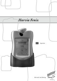
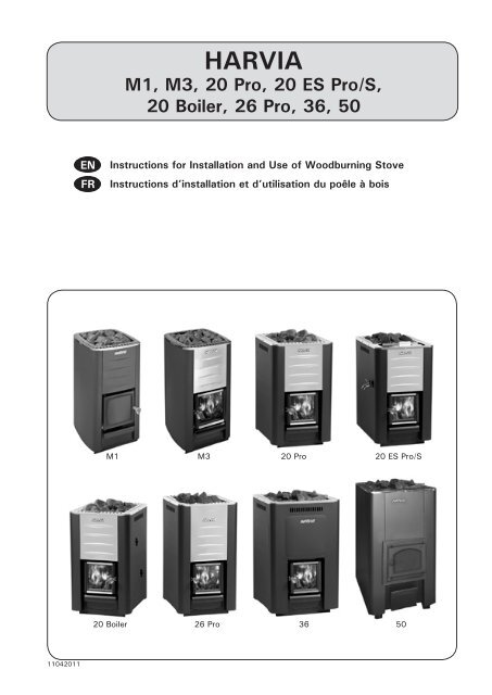
<strong>Instructions</strong> for Installation and Use of Woodburning Stove<br />
<strong>Instructions</strong> d’installation <strong>et</strong> d’utilisation du poêle à bois<br />
M1 M3 20 Pro 20 ES Pro/S<br />
20 Boiler<br />
HARVIA<br />
M1, M3, 20 Pro, 20 ES Pro/S,<br />
20 Boiler, 26 Pro, 36, 50<br />
26 Pro 36 50
Congratulations on your choice! The <strong>Harvia</strong> sauna<br />
stove works best and serves you longest when it<br />
is used and maintained according to these instructions.<br />
Read the instructions carefully before installing or<br />
using the stove. Keep the instructions for future<br />
reference.<br />
ConTEnTS<br />
1. GEnERAL .................................................................... 3<br />
1.1. Technical Data ..................................................... 3<br />
1.2. Stove Parts ......................................................... 4<br />
2. InSTRUCTIonS FoR USE ..............................................4<br />
2.1. Warnings ............................................................ 4<br />
2.2. Preparing the Stove for Use ...................................5<br />
2.3. Burning Material ...................................................5<br />
2.4. Sauna Stones ...................................................... 5<br />
2.5. Heating the Stove ................................................6<br />
2.6. Sauna Water ....................................................... 7<br />
2.7. Maintenance ........................................................ 7<br />
2.8. Troubleshooting ...................................................8<br />
3. SAUnA RooM ............................................................. 9<br />
3.1. Effects that Heating the Stove has on the Sauna<br />
Room ........................................................................ 9<br />
3.2. Ventilation of the Sauna Room ...............................9<br />
3.3. Sauna Room Hygiene ............................................9<br />
4. InSTRUCTIonS FoR InSTALLATIon ............................ 10<br />
4.1. Before Installation .............................................. 10<br />
4.1.1. Protecting the Floor ................................... 10<br />
4.1.2. Saf<strong>et</strong>y Distances ........................................ 11<br />
4.1.3. Protective Covers ....................................... 12<br />
4.1.4. <strong>Harvia</strong> Protective Sheath and Bedding ........... 12<br />
4.2. Installing the Stove ............................................. 13<br />
4.2.1. Adjustable Legs ......................................... 13<br />
4.2.2. Connecting the Stove to a Masonry Flue ....... 13<br />
4.2.3. Connecting the Stove to a <strong>Harvia</strong> Steel<br />
Chimney ............................................................. 15<br />
4.3. Changing the Opening Direction of the Stove Door . 15<br />
4.4. Accessories ....................................................... 16<br />
Félicitations pour c<strong>et</strong> excellent choix ! Le poêle pour<br />
sauna <strong>Harvia</strong> fonctionne de façon optimale <strong>et</strong> durable<br />
dans le cadre d’une utilisation <strong>et</strong> d’un entr<strong>et</strong>ien<br />
conformes aux présentes instructions.<br />
Lisez attentivement les présentes instructions avant<br />
d’installer ou d’utiliser le poêle. Conservez les instructions<br />
pour pouvoir vous y reporter ultérieurement.<br />
TABLE dES MATIéRES<br />
1. GénéRALITéS .............................................................. 3<br />
1.1. Données techniques .............................................3<br />
1.2. Composants du poêle ...........................................4<br />
2. InSTRUCTIonS d’UTILISATIon .....................................4<br />
2.1. Avertissements .................................................... 4<br />
2.2. Préparation du poêle à l’utilisation ..........................4<br />
2.3. Matériau combustible............................................5<br />
2.4. Pierres pour sauna ................................................5<br />
2.5. Chauffage du poêle ..............................................6<br />
2.6. Eau du sauna ....................................................... 7<br />
2.7. Entr<strong>et</strong>ien du poêle ................................................7<br />
2.8. Dépannage .......................................................... 8<br />
3. CABInE dU SAUnA ...................................................... 9<br />
3.1. Eff<strong>et</strong>s du poêle chaud sur la cabine de sauna ...........9<br />
3.2. Ventilation de la cabine de sauna ...........................9<br />
3.3. Hygiène de la cabine de sauna ...............................9<br />
4. InSTRUCTIonS d’InSTALLATIon ................................ 10<br />
4.1. Avant l'installation ............................................. 10<br />
4.1.1. Protection du sol ....................................... 10<br />
4.1.2. Distances de sécurité ................................. 11<br />
4.1.3. Plaques de protection ................................. 12<br />
4.1.4. Gaine <strong>et</strong> couche de protection <strong>Harvia</strong> ........... 12<br />
4.2. Installation du poêle............................................ 13<br />
4.2.1. Pieds réglables du poêle .............................. 13<br />
4.2.2. Raccordement du poêle à une cheminée en<br />
maçonnerie ......................................................... 13<br />
4.2.3. Raccordement du poêle à une cheminée en<br />
acier <strong>Harvia</strong> ........................................................ 15<br />
4.3. Modification du sens d’ouverture de la porte du foyer 15<br />
4.4. Accessoires ....................................................... 16
En FR<br />
1.1. Technical data<br />
1. GEnERAL<br />
Rated output (kW)<br />
Puissance nominale (kW)<br />
Sauna room volume (m³)<br />
Volume de la cabine de sauna (m³)<br />
Required temperature class of chimney<br />
Classe de température requise de la<br />
cheminée<br />
Diam<strong>et</strong>er of connection opening (mm)<br />
Diamètre de l’ouverture de<br />
raccordement (mm)<br />
Stone quantity (max. kg)<br />
Quantité de pierres (max. kg)<br />
Stone size (cm)<br />
Taille des pierres (cm)<br />
Weight (kg)<br />
Poids (kg)<br />
Width (mm)<br />
Largeur (mm)<br />
Depth (mm)<br />
Profondeur (mm)<br />
Height (mm)<br />
Hauteur (mm)<br />
+ adjustable legs (mm)<br />
+ pieds réglables (mm)<br />
Thickness of fire chamber cover (mm)<br />
Épaisseur du couvercle du foyer (mm)<br />
Maximum length of firewood (cm)<br />
Longueur maximale du bois de<br />
chauffage (cm)<br />
Water container volume (l)<br />
Volume du récipient d’eau (l)<br />
M1<br />
WKM11<br />
M3<br />
WKM3<br />
20 Pro<br />
WK200<br />
1. GénéRALITéS<br />
1.1. données techniques<br />
20 ES Pro<br />
WK200ES<br />
20 ES Pro S<br />
WK200ESST<br />
20 Boiler<br />
WK200B<br />
26 Pro<br />
WK260<br />
36<br />
WK360<br />
13 18 18 18 22 30 40<br />
50<br />
WK500<br />
4,5–13 8–20 8–20 8–20 10–26 14–36 20–50<br />
T600 T600 T600 T600 T600 T600 T600<br />
115 115 115 115 115 115 140<br />
30 40 40 40 50 60 120<br />
Ø10–15 Ø10–15 Ø10–15 Ø10–15 Ø10–15 Ø10–15 Ø10–15<br />
45 60 75 65 65 70 160<br />
390 430 430 430 430 510 510<br />
430 510 650 510 510 510 720<br />
710<br />
–<br />
760<br />
0–30<br />
Choose the stove model carefully. A stove with too<br />
low output must be heated longer and more intensely,<br />
which will shorten the stove’s life span.<br />
Please note that non-insulated wall and ceiling<br />
surfaces (such as brick, glass, tile and concr<strong>et</strong>e<br />
surfaces) increase the output requirement of the<br />
stove. For every square m<strong>et</strong>er of such wall and ceiling<br />
surface you should calculate an additional 1.2 m3 volume. If the sauna walls are made of massive log,<br />
the volume must be multiplied by 1.5. Examples:<br />
A 10 m3 sauna room with a brick wall 2 m high<br />
and 2 m wide is equivalent to a sauna room of<br />
approximately 15 m3 .<br />
A 10 m3 sauna room with a glass door is<br />
equivalent to a sauna room of approximately<br />
12 m3 .<br />
A 10 m3 sauna room with massive log walls is<br />
equivalent to a sauna room of approximately<br />
15 m3 •<br />
•<br />
•<br />
.<br />
The dealer or our factory representative can assist<br />
you in choosing the stove if needed. You can also<br />
visit our website www.harviasauna.com for further<br />
d<strong>et</strong>ails.<br />
760<br />
0–30<br />
760<br />
0–30<br />
810<br />
0–30<br />
810<br />
0–30<br />
5 10 10 10 6 6 10<br />
35 39 39 39 39 39 61<br />
– – 20 – – – –<br />
1050<br />
Choisissez soigneusement le modèle de poêle. Un<br />
poêle de puissance trop faible doit être chauffé plus<br />
longtemps <strong>et</strong> de façon plus intense, ce qui réduit sa<br />
durée de vie.<br />
Lors du choix du poêle, notez que les surfaces des<br />
murs <strong>et</strong> du plafond qui ne sont pas isolées (surfaces<br />
en brique, en verre, en tuiles <strong>et</strong> en béton) augmentent<br />
les besoins en termes de puissance. Pour chaque<br />
mètre carré de surface composée de telles matières,<br />
vous devez calculer un volume supplémentaire de<br />
1,2 m³. Si les parois du sauna sont en madriers<br />
massifs, le volume doit être multiplié par 1,5.<br />
Exemples :<br />
• Une cabine de sauna de 10 m³ dotée d’un mur<br />
de brique de 2 m de haut <strong>et</strong> 2 m de large équivaut<br />
à une cabine d’environ 15 m³.<br />
• Une cabine de sauna de 10 m³ dotée d’une porte<br />
en verre équivaut à une cabine d’environ 12 m³.<br />
•<br />
Une cabine de sauna de 10 m³ dotée de parois<br />
en madriers massifs équivaut à une cabine<br />
d’environ 15 m³.<br />
Si nécessaire, le distributeur ou le représentant<br />
d’usine peut vous guider dans le choix de votre<br />
poêle. Pour plus d’informations, vous pouvez<br />
aussi visiter notre site Web à l’adresse<br />
www.harviasauna.com.<br />
–<br />
3
En FR<br />
1.2. Stove Parts<br />
A. Upper connection opening<br />
B. Rear connection opening<br />
C. Soot opening<br />
D. Stove door<br />
E. Ash box<br />
Figure 1. Stove parts<br />
Figure 1. Composants du poêle<br />
4<br />
D<br />
E<br />
2. InSTRUCTIonS FoR USE<br />
C<br />
Read the instructions carefully before using<br />
the stove.<br />
2.1. Warnings<br />
• Staying in the hot sauna for long periods of<br />
time makes the body temperature rise, which<br />
may be dangerous.<br />
• Keep away from the stove when it is hot. The<br />
stones and outer surface of the stove may burn<br />
your skin.<br />
• never throw water on the stones when there are<br />
people near the stove, because hot steam may<br />
burn their skin.<br />
• Keep children away from the stove.<br />
• do not l<strong>et</strong> young, handicapped or ill people<br />
bathe in the sauna on their own.<br />
• Consult your doctor about any health-related<br />
limitations to bathing.<br />
• Consult your child welfare clinic about taking<br />
little babies to the sauna.<br />
• Be very careful when moving in the sauna, as<br />
the platform and floors may be slippery.<br />
• never go to a hot sauna if you have taken<br />
alcohol, strong medicines or narcotics.<br />
• never sleep in a hot sauna.<br />
• Sea air and a humid climate may corrode the<br />
m<strong>et</strong>al surfaces of the stove.<br />
• do not hang clothes to dry in the sauna, as this<br />
may cause a risk of fire.<br />
A<br />
1.2. Composants du poêle<br />
A. Ouverture de raccordement supérieure<br />
B. Ouverture de raccordement arrière<br />
C. Ouverture de ramonage<br />
D. Porte du foyer<br />
E. Bac à cendres<br />
B<br />
2. InSTRUCTIonS d’UTILISATIon<br />
Lisez attentivement les présentes instructions<br />
avant d’utiliser le poêle.<br />
2.1. Avertissements<br />
• des séances prolongées dans un sauna chaud<br />
provoquent une élévation de la température du<br />
corps qui peut s’avérer dangereuse.<br />
• Se tenir éloigné des pierres <strong>et</strong> les parties métalliques<br />
du poêle. Elles risquent de provoquer des<br />
brûlures.<br />
• Veiller aussi à ne pas proj<strong>et</strong>er d’eau sur les<br />
pierres lorsque quelqu’un se trouve à proximité<br />
du poêle, la vapeur bouillante risquant de causer<br />
des brûlures.<br />
• Tenir les enfants éloignés du poêle.<br />
• Les enfants, les handicapés <strong>et</strong> les personnes<br />
affaiblies ou en mauvaise santé doivent être<br />
accompagnés lors des séances de sauna.<br />
• Il est conseillé de consulter un médecin au cas où<br />
les séances de sauna seraient contre-indiquées.<br />
• discuter avec un pédiatre de la participation éventuelle<br />
d’enfants en bas âge aux séances de sauna.<br />
• Toujours se déplacer avec la plus grande prudence,<br />
les bancs <strong>et</strong> le sol pouvant être glissants.<br />
• ne pas prendre un sauna sous l’eff<strong>et</strong> de produits<br />
narcotiques (alcool, médicaments, drogues <strong>et</strong>c.).<br />
• ne jamais dormir dans un sauna chaud.<br />
• L’air marin <strong>et</strong> humide est susceptible d’avoir une<br />
action corrosive sur les surfaces métalliques.<br />
•<br />
ne pas utiliser le sauna pour y faire sécher du<br />
linge sous peine de provoquer un incendie.
En FR<br />
2.2. Preparing the Stove for Use<br />
Perform the first heating outdoors or in a wellventilated<br />
room. The stove body has been painted<br />
with protective paint, which will vaporise during<br />
the first heating. This will cause the stove body to<br />
emit smoke. When the smoking stops, the stove is<br />
ready for normal use.<br />
If the first heating is done outdoors, install the<br />
smoke pipes ( 4.4.) for draught. This will cause<br />
odours to vaporize from the smoke pipes as well.<br />
The outer casing has been painted with heatresistant<br />
paint, which reaches its final cured state<br />
during the first heating. Prior to this, rubbing or<br />
sweeping the painted surfaces of the stove must<br />
be avoided.<br />
• one load of wood is sufficient for the first<br />
heating.<br />
• The sauna stones should not be placed in the<br />
stove before the first heating. Place the stones<br />
in the stove only when the stove has cooled<br />
compl<strong>et</strong>ely after the first heating.<br />
do not throw water on the stove during first<br />
heating. Painted surfaces can g<strong>et</strong> damaged.<br />
2.3. Burning Material<br />
Dry wood is the best material for heating the stove.<br />
Dry chopped firewood clinks when it is knocked<br />
tog<strong>et</strong>her with another piece. The moisture of<br />
the wood has a significant impact on how clean<br />
the burning is as well as on the efficiency of the<br />
stove. You can start the fire with birch bark or<br />
newspapers.<br />
The thermal value of wood differs from one type<br />
of wood to another. For example, you must burn<br />
15 % less beech than birch to obtain the same heat<br />
quantity. If you burn large amounts of wood, which<br />
has a high thermal value, the life span of the stove<br />
will shorten!<br />
Keep the burning material in a separate storage<br />
area. You can keep a small amount of burning<br />
material in the vicinity of the stove as long as its<br />
temperature does not exceed 80 °C.<br />
do not burn the following materials in the stove:<br />
• Burning materials that have a high thermal<br />
value (such as chipboard, plastic, coal,<br />
brick<strong>et</strong>s, pell<strong>et</strong>s)<br />
• Painted or impregnated wood<br />
• Waste (such as PVC plastic, textiles, leather,<br />
rubber, disposable diapers)<br />
• Garden waste (such as grass, leaves)<br />
2.4. Sauna Stones<br />
• The stones should be 10–15 cm in diam<strong>et</strong>er.<br />
• Only proper stones meant for the specific<br />
purpose should be used as sauna stones.<br />
Peridotite, olivine-dolerite and olivine are<br />
suitable stone types. Stones found in nature<br />
may contain harmful substances, such as iron<br />
pyrite, and therefore should not be used.<br />
• Wash off dust from the stones before piling<br />
them into the stove.<br />
• Place the larger stones at the bottom and the<br />
smaller ones on the top.<br />
2.2. Préparation du poêle à l’utilisation<br />
Procédez à la première utilisation à l’extérieur ou<br />
dans une pièce bien ventilée. Le corps du poêle<br />
est recouvert d’une peinture de protection qui va<br />
s’évaporer à la première utilisation, entraînant un<br />
dégagement de fumée. Une fois la fumée dissipée,<br />
le poêle est prêt pour une utilisation normale.<br />
Si vous l’effectuez à l’extérieur, installez les<br />
conduits de fumée ( 4.4.) pour tirage. De c<strong>et</strong>te manière,<br />
les conduits de fumée diffuseront également<br />
des odeurs.<br />
L’enveloppe des poêles est recouverte d’une peinture<br />
résistante à la chaleur, qui atteint son état durci<br />
final lors de la première mise en service. Avant cela,<br />
vous devez éviter de frotter ou d’essuyer les surfaces<br />
peintes du poêle.<br />
• Une charge de bois suffit à la première mise en<br />
service.<br />
• Les pierres du poêle ne doivent pas être placées<br />
dans le poêle avant la première utilisation.<br />
ne placez les pierres dans le poêle que lorsque<br />
ce dernier a complètement refroidi après la<br />
première utilisation.<br />
ne j<strong>et</strong>ez pas d’eau sur le poêle lors de la première<br />
utilisation, sous peine d’endommager les<br />
surfaces peintes.<br />
2.3. Matériau combustible<br />
Le bois sec est le meilleur matériau de chauffage<br />
du poêle. S’ils sont secs, les morceaux de bois de<br />
chauffage résonnent lorsqu’ils s’entrechoquent.<br />
L’humidité du bois a une incidence importante sur<br />
la propr<strong>et</strong>é de la combustion <strong>et</strong> l’efficacité du poêle.<br />
Vous pouvez allumer le feu à l’aide d’écorce de<br />
bouleau ou de journaux.<br />
La valeur thermique du bois diffère selon la nature<br />
de ce dernier. Ainsi, par exemple, il faut brûler 15 %<br />
de hêtre en moins que de bouleau pour obtenir la<br />
même quantité de chaleur. Le fait de brûler de grosses<br />
quantités de bois présentant une forte valeur<br />
thermique réduit la durée de vie du poêle !<br />
Stockez le matériau combustible dans un lieu à<br />
part. Vous pouvez en conserver une p<strong>et</strong>ite quantité<br />
à proximité du poêle, à condition que la température<br />
de ce dernier ne dépasse pas 80 °C.<br />
dans le poêle, ne brûlez pas les matériaux suivants :<br />
• les matériaux combustibles ayant un pouvoir<br />
calorifique élevé (copeaux de bois, plastique,<br />
charbon, briqu<strong>et</strong>tes, pal<strong>et</strong>tes)<br />
• le bois peint ou imprégné<br />
• les déch<strong>et</strong>s (comme le plastique PVC, les textiles,<br />
le cuir, le caoutchouc, les couches j<strong>et</strong>ables)<br />
• les résidus de jardin (comme l’herbe <strong>et</strong> les feuilles)<br />
2.4. Pierres pour sauna<br />
• Le diamètre des pierres doit se situer entre 5 <strong>et</strong><br />
10 cm.<br />
• Seules des pierres adaptées à c<strong>et</strong> usage spécifique<br />
doivent être utilisées en tant que pierres<br />
de sauna. La péridotite, l’olivine <strong>et</strong> la dolérite<br />
olivine sont des pierres adaptées. Les roches<br />
supracrustales trouvées dans la nature peuvent<br />
contenir des substances nocives, par exemple<br />
de la pyrite <strong>et</strong> ne doivent donc pas être utilisées.<br />
•<br />
Dépoussiérer les pierres avant de les empiler<br />
5
En FR<br />
•<br />
•<br />
•<br />
6<br />
Make sure that air circulates b<strong>et</strong>ween the<br />
stones.<br />
do not place stones against the frame around<br />
the stone space or on top of it.<br />
do not place stones b<strong>et</strong>ween the grille and the<br />
stove body!<br />
Perform the first heating<br />
outdoors or in a well-ventilated<br />
room.<br />
Procédez à la première<br />
utilisation à l’extérieur ou dans<br />
une pièce bien ventilée.<br />
Figure 2. Preparing the stove and piling the stones<br />
Figure 2. Préparation du poêle <strong>et</strong> empilement des pierres<br />
2.5. Heating the Stove<br />
Before heating the stove make sure that there<br />
are no unnecessary items in the sauna or<br />
inside the stove's saf<strong>et</strong>y distances.<br />
1.<br />
2.<br />
3.<br />
4.<br />
5.<br />
Empty the ash box.<br />
Place the firewood into the fire chamber,<br />
leaving enough room for the combustion air to<br />
flow b<strong>et</strong>ween the firewood. Place the biggest<br />
firewood on the bottom and the smaller ones<br />
on the top. Use firewood with a diam<strong>et</strong>er of<br />
8–12 cm. Fill ca 2/3 of the fire chamber with<br />
firewood (consider the thermal value of wood,<br />
2.3.).<br />
Place the kindling on the top of the firewood.<br />
By starting the fire on the top of the firewood,<br />
fewer emissions are produced.<br />
Fire the kindling and close the door. The<br />
amount of draught can be adjusted by opening<br />
the ash box.<br />
- When heating the stove, it is generally a<br />
good idea to at first keep the ash box slightly<br />
open. This ensures that the fire starts burning<br />
properly.<br />
- Excessive draught will cause the stove body<br />
to become red-heated, which will shorten its<br />
life span considerably.<br />
- During bathing, and when the sauna room<br />
is already heated, the ash box can be closed<br />
to keep down the fire and decrease wood<br />
consumption.<br />
If necessary, place more firewood into the<br />
fire chamber when the ember is dying down.<br />
Use firewood with a diam<strong>et</strong>er of 12–15 cm.<br />
It takes only a couple of pieces of wood to<br />
•<br />
•<br />
•<br />
•<br />
dans le poêle.<br />
Placez les plus grosses pierres au fond <strong>et</strong> les<br />
plus p<strong>et</strong>ites sur le dessus.<br />
Les pierres ne doivent pas former une pile trop<br />
serrée, pour perm<strong>et</strong>tre à l’air de circuler à travers<br />
le poêle.<br />
ne placez pas les pierres contre la grille, autour<br />
du compartiment à pierres ou au-dessus.<br />
ne placez pas de pierres entre la grille <strong>et</strong> le<br />
corps du poêle !<br />
Place the stones in the stove only when the stove has cooled compl<strong>et</strong>ely.<br />
Ne placez les pierres dans le poêle que lorsque ce dernier a complètement<br />
refroidi après la première utilisation.<br />
2.5. Chauffage du poêle<br />
Avant de chauffer le poêle, vérifiez qu’aucun<br />
obj<strong>et</strong> inutile ne se trouve dans le sauna ou<br />
dans le périmètre de sécurité du poêle.<br />
1.<br />
2.<br />
3.<br />
4.<br />
5.<br />
Videz le bac à cendres.<br />
Placez le bois de chauffage dans le foyer en<br />
laissant suffisamment de place pour que l'air<br />
comburant puisse circuler entre les morceaux.<br />
Placez les plus grosses pierres au fond <strong>et</strong> les<br />
plus p<strong>et</strong>ites sur le dessus. Utilisez du bois de<br />
chauffage d'un diamètre compris entre 8 <strong>et</strong><br />
12 cm. Remplissez le foyer environ aux deux<br />
tiers de bois de chauffage (en tenant compte<br />
de la valeur thermique du bois, 2.3.).<br />
Placez le bois d'allumage sur le bois de chauffage.<br />
Le fait d'allumer le feu sur le bois de<br />
chauffage réduit la production d'émissions.<br />
Allumez le bois de chauffage <strong>et</strong> fermez la<br />
porte. Le tirage peut être réglé en ouvrant le<br />
bac de cendres.<br />
- Lorsque vous chauffez le poêle, nous vous<br />
conseillons de commencer par laisser le bac à<br />
cendres légèrement ouvert. Cela vous perm<strong>et</strong><br />
de démarrer correctement le feu.<br />
- Un tirage excessif risque de porter le poêle au<br />
rouge <strong>et</strong> de réduire ainsi considérablement sa<br />
durée de vie.<br />
- Lors des séances de sauna <strong>et</strong> lorsque la<br />
cabine est déjà chauffée, vous pouvez fermer<br />
le bac à cendres afin de baisser le feu <strong>et</strong> de<br />
réduire la consommation de bois.<br />
Si nécessaire, placez davantage de bois de<br />
chauffage dans le foyer lorsque la braise diminue.<br />
Utilisez du bois de chauffage d'un diamè-
En FR<br />
•<br />
•<br />
•<br />
maintain the bathing temperature.<br />
Prolonged, intense heating may cause risk<br />
of fire!<br />
Excessive heating (several full loads in a row,<br />
for example) will make the stove and the<br />
chimney overheat. Overheating shortens the<br />
stove’s life span and may cause risk of fire.<br />
A good rule of thumb is that temperatures of<br />
over 100 ºC are too high in a sauna.<br />
Observe the correct wood quantities noted in<br />
the heating instructions. L<strong>et</strong> the stove, chimney<br />
and sauna room cool down if necessary.<br />
2.6. Sauna Water<br />
The water that is thrown on the stones should be<br />
clean household water. Make sure the water is of<br />
high enough quality, because water containing salt,<br />
lime, iron or humus may prematurely corrode the<br />
stove. Especially seawater will corrode the stove<br />
very rapidly. The following quality requirements<br />
apply to household water:<br />
• humus content
En FR<br />
2.8. Troubleshooting<br />
There is no draught in the flue. Smoke comes into<br />
the sauna.<br />
• There are leaks in the flue connection. Seal the<br />
connection ( 4.2.2.).<br />
• The brick flue is cold.<br />
• There is low pressure caused by an extractor<br />
fan or another device in the room. Make sure<br />
there is enough air to compensate.<br />
• Several fireplaces are used at the same time.<br />
Make sure there is enough air to compensate.<br />
• The ash box is full.<br />
• The smoke canals of the stove are blocked<br />
( 2.7.).<br />
• The flue connection pipe is too deep in the<br />
chimney ( 4.2.2.).<br />
The sauna does not heat up.<br />
•<br />
•<br />
•<br />
•<br />
•<br />
8<br />
The sauna is too big in relation to the stove’s<br />
heating capacity ( 1.1.).<br />
There is lots of non-insulated wall surface in<br />
the sauna ( 1.1.).<br />
The burning material is moist or its quality is<br />
otherwise low ( 2.3.).<br />
The flue does not have a good draught.<br />
The smoke canals of the stove are blocked<br />
( 2.7.).<br />
The stove stones do not heat up.<br />
•<br />
•<br />
•<br />
•<br />
•<br />
The sauna is too small in relation to the stove’s<br />
heating capacity ( 1.1.).<br />
The flue does not have a good draught.<br />
The burning material is moist or its quality is<br />
otherwise low ( 2.3.).<br />
The smoke canals of the stove are blocked<br />
( 2.7.).<br />
Check the stone placement ( 2.4.). Remove the<br />
small pieces of stone and stones that are less<br />
than 10 cm in diam<strong>et</strong>er from the stone space.<br />
Replace the disintegrated stones with large and<br />
undamaged ones.<br />
The stove emits smell.<br />
•<br />
•<br />
See section 2.2.<br />
The hot stove may emphasize odours mixed in<br />
the air that are not, however, caused by the<br />
sauna or the stove. Examples: paint, glue, oil,<br />
seasoning.<br />
2.8. dépannage<br />
Absence de tirage dans le conduit de fumée. de la<br />
fumée s’échappe dans le sauna.<br />
• Le raccordement du conduit présente des fuites.<br />
Imperméabilisez le raccordement ( 4.2.2.).<br />
• Le conduit en brique est froid.<br />
• La pression est faible en raison d’un évacuateur<br />
des fumées ou d’un autre dispositif dans<br />
la pièce. Assurez-vous qu’il y ait suffisamment<br />
d’air pour compenser.<br />
• Plusieurs foyers sont utilisés simultanément.<br />
Assurez-vous qu’il y ait suffisamment d’air<br />
pour compenser.<br />
• Le bac à cendres est plein.<br />
• Les conduits de fumée du poêle sont obstrués<br />
( 2.7.).<br />
• Le conduit de fumée de raccordement est trop<br />
loin dans le conduit ( 4.2.2.).<br />
Le sauna ne chauffe pas.<br />
•<br />
•<br />
•<br />
•<br />
•<br />
Le sauna est trop grand par rapport à la capacité<br />
de chauffage du poêle ( 1.1.).<br />
Le sauna comporte de nombreuses surfaces de<br />
parois non isolées ( 1.1.).<br />
Le matériau combustible est humide ou de<br />
mauvaise qualité ( 2.3.).<br />
Le conduit ne présente pas un bon tirage.<br />
Les conduits de fumée du poêle sont obstrués<br />
( 2.7.).<br />
Les pierres du poêle ne chauffent pas.<br />
•<br />
•<br />
•<br />
•<br />
•<br />
Le sauna est trop p<strong>et</strong>it par rapport à la capacité<br />
de chauffage du poêle (1.1.).<br />
Le conduit ne présente pas un bon tirage.<br />
Le matériau combustible est humide ou de<br />
mauvaise qualité.<br />
Les conduits de fumée du poêle sont obstrués<br />
( 2.7.).<br />
Vérifiez si les pierres sont correctement mises<br />
en place (2.4.). R<strong>et</strong>irez du compartiment à pierres<br />
les p<strong>et</strong>its morceaux de pierre <strong>et</strong> les pierres<br />
présentant un diamètre inférieur à 10 cm. Remplacez<br />
les pierres désintégrées par des neuves<br />
de grande taille.<br />
des odeurs se dégagent du poêle.<br />
•<br />
•<br />
Voir le paragraphe 2.2.<br />
Lorsqu’il est chaud, le poêle peut accentuer les<br />
odeurs présentes dans l’air mais qui ne sont<br />
pas liées au sauna ni au poêle. Exemples : peinture,<br />
colle, graisse, assaisonnements.
En FR<br />
3. SAUnA RooM<br />
3.1. Effects that Heating the Stove has on<br />
the Sauna Room<br />
Light-coloured floor materials will become dirty from<br />
the ash, particles of stone and m<strong>et</strong>al flakes that fall<br />
from the stove. Use floor coverings made of dark<br />
materials and dark joint grouts.<br />
It is perfectly normal for the wooden surfaces of<br />
the sauna room to blacken in time. The blackening<br />
may be accelerated by<br />
•<br />
•<br />
•<br />
•<br />
•<br />
sunlight<br />
heat from the stove<br />
protective agents on the walls (protective<br />
agents have a poor heat resistance level)<br />
fine particles disintegrating from the sauna<br />
stones which rise with the air flow<br />
smoke that enters the sauna, for example,<br />
when adding firewood.<br />
When installation instructions given by the<br />
manufacturer are followed, the stove will not<br />
heat the inflammable material in sauna room to a<br />
dangerous level.<br />
3.2. Ventilation of the Sauna Room<br />
Gravity exhaust ventilation (figure 3)<br />
A. The fresh air inl<strong>et</strong> must be placed close to the<br />
floor near the stove and<br />
B. its outl<strong>et</strong> should be as far as possible from the<br />
stove and near the ceiling. The stove itself<br />
circulates air effectively; the purpose of the<br />
outl<strong>et</strong> is mainly to remove moisture from the<br />
sauna after bathing.<br />
Mechanical exhaust ventilation (figure 4)<br />
A. The fresh air inl<strong>et</strong> must be approx. 500 mm<br />
above the stove and<br />
B. the outl<strong>et</strong> should be close to the floor, for<br />
example, below the bench.<br />
3.3. Sauna Room Hygiene<br />
Bench towels should be used during bathing to<br />
prevent sweat from g<strong>et</strong>ting onto the benches.<br />
The benches, walls and floor of the sauna should<br />
be washed thoroughly at least every six months.<br />
Use a scrubbing brush and sauna d<strong>et</strong>ergent.<br />
A Ø50–100<br />
Figure 3. Gravity exhaust ventilation<br />
Figure 3. Ventilation par gravité<br />
B<br />
3. CABInE dU SAUnA<br />
3.1. Eff<strong>et</strong>s du poêle chaud sur la cabine de<br />
sauna<br />
Les sols de couleur claire seront salis par les cendres,<br />
les particules de pierre <strong>et</strong> les paill<strong>et</strong>tes de métal<br />
qui tombent du poêle. Utilisez des revêtements de<br />
sol <strong>et</strong> des joints en ciment sombres.<br />
Avec le temps, il est tout à fait normal que les<br />
surfaces en bois de la cabine de sauna noircissent.<br />
Ce noircissement peut être accéléré par :<br />
•<br />
•<br />
•<br />
•<br />
•<br />
la lumière du soleil<br />
la chaleur du poêle<br />
les agents de protection appliqués sur les murs<br />
(les agents de protection présentent un faible<br />
niveau de résistance à la chaleur)<br />
les fines particules provenant des pierres du<br />
poêle qui sont soulevées par le flux d'air<br />
la fumée qui se dégage dans le sauna, par<br />
exemple, lors de l'ajout de bois de chauffage.<br />
Lorsque les instructions d’installation fournies par le<br />
fabricant sont respectées, le poêle ne chauffe pas le matériau<br />
combustible du sauna à un niveau dangereux.<br />
3.2. Ventilation de la cabine de sauna<br />
Ventilation par gravité (figure 3)<br />
A. La prise d'air neuf doit être placée à proximité<br />
du sol, près du poêle, <strong>et</strong><br />
B. sa sortie doit être située aussi loin que possible<br />
du poêle <strong>et</strong> à proximité du toit. Le poêle luimême<br />
fait circuler l’air efficacement ; l'ouverture<br />
sert principalement à évacuer l'humidité de<br />
la cabine après la séance de sauna.<br />
Ventilation mécanique (figure 4)<br />
A. La prise d'air neuf doit être placée à environ<br />
500 mm au-dessus du poêle <strong>et</strong><br />
B. la sortie doit être placée à proximité du sol, par<br />
exemple sous le banc.<br />
3.3. Hygiène de la cabine de sauna<br />
Utiliser des servi<strong>et</strong>tes pour banc pendant la séance<br />
de sauna, pour éviter que la transpiration ne coule<br />
sur les banqu<strong>et</strong>tes.<br />
Les banqu<strong>et</strong>tes, les murs <strong>et</strong> le sol du sauna doivent<br />
être soigneusement lavés au moins tous les six<br />
mois. Utiliser une brosse à récurer <strong>et</strong> du détergent<br />
pour sauna.<br />
500 A Ø50–100<br />
Figure 4. Mechanical exhaust ventilation<br />
Figure 4. Ventilation mécanique<br />
B<br />
9
En FR<br />
4. InSTRUCTIonS FoR InSTALLATIon<br />
4.1. Before Installation<br />
Before installing the stove make sure that all<br />
saf<strong>et</strong>y distance requirements are fulfilled.<br />
There shall be no electrical devices, wires or<br />
inflammable materials within the established saf<strong>et</strong>y<br />
distances around the stove.<br />
• If the saf<strong>et</strong>y distance requirements are not<br />
fulfilled, you should use additional protection<br />
( 4.1.3., 4.1.4.).<br />
• The local fire authorities in charge of approving<br />
the installations can provide more d<strong>et</strong>ailed<br />
information about fire saf<strong>et</strong>y regulations.<br />
4.1.1. Protecting the Floor<br />
See figure 5.<br />
A. Concr<strong>et</strong>e floor without tiles. The stove can<br />
be installed on a concr<strong>et</strong>e floor without any<br />
specific saf<strong>et</strong>y measures, if the concr<strong>et</strong>e is at<br />
least 60 mm thick. Make sure that there are no<br />
wires or water pipes in the concr<strong>et</strong>e cast below<br />
the stove.<br />
B. Floor made of inflammable material. Protect<br />
the floor with at least 60 mm thick slab of<br />
concr<strong>et</strong>e. The slab must extend to a distance<br />
of 300 mm from the stove on the sides and<br />
behind (unless the stove is next to a wall) and<br />
at least 400 mm in front of the stove. The slab<br />
should be supported slightly above the floor<br />
surface to keep the floor material dry. You<br />
can also use the <strong>Harvia</strong> protective sheath and<br />
bedding ( 4.1.4.).<br />
C. Tile floor. The floor glues and plasters and<br />
waterproof materials used below the tiles are<br />
not resistant to the heat radiation of the stove.<br />
Protect the floor with the <strong>Harvia</strong> protective<br />
bedding ( 4.1.4.) or similar heat radiation<br />
protection.<br />
Figure 5. Protecting the floor (all dimensions in millim<strong>et</strong>ers)<br />
Figure 5. Protection du sol (toutes les dimensions sont fournies en millimètres)<br />
10<br />
4. InSTRUCTIonS d’InSTALLATIon<br />
4.1. Avant l'installation<br />
Avant d'installer le poêle, vérifiez que toutes<br />
les distances de sécurité sont respectées.<br />
Aucun appareil électrique, câble ou matériau inflammable<br />
ne doit se trouver dans le périmètre de sécurité<br />
établi autour du poêle.<br />
• Si les distances de sécurité ne sont pas respectées,<br />
vous devez installer une protection supplémentaire<br />
( 4.1.3., 4.1.4.).<br />
• Les autorités locales de lutte contre l’incendie<br />
chargées d’approuver les installations peuvent<br />
vous fournir de plus amples informations sur<br />
les réglementations de sécurité contre l’incendie.<br />
4.1.1. Protection du sol<br />
Voir figure 5.<br />
A. Sol en béton sans carrelage : le poêle peut être<br />
installé sur un sol en béton sans mesure de<br />
sécurité spécifique si le béton mesure au moins<br />
60 mm d’épaisseur. Assurez-vous qu’aucun<br />
câble électrique ni aucun tuyau d’eau ne se<br />
trouve dans le béton situé sous le poêle.<br />
B. Sol constitué de matériaux inflammables :<br />
protégez le sol avec une dalle de béton d'une<br />
épaisseur minimale de 60 mm. La dalle doit<br />
dépasser de 300 mm sur les côtés <strong>et</strong> à l'arrière<br />
du corps du poêle (sauf si le poêle est<br />
placé près d'un mur), <strong>et</strong> d'au moins 400 mm à<br />
l'avant. La dalle doit être maintenue légèrement<br />
au-dessus de la surface du sol, afin de maintenir<br />
le sol au sec. Vous pouvez aussi utiliser<br />
la gaine <strong>et</strong> la couche de protection <strong>Harvia</strong> (<br />
4.1.4.).<br />
C.<br />
Sol en carrelage : les colles <strong>et</strong> enduits de sol <strong>et</strong><br />
les matériaux d'étanchéité utilisés sous les carreaux<br />
ne résistent pas au rayonnement de chaleur<br />
du poêle. Protégez le sol avec la couche de<br />
protection <strong>Harvia</strong> ( 4.1.4.) ou une protection<br />
similaire contre le rayonnement de chaleur.
En FR<br />
4.1.2. Saf<strong>et</strong>y distances<br />
See figure 6.<br />
A. Ceiling. The minimum saf<strong>et</strong>y distance b<strong>et</strong>ween<br />
the stove and the ceiling is 1200 mm.<br />
B. Masonry walls. Leave 50 mm b<strong>et</strong>ween the<br />
stove and walls, provided that the air can<br />
circulate in front and to one side of the stove.<br />
If the stove is installed in a recessed wall, leave<br />
100 mm b<strong>et</strong>ween the stove and walls for the<br />
air circulation.<br />
C. Walls and benches made of inflammable<br />
materials. The minimum saf<strong>et</strong>y distances to<br />
inflammable materials: 500 mm on either side<br />
and behind the stove, 500 mm in the front.<br />
d. Space required for use and maintenance. The<br />
stove user needs at least one square m<strong>et</strong>re of<br />
space in front of the stove.<br />
min.<br />
50<br />
B<br />
A<br />
C<br />
min.<br />
50<br />
D<br />
min.<br />
500<br />
min. 1200<br />
min.<br />
100<br />
B<br />
min.<br />
50<br />
min.<br />
100<br />
Figure 6. Saf<strong>et</strong>y distances (all dimensions in millim<strong>et</strong>ers)<br />
Figure 6. Distances de sécurité (toutes les dimensions sont fournies en millimètres)<br />
4.1.2. distances de sécurité<br />
Voir figure 6.<br />
A. Toit : la distance de sécurité minimale entre le<br />
poêle <strong>et</strong> le toit est de 1 200 mm.<br />
B. Murs maçonnés : laissez 50 mm entre le poêle<br />
<strong>et</strong> les murs, à condition que l’air puisse circuler<br />
à l’avant <strong>et</strong> sur un côté du poêle. Si le poêle<br />
est encastré dans un mur, laissez 100 mm<br />
entre le poêle <strong>et</strong> les parois afin de perm<strong>et</strong>tre à<br />
l’air de circuler.<br />
C. Murs <strong>et</strong> plates-formes en bois : les distances de<br />
sécurité minimales par rapport aux matériaux<br />
inflammables sont de 500 mm d’un des côtés<br />
du poêle <strong>et</strong> à l’arrière, <strong>et</strong> de 500 mm à l’avant.<br />
d. Espace requis pour l’utilisation <strong>et</strong> l’entr<strong>et</strong>ien :<br />
l’utilisateur doit disposer d’au moins 1 m² d’espace<br />
libre devant le poêle.<br />
min.<br />
100<br />
min.<br />
500<br />
min.<br />
500<br />
min.<br />
500<br />
D D<br />
C<br />
C<br />
min.<br />
500<br />
min.<br />
500<br />
C<br />
11
En FR<br />
4.1.3. Protective Covers<br />
See figure 7. The specified saf<strong>et</strong>y distances from<br />
inflammable materials can be reduced to half with<br />
a single protective cover and to one-fourth with a<br />
double protective cover.<br />
• A single protective cover (1x) can be made of<br />
non-flammable fibre-reinforced concr<strong>et</strong>e plate<br />
(mineral plate) with a minimum thickness of<br />
7 mm or of a m<strong>et</strong>al she<strong>et</strong> with a minimum<br />
thickness of 1 mm.<br />
• A double protective cover (2x) can be made of<br />
two of the plates mentioned above.<br />
• Fixing points must be placed close enough to<br />
one another to ensure a sturdy structure.<br />
• Leave at least 30 mm space b<strong>et</strong>ween the<br />
surface to be protected and the plate/s.<br />
• The protective cover should extend at least<br />
600 mm higher than the top surface of the stove.<br />
• A masonry wall at least 55 mm thick is the<br />
equivalent of a single protective cover. A<br />
masonry wall at least 110 mm thick is the<br />
equivalent of a double protective cover. The<br />
masonry should be open from the sides and<br />
at least 30 mm away from the surface to be<br />
protected.<br />
A<br />
B<br />
A B<br />
A B<br />
1x min. 250 min. 500<br />
2x min. 125 min. 500<br />
min. 30<br />
min. 30<br />
min. 30<br />
Figure 7. Protective covers (all dimensions in millim<strong>et</strong>ers)<br />
Figure 7. Plaques de protection (toutes les dimensions sont fournies en millimètres)<br />
4.1.4. <strong>Harvia</strong> Protective Sheath and Bedding<br />
See figure 8. The <strong>Harvia</strong> protective sheath and bedding<br />
provide an easy way to protect the inflammable<br />
materials from the heat of the stove. (For models<br />
M1, M3, 20 Pro, 20 ES Pro/S and 26 Pro only.)<br />
min. 110<br />
min. 50<br />
min. 125<br />
min. 50<br />
4.1.3. Plaques de protection<br />
Voir figure 7. Les distances de sécurité spécifiées<br />
pour les matériaux combustibles peuvent être réduites<br />
de moitié si vous utilisez une plaque de protection<br />
simple <strong>et</strong> d’un quart si vous utilisez une plaque<br />
de protection double.<br />
• Une plaque de protection simple (1x) peut être<br />
constituée d’une plaque de ciment renforcé de<br />
fibres non combustible (plaque minérale) d’une<br />
épaisseur minimale de 7 mm ou d’une feuille de<br />
métal d’une épaisseur minimale de 1 mm.<br />
• Une plaque de protection double (2x) peut être<br />
constituée de deux plaques décrites ci-dessus.<br />
• Les points de fixation doivent être suffisamment<br />
proches les uns des autres pour garantir<br />
la solidité de la structure.<br />
• Laissez au moins 30 mm d’espace entre la surface<br />
à protéger <strong>et</strong> la ou les plaques.<br />
• La plaque de protection doit dépasser d’au<br />
moins 600 mm au-dessus de la surface supérieure<br />
du poêle.<br />
• Un mur maçonné d’une épaisseur minimale<br />
de 55 mm équivaut à une plaque de protection<br />
simple. Un mur maçonné d’une épaisseur<br />
minimale de 110 mm équivaut à une plaque de<br />
protection double. Le mur maçonné doit être<br />
ouvert sur les côtés <strong>et</strong> se trouver à au moins<br />
30 mm de la surface à protéger.<br />
min. 600<br />
Figure 8. <strong>Harvia</strong> protective sheath and bedding (all dimensions in millim<strong>et</strong>ers)<br />
Figure 8. Gaine <strong>et</strong> couche de protection <strong>Harvia</strong> (toutes les dimensions sont fournies en millimètres)<br />
12<br />
1x<br />
2x<br />
4.1.4. Gaine <strong>et</strong> couche de protection <strong>Harvia</strong><br />
Voir figure 8. La gaine <strong>et</strong> la couche de protection<br />
<strong>Harvia</strong> offrent une solution simple pour protéger les<br />
matériaux combustibles de la chaleur du poêle. (Modèles<br />
: M1, M3, 20 Pro, 20 ES Pro/S, 26 Pro.)<br />
850<br />
770<br />
560<br />
615<br />
1010<br />
220<br />
48–65<br />
665<br />
470
En FR<br />
4.2. Installing the Stove<br />
4.2.1. Adjustable Legs<br />
(Models 20 Pro, 20 ES Pro/S, 20 Boiler, 26 Pro and<br />
36 only.) The adjustable legs enable the stove to be<br />
installed firmly on an inclined floor. The adjustable<br />
range is 0–30 mm. Unscrew the adjustable fe<strong>et</strong> to<br />
an extent that allows them to be adjusted using a<br />
wrench (17 mm) when the stove is in position.<br />
note! The adjustable fe<strong>et</strong> could scratch the floor<br />
surface if the stove is moved on the floor.<br />
4.2.2. Connecting the Stove to a Masonry Flue<br />
Make an opening in the fireproof wall for the flue<br />
connection. Notice that the opening has to be at the<br />
correct height, if you intend to use, for instance, a<br />
protective bedding. The hole should be slightly larger<br />
than the flue connecting pipe. A suitable gap around<br />
the connection pipe is ca. 10 mm. It is advisable to<br />
round off the inner corners of the flue opening to<br />
ensure that the combustion gases can flow freely<br />
to the flue. Additional accessories are available to<br />
make the installation easier ( 4.4.).<br />
Connecting the stove to a masonry flue via the<br />
rear connection opening (figure 9)<br />
1. Bend the cover hatch downwards (M1/M3<br />
only). Attach the flue connection pipe (in the<br />
package) to the rear connection opening so<br />
that the side with a depression faces upwards.<br />
Ensure that the pipe fits tightly in place. If<br />
necessary, hit it gently with a hammer.<br />
2. If the pipe cannot be attached tightly, bend the<br />
holder with a screwdriver.<br />
3. Push the stove into place. Do not block the flue<br />
by pushing the flue connection pipe too far into<br />
the flue. If necessary, shorten the pipe.<br />
4. Seal the flue connection pipe to the opening<br />
in the fireproof wall, for example, by using<br />
fireproof mineral wool. Make sure that the flue<br />
connection is tightly sealed. Add more fireproof<br />
mineral wool if necessary.<br />
M1/M3<br />
20 PRO<br />
20 ES PRO/S<br />
26 PRO<br />
36<br />
50<br />
A<br />
A<br />
560<br />
560<br />
560<br />
690<br />
680<br />
890<br />
M1/M3<br />
1<br />
4.2. Installation du poêle<br />
4.2.1. Pieds réglables du poêle<br />
(Modelès : 20 Pro, 20 ES Pro/S, 20 Boiler, 26 Pro,<br />
36.) Les pieds réglables perm<strong>et</strong>tent d’installer le<br />
poêle fermement sur un sol incliné. La plage de<br />
réglage est de 0 à 30 mm. Les pieds réglables doivent<br />
être dévissés de manière à pouvoir être réglés<br />
à l’aide d’une clé à fourches (17 mm) lorsque le<br />
poêle est en place.<br />
Remarque ! Les pieds réglables risquent de rayer<br />
la surface du sol si le poêle est déplacé.<br />
4.2.2. Raccordement du poêle à une cheminée en<br />
maçonnerie<br />
Faites une ouverture dans le mur réfractaire pour<br />
le raccordement du conduit. Vous noterez que<br />
l’ouverture doit être effectuée à la bonne hauteur,<br />
si vous souhaitez utiliser, par exemple, une couche<br />
de protection. L’ouverture doit être légèrement plus<br />
large que le conduit de raccordement. L’espace<br />
autour du conduit doit mesurer 10 mm. Nous vous<br />
conseillons d’arrondir les bords intérieurs de l’ouverture<br />
du conduit afin de vous assurer que les gaz<br />
de combustion peuvent circuler librement dans le<br />
conduit. Des accessoires supplémentaires visent à<br />
faciliter l'installation ( 4.4.).<br />
Raccordement du poêle à un conduit maçonné via<br />
l'ouverture de raccordement arrière (figure 9)<br />
1. Pliez la trappe vers le bas (modèles : M1/M3).<br />
Fixez le conduit de fumée de raccordement<br />
(fourni) à l'ouverture de raccordement arrière,<br />
côté creux vers le haut. Assurez-vous que le<br />
conduit tient fermement en place. Si nécessaire,<br />
tapez légèrement dessus avec un marteau.<br />
2. Si le conduit ne peut pas être fixé fermement,<br />
courbez le support à l'aide d'un tournevis.<br />
3. M<strong>et</strong>tez le poêle en place. Ne poussez pas le<br />
conduit de fumée de raccordement trop loin<br />
dans le conduit. Raccourcissez le conduit si<br />
nécessaire.<br />
4.<br />
Imperméabilisez le raccordement entre le<br />
conduit de fumée de raccordement <strong>et</strong> l'ouverture<br />
du mur réfractaire, par exemple à l'aide<br />
de laine minérale ignifuge. Assurez-vous que<br />
le raccordement du conduit est bien étanche.<br />
Ajoutez davantage de laine minérale ignifuge si<br />
nécessaire.<br />
Figure 9. Connecting the stove to a masonry flue via the rear connection opening (all dimensions in millim<strong>et</strong>ers)<br />
Figure 9. Raccordement du poêle à un conduit maçonné via l'ouverture de raccordement arrière (toutes les<br />
dimensions sont fournies en millimètres)<br />
2<br />
4<br />
3<br />
13
En FR<br />
Connecting the stove to a masonry flue via the<br />
upper connection opening (figure 10)<br />
You will need an angled smoke pipe (45° or 90°)<br />
for the upper connection ( 4.4.).<br />
1. Open the cover hatch of the rear connection<br />
opening (M1/M3 only). Move the blocking plug<br />
from the upper connection opening on the rear<br />
connection opening.<br />
2. Bend the holding springs of the plug to the<br />
sides through the upper connection opening so<br />
that the plug tightly stays in place. Turn the<br />
cover hatch back up and lock it in its position<br />
with a screw (M1/M3 only).<br />
3. Attach the flue connection pipe to the upper<br />
connection opening. Ensure that the pipe fits<br />
tightly in place.<br />
4. Push the stove in place. Do not block the flue<br />
by pushing the flue connection pipe too far into<br />
the flue. If necessary, shorten the pipe.<br />
5. Seal the flue connection pipe to the opening<br />
in the fireproof wall, for example, by using<br />
fireproof mineral wool. Make sure that the flue<br />
connection is tightly sealed. Add more fireproof<br />
mineral wool if necessary.<br />
A B<br />
C<br />
ca.<br />
D<br />
ca.<br />
E<br />
ca.<br />
F<br />
ca.<br />
M1/M3 640 120 830 1000 1380 1570<br />
20 PRO 670 120 850 980 1410 1540<br />
20 ES PRO/S 670 120 850 980 1410 1540<br />
26 PRO 750 130 930 1070 1490 1630<br />
36<br />
750 130 930 1070 1490 1630<br />
50 1090 130 1230 1370 -* -*<br />
14<br />
A<br />
1<br />
B<br />
C<br />
M1/M3 M1/M3<br />
2<br />
D<br />
Raccordement du poêle à un conduit maçonné via<br />
l'ouverture de raccordement supérieure (figure 10)<br />
Le raccordement via l'ouverture supérieure requiert<br />
un conduit de fumée coudé (à 45° ou 90°)( 4.4.).<br />
1. Ouvrez la trappe de l’ouverture de raccordement<br />
arrière (modèles : M1/M3). Déplacez le bouchon<br />
de l'ouverture supérieure vers l'ouverture arrière.<br />
2. Pliez les ressorts de r<strong>et</strong>enue du bouchon sur les<br />
côtés via l'ouverture de raccordement supérieure,<br />
de sorte que le bouchon tienne fermement<br />
en place. Tournez la trappe vers le haut <strong>et</strong><br />
maintenez-la en position à l’aide d’une vis (modèles<br />
: M1/M3).<br />
3. Fixez le conduit de fumée à l'ouverture de raccordement<br />
arrière, côté creux vers l'avant. Assurezvous<br />
que le conduit tient fermement en place.<br />
4. M<strong>et</strong>tez le poêle en place. Ne poussez pas le<br />
conduit de fumée de raccordement trop loin<br />
dans le conduit. Raccourcissez le conduit si<br />
nécessaire.<br />
5.<br />
Imperméabilisez le raccordement entre le conduit<br />
de fumée de raccordement <strong>et</strong> l'ouverture du mur<br />
réfractaire, par exemple à l'aide de laine minérale<br />
ignifuge. Assurez-vous que le raccordement<br />
du conduit est bien étanche. Ajoutez davantage<br />
de laine minérale ignifuge si nécessaire.<br />
* smoke pipes/<br />
conduits de<br />
fumée<br />
Ø140 mm<br />
E<br />
~50 ~50<br />
3<br />
VL22l VL22l<br />
Figure 10. Connecting the stove to a masonry flue via the upper connection opening (all dimensions in millim<strong>et</strong>ers)<br />
Figure 10. Raccordement du poêle à un conduit maçonné via l'ouverture de raccordement supérieure (toutes les<br />
dimensions sont fournies en millimètres)<br />
F<br />
5<br />
4
En FR<br />
4.2.3. Connecting the Stove to a <strong>Harvia</strong> Steel<br />
Chimney<br />
A CE-marked <strong>Harvia</strong> steel chimney can be used<br />
to remove combustion gases. Its smoke pipes are<br />
made of stainless steel and the chimney has been<br />
insulated for fire saf<strong>et</strong>y. The chimney has a round<br />
cross section. The smoke pipe diam<strong>et</strong>er is 115 mm,<br />
and the outer casing is 220 mm. See figure 11.<br />
1. Open the cover hatch of the rear connection<br />
opening (M1/M3 only). Move the blocking plug<br />
from the upper connection opening on the rear<br />
connection opening.<br />
2. Bend the holding springs of the plug to the<br />
sides through the upper connection opening so<br />
that the plug tightly stays in place. Turn the<br />
cover hatch back up and lock it in its position<br />
with a screw (M1/M3 only).<br />
3. Connect the steel chimney’s smoke pipe to the<br />
upper connection opening of the stove. Ensure<br />
that the smoke pipe fits tightly in place. See<br />
the d<strong>et</strong>ailed instructions in the steel chimney’s<br />
installation instructions!<br />
If a protective cover is used around the stove,<br />
the insulation of the chimney must start from<br />
the same level as the top surface of the protective<br />
cover or underneath it.<br />
1<br />
M1/M3 M1/M3<br />
2<br />
4.2.3. Raccordement du poêle à une cheminée en<br />
acier <strong>Harvia</strong><br />
Une cheminée en acier <strong>Harvia</strong> étiqu<strong>et</strong>ée CE peut<br />
être utilisée pour évacuer les gaz de combustion.<br />
Ses conduits de fumée sont en acier inoxydable <strong>et</strong><br />
la cheminée est isolée conformément aux normes<br />
de sécurité anti-incendie. La cheminée est de section<br />
ronde. Le diamètre du conduit de fumée est de<br />
115 mm <strong>et</strong> celui de son enveloppe mesure 220 mm.<br />
Voir figure 11.<br />
1. Ouvrez la trappe de l’ouverture de raccordement<br />
arrière (modèles : M1/M3). Déplacez le bouchon<br />
de l'ouverture supérieure vers l'ouverture arrière.<br />
2. Pliez les ressorts de r<strong>et</strong>enue du bouchon sur les<br />
côtés via l'ouverture de raccordement supérieure,<br />
de sorte que le bouchon tienne fermement en place.<br />
Tournez la trappe vers le haut <strong>et</strong> maintenez-la<br />
en position à l’aide d’une vis (modèles : M1/M3).<br />
3. Raccordez le conduit de fumée de la cheminée<br />
en acier à l’ouverture de raccordement supérieure<br />
du poêle. Assurez-vous que le conduit de<br />
fumées tient fermement en place. Pour obtenir<br />
les instructions détaillées, consultez les instructions<br />
d’installation de la cheminée en acier !<br />
Si vous utilisez une plaque de protection<br />
autour du poêle, l'isolation de la cheminée doit<br />
démarrer au même niveau que la surface supérieure<br />
de la plaque, ou en dessous.<br />
Figure 11. Connecting the stove to a <strong>Harvia</strong> steel chimney (all dimensions in millim<strong>et</strong>ers)<br />
Figure 11. Raccordement du poêle à une cheminée en acier <strong>Harvia</strong> (toutes les dimensions sont fournies en millimètres)<br />
4.3. Changing the opening direction of the<br />
Stove door<br />
The door to the firing chamber can be installed to<br />
open either to the right or to the left. See figure 12.<br />
Figure 12. Changing the opening direction of the stove door<br />
Figure 12. Modification du sens d’ouverture de la porte du foyer<br />
3<br />
max. 0 mm<br />
4.3. Modification du sens d’ouverture de la<br />
porte du foyer<br />
La porte du foyer peut être installée de manière à<br />
s’ouvrir vers la gauche ou vers la droite. Voir fig. 12.<br />
15
En FR<br />
4.4. Accessories<br />
(For models M1, M3, 20 Pro, 20 ES Pro/S, 20 Boiler,<br />
26 Pro and 36 only.)<br />
A.<br />
B.<br />
C.<br />
d.<br />
E.<br />
F.<br />
G.<br />
H.<br />
Figure 13. Accessories (all dimensions in millim<strong>et</strong>ers)<br />
Figure 13. Accessoires (toutes les dimensions sont fournies en millimètres)<br />
16<br />
<strong>Harvia</strong> steel chimney WHP1500. 4.2.3.<br />
Water heater VL22l. Installed on the top of the<br />
upper connection opening. When a protective<br />
sheath or other protection is used that is<br />
not large enough to protect the inflammable<br />
materials around the stove from the heat<br />
radiation of the pipe b<strong>et</strong>ween the water heater<br />
and smoke flue, you must install a radiation<br />
cover around the pipe.<br />
Radiation cover WZ020130. Installed around<br />
the smoke pipe. The saf<strong>et</strong>y distance from<br />
inflammable materials of an unprotected smoke<br />
pipe is 500 mm. When the radiation cover is<br />
used, the saf<strong>et</strong>y distance is 250 mm.<br />
<strong>Harvia</strong> protective sheath WX017. (For models<br />
M1, M3, 20 Pro, 20 ES Pro/S and 26 Pro only.)<br />
4.1.4.<br />
<strong>Harvia</strong> protective bedding WX018. (For models<br />
M1, M3, 20 Pro, 20 ES Pro/S and 26 Pro only.)<br />
4.1.4.<br />
Angle smoke pipe. Different models.<br />
Lead-through flange for smoke pipe<br />
WZ020115. Covers the edges of the flue<br />
opening and the sealing in the wall. Made of<br />
stainless steel. Consists of two parts to make it<br />
useable with differently inclined smoke pipes.<br />
Masonry connector WZ011115. Connected to<br />
the flue opening, does not require other seals.<br />
The inner side already has a seal.<br />
E<br />
A<br />
B<br />
C<br />
D<br />
270<br />
4.4. Accessoires<br />
(Modèles : M1, M3, 20 Pro, 20 ES Pro/S, 20 Boiler,<br />
210–290<br />
26 Pro, 36.)<br />
A.<br />
B.<br />
C.<br />
d.<br />
E.<br />
F.<br />
G.<br />
H.<br />
Cheminée en acier <strong>Harvia</strong> WHP1500. 4.2.3.<br />
Chauffe-eau VL22l : installé au somm<strong>et</strong> de<br />
l’ouverture de raccordement supérieure. Si une<br />
gaine de protection ou toute autre protection<br />
utilisée n’est pas suffisamment grande pour<br />
protéger les matériaux inflammables situés<br />
autour du poêle du rayonnement de chaleur du<br />
conduit situé entre le chauffe-eau <strong>et</strong> le conduit<br />
de fumée, vous devez installer une protection<br />
contre le rayonnement autour du conduit.<br />
Protection contre le rayonnement WZ020130 :<br />
installée autour du conduit de fumée. La distance<br />
de sécurité entre des matériaux inflammables<br />
<strong>et</strong> un conduit de fumée non protégé est de<br />
500 mm. En cas d’utilisation d’une protection<br />
contre le rayonnement, la distance de sécurité<br />
est de 250 mm.<br />
Gaine de protection <strong>Harvia</strong> WX017. (Modèles :<br />
M1, M3, 20 Pro, 20 ES Pro/S, 26 Pro.) 4.1.4.<br />
Couche de protection <strong>Harvia</strong> WX018.<br />
(Modèles : M1, M3, 20 Pro, 20 ES Pro/S, 26<br />
Pro.) 4.1.4.<br />
Conduit de fumée coudé : différents modèles.<br />
Coller<strong>et</strong>te pour conduit de fumée WZ020115 :<br />
couvre les bords de l’orifice du conduit <strong>et</strong> le<br />
scellement dans la paroi. En acier inoxydable,<br />
elle se compose de deux éléments pour pouvoir<br />
être utilisée avec des conduits de fumée inclinés<br />
différemment.<br />
Raccord pour maçonnerie WZ011115 : raccordé<br />
à l’ouverture du conduit, ne requiert pas d’autre<br />
joint. Le côté intérieur est déjà doté d’un joint.<br />
G H<br />
215<br />
F F<br />
138<br />
148