ECA piano - MAICO Ventilatoren
ECA piano - MAICO Ventilatoren
ECA piano - MAICO Ventilatoren

You also want an ePaper? Increase the reach of your titles
YUMPU automatically turns print PDFs into web optimized ePapers that Google loves.
Schallgedämmte Lüftungsbox<br />
Sound-insulated ventilation box<br />
Caisson d'air entrant insonorisé<br />
ESR 12-2 ESR 12-2 S ESR 12 EC<br />
ESR 16-2 ESR 16-2 S ESR 16 EC<br />
ESR 20-2 ESR 20-2 S ESR 20 EC<br />
ESR 25-2 ESR 25-2 S ESR 25 EC<br />
ESR 31-2 ESR 31-2 S<br />
ESR 35-2 DSR 35-2 S<br />
ESR 40-2 DSR 40-2 S<br />
Montage- und Betriebsanleitung<br />
Mounting and Operating instructions<br />
Instructions de montage et Mode d’emploi<br />
D GB F<br />
w w w. m a i c o - v e n t i l a t o r e n . c o m
D<br />
Schallgedämmte Lüftungsbox<br />
1. Lieferumfang<br />
Schallgedämmte Lüftungsbox inklusive<br />
Klemmenkasten und Kabelverschraubung,<br />
Montage- und Betriebsanleitung.<br />
2. Verwendete Symbole<br />
2.1 Warnsymbole<br />
GEFAHR<br />
WARNUNG<br />
VORSICHT<br />
2<br />
Lebensgefahr.<br />
Eine Nichtbeachtung kann<br />
zum Tod oder zu schweren<br />
Körperverletzungen führen.<br />
Verletzungsgefahr!<br />
Eine Nichtbeachtung kann zu<br />
schweren Körperverletzungen<br />
führen.<br />
Verletzungsgefahr.<br />
Eine Nichtbeachtung kann zu<br />
leichten bis mittleren Körperverletzungen<br />
führen.<br />
2.2 Sonstige Symbole<br />
i<br />
●<br />
INFO-Symbol: Mit diesem<br />
Symbol versehene Textpassagen<br />
geben Ihnen wichtige<br />
Informationen und Tipps.<br />
● Aufzählungssymbol:<br />
Liste mit wichtigen Informationen<br />
zum jeweiligen Thema.<br />
<br />
Handlungssymbol:<br />
Liste mit durchzuführenden<br />
Tätigkeiten. Führen Sie die<br />
angegebenen Anweisungen<br />
der Reihe nach durch.<br />
3. Produktinformationen<br />
● ESR.. S und DSR.. S-Geräte mit<br />
herausschwenkbarem Ventilator.<br />
● ESR.. EC-Geräte mit herausschwenkbarem<br />
Ventilator.<br />
● ESR..-Geräte mit fest verschraubtem<br />
Ventilator.<br />
Impressum: © Maico Elektroapparate-Fabrik GmbH.<br />
Deutsche Original-Betriebsanleitung.<br />
Druckfehler, Irrtümer und technische Änderungen<br />
vorbehalten.
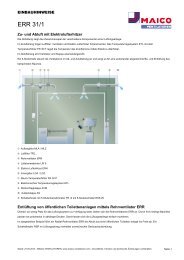
3.1 Geräteübersicht ESR.. S, DSR.. S<br />
und ESR.. EC, Abb. A<br />
1 Gehäuse<br />
2 Winkelblech<br />
3 Klemmenkasten mit Kabelverschrau-<br />
bung(en)<br />
4 Anschlussstutzen<br />
5 Bügelverschluss<br />
6 Gehäusedeckel<br />
7 Abdeckung<br />
8 Laufrad<br />
T Typenschild mit Luftrichtungspfeil<br />
3.2 Produktbeschreibung<br />
Schallgedämmte Lüftungsbox, durch doppelwandiges,<br />
schallgedämmtes Gehäuse sehr<br />
leise. Mit statisch und dynamisch gewuchtetem<br />
Radiallaufrad:<br />
● ESR.. S-Laufrad mit rückwärts gekrümmten<br />
Schaufeln mit optimalem Wirkungsgrad.<br />
● DSR.. S-Laufrad mit rückwärts gekrümmten<br />
Schaufeln mit optimalem Wirkungsgrad.<br />
● ESR.. EC-Laufrad mit rückwärts gekrümmten<br />
Schaufeln mit optimalem Wirkungsgrad.<br />
● ESR..-Laufrad mit vorwärts gekrümmten<br />
Schaufeln.<br />
Der Motor ist für Dauerbetrieb ausgelegt.<br />
● 230 V-Ausführung = ESR.. S-, ESR.. EC-<br />
und ESR..-Geräte<br />
Bei thermischer Überlastung schaltet der<br />
Motorüberlastungsschutz das Gerät aus.<br />
● 400 V-Ausführung = DSR.. S-Geräte<br />
Die Anschlüsse sind potenzialfrei auf<br />
Klemmen geführt und müssen an einen<br />
Motorvollschutzschalter Maico MV 25<br />
oder den Steuerstromkreis eines Schützes<br />
angeschlossen werden.<br />
● Ein/Aus erfolgt mit separatem Schalter<br />
(dieser ist bauseitig bereitzustellen).<br />
● ESR.. S- und ESR..-Geräte sind drehzahlsteuerbar.<br />
Für Drehzahlsteuerung siehe<br />
empfohlenes Maico-Zubehör.<br />
● ESR.. EC-Geräte sind mit einem Potentiometer<br />
mit 0…10 V-Signal drehzahlsteuerbar,<br />
zum Beispiel Maico ST-EC.<br />
3.3 Bestimmungsgemäße<br />
Verwendung<br />
● Zur Förderung kleiner bis mittlerer<br />
Luftmengen bei hohen Widerständen.<br />
● Zur Be- oder Entlüftung (je nach Einbaurichtung)<br />
von Gewerberäumen, Ausstellungsräumen,<br />
Büros, Konferenzräumen,<br />
Umkleidekabinen.<br />
● Auch als Absauganlage für Maschinen-<br />
oder Arbeitsplätze einsetzbar.<br />
● Zur Aufputzmontage in Innenräumen.<br />
● Für den direkten Einbau in Lüftungsleitungen.<br />
Einbaulage beliebig. Der Gehäusedeckel<br />
muss sich abnehmen und die<br />
Ventilatoreinheit reinigen lassen.<br />
● Anschluss saug- und druckseitig mit Nennweiten<br />
DN 125 bis DN 400, je nach Gerätevariante.<br />
● ESR.. EC: Die Drehzahleinstellung ist mit<br />
den im Maico-Sortiment gelisteten<br />
Steuergeräten/Regelgeräten zulässig,<br />
siehe Maico-Katalog oder Internet.<br />
3.4 Vorhersehbare Fehlanwendungen<br />
Maico haftet nicht für Schäden durch bestimmungswidrigen<br />
Gebrauch. Gerät auf keinen<br />
Fall einsetzen:<br />
● zur Förderung fetthaltiger Luft.<br />
● bei verstopfter Ansaugöffnung oder<br />
verstopftem Leitungsstrang.<br />
● in der Nähe von brennbaren Materialien,<br />
Flüssigkeiten oder Gasen.<br />
● zur Förderung von Chemikalien,<br />
aggressiven Gasen oder Dämpfen.<br />
● in explosionsgefährdeten Bereichen.<br />
● in Kombination mit Frequenzumrichter.<br />
D<br />
3
D<br />
4. Technische Daten<br />
Bemessungsspannung<br />
ESR.. S, ESR.. EC, ESR<br />
DSR.. S<br />
4<br />
230 V AC<br />
400 V, 3 Ph + PE<br />
Netzfrequenz 50 Hz<br />
Schutzart IP X4 bei<br />
geschlossenem<br />
Gehäusedeckel und<br />
Einbau in Lüftungsleitungen<br />
mit<br />
mindestens 1 m<br />
Rohr auf der Saug-<br />
und Druckseite<br />
Abmessungen, Gewicht<br />
Type L x B x H in mm kg<br />
ESR 12-2 S<br />
ESR 16-2 S<br />
ESR 20-2 S<br />
ESR 25-2 S<br />
ESR 31-2 S<br />
DSR 35-2 S<br />
DSR 40-2 S<br />
ESR 12 EC<br />
ESR 16 EC<br />
ESR 20 EC<br />
ESR 25 EC<br />
ESR 12-2<br />
ESR 16-2<br />
ESR 20-2<br />
ESR 25-2<br />
ESR 31-2<br />
DSR 35-2<br />
DSR 40-2<br />
384 x 383 x 232<br />
466 x 482 x 287<br />
466 x 482 x 287<br />
516 x 542 x 386<br />
516 x 542 x 386<br />
656 x 682 x 491<br />
656 x 682 x 491<br />
384 x 383 x 232<br />
466 x 482 x 287<br />
466 x 482 x 287<br />
466 x 482 x 287<br />
384 x 383 x 232<br />
384 x 383 x 232<br />
384 x 383 x 286<br />
466 x 482 x 287<br />
516 x 542 x 386<br />
656 x 682 x 491<br />
656 x 682 x 491<br />
12<br />
20<br />
20<br />
28<br />
28<br />
46<br />
46<br />
12<br />
20<br />
20<br />
20<br />
12<br />
12<br />
20<br />
18<br />
26<br />
46<br />
46<br />
5. Umgebungsbedingungen und<br />
Grenzen für den Betrieb<br />
● Zulässige Höchsttemperatur des Fördermediums:<br />
Je nach Gerätevariante<br />
45 °C ... 65 °C, siehe Typenschild.<br />
● Bei Betrieb mit raumluftabhängigen Feuerstätten<br />
muss für ausreichende Zuluftnachströmung<br />
gesorgt werden. Die maximal<br />
zulässige Druckdifferenz pro Wohneinheit<br />
beträgt 4 Pa.<br />
6. Grundlegende<br />
Sicherheitshinweise<br />
6.1 Allgemeine Sicherheitshinweise<br />
● Betriebsanleitung vor Inbetriebnahme<br />
aufmerksam durchlesen.<br />
● Anleitung aufbewahren.<br />
● Das Gerät darf nicht als Spielzeug<br />
verwendet werden.<br />
● Montage nur durch Fachkräfte zulässig.<br />
● Elektrischer Anschluss und Reparaturen<br />
nur durch Elektrofachkräfte<br />
zulässig.<br />
● Gerät nur an einer fest verlegten<br />
elektrischen Installation anschließen.<br />
– Zulässiger Leitungsquerschnitt 1,5 mm².<br />
– Vorrichtung zur Trennung vom Netz mit<br />
mindestens 3 mm Kontaktöffnung je Pol<br />
erforderlich.<br />
● Gerät nur mit auf Typenschild angegebener<br />
Spannung und Frequenz betreiben.<br />
● Gerät nur komplett montiert betreiben.<br />
● Gerät und Rohrleitung gegen Ansaugung<br />
von Fremdkörpern sichern.<br />
● Nie ohne Schutzgitter bei freier Ansaugung<br />
betreiben. Zum Beispiel Maico-Schutzgitter<br />
SG montieren.<br />
● Veränderungen und Umbauten am Gerät<br />
sind nicht zulässig und entbinden Maico<br />
von jeglicher Gewährleistung und Haftung.<br />
6.2 Sicheres und korrektes Verhalten<br />
für den Betrieb<br />
Bei Fehlverhalten besteht Verletzungsgefahr!<br />
● Keine Gegenstände in den Luftkanal oder<br />
das Gerät hineinstecken.<br />
● Drehendes Laufrad. Nicht zu nahe an das<br />
Gerät gehen, damit Haare, Kleidung oder<br />
Schmuck nicht in das Gerät hineingezogen<br />
werden können.
7. Montagevorbereitungen<br />
GEFAHR<br />
Lebensgefahr durch<br />
Stromschlag.<br />
Netzsicherung ausschalten.<br />
7.1 Wand, Decke oder Konsole<br />
i<br />
Hinweise<br />
● Einbaulage beliebig. IP X4 nur bei Einbau<br />
in Rohrleitungen mit mindestens 1 m Rohr<br />
auf der Saug- und Druckseite.<br />
● Nur an Wänden, Decken oder Konsolen mit<br />
ausreichender Tragkraft anbringen.<br />
Verletzungsgefahr durch<br />
unzureichende Befestigung<br />
der Lüftungsbox.<br />
WARNUNG Ausreichend dimensioniertes<br />
Befestigungsmaterial<br />
bereitstellen.<br />
Montageort festlegen. Ausreichend<br />
Abstand zur Wand/Decke berücksichtigen,<br />
so dass sich auch der Gehäusedeckel<br />
abnehmen und die Ventilatoreinheit<br />
herausnehmen lässt.<br />
Netzleitung zum Montageort fest verlegen.<br />
7.2 Lüftungsleitungen vorbereiten<br />
i<br />
Hinweise<br />
● Nur zum Nenndurchmesser passende<br />
Wickelfalzrohre verwenden. Zulässig sind<br />
Rohre DN 125, DN 160, DN 200, DN 250,<br />
DN 315, DN 355 oder DN 400, je nach<br />
Gerätevariante.<br />
● Bei Betrieb in staubhaltiger Umgebung<br />
Luftfilter in die Lüftungsleitung einbauen,<br />
z. B. Maico-TFE.<br />
8. Montage<br />
8.1 Lüftungsbox montieren<br />
i<br />
Lüftungsbox möglichst schwingungsentkoppelt<br />
zum Rohrsystem montieren,<br />
z. B. mit elastischer Manschette<br />
Maico-EL und Schwingungsdämpfern.<br />
Im Bereich des Montageortes für einen<br />
ebenen Untergrund sorgen.<br />
Position der 4 Befestigungsbohrungen<br />
anzeichnen und Bohrungen anbringen.<br />
Bei abgehängten Rohrsystemen Montageträger<br />
mit ausreichender Tragkraft<br />
anbringen.<br />
Lüftungsbox fest mit der Wand, Decke,<br />
Konsole oder dem Montageträger verschrauben<br />
(geeignetes Befestigungsmaterial<br />
ist bauseitig bereitzustellen).<br />
i<br />
Luftrichtungspfeil auf dem<br />
Typenschild beachten.<br />
Zulässige Wickelfalzrohre montieren und<br />
diese mit elastischen Manschetten befestigen.<br />
8.2 Elektrischer Anschluss<br />
GEFAHR<br />
i<br />
Lebensgefahr durch<br />
Stromschlag.<br />
Netzsicherung ausschalten.<br />
Warnschild gegen versehentliches<br />
Wiedereinschalten<br />
anbringen.<br />
Anschlussleitung zwischen Netz und<br />
Klemmenkasten [3] muss fest verlegt<br />
sein.<br />
Klemmenkastendeckel entfernen.<br />
VORSICHT<br />
D<br />
Kurzschlussgefahr durch<br />
Nässe bei nicht ordnungsgemäßer<br />
Einführung der<br />
Netzleitung.<br />
Netzleitung ordnungsgemäß<br />
durch Kabelverschraubung<br />
führen und anziehen.<br />
5
D<br />
Netzleitung so in den Klemmenkasten [3]<br />
einführen, dass die Kabelverschraubung<br />
die Netzleitung dicht umschließt.<br />
Bei ESR.. EC-Geräten ein zulässiges<br />
Steuergerät/Regelgerät anschließen,<br />
siehe Maico-Katalog oder Internet.<br />
Zur Drehzahleinstellung an ESR.. EC-<br />
Geräten am Potentiometer eine Mindestspannung<br />
von 0,5 V einstellen, damit der<br />
Ventilatormotor starten kann.<br />
i<br />
6<br />
Spannungen kleiner 0,5 V werden als<br />
Stoppsignal gewertet.<br />
Netzleitung an der Anschlussklemme im<br />
Klemmenkasten [3] gemäß Schaltbild<br />
anschließen, siehe Kapitel 14.<br />
Klemmenkastendeckel anbringen und mit<br />
den 4 Schrauben verschrauben.<br />
8.3 Inbetriebnahme<br />
Vor Inbetriebnahme sicherstellen, dass<br />
sich keine Gegenstände, Kleinteile,<br />
Verunreinigungen etc. in den Lüftungsleitungen<br />
befinden.<br />
Übereinstimmung mit den technischen<br />
Daten kontrollieren, siehe Typenschild.<br />
Sicherstellen, dass die Luft ungehindert<br />
strömen kann.<br />
Lüftungsbox mit separatem Ein/Aus-<br />
Schalter einschalten.<br />
Ruhigen Lauf des Ventilator-Laufrades<br />
prüfen.<br />
9. Wartung<br />
Das Gerät ist wartungsfrei.<br />
10. Reinigung<br />
ESR.. S, ESR.. EC und DSR.. S-Geräte:<br />
Der Ventilator lässt sich zum Reinigen<br />
herausschwenken.<br />
GEFAHR<br />
Lebensgefahr durch<br />
Stromschlag.<br />
Netzsicherung ausschalten<br />
und Stillstand des Laufrades<br />
abwarten.<br />
Beide Bügelverschlüsse [4] lösen und<br />
Gehäusedeckel [6] abnehmen.<br />
Beide Befestigungsschrauben der<br />
Abdeckung [7] entfernen.<br />
WARNUNG<br />
Verletzungsgefahr durch<br />
herausschwenkende<br />
Ventilatoreinheit bei Einbau<br />
im Bereich der Decke.<br />
Ventilatoreinheit nach<br />
Entfernen der Befestigungsschrauben<br />
vorsichtig und<br />
langsam ablassen.<br />
Bei Montageort in Kopfhöhe<br />
den eigenen Standort<br />
außerhalb des Schwenkbereichs<br />
wählen. Dies gilt<br />
insbesondere, wenn Sie eine<br />
Leiter benutzen.<br />
Ventilatoreinheit [8] herausschwenken.<br />
Gerät mit angefeuchtetem Tuch reinigen,<br />
gegebenenfalls aussaugen!<br />
Abdeckung [7] befestigen.<br />
Gehäusedeckel [6] anbringen und mit<br />
beiden Bügelverschlüssen [4] befestigen.
11. Störungsbehebung<br />
● Bei jeder Störung eine Elektrofachkraft<br />
hinzuziehen.<br />
● Reparaturen sind nur durch Elektrofachkräfte<br />
zulässig.<br />
GEFAHR<br />
Lebensgefahr durch<br />
Stromschlag.<br />
Netzsicherung ausschalten<br />
und Warnschild gegen<br />
unbeabsichtigtes Wiedereinschalten<br />
anbringen.<br />
Störung Maßnahme<br />
Gerätestillstand Prüfen, ob die Netzsicherung<br />
eingeschaltet ist.<br />
Thermischer<br />
Überlastungsschutz<br />
schaltet<br />
Gerät aus.<br />
Leistungs-<br />
reduzierung<br />
durch Unwucht<br />
des Laufrades.<br />
Ablagerungen<br />
am Laufrad und<br />
im Gehäuse<br />
durch staubhaltige<br />
Luft.<br />
Laufrad dreht<br />
sich nicht.<br />
Vor Wiederinbetriebnahme<br />
den Ventilator so lange<br />
ausschalten, bis Motor und<br />
Temperaturbegrenzer<br />
abgekühlt sind. Erst dann<br />
wieder einschalten.<br />
Die Abkühlzeit kann je<br />
nach Größe und Temperaturverhältnissen<br />
bis zu<br />
10 Minuten betragen.<br />
Besteht die Störung<br />
weiterhin, Elektrofachkraft<br />
hinzuziehen.<br />
Fachkraft hinzuziehen.<br />
Fachkraft hinzuziehen.<br />
Luftfilter in Rohrsystem<br />
einbauen.<br />
Innenraum auf keinen Fall<br />
mit Wasser oder Hochdruckreiniger<br />
reinigen!<br />
Gerät ausschalten.<br />
Sicherstellen, dass das<br />
Laufrad nicht durch<br />
Fremdkörper blockiert ist.<br />
12. Demontage<br />
GEFAHR<br />
i<br />
Lebensgefahr durch<br />
Stromschlag.<br />
Netzsicherung ausschalten.<br />
Die Demontage ist nur durch<br />
Elektrofachkräfte zulässig.<br />
13. Entsorgung<br />
i<br />
Nicht in den Restmüll !<br />
Das Gerät enthält teils wiederverwertbare<br />
Stoffe, teils Substanzen,<br />
die nicht in den Restmüll gelangen<br />
dürfen.<br />
Entsorgen Sie das Gerät nach Ablauf<br />
seiner Lebensdauer nach den in Ihrem<br />
Land geltenden Bestimmungen.<br />
D<br />
7
GB<br />
Sound-insulated ventilation box<br />
1. Scope of delivery<br />
Sound-insulated ventilation box including<br />
terminal box and cable screw-connections,<br />
mounting and operating instructions.<br />
2. Symbols used<br />
2.1 Warning symbols<br />
DANGER<br />
WARNING<br />
CAUTION<br />
8<br />
Danger to life.<br />
Non-observance can lead to<br />
death or serious bodily injuries.<br />
Danger of injury.<br />
Non-observance can lead to<br />
serious bodily injuries<br />
Danger of injury.<br />
Non-observance can lead to<br />
minor or more serious bodily<br />
injuries.<br />
Acknowledgements<br />
© Maico Elektroapparate-Fabrik GmbH.<br />
This instruction is a translation of the German<br />
original operating instructions. We cannot be<br />
held responsible for mistakes or printing errors<br />
and retain the right to make technical<br />
modifications without giving prior notice.<br />
2.2 Other symbols<br />
i<br />
INFO symbol:<br />
Text passages marked with this<br />
symbol contain important<br />
information and tips.<br />
● List symbol:<br />
List containing important infor-<br />
mation on the relevant subject.<br />
Action symbol:<br />
List of work to be carried out.<br />
Follow the instructions in the<br />
order given.<br />
3. Product information<br />
● ESR.. S and DSR.. S units with fan which<br />
can be swung out.<br />
● ESR.. EC units with fan which can be<br />
swung out.<br />
● ESR.. units with permanently screwed<br />
down fan.
3.1 Equipment overview ESR.. S<br />
and DSR.. S unit, Fig. A<br />
1 Housing<br />
2 Angle plate<br />
3 Terminal box with cable screwconnections<br />
4 Coupling<br />
5 Clip-locks<br />
6 Housing cover<br />
7 Cover<br />
8 Impeller<br />
T Rating plate with air direction arrow<br />
3.2 Product description<br />
Sound-insulated ventilation box. Very quiet<br />
operation, thanks to double-wall, sound<br />
insulated housing. With statically and<br />
dynamically balanced centrifugal impeller:<br />
● ESR.. S impeller with blades folded backwards<br />
for optimum efficiency.<br />
● DSR.. S impeller with blades folded backwards<br />
for optimum efficiency.<br />
● ESR.. EC impeller with blades folded backwards<br />
for optimum efficiency.<br />
● ESR.. impeller with blades folded forwards.<br />
<br />
The motor is designed for continuous<br />
operation.<br />
● 230 V model = ESR.. S, ESR.. EC and<br />
ESR.. units<br />
In the event of thermal overload, the motor<br />
overload protection switches the unit off.<br />
● 400 V model = DSR.. S units<br />
Potential-free terminal connections, which<br />
must be connected to a Maico MV 25<br />
protective motor switch or the control circuit<br />
of a contactor.<br />
● On and Off is to be carried out using a<br />
separate switch (this should be supplied<br />
by the customer).<br />
● ESR.. S and ESR.. units are speed<br />
controllable. See recommended Maico<br />
accessories for speed control.<br />
● ESR.. EC units are speed controllable<br />
through a 0...10 V signal potentiometer,<br />
e.g. Maico ST-EC.<br />
3.3 Intended use<br />
● Supply of small to medium air volumes at<br />
high resistances.<br />
● For ventilation or air extraction (depending<br />
on installation direction) of commercial<br />
premises, showrooms, offices, conference<br />
rooms, changing rooms.<br />
● Can also be used as air extraction system<br />
for machine areas or workspaces.<br />
● For surface mounting indoors.<br />
● For direct installation in ventilation ducts.<br />
Any installation position. It must be<br />
possible for the housing cover to be<br />
removed and the fan unit to be cleaned.<br />
● Connection on the inlet and outlet side with<br />
nominal sizes Ø 125 to Ø 400, depending<br />
on unit type.<br />
● ESR.. EC: Speed setting is allowed with<br />
the control units listed in the current Maico<br />
range; see Maico catalogue or the Internet.<br />
3.4 Predictable misuses<br />
Maico is not liable for damages caused by<br />
use contrary to the intended purpose.<br />
Under no circumstances should the unit<br />
be used:<br />
● for conveying greasy air.<br />
● if the intake opening or ducts are blocked.<br />
● close to flammable materials, liquids or<br />
gases.<br />
● for conveying chemicals, aggressive gases<br />
or vapours.<br />
● in areas subject to explosion hazards.<br />
GB<br />
● in combination with a frequency converter.<br />
9
GB<br />
4. Technical data<br />
Rated voltage<br />
ESR.. S, ESR.. EC,<br />
ESR DSR.. S<br />
10<br />
230 V AC<br />
400 V, 3 Ph + PE<br />
Power frequency 50 Hz<br />
Degree of protection IP X4 degree of<br />
protection with closed<br />
housing cover and<br />
when installed in ventilation<br />
ducts with at<br />
least 1 m of duct on<br />
the inlet and outlet<br />
sides<br />
Dimensions, Weight<br />
Type L x W x H in mm kg<br />
ESR 12-2 S<br />
ESR 16-2 S<br />
ESR 20-2 S<br />
ESR 25-2 S<br />
ESR 31-2 S<br />
DSR 35-2 S<br />
DSR 40-2 S<br />
ESR 12 EC<br />
ESR 16 EC<br />
ESR 20 EC<br />
ESR 25 EC<br />
ESR 12-2<br />
ESR 16-2<br />
ESR 20-2<br />
ESR 25-2<br />
ESR 31-2<br />
DSR 35-2<br />
DSR 40-2<br />
384 x 383 x 232<br />
466 x 482 x 287<br />
466 x 482 x 287<br />
516 x 542 x 386<br />
516 x 542 x 386<br />
656 x 682 x 491<br />
656 x 682 x 491<br />
384 x 383 x 232<br />
466 x 482 x 287<br />
466 x 482 x 287<br />
466 x 482 x 287<br />
384 x 383 x 232<br />
384 x 383 x 232<br />
384 x 383 x 286<br />
466 x 482 x 287<br />
516 x 542 x 386<br />
656 x 682 x 491<br />
656 x 682 x 491<br />
12<br />
20<br />
20<br />
28<br />
28<br />
46<br />
46<br />
12<br />
20<br />
20<br />
20<br />
12<br />
12<br />
20<br />
18<br />
26<br />
46<br />
46<br />
5. Environmental conditions and<br />
operating limits<br />
● Maximum permitted temperature of the<br />
air medium: Depends on unit variant<br />
45 °C...65 °C, see rating plate.<br />
● Sufficient supply air intake must be ensured<br />
during operation with air-ventilated<br />
fireplaces. The maximum permitted<br />
pressure difference per living unit is 4 Pa.<br />
6. Essential safety instructions<br />
6.1 General safety instructions<br />
● Read the operating instructions through<br />
carefully before starting up.<br />
● Keep the instructions.<br />
● The unit should not be used as a toy.<br />
● Installation is only permitted when<br />
carried out by trained specialists.<br />
● Electrical connections and repairs are<br />
only permitted when carried out by<br />
trained specialists.<br />
● Only connect the unit to a permanent<br />
electrical installation.<br />
– Permitted cable cross section: 1.5 mm²<br />
– Mains isolation device required with<br />
contact openings of at least 3 mm at each<br />
pole.<br />
● The fan unit may only be operated using<br />
the voltage and frequency shown on the<br />
rating plate.<br />
● Only operate the fan unit when it is<br />
completely installed.<br />
● Ensure that foreign bodies cannot be<br />
sucked into the unit and duct.<br />
● Never operate without protective grille with<br />
free inlet. For example, fit a Maico protective<br />
grille SG.<br />
● Modifications and alterations to the unit are<br />
not permitted and release Maico from any<br />
guarantee obligations and liability.<br />
6.2 Safe and correct practices during<br />
operation<br />
In the case of incorrect use there is the risk<br />
of injury!<br />
● Do not insert any objects in the air channel<br />
or the unit.<br />
● Rotating impeller. Do not get too close to<br />
the unit, to avoid hair, clothing or jewellery<br />
being drawn into the unit.
7. Installation preparation<br />
DANGER<br />
Danger to life from electric<br />
shock.<br />
Switch the mains fuse off.<br />
7.1 Wall, ceiling or bracket<br />
i<br />
Notes<br />
● Any installation position. IP X4 only when<br />
installed in ducts with at least 1 m of duct<br />
on the suction and pressure sides.<br />
● Only install on walls, ceilings or brackets<br />
with sufficient load-bearing capacity.<br />
WARNING<br />
Danger of injury from failure<br />
to mount ventilation box<br />
securely.<br />
Make sure you use mounting<br />
material, which is sized for the<br />
purpose.<br />
Decide on the installation location. Make<br />
sure there is sufficient distance to the<br />
wall/ceiling so that the housing cover and<br />
the fan unit can also be removed.<br />
Lay a permanent power cable to the<br />
installation location.<br />
7.2 Preparing the ventilation ducts<br />
i<br />
Notes<br />
● Only use folded spiral-seams ducts that<br />
match the nominal diameter. Ø 125,<br />
Ø 160, Ø 200, Ø 250, Ø 315, Ø 355 or<br />
Ø 400 ducts are permitted, depending on<br />
unit type.<br />
● Install an air filter in the ventilation duct,<br />
e.g. Maico TFE if operating the unit in a<br />
dusty environment.<br />
8. Installation<br />
8.1 Fitting ventilation box<br />
i<br />
As far as possible, install the<br />
ventilation box such that there is no<br />
transfer of vibrations to the duct<br />
system, e.g. by using Maico EL<br />
flexible cuffs and vibration dampers.<br />
Make sure there is a level surface at the<br />
installation location.<br />
Mark the position of the 4 mounting holes<br />
and make the holes.<br />
For suspended duct systems, fit a<br />
mounting support with sufficient loadbearing<br />
capacity.<br />
Screw the ventilation box permanently to<br />
the wall, ceiling, bracket or mounting<br />
support using suitable mounting material<br />
to be supplied by the customer.<br />
i<br />
Note air direction arrow on the<br />
rating plate.<br />
Fit permitted folded spiral-seams ducts and<br />
secure with flexible cuffs<br />
8.2 Electrical connection<br />
DANGER<br />
i<br />
Danger to life from electric<br />
shock.<br />
Switch the mains fuse off.<br />
Position a warning notice to<br />
avoid the unit being accidentally<br />
switched back on.<br />
The cabling between the power and<br />
the terminal [3] box must be<br />
permanent.<br />
Remove the terminal box cover.<br />
CAUTION<br />
GB<br />
Danger of short-circuits<br />
caused by damp if the power<br />
cable is not inserted correctly.<br />
Guide power cable correctly<br />
through cable screw-connections<br />
and tighten.<br />
11
GB<br />
Insert the power cable into the terminal box<br />
[3] such that the cable screw-connection<br />
fits tightly round the power cable.<br />
With ESR.. EC units connect a permitted<br />
control unit; see Maico catalogue or the<br />
Internet.<br />
For speed setting at the ESR.. EC units set<br />
a minimum voltage of 0.5 V at the potentiometer<br />
so that the fan motor can start.<br />
i<br />
12<br />
Voltages below 0.5 V are evaluated<br />
as a stop signal.<br />
Connect power cable to connecting<br />
terminal in terminal box [3] as shown in<br />
wiring diagram, see section 14.<br />
Fit terminal box cover and screw down with<br />
4 screws.<br />
8.3 Start-up<br />
Before start-up, ensure that there are no<br />
objects, small parts, dirt, etc., in the ven-<br />
tilation ducts.<br />
Check that the technical data has been<br />
adhered to, by reference to the rating plate.<br />
Ensure that the air can flow unhindered.<br />
Switch on ventilation box with separate<br />
on/off switch.<br />
Check that the fan impeller is running<br />
quietly.<br />
9. Maintenance<br />
The unit is maintenance-free.<br />
10. Cleaning<br />
● ESR.. S, ESR.. EC and DSR.. S units:<br />
The fan can be swung out for cleaning.<br />
<br />
DANGER<br />
Danger to life from electric<br />
shock.<br />
Switch off the mains fuse and<br />
wait for the impeller to stop.<br />
Loosen both clip-locks [4] and remove the<br />
housing cover [6].<br />
Remove both fixing screws from cover [7].<br />
WARNING<br />
Danger of injury from fan unit<br />
swinging out if fitted near<br />
ceiling.<br />
Once you have removed the<br />
fixing screws, carefully and<br />
slowly lower the fan unit.<br />
If the installation location is at<br />
head height, select a location<br />
outside the unit's swing area.<br />
This applies particularly when<br />
using a ladder.<br />
Swing the fan unit [8] out.<br />
Clean the unit with a damp cloth, suck dry<br />
if necessary.<br />
Secure cover [7].<br />
Attach the housing cover [6] and secure<br />
with the two clip-locks [4].
11. Fault rectification<br />
● Call on the services of a trained<br />
electrician any time there is a fault.<br />
● Repairs should only be carried out<br />
by a trained electrician.<br />
DANGER<br />
Danger to life from electric<br />
shock.<br />
Switch off mains fuse and<br />
hang up warning notice to<br />
prevent it from accidentally<br />
being started up again.<br />
Fault Countermeasure<br />
Unit doesn’t run Check that the mains fuse is<br />
switched on.<br />
Impeller not<br />
turning.<br />
Thermal<br />
overload<br />
protection<br />
switches the<br />
unit off.<br />
Performance<br />
reduction<br />
caused by<br />
imbalance of the<br />
impeller.<br />
Deposits on the<br />
impeller and in<br />
the housing<br />
caused by dust<br />
in the air.<br />
Switch off unit. Ensure that<br />
the impeller is not blocked<br />
by foreign bodies.<br />
Before recommissioning,<br />
switch the fan off long<br />
enough for the motor and<br />
temperature limiter to cool.<br />
Only then switch back on.<br />
Depending on size and<br />
current temperature, it may<br />
take up to 10 minutes to<br />
cool down.<br />
If the fault still continues, call<br />
on the services of a trained<br />
electrician.<br />
Call on the services of a<br />
trained specialist.<br />
Call on the services of a<br />
trained specialist.<br />
Install an air filter in the<br />
ducting.<br />
Under no circumstances<br />
should the inside of the unit<br />
be cleaned with water or a<br />
high-pressure cleaner.<br />
12. Dismantling<br />
DANGER<br />
i<br />
Danger to life from electric<br />
shock.<br />
Switch the mains fuse off.<br />
Dismantling should only be carried<br />
out by a trained electrician.<br />
13. Disposal<br />
i<br />
GB<br />
Do not dispose of in domestic<br />
waste.<br />
The unit contains in part material that<br />
can be recycled and in part<br />
substances that should not end up as<br />
domestic waste.<br />
Dispose of the unit once it has reached the<br />
end of its working life according to the<br />
regulations valid where you are.<br />
13
F<br />
Caisson d'air entrant insonorisé<br />
1. Éléments fournis<br />
Caisson d'air entrant insonorisé y compris<br />
boîte à bornes et passe-câble, notice de<br />
montage et d'utilisation.<br />
2. Symboles utilisés<br />
2.1 Symboles d'avertissement<br />
DANGER<br />
AVERTISSE-<br />
MENT<br />
PRUDENCE<br />
14<br />
Danger de mort !<br />
Le non respect peut entraîner<br />
des blessures corporelles<br />
graves, voire la mort.<br />
Risque de blessure !<br />
Le non-respect peut entraîner<br />
des blessures corporelles<br />
graves.<br />
Risque de blessure !<br />
Le non respect des symboles<br />
d'aver-tissement peut entraîner<br />
des blessures corporelles légères<br />
à moyennement graves.<br />
2.2 Autres symboles<br />
i<br />
Symbole INFO : les passages<br />
accompagnés de ce symbole<br />
fournissent des informations et<br />
conseils importants.<br />
● Symbole d'énumération :<br />
liste d’informations importantes<br />
relatives au sujet concerné.<br />
Symbole d'action :<br />
liste indiquant des actions à<br />
exécuter. Suivez les instructions<br />
dans l'ordre indiqué.<br />
3. Informations produit<br />
● Les appareils ESR.. S et DSR.. S sont<br />
équipés d'un ventilateur orientable vers<br />
l'extérieur.<br />
● Les appareils ESR.. EC sont équipés d'un<br />
ventilateur orientable vers l'extérieur.<br />
● Les appareils ESR.. sont équipés d'un<br />
ventilateur vissé.<br />
Mentions légales : © Maico Elektroapparate<br />
Fabrik GmbH. Cette instruction est une traduction<br />
de l'instruction allemande originale. Sous réserve<br />
de fautes d'impression, d'erreurs et de modifications<br />
techniques.
3.1 Vue d’ensemble de l’appareil<br />
ESR.. S, DSR.. S et ESR.. EC, Fig. A<br />
1 Boîtier<br />
2 Cornière<br />
3 Boîte à bornes avec passe-câble<br />
4 Pièces de raccordement<br />
5 Clip de fermeture<br />
6 Couvercle du boîtier<br />
7 Cache de protection<br />
8 Turbine<br />
T Plaque signalétique avec flèche de<br />
direction de l'air<br />
3.2 Description du produit<br />
Caisson d'air entrant insonorisé, très silencieux<br />
grâce au boîtier insonorisé à paroi<br />
double. Turbine radial à équilibrage statique<br />
et dynamique :<br />
● Turbine ESR.. S avec pales courbées en<br />
arrière, avec rendement optimal.<br />
● Turbine DSR.. S avec pales courbées en<br />
arrière, avec rendement optimal.<br />
● Turbine ESR.. EC avec pales courbées en<br />
arrière, avec rendement optimal.<br />
● Turbine ESR.. avec pales courbées vers<br />
l'avant.<br />
Le moteur est conçu pour un fonctionnement<br />
continu.<br />
● Modèle 230 V = Appareils ESR.. S, ESR..<br />
EC et ESR..<br />
En cas de surcharge thermique, le dispositif<br />
de sécurité contre les surcharges met le<br />
moteur hors service.<br />
● Modèle 400 V = Appareils DSR.. S<br />
Les branchements sont amenés par<br />
contacts secs sur des bornes et doivent<br />
être raccordés à un disjoncteur-protecteur<br />
moteur Maico MV 25 ou au circuit<br />
électrique de commande d'un contacteur.<br />
● Commande Marche/Arrêt par interrupteur<br />
séparé (à fournir par le client).<br />
● Il est possible de commander le régime<br />
des appareils ESR.. S et ESR... Pour la<br />
régulation du régime, voir les accessoires<br />
Maico recommandés.<br />
● La vitesse des appareils ESR.. EC, du<br />
Maico ST-EC par exemple, est commandée<br />
par un potentiomètre à signal 0…10 V.<br />
3.3 Utilisation conforme<br />
● Refoulement de débits d'air faibles à<br />
moyens en présence de résistances<br />
élevées.<br />
● Pour ventilation en entrée ou sortie (selon<br />
la direction du montage) d'ateliers, de<br />
bureaux, de salles de conférence, de<br />
cabines d'essayage.<br />
● Également utilisable comme installation<br />
d'aspiration pour les salles de machines ou<br />
les salles de travail.<br />
● Pour montage apparent dans les pièces<br />
intérieures.<br />
● Pour un montage direct dans les conduits<br />
d'air. Position de montage au choix. On<br />
doit pouvoir retirer le couvercle du boîtier<br />
pour nettoyer l'unité de ventilateur.<br />
● Raccord côté air aspiré et air comprimé<br />
d'une largeur nominale Ø 125 à Ø 400,<br />
en fonction de la variante d'appareil.<br />
● ESR.. EC : Le réglage de la vitesse de<br />
rotation est autorisé au moyen des unités<br />
de commande/régulateurs énumérés dans<br />
la gamme Maico, cf. catalogue Maico ou<br />
Internet.<br />
3.4 Erreurs d’applications prévisibles<br />
Maico décline toute responsabilité en cas de<br />
dommages résultant d'une utilisation non<br />
conforme. Ne jamais utiliser l'appareil :<br />
● pour le refoulement d'air contenant des<br />
graisses.<br />
● en cas d'ouverture d'aspiration ou de<br />
conduit bouché.<br />
● à proximité de matières, liquides ou gaz<br />
inflammables.<br />
● pour l'acheminement de produits<br />
chimiques, de gaz ou de vapeurs agressifs.<br />
● dans des zones explosibles.<br />
F<br />
● en combinaison avec un convertisseur de<br />
puissance.<br />
15
F<br />
4. Caractéristiques techniques<br />
Tension de service<br />
ESR.. S, ESR.. EC, ESR<br />
DSR.. S<br />
16<br />
230 V AC<br />
400 V, 3 Ph + PE<br />
Fréquence du secteur 50 Hz<br />
Type de protection IP X4 avec<br />
couvercle de boîtier<br />
fermé et insertion<br />
dans les conduites<br />
de ventilation avec<br />
tuyau d'au moins de<br />
1 m côté aspiration<br />
et pression<br />
Dimensions, Poids<br />
Type L x l x H à mm kg<br />
ESR 12-2 S<br />
ESR 16-2 S<br />
ESR 20-2 S<br />
ESR 25-2 S<br />
ESR 31-2 S<br />
DSR 35-2 S<br />
DSR 40-2 S<br />
ESR 12 EC<br />
ESR 16 EC<br />
ESR 20 EC<br />
ESR 25 EC<br />
ESR 12-2<br />
ESR 16-2<br />
ESR 20-2<br />
ESR 25-2<br />
ESR 31-2<br />
DSR 35-2<br />
DSR 40-2<br />
384 x 383 x 232<br />
466 x 482 x 287<br />
466 x 482 x 287<br />
516 x 542 x 386<br />
516 x 542 x 386<br />
656 x 682 x 491<br />
656 x 682 x 491<br />
384 x 383 x 232<br />
466 x 482 x 287<br />
466 x 482 x 287<br />
466 x 482 x 287<br />
384 x 383 x 232<br />
384 x 383 x 232<br />
384 x 383 x 286<br />
466 x 482 x 287<br />
516 x 542 x 386<br />
656 x 682 x 491<br />
656 x 682 x 491<br />
12<br />
20<br />
20<br />
28<br />
28<br />
46<br />
46<br />
12<br />
20<br />
20<br />
20<br />
12<br />
12<br />
20<br />
18<br />
26<br />
46<br />
46<br />
5. Conditions ambiantes et limites<br />
d'utilisation<br />
● Température maximale admissible du<br />
fluide refoulé : en fonction de la variante<br />
de l'appareil 45...65 °C, voir plaque signalétique.<br />
● Lors d'une utilisation avec des foyers<br />
dépendants de l'air ambiant, il faut veiller à<br />
une arrivée d'air suffisante. La différence<br />
de pression maximale par unité d'habitation<br />
est de 4 Pa.<br />
6. Consignes de sécurité<br />
fondamentales<br />
6.1 Consignes de sécurité générales<br />
● Lire attentivement le mode d'emploi avant<br />
la mise en service.<br />
● Conserver la notice.<br />
● L’appareil ne doit pas être utilisé comme<br />
jouet.<br />
● Montage exclusivement réservé aux<br />
professionnels.<br />
● Le branchement électrique et les réparations<br />
sont exclusivement réservés à<br />
des électriciens qualifiés.<br />
● Ne raccorder l'appareil qu'à une installation<br />
bien fixée.<br />
– Diamètre de câble autorisé : 1,5 mm².<br />
– Dispositif de coupure du réseau avec au<br />
moins une ouverture de contact nécessaire<br />
de 3 mm par pôle.<br />
● Utiliser exclusivement l'appareil à la tension<br />
et à la fréquence indiquées sur la<br />
plaque signalétique.<br />
● N’utiliser l’appareil qu’après son montage<br />
complet.<br />
● Sécuriser l'appareil et le conduit contre<br />
l'aspiration de corps étrangers.<br />
● Ne jamais faire fonctionner l'appareil sans<br />
grille de protection en cas d'aspiration libre.<br />
Monter par exemple une grille de protection<br />
Maico SG.<br />
● Les modifications et transformations<br />
apportées à l’appareil de ventilation sont<br />
rigoureusement interdites et dégagent<br />
Maico de toute responsabilité ou garantie.
6.2 Comportement sûr et correct lors<br />
du fonctionnement<br />
Risque de blessure en cas de mauvaise<br />
manipulation !<br />
● Ne pas introduire d'objet dans la gaine<br />
d'aération ou dans l'appareil.<br />
● Rotation de la turbine. Ne pas s’approcher<br />
trop près de l’appareil afin d’éviter que<br />
des cheveux, des vêtements ou des bijoux<br />
ne s’y coincent.<br />
7. Préparation au montage<br />
DANGER<br />
Risque d’électrocution.<br />
Mettre le fusible secteur hors<br />
service.<br />
7.1 Mur, plafond ou console<br />
i<br />
Remarques<br />
● Position d'installation au choix. Type de<br />
protection IP X4 uniquement lors d'un montage<br />
en conduit avec conduit d'au moins<br />
1 m du côté air aspiré et air comprimé.<br />
● Uniquement sur les murs, plafonds ou<br />
consoles présentant une force portante<br />
suffisante.<br />
AVERTIS-<br />
SEMENT<br />
Risque de blessure en cas<br />
de fixation insuffisante du<br />
caisson d'air entrant.<br />
Prévoir du matériel de fixation<br />
de dimension suffisante.<br />
Déterminer le lieu d'installation. Garantir<br />
une distance suffisante par rapport au<br />
mur/plafond, de façon à ce qu'il soit<br />
possible de retirer le couvercle du boîtier<br />
et l'unité de ventilation.<br />
Poser le câble secteur sur le lieu d'installation.<br />
7.2 Préparation des gaines d'air<br />
i<br />
Remarques<br />
● Utiliser uniquement des tuyaux agrafés<br />
adaptés au diamètre nominal. Les tuyaux<br />
Ø 125, Ø 160, Ø 200, Ø 250, Ø 315, Ø 355<br />
ou Ø 400 sont autorisés, en fonction de la<br />
variante d'appareil, sont admis.<br />
● En cas de fonctionnement dans un environnement<br />
chargé de poussières, monter<br />
un filtre à air sur la gaine d'air, comme par<br />
ex. Maico-TFE.<br />
8. Montage<br />
8.1 Montage du caisson d'air entrant<br />
i<br />
Monter le caisson d'air entrant sur le<br />
système à gaine ronde en l’isolant le<br />
plus possible contre les vibrations, via<br />
une manchette élastique Maico-EL<br />
par ex., et des plots anti-vibrations.<br />
Assurer un support plan sur le lieu d’installation.<br />
Tracer l'emplacement des 4 trous de<br />
fixation et percer les trous.<br />
En cas de systèmes à gaine ronde, utiliser<br />
un support de montage avec une force<br />
portante suffisante.<br />
Visser le caisson d'air sortant sur le mur, le<br />
plafond, la console ou le support de<br />
montage (préparer le matériau de fixation<br />
côté œuvre de manière adéquate).<br />
i<br />
Respecter la flèche du sens de<br />
l'air se trouvant sur la plaque<br />
signalétique.<br />
Monter la gaine agrafée autorisée et la<br />
fixer avec des manchettes flexibles.<br />
F<br />
17
8.2 Branchement électrique<br />
DANGER<br />
i<br />
F<br />
18<br />
Risque d’électrocution.<br />
Mettre le fusible secteur hors<br />
service.<br />
Apposer un panneau d'avertissement<br />
prévenant toute remise<br />
en service intempestive.<br />
Le conduit de raccordement qui<br />
sépare le secteur de la boîte à bornes<br />
[3] doit être bien fixé.<br />
Retirer le couvercle de la boîte à bornes.<br />
PRUDENCE<br />
Risque de court-circuit en cas<br />
d’humidité liée à une insertion<br />
incorrecte du câble-secteur.<br />
Mettre en place et tirer les<br />
câbles secteur au travers de<br />
passe-câble à vis.<br />
Insérer le câble secteur dans la boîte à<br />
bornes [3] de façon à ce que le passecâble<br />
à vis enserre fermement le câble<br />
secteur.<br />
Avec les appareils ESR.. EC, connecter<br />
une unité de commande/un régulateur<br />
autorisé, cf. catalogue Maico ou Internet.<br />
Pour régler la vitesse de rotation des appareils<br />
ESR.. EC, sélectionner une tension<br />
minimum de 0,5 V au potentiomètre<br />
permettant le démarrage du moteur de<br />
ventilateur.<br />
i<br />
Les tensions inférieures à 0,5 V sont<br />
assimilées à un signal d'arrêt.<br />
Raccorder le câbles secteur à la fiche de<br />
la boîte à bornes [3] selon le schéma<br />
électrique, voir chapitre 14.<br />
Mettre le couvercle de la boîte à bornes en<br />
place et le visser à l'aide des 4 vis.<br />
8.3 Mise en service<br />
Avant la mise en service, s’assurer que les<br />
gaines d'air sont exemptes d’objets, de<br />
petites pièces ou d’impuretés.<br />
Contrôler la concordance avec les<br />
caractéristiques techniques, cf. plaque<br />
signalétique.<br />
S’assurer que l’air peut circuler librement.<br />
Allumer le caisson d'air entrant avec<br />
l’interrupteur Marche/Arrêt séparé.<br />
Vérifier le fonctionnement régulier de la<br />
turbine du ventilateur.<br />
9. Maintenance<br />
L'appareil ne nécessite aucune maintenance.<br />
10. Nettoyage<br />
Appareils ESR.. S, ESR.. EC et DSR.. S:<br />
Pour le nettoyage, sortir le ventilateur en<br />
le basculant.<br />
DANGER<br />
Risque d’électrocution.<br />
Mettre le fusible secteur hors<br />
service et attendre jusqu'à ce<br />
que la turbine soit à l'arrêt .<br />
Desserrer les deux clips de fermeture [4] et<br />
retirer le couvercle du boîtier [6].<br />
Retirer les vis de fixation du couvercle [7].<br />
AVERTIS-<br />
SEMENT<br />
Risque de danger par le<br />
basculement vers l'extérieur<br />
de l'unité de ventilation,<br />
au niveau du couvercle, à<br />
proximité du site d'intégration.<br />
Extraire l'unité de ventilation<br />
lentement et avec précaution<br />
après avoir retiré les vis de<br />
fixation.<br />
Si le montage a lieu sur un<br />
site situé à hauteur d'homme,<br />
prendre en compte la zone de<br />
basculement lors du choix du<br />
site. Ceci est particulièrement<br />
important si vous utilisez une<br />
échelle.<br />
Faire basculer l'unité de ventilation en la<br />
basculant.<br />
Nettoyer l'appareil avec un chiffon humidifié,<br />
aspirer éventuellement.<br />
Fixez le revêtement [7].<br />
Mettre en place le couvercle du boîtier [6]<br />
et le fixer à l'aide des deux clips de fermeture<br />
[4].
11. Élimination des défauts<br />
● Lors de tout dysfonctionnement, consulter<br />
un électricien.<br />
● Les réparations sont exclusivement<br />
réservées à des électriciens qualifiés.<br />
DANGER<br />
Dysfonctionnement<br />
Risque d’électrocution.<br />
Mettre le fusible secteur hors<br />
service et mettre en place un<br />
panneau d'avertissement pour<br />
éviter une remise en marche<br />
inopinée.<br />
Mesure<br />
Arrêt de l'appareil Vérifier que le fusible<br />
secteur est enclenché.<br />
La protection<br />
thermique contre<br />
les surcharges<br />
met l'appareil à<br />
l'arrêt.<br />
Baisse du rendement<br />
lié à un<br />
balourd de la<br />
turbine.<br />
Dépôts sur la<br />
turbine et dans le<br />
châssis dus à l’air<br />
chargé de<br />
poussières.<br />
La turbine ne<br />
tourne pas.<br />
Avant toute remise en<br />
service, maintenir le<br />
ventilateur à l'arrêt jusqu'à<br />
ce que le moteur et le<br />
limiteur de température<br />
soient refroidis. Ne<br />
procéder alors qu'à la<br />
remise en service.<br />
Le temps de refroidissement<br />
peut atteindre<br />
10 minutes en fonction de<br />
la taille et des températures<br />
ambiantes.<br />
Si le dysfonctionnement<br />
persiste, faire appel à un<br />
électrotechnicien.<br />
Contacter un spécialiste.<br />
Contacter un spécialiste.<br />
Monter le filtre à air dans<br />
le système à gaine ronde.<br />
Ne nettoyer en aucun cas<br />
l'intérieur avec de l'eau ou<br />
un nettoyeur à pression !<br />
Mettre l'appareil à l’arrêt.<br />
S’assurer que la turbine<br />
n’est pas bloquée par des<br />
corps étrangers.<br />
12. Démontage<br />
DANGER<br />
i<br />
Risque d’électrocution.<br />
Mettre le fusible secteur hors<br />
service.<br />
Le démontage est exclusivement<br />
réservé à des électriciens qualifiés.<br />
13. Élimination<br />
i<br />
Ne pas mettre au rebut avec les<br />
déchets ménagers.<br />
L'appareil contient des matériaux<br />
partiellement recyclables,<br />
ne devant pas être mises au rebut<br />
avec les déchets ménagers.<br />
Éliminez l'appareil arrivé en fin de vie en<br />
respectant les dispositions applicables<br />
dans votre pays.<br />
F<br />
19
D GB<br />
F<br />
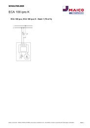
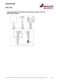
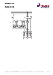
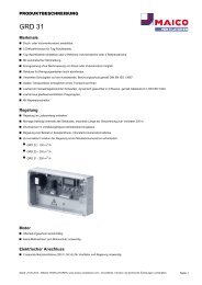
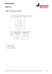
14. Schaltbilder / Wiring diagrams / Schémas de branchement<br />
ESR.. S<br />
DSR.. S<br />
20<br />
TW = Steuerstromkreis / Control circuit / Circuit de commande
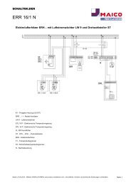
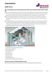
ESR.. EC<br />
F GB<br />
D<br />
21
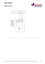
ESR..<br />
D GB<br />
F<br />
22<br />
TW = Steuerstromkreis / Control circuit / Circuit de commande
24<br />
Maico Elektroapparate-Fabrik GmbH • Steinbeisstr. 20 • 78056 Villingen-Schwenningen •<br />
Germany • Service +49 7720 694 447 • technik@maico.de RLF.3_11.12_DSW_ru 11.12