Bedienungsanleitung LaNordica INSERTO Crystal-50-70-80-100
Bedienungsanleitung LaNordica INSERTO Crystal-50-70-80-100
Bedienungsanleitung LaNordica INSERTO Crystal-50-70-80-100

You also want an ePaper? Increase the reach of your titles
YUMPU automatically turns print PDFs into web optimized ePapers that Google loves.
ISTRUZIONI PER L’INSTALLAZIONE, L’USO E LA MANUTENZIONE - IT<br />
INSTRUCTIONS FOR INSTALLATION, USE AND MAINTENANCE - EN<br />
ANWEISUNGEN FÜR DIE AUFSTELLUNG, DEN GEBRAUCH UND DIE WARTUNG – DE<br />
INSTRUCTIONS POUR L’INSTALLATION, L’UTILISATION ET L’ENTRETIEN – FR<br />
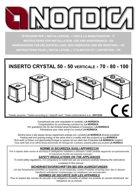
<strong>INSERTO</strong> CRYSTAL <strong>50</strong> - <strong>50</strong> VERTICALE - <strong>70</strong> - <strong>80</strong> - <strong>100</strong><br />
|<br />
Testato secondo / Tested according to / Geprüft nach / Testé conformément à la : EN13229<br />
Complimenti per aver acquistato un prodotto: LA NORDICA.<br />
Congratulations for purchasing a product by: La NORDICA.<br />
Wir gratulieren Sie für den Einkauf eines Einsatzes in Gusseisen: LA NORDICA.<br />
Félicitations pour votre achat d’un produit LA NORDICA<br />
•<br />
Sentirsi bene e allo stesso tempo risparmiare energia con i prodotti LA NORDICA diventa possibile!<br />
Feeling well and sparing energy at the same time is a reality with the products by La NORDICA<br />
Sich wohl zu fühlen und gleichzeitig Energie zu sparen ist nun dank den Produkten LA NORDICA möglich!<br />
Vous sentir bien et en même temps économiser de l’énergie est, à présent, possible grâce aux produits LA NORDICA<br />
NORME DI SICUREZZA SUGLI APPARECCHI<br />
Per il rispetto delle norme di sicurezza è obbligatorio installare e utilizzare i nostri prodotti seguendo scrupolosamente<br />
le indicazioni fornite nel presente manuale.<br />
SAFETY REGULATIONS ON THE APPLIANCES<br />
To meet safety regulations, it is compulsory to install and use our products carefully following the instructions<br />
contained in this manual.<br />
SICHERHEITSVORSCHRIFTEN BEI DEN AUSRÜSTUNGEN<br />
Um die Sicherheitsvorschriften zu beachten, ist es notwendig, unsere Produkte vorsichtig nach den in diesem<br />
Handbuch enthaltenen Anweisungen zu installieren und anzuwenden.<br />
NORMES DE SECURITE SUR LES APPAREILS<br />
Pour le respect des normes de sécurité, il est obligatoire d'installer et utiliser nos produits en suivant strictement les<br />
indications de ce manuel.
<strong>INSERTO</strong> <strong>50</strong> – <strong>50</strong> VERTICALE – <strong>70</strong> – <strong>80</strong> – <strong>100</strong><br />
2 6096<strong>80</strong>1 - Rev.09 – IT – EN – DE – FR
<strong>INSERTO</strong> <strong>Crystal</strong> <strong>50</strong> – <strong>50</strong> VERTICALE – <strong>70</strong> – <strong>80</strong> – <strong>100</strong><br />
DICHIARAZIONE DI CONFORMITA’ DEL COSTRUTTORE<br />
Oggetto: assenza di amianto e cadmio<br />
Si dichiara che tutti i nostri apparecchi vengono assemblati con materiali che non presentano parti di<br />
amianto o suoi derivati e che nel materiale d’apporto utilizzato per le saldature non è presente/utilizzato in<br />
nessuna forma il cadmio, come previsto dalla norma di riferimento.<br />
Oggetto: Regolamento CE n. 1935/2004<br />
Si dichiara che in tutti gli apparecchi da noi prodotti, i materiali destinati a venire a contatto con i cibi sono<br />
adatti all’uso alimentari, in conformità al Regolamento CE in oggetto.<br />
DECLARATION OF CONFORMITY OF THE MANUFACTURER<br />
Object: Absence of asbestos and cadmium<br />
We declare that the materials used for the assembly of all our appliances are without asbestos parts or<br />
asbestos derivates and that in the material used for welding, cadmium is not present, as prescribed in<br />
relevant norm.<br />
Object: CE n. 1935/2004 regulation.<br />
We declare that in all products we produce, the materials which will get in touch with food are suitable for<br />
alimentary use, according to the a.m. CE regulation.<br />
KONFORMITÄTSERKLÄRUNG DES HERSTELLERS<br />
Betreff: Fehlen von Asbest und Kadmium<br />
Wir bestätigen, dass die verwendeten Materialen oder Teilen für die Herstellung der La Nordica Geräte<br />
ohne Asbest und Derivat sind und auch das Lot für das Schweißen immer ohne Kadmium ist.<br />
Betreff: Ordnung CE n. 1935/2004.Wir erklären in alleiniger Verantwortung, dass die Materialen der Teile,<br />
die für den Kontakt mit Lebensmitteln vorgesehen sind, für die Nahrungsbenutzung geeignet sind und der<br />
Richtlinien CE n. 1935/2004 erfüllen.<br />
DECLARATION DE CONFORMITE DU FABRICANT<br />
Objet: absence d’amiante et de cadmium<br />
Nous déclarons que tous nos appareils sont fabriqués avec des matériaux qui ne présentent pas de pièces<br />
en amiante ou ses dérivés et que le matériel d’apport utilisé pour les soudures ne contient/n’utilise sous<br />
aucune forme du cadmium, comme prévu dans la norme de référence.<br />
Objet: Règlement CE n. 1935/2004<br />
Nous déclarons que sur tous nos appareils, les matériaux destinés à entrer en contact avec les aliments<br />
sont adéquats à l’usage alimentaire, conformément au Règlement CE en objet.<br />
6096<strong>80</strong>1 - Rev.09 – IT – EN – DE – FR 3
<strong>INSERTO</strong> <strong>50</strong> – <strong>50</strong> VERTICALE – <strong>70</strong> – <strong>80</strong> – <strong>100</strong><br />
INDICE IT<br />
1. AVVERTENZE GENERALI ................................................................................................................................................. 6<br />
2. DESCRIZIONE................................................................................................................................................................... 6<br />
3. NORME PER L’INSTALLAZIONE ....................................................................................................................................... 6<br />
4. SICUREZZA ANTINCENDIO .............................................................................................................................................. 7<br />
4.1. PRONTO INTERVENTO ............................................................................................................................................ 7<br />
4.2. PROTEZIONI DELLE TRAVI ...................................................................................................................................... 7<br />
5. CANNA FUMARIA.............................................................................................................................................................. 8<br />
5.1. COMIGNOLO............................................................................................................................................................. 9<br />
6. VENTILAZIONE CAPPA O LOCALE ADIACENTE............................................................................................................. 10<br />
7. COLLEGAMENTO ALLA CANNA FUMARIA / ARIA PER LA COMBUSTIONE (presa d’aria) .............................................. 11<br />
8. PRESA D’ARIA ESTERNA ............................................................................................................................................... 12<br />
9. COLLEGAMENTO E MANUTENZIONE VENTILAZIONE................................................................................................... 13<br />
10. COMBUSTIBILI AMMESSI / NON AMMESSI ................................................................................................................ 14<br />
11. ACCENSIONE ............................................................................................................................................................. 14<br />
12. FUNZIONAMENTO NORMALE .................................................................................................................................... 15<br />
13. FUNZIONAMENTO NEI PERIODI DI TRANSIZIONE .................................................................................................... 16<br />
14. MANUTENZIONE E CURA........................................................................................................................................... 16<br />
14.1. PULIZIA DELLA CANNA FUMARIA.......................................................................................................................... 16<br />
14.2. PULIZIA DEL VETRO............................................................................................................................................... 16<br />
14.3. PULIZIA DALLA CENERE ........................................................................................................................................ 16<br />
15. FERMO ESTIVO .......................................................................................................................................................... 17<br />
16. DETERMINAZIONE DELLA POTENZA TERMICA ........................................................................................................ 17<br />
17. SCHEDE TECNICHE / TECHNICAL DATA SHEETS / TECHNISCHE PROTOKOLLE / FICHE TECHNIQUE.................. 55<br />
18. CARATTERISTICHE TECNICHE / TECHNICAL FEATURES / TECHNISCHE MERKMALE / CARACTERISTIQUES<br />
TECHNIQUES .......................................................................................................................................................................... 57<br />
19. VENTILAZIONE in dotazione / Seires VENTILATION / LÜFTUNG – Schon dabei / VENTILATION DU SERIE /<br />
VENTILATION DU SERIE ......................................................................................................................................................... 59<br />
20. Collegamento elettrico kit ventilazione OPZIONALE / Electric connection for the OPTIONAL ventilation kit / Elektrische<br />
verbindung des EXTRA kit gebläse / Connexion électrique du kit ventilation OPTIONNEL........................................................... 60<br />
INDEX EN<br />
1. GENERAL REMARKS...................................................................................................................................................... 18<br />
2. DESCRIPTION................................................................................................................................................................. 18<br />
3. REGULATIONS FOR INSTALLATION .............................................................................................................................. 18<br />
4. FIRE-FIGHTING SAFETY MEASURES............................................................................................................................. 19<br />
4.1. FIRST-AID MEASURES ........................................................................................................................................... 19<br />
4.2. BEAM PROTECTIONS............................................................................................................................................. 19<br />
5. FLUE ............................................................................................................................................................................... 20<br />
5.1. CHIMNEY CAP ........................................................................................................................................................ 21<br />
6. VENTILATION HOOD OR ADJACENT LOCAL.................................................................................................................. 22<br />
7. CONNECTION TO THE FLUE / AIR FOR COMBUSTION (air intake) ................................................................................ 23<br />
8. EXTERNAL AIR INTAKE .................................................................................................................................................. 24<br />
9. CONNECTION AND MAINTENANCE OF VENTILATION .................................................................................................. 25<br />
10. ALLOWED / NOT ALLOWED FUELS............................................................................................................................ 26<br />
11. LIGHTING.................................................................................................................................................................... 26<br />
12. NORMAL OPERATION ................................................................................................................................................ 27<br />
13. OPERATION DURING TRANSITION PERIODS............................................................................................................ 28<br />
14. MAINTENANCE AND CARE......................................................................................................................................... 28<br />
14.1. CLEANING OF THE FLUE ....................................................................................................................................... 28<br />
14.2. CLEANING OF THE GLASS..................................................................................................................................... 28<br />
14.3. CLEANING OF THE ASH......................................................................................................................................... 28<br />
15. SUMMER TIME............................................................................................................................................................ 29<br />
16. CALCULATION OF THE THERMAL POWER................................................................................................................ 29<br />
17. SCHEDE TECNICHE / TECHNICAL DATA SHEETS / TECHNISCHE PROTOKOLLE / FICHE TECHNIQUE.................. 55<br />
18. CARATTERISTICHE TECNICHE / TECHNICAL FEATURES / TECHNISCHE MERKMALE / CARACTERISTIQUES<br />
TECHNIQUES .......................................................................................................................................................................... 57<br />
19. VENTILAZIONE in dotazione / Seires VENTILATION / LÜFTUNG – Schon dabei / VENTILATION DU SERIE /<br />
VENTILATION DU SERIE ......................................................................................................................................................... 59<br />
20. Collegamento elettrico kit ventilazione OPZIONALE / Electric connection for the OPTIONAL ventilation kit / Elektrische<br />
verbindung des EXTRA kit gebläse / Connexion électrique du kit ventilation OPTIONNEL........................................................... 60<br />
4 6096<strong>80</strong>1 - Rev.09 – IT – EN – DE – FR
<strong>INSERTO</strong> <strong>Crystal</strong> <strong>50</strong> – <strong>50</strong> VERTICALE – <strong>70</strong> – <strong>80</strong> – <strong>100</strong><br />
INHALTVERZEICHNIS DE<br />
1. ALLGEMEINE ANWEISUNGEN........................................................................................................................................ 30<br />
2. BESCHREIBUNG............................................................................................................................................................. 30<br />
3. AUFSTELLUNGSVORSCHRIFTEN .................................................................................................................................. 30<br />
4. BRANDSCHUTZ .............................................................................................................................................................. 31<br />
4.1. NOTHILFEINTERVENTION...................................................................................................................................... 31<br />
4.2. TRÄGERSCHUTZ.................................................................................................................................................... 32<br />
5. SCHORNSTEINROHR ..................................................................................................................................................... 32<br />
5.1. SCHORNSTEIN....................................................................................................................................................... 33<br />
6. LÜFTUNG DURCH HAUBE ODER NAHELIEGENDEN RAUM .......................................................................................... 35<br />
7. VERBINDUNG ZUM SCHORNSTEINROHR / LUFT FÜR DIE VERBRENNUNG (LUFTEINLASS)...................................... 36<br />
8. AUßENLUFTEINLASS...................................................................................................................................................... 36<br />
9. LÜFTUNGSVERBINDUNG UND -WARTUNG ................................................................................................................... 38<br />
10. ZULÄSSIGE / UNZULÄSSIGE BRENNSTOFFE............................................................................................................ 39<br />
11. ANFEUERUNG ............................................................................................................................................................ 39<br />
12. NORMALER BETRIEB ................................................................................................................................................. 40<br />
13. BETRIEB IN DEN ÜBERGANGSPERIODEN ................................................................................................................ 41<br />
14. WARTUNG UND PFLEGE............................................................................................................................................ 41<br />
14.1. REINIGUNG DES SCHORNSTEINROHRES ............................................................................................................ 41<br />
14.2. REINIGUNG DES GLASES...................................................................................................................................... 41<br />
14.3. ENTFERNUNG DER ASCHE ................................................................................................................................... 41<br />
15. SOMMERLICHE STILLLEGUNG .................................................................................................................................. 42<br />
16. FESTSTELLUNG DER WÄRMELEISTUNG .................................................................................................................. 42<br />
17. SCHEDE TECNICHE / TECHNICAL DATA SHEETS / TECHNISCHE PROTOKOLLE / FICHE TECHNIQUE.................. 55<br />
18. CARATTERISTICHE TECNICHE / TECHNICAL FEATURES / TECHNISCHE MERKMALE / CARACTERISTIQUES<br />
TECHNIQUES .......................................................................................................................................................................... 57<br />
19. VENTILAZIONE in dotazione / Seires VENTILATION / LÜFTUNG – Schon dabei / VENTILATION DU SERIE /<br />
VENTILATION DU SERIE ......................................................................................................................................................... 59<br />
20. Collegamento elettrico kit ventilazione OPZIONALE / Electric connection for the OPTIONAL ventilation kit / Elektrische<br />
verbindung des EXTRA kit gebläse / Connexion électrique du kit ventilation OPTIONNEL........................................................... 60<br />
SOMMAIRE FR<br />
1. AVERTISSEMENT GENERAL .......................................................................................................................................... 43<br />
2. DESCRIPTION................................................................................................................................................................. 43<br />
3. NORMES POUR L’INSTALLATION................................................................................................................................... 43<br />
4. SECURITE ANTI-INCENDIE............................................................................................................................................. 44<br />
4.1. INTERVENTION RAPIDE......................................................................................................................................... 44<br />
4.2. PROTECTION DES POUTRES ................................................................................................................................ 44<br />
5. TUYAU D'EVACUATION .................................................................................................................................................. 45<br />
5.1. TÉTÉ DE CHEMINEE............................................................................................................................................... 46<br />
6. VENTILATION HOTTE OU LOCAL ADJACENT ................................................................................................................ 47<br />
7. CONNEXION au TUYAU D'ÉVACUATION / AIR POUR LA COMBUSTION (prise d’air)...................................................... 48<br />
8. PRISE D’AIR EXTERNE................................................................................................................................................... 49<br />
9. CONNEXION ET ENTRETIEN.......................................................................................................................................... <strong>50</strong><br />
10. COMBUSTIBLES ADMIS / NON ADMIS ....................................................................................................................... 51<br />
11. ALLUMAGE ................................................................................................................................................................. 51<br />
12. FONCTIONNEMENT NORMAL .................................................................................................................................... 52<br />
13. FONCTIONNEMENT PENDANT LES PERIODES DE TRANSITION ............................................................................. 53<br />
14. ENTRETIEN ET SOIN.................................................................................................................................................. 53<br />
14.1. NETTOYAGE DU TUYAU D’EVACUATION DE LA FUMEE....................................................................................... 53<br />
14.2. NETTOYAGE DE LA VITRE..................................................................................................................................... 53<br />
14.3. NETTOYAGE TIROIR DES CENDRES..................................................................................................................... 53<br />
15. ARRET PENDANT L’ETE............................................................................................................................................. 54<br />
16. DETERMINATION DE LA PUISSANCE THERMIQUE................................................................................................... 54<br />
17. SCHEDE TECNICHE / TECHNICAL DATA SHEETS / TECHNISCHE PROTOKOLLE / FICHE TECHNIQUE.................. 55<br />
18. CARATTERISTICHE TECNICHE / TECHNICAL FEATURES / TECHNISCHE MERKMALE / CARACTERISTIQUES<br />
TECHNIQUES .......................................................................................................................................................................... 57<br />
19. VENTILAZIONE in dotazione / Seires VENTILATION / LÜFTUNG – Schon dabei / VENTILATION DU SERIE /<br />
VENTILATION DU SERIE ......................................................................................................................................................... 59<br />
20. Collegamento elettrico kit ventilazione OPZIONALE / Electric connection for the OPTIONAL ventilation kit / Elektrische<br />
verbindung des EXTRA kit gebläse / Connexion électrique du kit ventilation OPTIONNEL........................................................... 60<br />
6096<strong>80</strong>1 - Rev.09 – IT – EN – DE – FR 5
1. AVVERTENZE GENERALI<br />
<strong>INSERTO</strong> <strong>50</strong> – <strong>50</strong> VERTICALE – <strong>70</strong> – <strong>80</strong> – <strong>100</strong><br />
L’installazione di un camino deve avvenire in conformità alle leggi e ai regolamenti di ciascun paese.<br />
La nostra responsabilità è limitata alla fornitura dell’apparecchio. Il suo impianto va realizzato in modo<br />
conforme alla regola dell’arte, secondo le prescrizioni delle presenti istruzioni e le regole della professione,<br />
da personale qualificato, che agisce a nome di imprese adatte ad assumere l'intera responsabilità<br />
dell'insieme dell'impianto.<br />
La Nordica s.p.a. non è responsabile del prodotto modificato senza autorizzazione e tanto meno per l’uso di ricambi<br />
non originali.<br />
Questo apparecchio non è adatto all’uso da parte di persone (inclusi bambini) con capacità fisiche, sensoriali e<br />
mentali ridotte, o inesperte, a meno che non vengano supervisionate ed istruite nell’uso dell’apparecchio da una<br />
persona responsabile per la loro sicurezza. I bambini devono essere controllati per assicurarsi che non giochino con<br />
l’apparecchio (EN60335-2-102 / 7.12).<br />
2. DESCRIZIONE<br />
L’apparecchio è composto da una camera in acciaio interamente saldata a tenuta ermetica. Il focolare è internamente<br />
rivestito da singole lastre in ghisa e refrattario (ironker).<br />
Al suo interno si trovano un portagriglia ed una griglia piana, in ghisa di grosso spessore, facilmente estraibili.<br />
Gli apparecchi possiedono un circuito d’aria integrato per il recupero del calore composto da un carter, esterno al<br />
corpo di riscaldamento, in acciaio zincato.<br />
L’inserto è dotato di una porta panoramica con vetro ceramico (resistente fino a <strong>70</strong>0°C), questo consen te<br />
un’affascinante vista sulle fiamme ardenti ed inoltre viene così impedita ogni possibile fuoriuscita di scintille e fumo.<br />
Sotto la griglia del focolare si trova un cassetto cenere facilmente estraibile anche ad apparecchio in funzione.<br />
Il riscaldamento dell’ambiente avviene:<br />
a) per convezione: il passaggio dell’aria attraverso il mantello e la cappa di rivestimento del focolare rilascia<br />
calore nell’ambiente.<br />
b) per radiazione: attraverso il vetro panoramico e il corpo in refrattario (ironker) viene irraggiato calore<br />
nell’ambiente.<br />
L’apparecchio è dotato di registri per l’aria primaria e secondaria, con i quali viene regolata l’aria di combustione.<br />
1A - Fig. 1 Registro aria primaria<br />
Con il registro dell’aria posto (a sinistra) sotto la porta del focolare<br />
viene regolato il passaggio dell’aria attraverso il cassetto cenere e<br />
la griglia in direzione del combustibile. L’aria primaria è necessaria<br />
per il processo di combustione in fase di accensione .<br />
Per aprire il passaggio dell’aria primaria bisogna estrarre (tirare)<br />
totalmente la leva .<br />
Il cassetto cenere deve essere svuotato regolarmente, in modo<br />
che la cenere non possa ostacolare l’entrata dell’aria primaria per<br />
la combustione (Fig. 20-A). Attraverso l’aria primaria viene anche<br />
mantenuto vivo il fuoco.<br />
Durante la combustione di legna, il registro dell’aria primaria<br />
deve essere aperto solo un poco, poiché altrimenti la legna<br />
arde velocemente e l’apparecchio si può surriscaldare.<br />
2A - Fig. 1 Registro aria secondaria<br />
Sotto la porta del focolare (a destra) si trova un registro dell’aria secondaria.<br />
Questa valvola deve essere aperta (quindi tutta inserita) in particolare per la combustione di legna, cosicché il<br />
carbonio incombusto può subire una post-combustione, aumentando il rendimento e garantendo la pulizia del vetro<br />
(v. CAP. 12 ).<br />
3. NORME PER L’INSTALLAZIONE<br />
Fig. 1<br />
E’ obbligatorio rispettare norme nazionali ed europee, disposizioni locali o in materia edilizia, nonché<br />
regolamentazioni antincendio.<br />
Il Vostro abituale spazzacamino di zona deve essere informato sull’installazione dell’apparecchio, affinché possa<br />
verificare il regolare collegamento dello stesso al camino.<br />
Prima dell’installazione eseguire le seguenti verifiche :<br />
• accertarsi che il pavimento possa sopportare il peso dell’apparecchio e provvedere ad un adeguato isolamento<br />
nel caso sia costruito in materiale infiammabile;<br />
• assicurarsi che nella stanza dove sarà installato vi sia una ventilazione adeguata (presenza di presa d’aria);<br />
• evitare l’installazione in locali con presenza di condotti di ventilazione collettivo, cappe con o senza estrattore,<br />
apparecchi a gas di tipo B, pompe di calore o la presenza di apparecchi il cui funzionamento contemporaneo<br />
possa mettere in depressione il locale (rif. Norma UNI 10683/98);<br />
6 6096<strong>80</strong>1 - Rev.09 – IT<br />
1A<br />
2A
<strong>INSERTO</strong> <strong>Crystal</strong> <strong>50</strong> – <strong>50</strong> VERTICALE – <strong>70</strong> – <strong>80</strong> – <strong>100</strong><br />
• accertarsi che la canna fumaria e i tubi a cui verrà collegato l’apparecchio siano idonei al funzionamento dello<br />
stesso.<br />
• lasciare sempre un minimo di vuoto d’aria tra l’<strong>INSERTO</strong> e le pareti, laterale e posteriore, come indicato in Fig.<br />
14 e Fig. 15<br />
Vi consigliamo di far verificare dal Vostro abituale spazzacamino di zona sia il collegamento al camino sia il sufficiente<br />
afflusso d’aria per la combustione nel luogo d’installazione.<br />
4. SICUREZZA ANTINCENDIO<br />
Nell’installazione dell’apparecchio devono essere osservate le seguenti misure di sicurezza (Fig. 2):<br />
a) davanti al focolare non deve esserci alcun oggetto o materiale di costruzione infiammabile e sensibile al calore a<br />
meno di <strong>80</strong> cm di distanza. Tale distanza può essere ridotta a 40 cm qualora venga installata una protezione,<br />
retroventilata e resistente al calore, davanti all’intero componente da proteggere;<br />
b) qualora l’apparecchio venga installato su un pavimento non completamente refrattario, bisogna prevedere un<br />
sottofondo ignifugo, per esempio una pedana d'acciaio (dimensioni secondo l’ordinamento regionale).<br />
L’inserto deve funzionare esclusivamente con il cassetto cenere inserito.<br />
I residui solidi della combustione (ceneri) devono essere raccolti in un contenitore ermetico e resistente al fuoco.<br />
L’apparecchio non deve mai essere acceso in presenza di emissioni gassose o vapori (per esempio colla per<br />
linoleum, benzina ecc.). Non depositate materiali infiammabili nelle vicinanze dello stesso.<br />
Avvertire i bambini che l’inserto diventa molto caldo e che non deve essere toccato.<br />
Fig. 2<br />
Protezione del pavimento con<br />
materiale incombustibile<br />
Pavimentazione in<br />
materiale combustibile<br />
4.1. PRONTO INTERVENTO<br />
Se si manifesta un incendio nel camino o nella canna fumaria:<br />
a) Chiudere la porta di caricamento.<br />
b) Chiudere i registri dell’aria comburente<br />
c) Spegnere tramite l’uso di estintori ad anidride carbonica (CO2 a polveri )<br />
d) Richiedere l’immediato intervento dei VIGILI del FUOCO<br />
NON SPEGNERE IL FUOCO CON L’USO DI GETTI D’ACQUA.<br />
Quando la canna fumaria smette di bruciare, bisogna farla verificare da uno specialista per individuare eventuali<br />
crepe o punti permeabili.<br />
4.2. PROTEZIONI DELLE TRAVI<br />
Tenendo conto dell’irradiazione del focolare, dovete essere particolarmente attenti alla protezione delle travi nella<br />
progettazione del vostro camino, tenete conto da una<br />
parte della prossimità della trave dalle facce esterne<br />
(3) 10 mm (1)<br />
(3) 10 mm (1)<br />
(3) 10 mm<br />
(1)<br />
del focolare, e dall’altra dell’irradiazione della porta in<br />
vetro che normalmente è molto vicina alle travi stesse.<br />
(2)<br />
(4)<br />
(2)<br />
(2)<br />
Sappiate che in qualsiasi caso, le facce interne o<br />
inferiori di questa trave in materiale combustibile non<br />
devono essere in contatto con temperature superiori ai<br />
(3) 10 mm<br />
(1) (3) 10÷<strong>50</strong> mm (1)<br />
(3) 10 mm (1)<br />
65 °C.<br />
(2)<br />
(2)<br />
In Fig. 3 sono riportati alcuni esempi di soluzione.<br />
(2)<br />
(4)<br />
AVVERTENZA: Non potremo essere ritenuti (1) Trave; (2) Isolante materiale refrattario;<br />
responsabili per un cattivo funzionamento<br />
(3) Vuoto d’aria; (4) Protezione metallica.<br />
dell’impianto non conforme alle prescrizioni<br />
delle presenti istruzioni o ancora dall’uso di prodotti complementari non adatti.<br />
A<br />
H B<br />
Altezza da terra del<br />
piano del focolare<br />
A=Limite laterale della zona protetta (A=H+20 cm=> 40 cm)<br />
B=Limite frontale della zona protetta (B=H+30 cm=> 60 cm)<br />
Fig. 3<br />
6096<strong>80</strong>1 - Rev.09 – IT 7
5. CANNA FUMARIA<br />
Requisiti fondamentali per un corretto funzionamento dell’apparecchio:<br />
• la sezione interna deve essere preferibilmente circolare;<br />
• essere termicamente isolata ed impermeabile e costruita con<br />
materiali idonei a resistere al calore, ai prodotti della combustione<br />
ed alle eventuali condense;<br />
• essere priva di strozzature ed avere andamento verticale con<br />
deviazioni non superiori a 45°;<br />
• se già usata deve essere pulita;<br />
• rispettare i dati tecnici del manuale di istruzioni;<br />
Qualora le canne fumarie fossero a sezione quadrata o rettangolare gli<br />
spigoli interni devono essere arrotondati con raggio non inferiore a 20<br />
mm. Per la sezione rettangolare il rapporto massimo tra i lati deve<br />
essere ≤ 1,5.<br />
Una sezione troppo piccola provoca una diminuzione del tiraggio. Si<br />
consiglia un’altezza minima di 4 m.<br />
Sono vietate e pertanto pregiudicano il buon funzionamento<br />
dell’apparecchio: fibrocemento, acciaio zincato, superfici interne ruvide<br />
e porose. In Fig. 4 sono riportati alcuni esempi di soluzione.<br />
La sezione minima deve essere di 4 dm 2 (per esempio 20x20cm)<br />
per gli apparecchi il cui diametro di condotto è inferiore a 200mm,<br />
o 6,25dm 2 (per esempio 25x25cm) per gli apparecchi con diametro<br />
superiore a 200mm.<br />
Il tiraggio creato dalla vostra canna fumaria deve essere sufficiente ma<br />
non eccessivo.<br />
Una sezione della canna fumaria troppo importante può presentare un<br />
volume troppo grande da riscaldare e dunque provocare delle difficoltà<br />
di funzionamento dell’apparecchio; per evitare ciò provvedete ad<br />
intubare la stessa per tutta la sua altezza. Una sezione troppo piccola<br />
provoca una diminuzione del tiraggio.<br />
<strong>INSERTO</strong> <strong>50</strong> – <strong>50</strong> VERTICALE – <strong>70</strong> – <strong>80</strong> – <strong>100</strong><br />
La canna fumaria e il tubo metallico di collegamento devono essere adeguatamente distanziati da materiali<br />
infiammabili o combustibili mediante un opportuno isolamento o un’intercapedine d’aria.<br />
E’ vietato far transitare all’interno della stessa tubazioni di impianti o canali di adduzione d’aria. E’ proibito inoltre<br />
praticare aperture mobili o fisse, sulla stessa, per il collegamento di ulteriori apparecchi diversi.<br />
(1) Sportello<br />
per<br />
pulizia<br />
(2) Rappresentazione di canna fumaria corretta con<br />
sportello a tenuta per la raccolta e lo scarico dei<br />
materiali solidi incombusti.<br />
SI<br />
Fig. 5<br />
(1) (2)<br />
Max. A+1/2A<br />
A+1/2A<br />
(1) Canna fumaria in acciaio AISI 316<br />
con doppia camera isolata con<br />
materiale resistente a 400°C.<br />
Efficienza <strong>100</strong>% ottima.<br />
(2) Canna fumaria in refrattario con<br />
doppia camera isolata e<br />
rivestimento esterno in calcestruzzo<br />
alleggerito. Efficienza <strong>100</strong>% ottima.<br />
(3) Canna fumaria tradizionale in argilla<br />
sezione quadrata con intercapedini.<br />
Efficienza <strong>80</strong>% ottima.<br />
(4) Evitare canne fumarie con sezione<br />
rettangolare interna il cui rapporto<br />
sia diverso dal disegno. Efficienza<br />
40% mediocre.<br />
Fig. 4<br />
(1) Sconsigliato il collegamento alla canna fumaria di<br />
più apparecchi.<br />
Ciascuno deve poter usufruire di una propria canna<br />
fumaria.<br />
Fig. 6<br />
8 6096<strong>80</strong>1 - Rev.09 – IT<br />
(3)<br />
(4)<br />
A<br />
NO
<strong>INSERTO</strong> <strong>Crystal</strong> <strong>50</strong> – <strong>50</strong> VERTICALE – <strong>70</strong> – <strong>80</strong> – <strong>100</strong><br />
5.1. COMIGNOLO<br />
Il tiraggio della canna fumaria dipende anche dall’idoneità del comignolo.<br />
È pertanto indispensabile che, se costruito artigianalmente, la sezione di uscita sia più di due volte la sezione interna<br />
della canna fumaria.<br />
Dovendo sempre superare il colmo del tetto, il comignolo dovrà assicurare lo scarico anche in presenza di vento (vedi<br />
Fig. 7).<br />
Il comignolo deve rispondere ai seguenti requisiti:<br />
• avere sezione interna equivalente a quella del camino.<br />
• avere sezione utile d’uscita doppia di quella interna della canna fumaria.<br />
• essere costruito in modo da impedire la penetrazione nella canna fumaria di pioggia, neve e di qualsiasi<br />
corpo estraneo.<br />
• essere facilmente ispezionabile, per eventuali operazioni di manutenzione e pulizia.<br />
<strong>50</strong> cm<br />
2 m 10 m<br />
1<br />
m<br />
(1) Comignolo industriale<br />
ad elementi prefabbricati,<br />
consente un ottimo<br />
smaltimento dei fumi.<br />
H min.<br />
α<br />
Fig. 7<br />
(1) In caso di canne fumarie affiancate un comignolo dovrà sovrastare l’altro<br />
d’almeno <strong>50</strong> cm al fine d’evitare trasferimenti di pressione tra le canne<br />
stesse.<br />
Fig. 8<br />
(1) Il comignolo non deve avere ostacoli entro i 10 m da muri, falde ed alberi.<br />
In caso contrario innalzare lo stesso d’almeno 1 m sopra l’ostacolo.<br />
Il comignolo deve oltrepassare il colmo del tetto d’almeno 1 m.<br />
>A<br />
(2) Comignolo artigianale.<br />
La giusta sezione di<br />
uscita deve essere<br />
minimo 2 volte la sezione<br />
interna della canna<br />
fumaria, ideale 2,5 volte.<br />
><br />
_ A<br />
(1)Asse colmo<br />
(2)Tetto<br />
Fig. 9<br />
Fig. 10<br />
6096<strong>80</strong>1 - Rev.09 – IT 9<br />
0,5 m<br />
(3) Comignolo per canna<br />
fumaria in acciaio con cono<br />
interno deflettore dei fumi.
<strong>INSERTO</strong> <strong>50</strong> – <strong>50</strong> VERTICALE – <strong>70</strong> – <strong>80</strong> – <strong>100</strong><br />
COMIGNOLI DIST ANZE E POSIZIONAMENTO UNI 10683/98<br />
Inclinazione del tetto<br />
15°<br />
30°<br />
45°<br />
60°<br />
Distanza tra il colmo<br />
e il camino<br />
6. VENTILAZIONE CAPPA O LOCALE ADIACENTE<br />
Altezza minima del camino<br />
(misurata dallo sbocco)<br />
A (m) H (m)<br />
< 1,85 m 0,<strong>50</strong> m oltre il colmo<br />
> 1,85 m 1,00 m dal tetto<br />
< 1,<strong>50</strong> m 0,<strong>50</strong> m oltre il colmo<br />
> 1,<strong>50</strong> m 1,30 m dal tetto<br />
< 1,30 m 0,<strong>50</strong> m oltre il colmo<br />
> 1,30 m 2,00 m dal tetto<br />
< 1,20 m 0,<strong>50</strong> m oltre il colmo<br />
> 1,20 m 2,60 m dal tetto<br />
Gli INSERT I <strong>Crystal</strong> <strong>70</strong> / <strong>80</strong> / <strong>100</strong> sono predisposti per il collegamento di due uscite supplementari di<br />
ventilazione installando il kit di ventilazione OPZIONALE (ventilatore centrifugo) codice 131<strong>80</strong>00 (vedi Fig. 11, Fig.<br />
12, Fig. 13 - Cap. 20);<br />
a) eseguire la foratura sui muri o sulla cappa esistente per permettere il passaggio e l’applicazione dei tubi flessibili<br />
(ignifughi) di diametro 15 cm con le relative bocchette;<br />
b) fissare i tubi tramite delle fascette ai relativi collari e bocchette, dopo aver tolto i tappi semitrancio;<br />
c) ogni tubo non dovrà superare 1.5m di lunghezza e dovrà essere coibentato con materiali isolanti per evitare<br />
rumorosità e dispersione di calore;<br />
d) le bocchette vanno posizionate ad una altezza non inferiore ai 2 m dal pavimento per evitare che l’aria calda in<br />
uscita investa le persone;<br />
e) se lo spazio tra la parte superiore dell’inserto e il profilo inferiore della cappa è inferiore a 10cm sarà necessario<br />
eseguire un foro di circa 30 x 40cm sulla cappa per permettere il fissaggio sei tubi flessibili (vedi Fig. 11 - Fig. 12);<br />
f) il kit di ventilazione OPZIONALE, va installato sotto e posteriormente all’apparecchio (vedi istruzioni al Cap. 20).<br />
Per tanto bisogna prevedere uno spazio sottostante per alloggiare lo stesso, garantendo anche un adeguato<br />
passaggio d’aria e l’accessibilità per eventuali manutenzioni future.<br />
Fig. 11<br />
Fig. 12<br />
10 6096<strong>80</strong>1 - Rev.09 – IT
<strong>INSERTO</strong> <strong>Crystal</strong> <strong>50</strong> – <strong>50</strong> VERTICALE – <strong>70</strong> – <strong>80</strong> – <strong>100</strong><br />
APERTO<br />
OPEN<br />
AUF<br />
7. COLLEGAMENTO ALLA CANNA FUMARIA / ARIA PER LA COMBUSTIONE (presa d’aria)<br />
Il collegamento al camino deve essere eseguito con tubi rigidi in acciaio alluminato con spessore minimo di 2 mm<br />
oppure in acciaio inox 316 con spessore minimo di 1 mm.<br />
È vietato l’uso di tubi flessibili metallici o in fibrocemento poiché pregiudicano la sicurezza del raccordo<br />
stesso in quanto sono soggetti a strappi o rotture causando perdite di fumo.<br />
Il tubo di scarico fumi deve essere fissato ermeticamente al camino e può avere un’inclinazione massima di 45°,<br />
questo per evitare depositi eccessivi di condensa prodotta nelle fasi iniziali d’accensione e/o il deposito eccessivo di<br />
fuliggine ed inoltre evita il rallentamento dei fumi in uscita.<br />
La non ermeticità del collegamento può causare il malfunzionamento dell’apparecchio.<br />
Il diametro interno del tubo di collegamento deve corrispondere al diametro esterno del tronchetto di scarico fumi<br />
dell’apparecchio. Ciò viene garantito dai tubi secondo DIN 1298.<br />
La depressione al camino dovrebbe essere 12 - 14 Pa (=1.2 – 1.4 mm di colonna d’acqua).<br />
La misurazione deve essere fatta sempre ad apparecchio caldo (resa calorifica nominale).<br />
Quando la depressione supera 17 Pa (1,7 mm di colonna d’acqua) è necessario ridurre la stessa con l’installazione di<br />
un regolatore di tiraggio supplementare (valvola a farfalla) sul tubo di scarico o nel camino.<br />
IMPORTANTE: Con l’utilizzo di tubi metallici è indispensabile che<br />
questi siano isolati con materiali idonei (rivestimenti in fibra<br />
isolante resistente fino a 600° C) al fine di evita re<br />
deterioramenti delle murature o della contro-cappa.<br />
Prima di posizionare l’inserto nel caminetto preesistente è<br />
indispensabile chiudere la parte alta interna del camino<br />
servendosi di una lamiera (opportunamente preforata) o di altro<br />
materiale ignifugo che possa sopportare senza danno una<br />
temperatura elevatissima. (v. Fig. 14)<br />
E’ indispensabile che lo spazio compreso tra la parte superiore, i lati<br />
dell’apparecchio ed il deflettore di materiale incombustibile della cappa<br />
(che ottura la base della canna fumaria), sia costantemente ventilato.<br />
Bisogna per questo motivo consentire un’entrata di aria dal<br />
basso (entrata di aria fresca) ed un’uscita alta (uscita d’aria<br />
calda).<br />
Ciascuna di queste aperture deve essere libera e non otturabile, con<br />
una superficie minima di almeno 3 dm 2 (esempio griglia di 30 x 10 cm).<br />
Si otterrà quindi:<br />
• una maggiore sicurezza<br />
• un aumento del calore creato dalla circolazione d’aria attorno<br />
all’apparecchio.<br />
CHIUSO<br />
CLOSED<br />
ZU<br />
(1) Chiusura del condotto esistente<br />
con lamiera, mattoni, pannelli di<br />
lana di roccia o materiali ignifughi<br />
(2) Griglia<br />
(3) Condotto di<br />
collegamento<br />
(4) Condotto<br />
(5) Griglia di entrata aria<br />
Fig. 13<br />
Distanza min. laterale e posteriore dal<br />
rivestimento : <strong>INSERTO</strong> <strong>50</strong>-<strong>50</strong> VERT.-<strong>70</strong>-<strong>80</strong><br />
= 6 cm<br />
<strong>INSERTO</strong> <strong>100</strong> = 8 cm<br />
Fig. 14<br />
La griglia di sfiato calore (Fig. 15 pos.6 ) va installata sulla parte superiore della cappa a circa 20 cm dal soffitto.<br />
Questa deve sempre essere installata in quanto la sua funzione è quella di lasciare fuoriuscire nel locale il calore<br />
accumulato all’interno della cappa (sovra-pressione).<br />
6096<strong>80</strong>1 - Rev.09 – IT 11
8. PRESA D’ARIA ESTERNA<br />
<strong>INSERTO</strong> <strong>50</strong> – <strong>50</strong> VERTICALE – <strong>70</strong> – <strong>80</strong> – <strong>100</strong><br />
Per un buon funzionamento dell’apparecchio è essenziale che nel luogo d’installazione venga immessa sufficiente<br />
aria per la combustione e la riossigenazione dell’ambiente stesso. Ciò significa che, attraverso apposite aperture<br />
comunicanti con l’esterno, deve poter circolare aria per la combustione anche a porte e finestre chiuse.<br />
• La presa d’aria deve essere posizionata in modo da non poter essere ostruita<br />
• Essere comunicante con il locale d’installazione dell’apparecchio ed essere protetta con una griglia.<br />
• La superficie minima non deve essere inferiore a 113 cm 2 .<br />
• Qualora l’afflusso d’aria fosse ottenuto attraverso aperture comunicanti con locali adiacenti sono da<br />
evitare prese d’aria in collegamento con garage, cucine, bagni e centrali termiche (v. Fig. 15).<br />
• Se nel locale di installazione dell’apparecchio fossero presenti delle cappe di aspirazione, queste non<br />
devono essere fatte funzionare contemporaneamente. Queste infatti potrebbero provocare l’uscita di<br />
fumi nei locali stessi, anche con la porta del focolare chiusa .<br />
Fig. 15<br />
(1) Isolante<br />
(2) Sigillare<br />
(3) Rivestimento isolante provvisto<br />
di foglio di alluminio esterno<br />
(4) Sportello per pulizia<br />
(5) Presa aria esterna<br />
(6) Griglia sfiato calore<br />
(7) Controcappa ignifuga<br />
(8) Inclinazione massima 45°<br />
(9) Schermare le parti in legno<br />
con materiale isolante<br />
(10) Distanza min. tra rivestimento e <strong>INSERTO</strong><br />
<strong>INSERTO</strong> <strong>50</strong>-<strong>50</strong>v-<strong>70</strong>-<strong>80</strong> = 6 cm<br />
<strong>INSERTO</strong> <strong>100</strong> = 8 cm<br />
OPTIONAL<br />
Per un miglior benessere e relativa ossigenazione dell’ambiente stesso, l’aria di combustione della stufa / camino può<br />
essere prelevata direttamente dall’esterno. (Fig. 16)<br />
Fig. 16<br />
12 6096<strong>80</strong>1 - Rev.09 – IT
<strong>INSERTO</strong> <strong>Crystal</strong> <strong>50</strong> – <strong>50</strong> VERTICALE – <strong>70</strong> – <strong>80</strong> – <strong>100</strong><br />
9. COLLEGAMENTO E MANUTENZIONE VENTILAZIONE<br />
La centralina e l’impianto dovranno essere installati e collegati da personale abilitato secondo le norme<br />
vigenti. (vedi CAP.1)<br />
ATTENZIONE il cavo di alimentazione NON deve essere a contatto con parti calde.<br />
I nostri inserti sono dotati di ventilatori tangenziali adatti a migliorare la distribuzione del calore attraverso la<br />
ventilazione del solo ambiente di installazione (v. CAP. 6).<br />
L’accensione e la regolazione viene effettuata tramite l’apposita centralina in dotazione la quale dovrà essere<br />
installata lontana da fonti di calore dirette. Il kit é dotato di un termostato (TM) che fa avviare i ventilatori quando<br />
l’apparecchio è adeguatamente riscaldato e li arresta quando è parzialmente freddo.<br />
Con l’interruttore della centralina inserito (pos. I velocità intermedia – pos. II velocità massima) i ventilatori si<br />
accendono quando il termostato interno dell’inserto dà il consenso.<br />
La centralina è provvista di un fusibile interno per proteggere il motore e la centralina stessa.<br />
(Fusibile vetro 5x20 <strong>50</strong>0 mA (T) ritardato).<br />
La selezione del tipo di <strong>INSERTO</strong> collegabile è interna alla centralina e va fatta spostando il ponticello come illustrato<br />
di seguito (vedi Fig. 19) prima della messa in funzione dell’<strong>INSERTO</strong>. Questa operazione va fatta in assenza<br />
assoluta di alimentazione elettrica !!<br />
CONNESSIONE AL MORSETTO<br />
L Ph Alimentazione Fase Colore: Marrone<br />
N Alimentazione Neutro Colore: Blu<br />
E Alimentazione<br />
E Cavo motore<br />
Colore: Giallo / verde<br />
Colore: Giallo / verde<br />
M Cavo Termostato Colore: Blu<br />
M Cavo motore Colore: Marrone<br />
TM Termostato interno<br />
OBBLIGATORIO:<br />
cavo non visibile!<br />
Fig. 17<br />
Fig. 18<br />
L<br />
Ph<br />
N E E M M<br />
CARATTERISTICHE TECNICHE<br />
ALIMENTAZIONE 230 V~ ±10% <strong>50</strong>/60 Hz<br />
PROTEZIONE Fusibile interno <strong>50</strong>0 mA T RIT<br />
DIMENSIONI 104 x 75 x 32 mm<br />
CONTENITORE ABS autoestinguente IP42 V0<br />
COLLEGAMENTO: Collegare il cavo di alimentazione della centralina ad un interruttore bipolare con distanza tra i<br />
contatti di almeno 3mm (Alimentazione 230V~ <strong>50</strong>Hz, indispensabile per il corretto collegamento all’impianto di messa<br />
a terra).Vedi Cap.19.<br />
Per il collegamento del kit di ventilazione OPZIONALE fare riferimento al Capitolo 20<br />
AVVERTENZA: Il COMANDO deve essere alimentato in rete con a monte un interruttore generale<br />
differenziale di linea come dalle normative vigenti. Il corretto funzionamento del comando è<br />
garantito solamente per l’apposito motore per il quale è stato costruito. L’uso improprio solleva il<br />
costruttore da ogni responsabilità.<br />
6096<strong>80</strong>1 - Rev.09 – IT 13<br />
Marrone<br />
Blu<br />
Giallo / Verde<br />
230V~ <strong>50</strong>Hz<br />
Blu<br />
TM<br />
Marrone<br />
Blu<br />
M M<br />
Giallo / Verde<br />
20mm
10. COMBUSTIBILI AMMESSI / NON AMMESSI<br />
<strong>INSERTO</strong> <strong>50</strong> – <strong>50</strong> VERTICALE – <strong>70</strong> – <strong>80</strong> – <strong>100</strong><br />
I combustibili ammessi sono ceppi di legna. Si devono utilizzare esclusivamente ceppi di legna secca (contenuto<br />
d’acqua max. 20%). I pezzi di legna dovrebbero avere una lunghezza di ca. 30 cm ed una circonferenza di massimo<br />
30 cm.<br />
I tronchetti di legno pressati non resinati devono essere usati con cautela per evitare surriscaldamenti<br />
dannosi all’apparecchio, in quanto questi hanno un potere calorifico elevato.<br />
La legna usata come combustibile deve avere un contenuto d’umidità inferiore al 20% e deve essere deposta in luogo<br />
asciutto. La legna umida rende l’accensione più difficile, poiché è necessaria una maggiore quantità d’energia per far<br />
evaporare l’acqua presente. Il contenuto umido ha inoltre lo svantaggio che, con l’abbassarsi della temperatura,<br />
l’acqua si condensa prima nel focolare e quindi nel camino causando un notevole deposito di fuliggine con successivo<br />
possibile rischio d’incendio della stessa.<br />
La legna fresca contiene circa il 60% di H2O, perciò non è adatta ad essere bruciata.<br />
Bisogna collocare tale legna in luogo asciutto e ventilato (per esempio sotto una tettoia) per almeno due anni prima<br />
dell’utilizzo.<br />
Tra gli altri non possono essere bruciati: carbone, ritagli, cascami di corteccia e pannelli, legna umida o<br />
trattata con vernici, materiali di plastica; in tal caso decade la garanzia sull’apparecchio.<br />
Carta e cartone devono essere utilizzati solo per l’accensione.<br />
La combustione di rifiuti è vietata e danneggerebbe inoltre l’apparecchio e la canna fumaria, provocando inoltre<br />
danni alla salute ed in virtù del disturbo olfattivo a reclami da parte del vicinato .<br />
La legna non è un combustibile a lunga durata e pertanto non è possibile un riscaldamento continuo durante la notte.<br />
ATTENZIONE: L'uso continuo e prolungato di legna particolarmente ricca di oli aromatici (p.e. Eucalipto,<br />
Mirto, etc.) provoca il deterioramento (sfaldamento) repentino dei componenti in ghisa<br />
presenti nel prodotto.<br />
11. ACCENSIONE<br />
F USE <strong>50</strong>0mA (T )<br />
VDR<br />
R1 C1 C2 C3 C4<br />
Power supply<br />
Fan Motor<br />
MORSETTO 6 p5<br />
L-Ph N M M<br />
Air Fan-Motor<br />
DANGER<br />
HIGHT VOLTAGE<br />
Fig. 19<br />
Alla prima accensione è inevitabile che venga prodotto un odore sgradevole (dovuto dall’essiccamento dei collanti<br />
presenti nella cordicella di guarnizione o dalle vernici protettive), il quale sparisce dopo un breve utilizzo della stufa. Si<br />
deve comunque assicurare una buona ventilazione dell’ambiente.<br />
Per accendere il fuoco consigliamo di usare piccoli listelli di legno con carta oppure altri mezzi di accensione in<br />
commercio. E’ VIETATO l’uso di tutte le sostanze liquide come per es, alcool,benzina, petrolio e simili.<br />
Si carica una ridotta quantità di combustibile e si apre il registro dell’aria primaria ( leva sinistra totalmente estratta<br />
Fig. 1-1A) e quello dell’aria secondaria ( leva destra tutta inserita Fig. 1-2A).<br />
Quando la legna comincia ad ardere si può ricaricare aprendo lentamente la porta, in modo da evitare fuoriuscite di<br />
fumo, si chiude il registro dell’aria primaria (tutto inserito) e si controlla la combustione mediante l’aria secondaria<br />
secondo le indicazioni del CAP.12.<br />
Durante questa fase, non lasciare mai il focolare senza supervisione .<br />
Non si deve mai sovraccaricare l’apparecchio ( vedi quantità max vedi cap.18 )<br />
Troppo combustibile e troppa aria per la combustione possono causare surriscaldamento e quindi<br />
danneggiare il focolare.<br />
Non accendere mai l’apparecchio quando ci sono gas combustibili nella stanza.<br />
14 6096<strong>80</strong>1 - Rev.09 – IT<br />
I <strong>50</strong><br />
I 60<br />
MODEL<br />
I <strong>70</strong><br />
I <strong>80</strong><br />
I <strong>100</strong><br />
wKO wKO<br />
SA 383<br />
OFF<br />
MIN<br />
MAX
<strong>INSERTO</strong> <strong>Crystal</strong> <strong>50</strong> – <strong>50</strong> VERTICALE – <strong>70</strong> – <strong>80</strong> – <strong>100</strong><br />
Per effettuare una corretta prima accensione dei prodotti trattati con vernici per alte temperature, occorre sapere<br />
quanto segue:<br />
i materiali di costruzione dei prodotti in questione non sono omogenei, infatti coesistono parti in ghisa, in acciaio,<br />
in refrattario e in maiolica;<br />
la temperatura alla quale il corpo del prodotto è sottoposto non è omogenea: da zona a zona si registrano<br />
temperature variabili dai 300°C ai <strong>50</strong>0°C;<br />
durante la sua vita, il prodotto è sottoposto a cicli alternati di accensioni e di spegnimento durante la stessa<br />
giornata e a cicli di intenso utilizzo o di assoluto riposo al variare delle stagioni;<br />
l’apparecchio nuovo, prima di potersi definire stagionato, dovrà essere sottoposto a diversi cicli di avviamento<br />
per poter consentire a tutti i materiali ed alla vernice di completare le varie sollecitazioni elastiche;<br />
in particolare inizialmente si potrà notare l’emissione di odori tipici dei metalli sottoposti a grande sollecitazione<br />
termica e di vernice ancora fresca. Tale vernice, sebbene in fase di costruzione venga cotta a 2<strong>50</strong>°C p er qualche<br />
ora, dovrà superare più volte e per una certa durata la temperatura di 3<strong>50</strong>°C, prima di incorporarsi pe rfettamente<br />
con le superfici metalliche.<br />
Diventa quindi importante seguire questi piccoli accorgimenti in fase di accensione:<br />
1) Assicuratevi che sia garantito un forte ricambio d'aria nel luogo dove è installato l'apparecchio.<br />
2) Nelle prime accensioni, caricare non eccessivamente la camera di combustione (circa metà della quantità<br />
indicata nel manuale d'istruzioni) e tenere il prodotto acceso per almeno 6-10 ore di continuo, con i registri meno<br />
aperti di quanto indicato nel manuale d'istruzioni.<br />
3) Ripetere questa operazione per almeno 4-5 o più volte, secondo la Vostra disponibilità.<br />
4) Successivamente caricare sempre più (seguendo comunque quanto descritto sul libretto di istruzione<br />
relativamente al massimo carico) e tenere possibilmente lunghi i periodi di accensione evitando, almeno in<br />
questa fase iniziale, cicli di accensione-spegnimento di breve durata.<br />
5) Durante le prime accessioni nessun oggetto dovrebbe essere appoggiato sull’apparecchio ed in<br />
particolare sulle superfici laccate. Le superfici laccate non devono essere toccate durante il<br />
riscaldamento.<br />
6) Una volta superato il «rodaggio» si potrà utilizzare il Vostro prodotto come il motore di un’auto, evitando bruschi<br />
riscaldamenti con eccessivi carichi.<br />
12. FUNZIONAMENTO NORMALE<br />
Il potere calorifico nominale dell’apparecchio è pari a: vedi tabella capitolo 18. Tale valore viene raggiunto con un<br />
tiraggio (depressione) minimo.<br />
Con i registri posti sulla facciata dell’apparecchio (Fig. 1) viene regolata l’emissione di calore dello stesso.<br />
Essi devono essere aperti secondo il bisogno calorifico. La migliore combustione (con emissioni minime) viene<br />
raggiunta quando, caricando legna, la maggior parte dell’aria per la combustione passa attraverso il registro dell’aria<br />
secondaria.<br />
Non si deve mai sovraccaricare l’apparecchio ( vedi quantità max nella tabella sottostante )<br />
Troppo combustibile e troppa aria per la combustione possono causare surriscaldamento e quindi<br />
danneggiare il focolare.<br />
Bisogna sempre usare l’<strong>INSERTO</strong> con la porta chiusa per evitare danneggiamenti dovuti all'eccessivo<br />
surriscaldamento (effetto forgia).<br />
I danni causati da surriscaldamento non sono coperti da garanzia .<br />
L’<strong>INSERTO</strong> è un apparecchio con combustione a tempo .<br />
Oltre che dalla regolazione dell’aria per la combustione, l’intensità della combustione e quindi la resa calorifica del<br />
vostro apparecchio è influenzata dal camino. Un buon tiraggio del camino richiede una regolazione più ridotta dell’aria<br />
per la combustione, mentre uno scarso tiraggio necessita maggiormente di un’esatta regolazione dell’aria per la<br />
combustione.<br />
Per verificare la buona combustione, controllate se il fumo che esce dal camino è trasparente.<br />
Se è bianco significa che l’apparecchio non è regolato correttamente o la legna è troppo bagnata; se invece il fumo è<br />
grigio o nero è segno che la combustione non è completa (è necessaria una maggior quantità di aria secondaria).<br />
<strong>INSERTO</strong> <strong>50</strong><br />
<strong>Crystal</strong><br />
Legna (lunghezza 30cm, circonferenza 30cm)<br />
<strong>INSERTO</strong> <strong>50</strong><br />
VERT.-<strong>Crystal</strong><br />
<strong>INSERTO</strong> <strong>70</strong><br />
<strong>Crystal</strong><br />
<strong>INSERTO</strong> <strong>80</strong><br />
<strong>Crystal</strong><br />
<strong>INSERTO</strong> <strong>100</strong><br />
<strong>Crystal</strong><br />
Max quantità di carico ( kg ) 1.8 2.3 2.7 2.6 2.8<br />
Aria primaria (Fig. 1-1A) CHIUSA CHIUSA CHIUSA CHIUSA CHIUSA<br />
Aria secondaria (Fig. 1-2A) APERTA APERTA APERTA APERTA APERTA<br />
Tempo di combustione 1 h 1 h 1 h 1 h 1 h<br />
6096<strong>80</strong>1 - Rev.09 – IT 15
13. FUNZIONAMENTO NEI PERIODI DI TRANSIZIONE<br />
<strong>INSERTO</strong> <strong>50</strong> – <strong>50</strong> VERTICALE – <strong>70</strong> – <strong>80</strong> – <strong>100</strong><br />
Durante il periodo di transizione, ovvero quando le temperature esterne sono più elevate, in caso di improvviso<br />
aumento della temperatura si possono avere dei disturbi alla canna fumaria i quali fanno sì che i gas combusti non<br />
vengono aspirati completamente. I gas di scarico non fuoriescono più completamente (odore intenso di gas). In tal<br />
caso scuotete più frequentemente la griglia e aumentate l’aria per la combustione. Caricate in seguito una quantità<br />
ridotta di combustibile facendo sì che questo bruci più rapidamente (con sviluppo di fiamme) e si stabilizzi così il<br />
tiraggio della canna fumaria .<br />
Controllate quindi che tutte le aperture per la pulizia e i collegamenti al camino siano ermetici.<br />
14. MANUTENZIONE E CURA<br />
14.1. PULIZIA DELLA CANNA FUMARIA<br />
Durante il normale utilizzo il focolare non viene danneggiato in alcun modo.<br />
L’apparecchio dovrebbe essere pulito completamente almeno una volta l’anno o ogni qualvolta ci sia necessità<br />
(problemi di malfunzionamento con scarsa resa). Un eccessivo deposito di fuliggine può provocare problemi nello<br />
scarico dei fumi e l’incendio della canna fumaria stessa. La pulizia deve essere eseguita esclusivamente ad<br />
apparecchio freddo.<br />
Questa operazione dovrebbe essere svolta da uno spazzacamino, che può contemporaneamente fare un’ispezione<br />
della canna fumaria (verifica di presenza di eventuali depositi). Durante la pulizia bisogna togliere dall’apparecchio il<br />
cassetto cenere (Fig. 20-A), la griglia (Fig. 20-B) ed il deflettore fumi (Fig. 20-C) per favorire la caduta della fuliggine.<br />
Per estrarre il deflettore basta sollevarlo posteriormente ed estrarlo anteriormente.<br />
A pulizia eseguita lo stesso va riposizionato nella sua sede.<br />
ATTENZIONE: La mancanza del deflettore provoca una forte depressione, con una combustione troppo<br />
veloce, eccessivo consumo di legna con relativo surriscaldamento dell’apparecchio.<br />
14.2. PULIZIA DEL VETRO<br />
Tramite uno specifico ingresso dell’aria secondaria la formazione di deposito di sporco sul vetro della porta viene<br />
efficacemente rallentata. Non può comunque mai essere evitata con l’utilizzo dei combustibili solidi (in particolar<br />
modo con legna umida). Questo non è da considerarsi come un difetto dell’apparecchio.<br />
IMPORTANTE: La pulizia del vetro panoramico deve essere eseguita solo ed esclusivamente ad apparecchio<br />
freddo per evitare l’esplosione. Per la pulizia si possono usare dei prodotti specifici, oppure,<br />
una palla di carta di giornale (quotidiano) inumidita e passata nella cenere.<br />
La corretta procedura di accensione, l’utilizzo di quantità e tipi di combustibili idonei, il corretto posizionamento del<br />
registro dell’aria secondaria, il sufficiente tiraggio del camino e la presenza dell’aria comburente sono indispensabili<br />
per il funzionamento ottimale dell’apparecchio e per mantenere pulito il vetro.<br />
ROTTURA DEI VETRI :<br />
I vetri essendo in vetroceramica resistenti fino ad uno sbalzo termico di 7<strong>50</strong>°C non sono soggetti a sh ock<br />
termici. La loro rottura può essere causata solo da shock meccanici ( urti o chiusura violenta della porta etc.).<br />
Pertanto la sostituzione non è in garanzia.<br />
14.3. PULIZIA DALLA CENERE<br />
Tutti gli apparecchi hanno una griglia focolare ed un<br />
cassetto per la raccolta della ceneri.<br />
Vi consigliamo di svuotare periodicamente il cassetto<br />
cenere e di evitarne il riempimento totale, per non<br />
surriscaldare la griglia (Fig. 20-A). Inoltre Vi consigliamo di<br />
lasciare sempre 3 - 4cm di cenere nel focolare.<br />
Le ceneri tolte dal focolare vanno riposte in un recipiente di<br />
materiale ignifugo dotato di un coperchio stagno. Il<br />
recipiente va posto su di un pavimento ignifugo, lontano da<br />
materiali infiammabili fino allo spegnimento e<br />
raffreddamento completo. Controllare, provvedendo alla<br />
sua pulizia, almeno una volta all’anno la presa d’aria<br />
esterna.<br />
Il camino deve essere regolarmente ramazzato dallo<br />
spazzacamino.<br />
Fate controllare dal Vostro spazzacamino responsabile di<br />
zona la regolare installazione dell’apparecchio, il<br />
collegamento al camino e l’aerazione.<br />
Fig. 20<br />
16 6096<strong>80</strong>1 - Rev.09 – IT<br />
C<br />
B<br />
A
<strong>INSERTO</strong> <strong>Crystal</strong> <strong>50</strong> – <strong>50</strong> VERTICALE – <strong>70</strong> – <strong>80</strong> – <strong>100</strong><br />
15. FERMO ESTIVO<br />
Dopo aver effettuato la pulizia del focolare, del camino e della canna fumaria, provvedendo all’eliminazione totale<br />
della cenere ed altri eventuali residui e chiudere tutte le porte del focolare ed i relativi registri.<br />
L’operazione di pulizia della canna fumaria è consigliabile effettuarla almeno una volta all’anno; verificare nel<br />
frattempo l’effettivo stato delle guarnizioni delle porte che se non perfettamente integre (cioè non più aderenti alla<br />
porta) non garantiscono il buon funzionamento dell’apparecchio! È quindi necessaria la sostituzione delle stesse.<br />
In caso di umidità del locale dove è posto l’apparecchio, sistemare dei Sali assorbenti all’interno del focolare.<br />
Proteggere le parti in ghisa interne, se si vuole mantenere inalterato nel tempo l’aspetto estetico, con della vaselina<br />
neutra.<br />
16. DETERMINAZIONE DELLA POTENZA TERMICA<br />
Non esiste regola assoluta che permetta di calcolare la potenza corretta necessaria. Questa potenza è in funzione<br />
dello spazio da riscaldare, ma dipende anche in grande misura dall’isolamento. In media, la potenza calorifica<br />
necessaria per una stanza adeguatamente isolata sarà 40kCal/h al m 3 (per una temperatura esterna di 0°C).<br />
Siccome 1kW corrisponde a 860kCal/h, possiamo adottare un valore di <strong>50</strong>W/m 3 .<br />
Supponendo che desideriate riscaldare una stanza di 1<strong>50</strong>m 3 (10 x 6 x 2,5m) in un’abitazione isolata, vi occorreranno,<br />
1<strong>50</strong>m 3 x <strong>50</strong>W/m 3 = 7<strong>50</strong>0W o 7,5kW.<br />
Come riscaldamento principale un apparecchio di 10kW sarà dunque sufficiente.<br />
Valore indicativo di<br />
combustione<br />
Carburante Unità kCal kW<br />
Quantità richiesta in rapporto<br />
a 1 kg di legna secca<br />
Legna secca (15% di umidità) kg 3600 4.2 1,00<br />
Legna bagnata (<strong>50</strong>% di umidità) kg 18<strong>50</strong> 2.2 1,95<br />
Bricchette di legna kg 4000 5.0 0,84<br />
Bricchette di legnite kg 4<strong>80</strong>0 5.6 0,75<br />
Antracite normale kg 7<strong>70</strong>0 8.9 0,47<br />
Coke kg 67<strong>80</strong> 7.9 0,53<br />
Gas naturale m 3 7<strong>80</strong>0 9.1 0,46<br />
Nafta L 8<strong>50</strong>0 9.9 0,42<br />
Elettricità kW/h 860 1.0 4,19<br />
6096<strong>80</strong>1 - Rev.09 – IT 17
1. GENERAL REMARKS<br />
<strong>INSERTO</strong> <strong>50</strong> – <strong>50</strong> VERTICALE – <strong>70</strong> – <strong>80</strong> – <strong>100</strong><br />
The installation of the stack must occur in compliance with the laws and the regulations of each individual country.<br />
Our responsibility is limited to the supply of the appliance. Your plant has to be carried out in compliance<br />
with the state of the art, according to the provisions of these instructions and good professional practice, by<br />
qualified personnel, acting for companies authorized to acquire the whole responsibility for the whole plant.<br />
La NORDICA S.p.A. cannot be made liable for any product modified without authorization, as well as if not<br />
original spare parts are used.<br />
This appliance is not suitable for the use of inexperienced people (included children) or with physical,<br />
sensorial and mental reduced capacities. They have to be controlled and educated in the use of the<br />
appliance from a responsible person for their security. The children have to be controlled to be sure that they<br />
would not play with the appliance. (EN60335-2-102/7.12).<br />
2. DESCRIPTION<br />
The appliance is made up of a steel chamber completely soldered and hermetic. The hearth is coated by single castiron<br />
sheets and refractory plates (ironker).<br />
Inside the hearth there are a grate holder and the related grating, both made of very thick cast-iron and easily<br />
extractable.<br />
The appliances are equipped with an integrated air circuit for the recovery of the heat made up of a galvanized steel<br />
carter external to the heating body.<br />
The insert is equipped with a sight door with ceramic glass (resistant up to <strong>70</strong>0°C).<br />
This allows a charming sight on burning flames. Moreover, in this way, any possible leak of sparks and smoke is<br />
avoided.<br />
Under the hearth grating there is a easily extractable ash drawer, also when the appliance works.<br />
The heating of the room occurs:<br />
a) by convection: the flow of the air through the coating and the covering hood of the hearth releases heat in<br />
the room.<br />
b) by radiation: through the sight glass and the body made of ironker, heat is radiated in the room.<br />
The appliance is equipped with primary and secondary air registers, which adjust the combustion air.<br />
1A- Picture 1 Primary air register<br />
With the air register located on the left under the door of the<br />
hearth, it is possible to adjust the air flow through the ash drawer<br />
and the grating towards the fuel. The primary air is necessary for<br />
the combustion process during the ignition. In order to open the<br />
passage of primary air the lever should be completely pulled.<br />
The ash drawer has to be emptied regularly, so that ash cannot<br />
hinder the intake of primary air for the combustion. Primary air is<br />
also necessary to keep fire live.<br />
During the combustion of wood, the primary air register must<br />
be opened just a few, since otherwise wood burns quickly and<br />
the appliance can overheat.<br />
1A<br />
2A- Picture 1Secondary air register<br />
On the door of the hearth to the right, there is a secondary air<br />
register.<br />
2A<br />
Picture 1<br />
This valve must be opened (and therefore completely pushed), in detail, for the combustion of wood, so that<br />
unburnt carbon can be subject to a post-combustion, increasing the yield and assuring the cleaning of the glass<br />
(see CHAP. 12).<br />
3. REGULATIONS FOR INSTALLATION<br />
It is obligatory to respect the National and European rules, local regulations concerning building matter and also<br />
fireproof rules.<br />
Your usual local chimney sweeper has to be informed of the installation of this equipment, in order to verify the correct<br />
connection of the same to the stack.<br />
Before the installation perform the following checks<br />
• Make sure that the floor can support the weight of the appliance and provide for a proper insulation in case it is<br />
built using flammable material.<br />
• Make sure that in the room where it will be installed there is a proper ventilation (presence of air intake)<br />
• Avoid the installation in rooms with presence of common ventilation ducts, hoods with or without extractor, gas<br />
devices of type B, heat pumps or the presence of appliances whose simultaneous operation can cause<br />
depression in the room (Ref. Standard UNI 10683/98)<br />
18 6096<strong>80</strong>1 - Rev.09 – EN
<strong>INSERTO</strong> <strong>Crystal</strong> <strong>50</strong> – <strong>50</strong> VERTICALE – <strong>70</strong> – <strong>80</strong> – <strong>100</strong><br />
• Make sure that the flue and the pipes to which the appliance will be connected are suitable for the operation of<br />
the same.<br />
• Always leave the recommended air pocket between the insert and the walls, rear and side min. (see Picture 14 -<br />
Picture 15)<br />
It is recommended that you have your local usual chimney sweeper check both the connection to the stack and the<br />
sufficient air inflow for the combustion in the installation room.<br />
4. FIRE-FIGHTING SAFETY MEASURES<br />
While installing the appliance, it is necessary to respect the following safety measures (Picture 2):<br />
a) In front of the hearth there must not be any flammable object or construction material sensitive to the heat at<br />
least within <strong>80</strong> cm; This distance can be reduced to 40 cm if you will install in front of the element to protect a<br />
retro ventilated and heat resistant protection.<br />
b) Should any appliance be installed on a floor not completely refractory, it is necessary to foresee a fire-resistant<br />
foundation, for example a steel footboard (dimensions according to the local regulations)<br />
The insert must work exclusively with inserted ash drawer.<br />
Solid combustion residuals (ashes) must be collected in an air-tight and fire-resistant container. The device must<br />
never be switched on when there are gaseous emissions or vapors (for example glue for linoleum, gasoline etc.). Do<br />
not deposit flammable materials close to the same.<br />
Warn children that the insert becomes very hot and that it must not be touched.<br />
Picture 2<br />
4.1. FIRST-AID MEASURES<br />
Should any fire arise in the stack or in the flue:<br />
a) Close the feeding door.<br />
b) Close the registers of combustion air<br />
c) Extinguish the fire using carbon dioxide fire-fighting means (CO2 dust).<br />
d) Seek immediate intervention of FIRE BRIGADE.<br />
DO NOT EXTINGUISH FIRE USING WATER JETS.<br />
When the flue does not burn any more please arrange an examination by a specialist in order to find possible cracks<br />
and permeable points.<br />
4.2. BEAM PROTECTIONS<br />
Protection of the floor with<br />
incombustible material.<br />
Flooring in<br />
combustible material.<br />
Considering the irradiation of the hearth, it is necessary<br />
to be particularly careful in protecting the beams while<br />
designing your stack. Consider the proximity of beams to<br />
the external surfaces of the hearth, on one side, and the<br />
irradiation of the glass door, usually very close to the<br />
beams, on the other side. In any case, it has to be<br />
considered that the internal or lower surfaces of this<br />
beam in flammable material must not come in contact<br />
with temperatures higher than 65 °C.<br />
Picture 3 gives some examples of execution.<br />
WARNING: We cannot be made liable for a wrong<br />
operation of the plant, when it does not<br />
comply with the provisions of these<br />
instructions or when it uses additional products not suitable for this appliance.<br />
Picture 3<br />
6096<strong>80</strong>1 - Rev.09 – EN 19<br />
A<br />
H B<br />
Height of the hearth<br />
surface from the ground<br />
A = Side limit of the protected area (A=H+20 cm=> 40 cm)<br />
B = Front limit of the protected area.(B=H+30 cm=> 60 cm)<br />
(1) (3) 10÷<strong>50</strong> mm (1)<br />
(3) 10 mm (3) 10 mm<br />
(2)<br />
(3) 10 mm<br />
(2)<br />
(1)<br />
(4)<br />
(2)<br />
(3) 10 mm<br />
(1) Beam; (2) Refractory insulating material;<br />
(3) Air pocket; (4) Metallic protection.<br />
(2)<br />
(1)<br />
(2)<br />
(3) 10 mm<br />
(2)<br />
(1)<br />
(1)<br />
(4)
5. FLUE<br />
<strong>INSERTO</strong> <strong>50</strong> – <strong>50</strong> VERTICALE – <strong>70</strong> – <strong>80</strong> – <strong>100</strong><br />
Essential requirements for a correct operation of the appliance:<br />
• the internal section must be preferably circular;<br />
• be thermally insulated and water-proof and produced with materials suitable to resist to heat, combustion<br />
products and possible condensates;<br />
• not be throttled and show a vertical arrangement with deviations not greater than 45°;<br />
• if already used, it must be clean;<br />
• observe the technical data of the instructions manual;<br />
(1) (2)<br />
(3)<br />
Should the flues have a square or rectangular section, internal edges must be rounded with a radius not lower than 20<br />
mm. For the rectangular section, the maximum ratio between the sides must be ≤ 1.5.<br />
A too small section causes a decrease of the draught. It is suggested a minimum height of 4 m.<br />
The following features are forbidden and therefore they endanger the good operation of the appliance: asbestos<br />
cement, galvanized steel, rough and porous internal surfaces. Picture 4 gives some examples of execution.<br />
The minimum section must be 4 dm 2 (for example 20 x 20 cm) for appliances whose duct diameter is lower<br />
than 200 mm, or 6.25 dm 2 (for example 25 x 25 cm) for appliances with diameter greater than 200 mm.<br />
The draught created by the flue must be sufficient, but not excessive.<br />
A too big flue section can feature a too big volume to be heated and consequently cause difficulties in the operation of<br />
the appliance; to avoid this, tube the flue along its whole height. A too small section causes a decrease of the draught.<br />
The flue and the metallic pipe of connection must be properly spaced from any flammable materials or fuels<br />
through a proper insulation or an air cavity.<br />
It is forbidden to let plant piping or air feeding channels pass in the same flue. Moreover, it is forbidden to create<br />
movable or fixed openings on the same for the connection of further other appliances.<br />
1) Door for<br />
cleaning<br />
A+1/2A<br />
(4)<br />
Max.<br />
A+1/2A<br />
(1) Sportello<br />
per<br />
pulizia<br />
A<br />
(1) AISI 316 steel flue with double chamber insulated with material resistant to 400°C. Efficiency<br />
<strong>100</strong>% excellent.<br />
(2) Refractory flue with insulated double chamber and external coating in lightweight concrete.<br />
Efficiency <strong>100</strong>% excellent.<br />
(3) Traditional clay flue showing a square section with cavities. Efficiency <strong>80</strong>% excellent.<br />
(4) Avoid flues with rectangular internal section whose ratio differs from the drawing.<br />
Efficiency 40% poor.<br />
Picture 4<br />
(2) Representation of a correct flue with air-tight door<br />
for the collection and discharge of solid unburnt<br />
materials.<br />
Picture 5<br />
YES<br />
SI<br />
(1) The connection of more than one appliance to the<br />
flue is not recommended.<br />
Each appliance must have its own flue.<br />
Picture 6<br />
20 6096<strong>80</strong>1 - Rev.09 – EN<br />
NO
<strong>INSERTO</strong> <strong>Crystal</strong> <strong>50</strong> – <strong>50</strong> VERTICALE – <strong>70</strong> – <strong>80</strong> – <strong>100</strong><br />
5.1. CHIMNEY CAP<br />
The draught of the flue depends also on the suitability of the chimney cap.<br />
Therefore, if it is handicraft constructed, the output section must be more than twice as big as the internal section of<br />
the flue.<br />
Should it be necessary to exceed the ridge of the roof, the chimney cap must assure the discharge also in case of<br />
windy weather (Picture 7).<br />
The chimney cap must meet the following requirements:<br />
• have internal section equivalent to that of the stack.<br />
• have a useful output section twice as big as the flue internal one.<br />
• be manufactured in such a way as to prevent the penetration of rain, snow, and any other foreign body in the flue.<br />
• be easily checkable, for any possible maintenance and cleaning operation.<br />
<strong>50</strong> cm<br />
(1) Industrial chimney cap<br />
with pre-fabricated<br />
elements – it allows an<br />
excellent discharge of the<br />
smokes.<br />
2 m 10 m<br />
1<br />
m<br />
H min.<br />
α<br />
(2) Handicraft chimney<br />
cap. The right output<br />
section must be at least<br />
twice as big as the internal<br />
section of the flue (ideal<br />
value: 2.5 times).<br />
(3) Chimney cap for<br />
steel flue with internal<br />
cone deflector of<br />
smokes.<br />
Picture 7<br />
(1) The chimney cap must not show hindrances within 10 m from<br />
walls, pitches and trees. Otherwise raise it of at least 1 m over the<br />
hindrance.<br />
The chimney cap must exceed the ridge of the roof of at least 1 m.<br />
Picture 8<br />
(1) In case of flues side by side, a chimney cap must be higher<br />
than the other one of at least <strong>50</strong> cm in order to avoid pressure<br />
transfers between the flues themselves.<br />
>A<br />
> _ A<br />
(1)Ridge axis<br />
(2)Roof<br />
Picture 9<br />
Picture 10<br />
6096<strong>80</strong>1 - Rev.09 – EN 21<br />
0,5 m
<strong>INSERTO</strong> <strong>50</strong> – <strong>50</strong> VERTICALE – <strong>70</strong> – <strong>80</strong> – <strong>100</strong><br />
CHIMNEY CAPS - DISTANCES AND POSITIONING UNI 10683/98<br />
Inclination of the<br />
roof<br />
Distance between the roof<br />
ridge and the stack<br />
Minimum height of the stack<br />
(measured from the outlet)<br />
α A (m) H (m)<br />
15°<br />
30°<br />
45°<br />
60°<br />
6. VENTILATION HOOD OR ADJACENT LOCAL<br />
< 1.85 m 0.<strong>50</strong> m above the roof ridge<br />
> 1.85 m 1.00 m from the roof<br />
< 1.<strong>50</strong> m 0.<strong>50</strong> m above the roof ridge<br />
> 1.<strong>50</strong> m 1.30 m from the roof<br />
< 1.30 m 0.<strong>50</strong> m above the roof ridge<br />
> 1.30 m 2.00 m from the roof<br />
< 1.20 m 0.<strong>50</strong> m above the roof ridge<br />
> 1.20 m 2.60 m from the roof<br />
The INSERTS <strong>Crystal</strong> <strong>70</strong> / <strong>80</strong> / <strong>100</strong> are pre-arranged for the connection of two additional ventilation outputs, by<br />
putting an OPTIONAL kit ventilation (centrifugal ventilator, art. Nr. 131<strong>80</strong>00, see Picture 11, Picture 12, Picture 13 –<br />
chapter 20)<br />
a) Perform the drilling on the walls or on the existing hood to allow the passage and the application of the (fireresistant)<br />
hoses with 12 cm diameter and related openings.<br />
b) Fasten the hoses using the clamps to the related collars and openings, after having removed the semi-blank<br />
caps.<br />
c) Each pipe must not exceed 1.5 m of length for natural ventilation and 4 m for forced ventilation; it must be<br />
insulated with insulating materials to avoid noise and dispersion of heat.<br />
d) The openings must be positioned at a height not lower than 2 m from the floor to avoid that hot air at output meets<br />
people.<br />
e) If the space between the upper part of the insert and the lower profile of the hood is lower than 10 cm, it is<br />
necessary to perform a hole of about 30 x 40 cm on the hood to allow the fastening of the hoses (see Picture 11 –<br />
Picture 12).<br />
f) The optional ventilation kit has to be installed below the appliance in the rear part (see instructions in chapter 20).<br />
As consequence you should arrange a underlying space to collocate it, allowing a proper air flow and the<br />
accessibility for future maintenance.<br />
Picture 11<br />
Picture 12<br />
22 6096<strong>80</strong>1 - Rev.09 – EN
<strong>INSERTO</strong> <strong>Crystal</strong> <strong>50</strong> – <strong>50</strong> VERTICALE – <strong>70</strong> – <strong>80</strong> – <strong>100</strong><br />
APERTO<br />
OPEN<br />
AUF<br />
7. CONNECTION TO THE FLUE / AIR FOR COMBUSTION (air intake)<br />
The connection to the stack must be performed with stiff pipes in aluminized steel with a minimum thickness of 2 mm<br />
or in 316 stainless steel with a minimum thickness of 1 mm.<br />
It is forbidden to use metallic pipes or pipes in asbestos cement since they jeopardize the safety of the fitting<br />
itself, considering that they are subject to tears or breaks resulting in leaks of smoke.<br />
The exhaust pipe must be air-tight fastened to the stack and can have a maximum inclination of 45°; th is to avoid<br />
excessive deposits of condensate produced in the initial start-up phases and/or the excessive deposit of soot and<br />
moreover it avoids the slowing down of the smokes at output.<br />
The failed tightness of the connection can cause the malfunction of the appliance.<br />
The internal diameter of the connection pipe must be equal to the external diameter of the smokes stub pipe of the<br />
appliance. This is assured by pipes complying with DIN 1298.<br />
The depression to the stack should be 12 - 14 Pa (=1.2 – 1.4 mm of column of water).<br />
The measurement has always to be carried out with hot appliance (rated<br />
thermal performance).<br />
When the depression exceeds 17 Pa (1.7 mm of column of water), it is<br />
necessary to reduce the same by installing an additional draught<br />
regulator (butterfly valve).<br />
IMPORTANT: When metallic pipes are used, these pipes must be<br />
insulated with suitable materials (coatings in<br />
insulating fiber resistant) in order to avoid tears of<br />
walls or of the counter-hood.<br />
Before positioning the insert in the pre-existing fireplace, it is necessary to<br />
close the upper internal part of the stack using (properly pre-drilled) sheet<br />
metal or any other kind of fire-resistant material that can support very high<br />
temperatures without suffering any damage. (see Picture 14)<br />
It is necessary that the space included between the upper part, the sides<br />
of the appliance and the deflector of fire-proofing material of the hood<br />
(obstructing the base of the flue), is constantly ventilated.<br />
For this reason, it is necessary to foresee an intake of air from the<br />
bottom (intake of fresh air) and a high output (output of hot air).<br />
Each of these openings must be free and it should not be possible to<br />
obstruct it; moreover, they must have a minimum surface of at least 3 dm 2<br />
(example: 30 x 10 cm grating).<br />
In this way, the following targets are achieved:<br />
CHIUSO<br />
CLOSED<br />
ZU<br />
• a greater safety<br />
• an increase of the heat created by the air circulation around the appliance.<br />
Picture 13<br />
(1) Closure of the existing duct with sheet<br />
metal, bricks, mineral wool panels or fireresistant<br />
materials.<br />
(2 Grating<br />
(3) Connection<br />
duct<br />
(4) duct<br />
(5) Air intake grating<br />
Min. distance between coating and<br />
INSERT rear and lateral: <strong>INSERTO</strong> <strong>50</strong>-<br />
<strong>50</strong> VERT.-<strong>70</strong>-<strong>80</strong> = 6 cm<br />
<strong>INSERTO</strong> <strong>100</strong> = 8 cm<br />
Picture 14<br />
The heat vent grating (Picture 15 pos. 6) has to be installed on the upper part of the hood at about 20 cm from the<br />
roof. This must always be installed since its function is that of letting the heat collected within the hood<br />
(overpressure) flow out into the room.<br />
6096<strong>80</strong>1 - Rev.09 – EN 23
8. EXTERNAL AIR INTAKE<br />
<strong>INSERTO</strong> <strong>50</strong> – <strong>50</strong> VERTICALE – <strong>70</strong> – <strong>80</strong> – <strong>100</strong><br />
For a good operation of the appliance, it is essential that a sufficient quantity of air for the combustion and the reoxygenation<br />
of the room is introduced the installation room itself. This means that, through proper openings<br />
communicating with outside, the air for combustion must circulate also with closed doors and windows.<br />
• The air intake must be positioned so that it cannot be obstructed.<br />
• Be communicating with the installation room of the appliance and be protected by grating.<br />
• Minimum surface must not be lower than 113 cm 2 .<br />
• Should the inflow of air be obtained by openings communicating with outside of nearby rooms, it is<br />
necessary to avoid air intakes in connection with garages, kitchens, bathrooms, thermal units (see<br />
Picture 15).<br />
• If in the local of installation there are inspiration hoods, these can not work at the same time, as the<br />
contemporary use of them could cause the smoke exit in the room, even if the door is closed.<br />
Picture 15<br />
(1) Insulating material<br />
(2) Seal<br />
(3) Insulating coating with external<br />
aluminum sheet<br />
(4) Door for cleaning<br />
(5) External air intake<br />
(6) Heat drain grating<br />
(7) Fire-retardant counter-hood<br />
(8) Maximum inclination 45°<br />
(9) Shield wooden parts with<br />
insulating material<br />
(10) Min. distance between Coating<br />
and insert<br />
<strong>INSERTO</strong> <strong>50</strong>-<strong>50</strong>v-<strong>70</strong>-<strong>80</strong> = 6 cm<br />
<strong>INSERTO</strong> <strong>100</strong> = 8 cm<br />
OPTIONAL<br />
For a better comfort and corresponding oxygenation of environment, the stove / insert combustion air can be directly<br />
withdrawn at the outside. (Picture 16)<br />
Picture 16<br />
24 6096<strong>80</strong>1 - Rev.09 – EN
<strong>INSERTO</strong> <strong>Crystal</strong> <strong>50</strong> – <strong>50</strong> VERTICALE – <strong>70</strong> – <strong>80</strong> – <strong>100</strong><br />
9. CONNECTION AND MAINTENANCE OF VENTILATION<br />
The control unit and the plant must be installed and connected by authorized personnel according to the<br />
standards in force. (see chapter.1)<br />
ATTENTION: the feeding cable must not be in contact with hot parts.<br />
Our inserts are equipped with tangential fans suitable to improve the distribution of heat through the ventilation<br />
exclusively of the installation room. (see chapter.6)<br />
The lighting and the adjustment is carried out through the proper standard supplied control unit that has to be installed<br />
far from any direct heat source. The kit is equipped with a thermostat (TM) that lets the fans start when the appliance<br />
is properly heated, and stops them when it is partially cold.<br />
If the control is switched on pos. I halfway speed – pos. II maximum speed, the ventilators work when a pre-set<br />
temperature is achieved.<br />
The control unit is provided with a fuse inside in order to protect the engine and the control unit itself.<br />
(Delayed glass fuse 5x20 <strong>50</strong>0 mA (T)).<br />
The selection of the kind of insert to be connected is in the control unit and has to be done by moving the small bridge<br />
as shown hereafter (see the Picture 19) before the INSERT starts to operate. This operation must be done without<br />
electric energy!!<br />
CONNECTION TO THE TERMINAL<br />
L / Ph Power supply Phase Color: Brown<br />
N Power supply Neutral Color: Blue<br />
E Power supply<br />
E Motor cable<br />
Color: yellow/green<br />
Color: yellow/green<br />
M Thermostat cable Color: Blue<br />
M Motor cable Color: Brown<br />
Thermostat<br />
MANDATORY: cable<br />
out of seeing!<br />
Picture 17<br />
Picture 18<br />
L<br />
Ph<br />
N E E M M<br />
TECHNICAL FEATURES<br />
POWER SUPPLY 230 V~ ±10% <strong>50</strong>/60 Hz<br />
PROTECTION Internal fuse <strong>50</strong>0 but T RIT<br />
DIMENSIONS 104 x 75 x 32 mm<br />
CONTAINER Self-extinguishing ABS IP42 V0<br />
CONNECTION:<br />
Connect the feeding cable of the switchboard with an electronic bipolar switch respecting at least a 3 mm distance<br />
between the contacts (power supply 230V~ <strong>50</strong>Hz, it is necessary to provide for the correct connection to the<br />
grounding plant). See chapter 19<br />
For the connection of the OPTIONAL ventilation kit, please see chapter 20.<br />
WARNING: The COMMAND must be connected to the mains with a differential line cut-off switch according to<br />
the regulations in force. Correct operation of the command is assured only for the proper motor for<br />
which it has been manufactured. Improper use relieves the manufacturer from each responsibility.<br />
6096<strong>80</strong>1 - Rev.09 – EN 25<br />
Marrone<br />
Blu<br />
Giallo / Verde<br />
230 V~ <strong>50</strong>Hz<br />
Blu<br />
TM<br />
Marrone<br />
Blu<br />
M M<br />
Giallo / Verde<br />
20mm
Picture 19<br />
10. ALLOWED / NOT ALLOWED FUELS<br />
<strong>INSERTO</strong> <strong>50</strong> – <strong>50</strong> VERTICALE – <strong>70</strong> – <strong>80</strong> – <strong>100</strong><br />
Allowed fuels are logs. Use exclusively dry logs (max. content of water 20%). Maximum 2 or 3 logs should be loaded.<br />
The pieces of wood should have a length of ca. 20-30 cm and a maximum circumference of 30-35 cm.<br />
The not worked-out compressed logs must be used with care to avoid overheating that may damage the<br />
appliance, since these have a high calorific value.<br />
The wood used as fuel must have a humidity content lower than the 20% and must be stored in a dry place. Humid<br />
wood tends to burn less easily, since it is necessary a greater quantity of energy to let the existing water evaporate.<br />
Moreover, humid content involves the disadvantage that, when temperature decreases, the water condensates earlier<br />
in the hearth and therefore in the stack causing a remarkable deposit of soot with following possible risk of fire of the<br />
same.<br />
Fresh wood contains about 60% of H2O, therefore it is not suitable to be burnt.<br />
It is necessary to place this wood in a dry and ventilated place (for example under a roofing) for at least two years<br />
before using it.<br />
Besides others, it is not possible to burn: carbon, cuttings, waste of bark and panels, humid wood or wood<br />
treated with paints, plastic materials; in this case, the warranty on the appliance becomes void.<br />
Paper and cardboard must be used only to light the fire.<br />
The combustion of waste is forbidden and would even damage the appliance and the flue, causing health damages<br />
and claims by the neighborhood owing to the bad smell.<br />
The wood is not a fuel which allows a continuous operation of the appliance, as consequence the heating all over the<br />
night is not possible.<br />
WARNING: The continuous and protracted use of aromatic wood (eucalyptus, myrtle etc.) quickly damages<br />
the cast iron parts (cleavage) of the product.<br />
11. LIGHTING<br />
FUSE <strong>50</strong>0mA (T)<br />
VDR<br />
R1 C1 C2 C3 C4<br />
Power supply<br />
Fan Motor<br />
MORSETTO 6 p5<br />
L-Ph N M M<br />
Air Fan-Motor<br />
DANGER<br />
HIGHT VOLTAGE<br />
After the first ignition you can smell bad odors (owing to the drying of the glue used in the garnitures or of the paint)<br />
which disappear after a brief using of the appliance. A good ventilation of the room should always be guaranteed.<br />
To light the fire, it is suggested to use small wood pieces together with paper or other traded lighting means.<br />
It is forbidden to use any liquid substance as for ex. alcohol, gasoline, oil and similar.<br />
You should place a little quantity of fuel and also open the primary air register (left lever completely pulled out, Picture<br />
1 - 1A) and that of secondary air (right lever completely pushed, Picture 1 - 2A)<br />
When wood starts to burn, it is possible to feed it again by opening slowly the door, in order to avoid leaks of smoke,<br />
and close the primary air register (completely pushed) and control the combustion through the secondary air register<br />
according to the provisions of CHAP. 12.<br />
Please always be present during this phase.<br />
Never overload the appliance (see the technical table - max. quantity of fuel that can be loaded / hourly<br />
consumption – (see CHAP. 18). Too much fuel and too much air for combustion can cause overheating and<br />
therefore damage the same.<br />
Never switch on the device when there are combustible gases in the room.<br />
To perform a correct first lighting of the products treated with paints for high temperature, it is necessary to know the<br />
following information:<br />
the construction materials of the involved products are not homogeneous, in fact there are simultaneously parts in<br />
cast iron, steel, refractory material and majolica;<br />
26 6096<strong>80</strong>1 - Rev.09 – EN<br />
I <strong>50</strong><br />
I 60<br />
MODEL<br />
I <strong>70</strong><br />
I <strong>80</strong><br />
I <strong>100</strong><br />
wKO wKO<br />
SA 383<br />
OFF<br />
MIN<br />
MAX
<strong>INSERTO</strong> <strong>Crystal</strong> <strong>50</strong> – <strong>50</strong> VERTICALE – <strong>70</strong> – <strong>80</strong> – <strong>100</strong><br />
the temperature to which the body of the product is subject is not homogeneous: from area to area, variable<br />
temperatures within the range of 300°C - <strong>50</strong>0°C are detected;<br />
during its life, the product is subject to alternated lighting and extinguishing cycles in the same day, as well as to<br />
cycles of intense use or of absolute standstill when season changes;<br />
the new appliance, before being considered seasoned has to be subject to many start cycles to allow all materials<br />
and paints to complete the various elastic stresses;<br />
in detail, initially it is possible to remark the emission of smells typical of metals subject to great thermal stress, as<br />
well as of wet paint. This paint, although during the manufacture it is backed at 2<strong>50</strong> °C for some hour s, must<br />
exceed many times and for a given period of time the temperature of 3<strong>50</strong> °C before becoming completely<br />
embedded in the metallic surfaces.<br />
Therefore, it is extremely relevant to take these easy steps during the lighting:<br />
1. Make sure that a strong air change is assured in the room where the appliance is installed.<br />
2. During the first starts, do not load excessively the combustion chamber (about half the quantity indicated in the<br />
instructions manual) and keep the product continuously ON for at least 6-10 hours with the registers less open<br />
than the value indicated in the instructions manual.<br />
3. Repeat this operation for at least 4-5 or more times, according to your possibilities.<br />
4. Then load more and more fuel (following in any case the provisions contained in the installation booklet concerning<br />
maximum load) and, if possible, keep the lighting periods long avoiding, at least in this initial phase, short ON/OFF<br />
cycles.<br />
5. During the first starts, no object should be leaned on the appliance and in detail on enameled surfaces.<br />
Enameled surfaces must not be touched during heating.<br />
6. Once the «break-in» has been completed, it is possible to use the product as the motor of a car, avoiding abrupt<br />
heating with excessive loads.<br />
12. NORMAL OPERATION<br />
The nominal power of the appliance is of: see Chap.18. This power will be reached with a minimum depression in the<br />
chimney of see Chap.18. With the registers located on the front of the appliance, it is possible to adjust the heat<br />
emission of the same. They have to be opened according to the calorific need. The best combustion (with minimum<br />
emissions) is reached when, by loading the wood, most part of the air for combustion flows through the secondary air<br />
register.<br />
Never overload the appliance (see the hourly wood load in the table here below). Too much fuel and too much<br />
air for the combustion may cause overheating and then damage the stove.<br />
You should always use the <strong>INSERTO</strong> with the door closed in order to avoid damages due to overheating (forge<br />
effect). The inobservance of this rule makes the warranty expire.<br />
<strong>INSERTO</strong> <strong>50</strong><br />
<strong>Crystal</strong><br />
Wood (length of ca.30 cm, circumference 30cm)<br />
<strong>INSERTO</strong> <strong>50</strong><br />
VERT.-<strong>Crystal</strong><br />
<strong>INSERTO</strong> <strong>70</strong><br />
<strong>Crystal</strong><br />
<strong>INSERTO</strong> <strong>80</strong><br />
<strong>Crystal</strong><br />
<strong>INSERTO</strong> <strong>100</strong><br />
<strong>Crystal</strong><br />
Max fuel quantity ( kg ) 1.8 2.3 2.7 2.6 2.8<br />
Primary air (Fig. 1-1A) CLOSED CLOSED CLOSED CLOSED CLOSED<br />
Secondary air (Fig. 1-2A) OPEN OPEN OPEN OPEN OPEN<br />
Combustion time 1 h 1 h 1 h 1 h 1 h<br />
The <strong>INSERTO</strong> is an appliance with intermittent operation.<br />
Besides the adjustment of air for combustion, the intensity of the combustion and consequently the thermal<br />
performance of your appliance is influenced by the stack. A good draught of the stack requires a stricter adjustment of<br />
air for combustion, while a poor draught requires a more precise adjustment of air for combustion.<br />
To verify the good combustion, check whether the smoke coming out from the stack is transparent.<br />
If it is white, it means that the appliance is not properly adjusted or the wood is too wet; if instead the smoke is gray or<br />
black, it signals that the combustion is not complete (it is necessary a greater quantity of secondary air).<br />
6096<strong>80</strong>1 - Rev.09 – EN 27
13. OPERATION DURING TRANSITION PERIODS<br />
<strong>INSERTO</strong> <strong>50</strong> – <strong>50</strong> VERTICALE – <strong>70</strong> – <strong>80</strong> – <strong>100</strong><br />
During transition periods when the external temperatures are higher, if there is a sudden increase of temperature it<br />
can happen that the combustion gases inside the flue cannot be completely sucked up.<br />
The exhaust gases do not come out completely (intense smell of gas). In this case, shake the grating more frequently<br />
and increase the air for the combustion. Then, load a reduced quantity of fuel in order to permit a rapid burning<br />
(growing up of the flames) and the stabilization of the draught.<br />
Then, check that all openings for the cleaning and the connections to the stack are air-tight.<br />
14. MAINTENANCE AND CARE<br />
14.1. CLEANING OF THE FLUE<br />
During normal use, the fireplace is not damaged in any way.<br />
The appliance should be completely cleaned at least once a year or every time it is needed (in case of bad working<br />
and low yield). An excessive deposit of soot can cause problems in the discharge of the smokes, as well as fire in the<br />
flue. The cleaning must be carried out exclusively with cold equipment.<br />
This operation should be carried out by a chimney sweeper who can simultaneously perform an audit of the flue<br />
(checking of possible deposits). During the cleaning, it is necessary to remove from the appliance the ash drawer<br />
(Picture 20 A), the grating (Picture 20 B) and the smokes deflector (Picture 20 C) to ease the fall of the soot.<br />
To extract the deflector, it is sufficient to lift it from the rear and extract it from the front.<br />
Once the cleaning has been completed, the same has to be positioned back in its seat.<br />
CAUTION: The lack of the deflector causes a strong depression, with a too fast combustion, an excessive<br />
consumption of wood with related overheating of the appliance.<br />
14.2. CLEANING OF THE GLASS<br />
Thanks to a specific entry of the secondary air the building of deposit on the glass of the door is slowed down in a<br />
remarkable way. However the building of this deposit cannot be avoided with the use of solid fuels such as humid<br />
wood, and this is not to be considered as a defect of the appliance.<br />
IMPORTANT: The cleaning of the sight glass must be carried out only and exclusively with cold appliance to<br />
avoid the explosion of the same. For the cleaning, it is possible to use specific products or a<br />
wet newspaper paper ball passed in the ash to rub the glass itself.<br />
The correct lighting phase, the use of proper quantities and types of fuels, the correct position of the secondary air<br />
regulator, enough draught of the chimney-flue and the presence of combustion air are the essential elements for the<br />
optimal functioning of the appliance and for the cleaning of the glass.<br />
BREAK OF GLASSES:<br />
Considering that the glasses are manufactured in glass-ceramic and resistant to heat shock up to 7<strong>50</strong> °C,<br />
they are not subject to thermal shocks. Their break can be caused only by mechanic shocks (bumps or<br />
violent closure of the door, etc.). Therefore, their replacement is not included in the warranty.<br />
14.3. CLEANING OF THE ASH<br />
All the appliances are equipped with a hearth grating and<br />
an ash drawer for the collection of the ashes (Picture 20<br />
C<br />
A).<br />
It is suggested to empty periodically the ash drawer and<br />
to avoid it fills completely in order not to overheat the<br />
grating. Moreover, it is suggested to leave always 3-4 cm<br />
of ash in the hearth.<br />
The ashes removed from the hearth have to be stored in<br />
a container made of fire-resistant material equipped with<br />
an air-tight cover.<br />
B<br />
The container has to be placed on a fire-resistant floor,<br />
far from flammable materials up to the switching off and<br />
complete cooling.<br />
Check the external air intake, by cleaning it, at least once<br />
a year.<br />
The stack must be regularly swept by the chimney<br />
sweeper.<br />
Let your chimney sweeper in charge of your area check<br />
the regular installation of the appliance, the connection to the stack and the aeration.<br />
Picture 20<br />
28 6096<strong>80</strong>1 - Rev.09 – EN<br />
A
<strong>INSERTO</strong> <strong>Crystal</strong> <strong>50</strong> – <strong>50</strong> VERTICALE – <strong>70</strong> – <strong>80</strong> – <strong>100</strong><br />
15. SUMMER TIME<br />
After having performed the cleaning of the hearth, of the stack and of the flue, by removing completely the ash and<br />
other possible residuals, close all hearth doors and related registers.<br />
It is suggested to perform the flue cleaning at least once a year; in the meantime, verify the actual state of the door<br />
seals, which do not assure the good operation of the appliance, if they are not completely integral (i.e. if they do not<br />
adhere anymore to the door)! Therefore, it is necessary to replace them.<br />
In case of humidity of the room where the appliance is located, place the absorbing salts within the hearth.<br />
Protect the internal cast iron parts with neutral Vaseline, if you wish to keep the aesthetic appearance unchanged in<br />
time.<br />
16. CALCULATION OF THE THERMAL POWER.<br />
There is not an absolute rule for calculating the correct necessary power. This power is given according to the space<br />
to be heated, but it depends also largely on the insulation. On an average, the calorific value necessary for a properly<br />
insulated room is 40 kCal/h per m 3 (for an external temperature of 0 °C).<br />
Given that 1 kW corresponds to 860 kCal/h, it is possible to adopt a value of <strong>50</strong> W/m 3 .<br />
Let’s suppose that one wishes to heat a room of 1<strong>50</strong> m 3 (10 x 6 x 2.5 m) in an insulated apartment, it is necessary to<br />
have 1<strong>50</strong> m 3 x <strong>50</strong> W/m 3 = 7<strong>50</strong>0 W or 7.5 kW.<br />
Therefore as main heating, a 10 kW appliance is sufficient.<br />
Approximate combustion value<br />
Fuel Unit kCal kW<br />
Quantity required for<br />
1 kg of dry wood<br />
Dry wood (15% humidity) kg 3600 4.2 1.00<br />
Wet wood (<strong>50</strong>% humidity) kg 18<strong>50</strong> 2.2 1.95<br />
Wood briquettes kg 4000 5.0 0.84<br />
Brown coal briquettes kg 4<strong>80</strong>0 5.6 0.75<br />
Normal anthracite kg 7<strong>70</strong>0 8.9 0.47<br />
Coke kg 67<strong>80</strong> 7.9 0.53<br />
Natural gas m 3 7<strong>80</strong>0 9.1 0.46<br />
Naphtha L 8<strong>50</strong>0 9.9 0.42<br />
Electricity kW/h 860 1.0 4.19<br />
6096<strong>80</strong>1 - Rev.09 – EN 29
1. ALLGEMEINE ANWEISUNGEN<br />
<strong>INSERTO</strong> <strong>50</strong> – <strong>50</strong> VERTICALE – <strong>70</strong> – <strong>80</strong> – <strong>100</strong><br />
Die Aufstellung eines Kamins muss in Übereinstimmung mit den Gesetzen und Regelungen jedes Landes ausgeführt<br />
werden.<br />
Unsere Haftung ist an der Lieferung der Ausrüstung beschränkt. Ihre Anlage ist nach der Regel der Kunst<br />
und nach den Vorschriften dieser Anweisungen und der beruflichen Regeln von qualifiziertem Personal<br />
auszuführen, das für Unternehmen arbeitet, welche sich für die gesamte Anlage verantwortlich machen<br />
können.<br />
Für nicht zugelassenen Änderungen an dem Produkt oder für die Benutzung von nicht Originalenersatzteilen<br />
ist La Nordica nicht verantwortlich.<br />
Dieses Gerät ist nicht für den Gebrauch von unerfahrenen Personen(einschließlich Kindern) mit physischen,<br />
sensorischen und geistigen Fähigkeiten geeignet, außer wenn sie über den Gebrauch des Gerätes von einer<br />
für Ihre Sicherheit verantwortlichen Person kontrolliert und unterrichtet werden sein.<br />
Man darf die Kindern kontrollieren, um sicher zu sein, dass sie nicht mit dem Gerät spielen werden.(EN60335-<br />
2-102/7.12).<br />
2. BESCHREIBUNG<br />
Die Ausrüstung besteht aus einem hermetischen Stahlraum völlig geschweißt. Der Feuerraum ist innen mit einzelnen<br />
Gusseisen- und Ironkerplatten ganz verkleidet. Innerhalb des Feuerraums befinden sich ein Rostträger und ein leicht<br />
herausziehbarer Planrost aus dickem Gusseisen.<br />
Die Ausrüstungen sind mit einem integrierten Luftkreislauf für die Wärmerückgewinnung versehen, der aus einer<br />
verzinkten Stahlverkleidung außer des Heizkörpers besteht.<br />
Der Einsatz ist mit einer Panoramatür mit Keramikglas versehen, das bis auf <strong>70</strong>0°C beständig ist. Das g estattet eine<br />
faszinierende Sicht auf die brennenden Flammen. Außerdem, ist es auf diese Weise möglich, jeden etwaigen Austritt<br />
von Funken und Rauch zu vermeiden. Unter dem Rost des Feuerraums befindet sich eine Aschenlade, die man auch<br />
während des Betriebs herausziehen kann.<br />
Die Raumheizung erfolgt:<br />
a) durch Konvektion: Der Luftdurchgang durch den<br />
doppelten Mantel und der Einsatzverkleidungshaube trägt<br />
die Wärme in den Raum über.<br />
b) durch Strahlung: durch das Panoramaglas und den<br />
Körper aus Ironker ist die Wärme in den Raum gestrahlt.<br />
Die Ausrüstung ist mit Einstellvorrichtungen für Primär- und<br />
Sekundärluft versehen, durch welche die Verbrennungsluft<br />
eingestellt werden kann.<br />
1A- ABB. 1 Primärlufteinstellvorrichtung<br />
Dank der unter der Feuerstellentür links gestellten Lufteinstellvorrichtung wird den Luftdurchgang zwischen dem<br />
Aschenkasten und dem Gitter in Brennstoffrichtung eingestellt. Die Primärluft ist beim Anfeuern für den<br />
Brennprozess erforderlich. Um die Primärluftzufuhr zu öffnen, den Hebel ganz nach außen herausziehen.<br />
Der Aschenkasten muss regelmäßig entleert werden, so dass die Asche den Primärluftseintritt für die Verbrennung<br />
nicht behindern kann (ABB. 20-A). Durch die Primärluft ist es sogar möglich, das Feuer lebhaft brennend zu halten.<br />
Während der Holzverbrennung, muss die Primärlufteinstellvorrichtung nur ein wenig geöffnet werden, da<br />
das Holz anderenfalls schnell verbrennt und die Ausrüstung sich überheizen kann.<br />
2A- ABB. 2 Sekundärlufteinstellvorrichtung<br />
Rechts unter der Feuerstellentür befindet sich eine Sekundärlufteinstellvorrichtung.<br />
Dieses Ventil muss vor allem für die Holzverbrennung geöffnet werden (also nach hinten geschoben werden),<br />
damit der unverbrannte Kohlenstoff einer Nach-Verbrennung unterworfen sein kann, wobei eine<br />
Leistungssteigerung erzielt und die Glassauberkeit gewährleistet wird (Siehe KAP 12).<br />
3. AUFSTELLUNGSVORSCHRIFTEN<br />
ABB. 1<br />
Nationale und europäische, örtliche und baurechtliche Vorschriften sowie feuerpolizeiliche Bestimmungen<br />
sind einzuhalten<br />
Ihr gewöhnlicher Schornsteinfeger soll über die Installation der Ausrüstung informiert werden, damit er die Richtigkeit<br />
der Ausrüstungsverbindung zum Schornstein prüfen kann.<br />
Vor der Aufstellung folgende Prüfungen ausführen:<br />
• Prüfen, dass das Boden das Einsatzgewicht tragen kann, als auch dass eine zweckmäßige Isolierung<br />
vorgesehen ist, wenn die Vorrichtung aus entzündlichem Material gebaut ist;<br />
• Prüfen, dass es im Raum, wo die Ausrüstung aufzustellen ist, eine geeignete Lüftung gibt (Anwesenheit eines<br />
Lufteinlasses);<br />
30 6096<strong>80</strong>1 - Rev.09 – DE<br />
1A<br />
2A
<strong>INSERTO</strong> <strong>Crystal</strong> <strong>50</strong> – <strong>50</strong> VERTICALE – <strong>70</strong> – <strong>80</strong> – <strong>100</strong><br />
• Die Aufstellung in Räumen, wo Sammellüftungsrohrleitungen, Hauben mit oder ohne Abzieher,<br />
Gasausrüstungen Typ B, Wärmepumpen oder die Anwesenheit von Ausrüstungen, dessen gleichzeitigen<br />
Betriebs den Raum zum Unterdruck bringen kann (UNI 10683/98 Standard) ist zu vermeiden);<br />
• Prüfen, dass der Schornsteinrohr und die Rohre, zu denen die Ausrüstung verbunden werden wird, für den<br />
Ausrüstungsbetrieb geeignet sind.<br />
• Immer für jede Modell den vorgeschriebenen freien Raum zwischen der Einsatz und die Wände lassen,<br />
(Siehe ABB. 14 - ABB. 15)<br />
Es wird empfohlen, sowohl die Verbindung zum Schornstein als auch die ausreichende Zufuhr in den Aufstellraum<br />
von Luft für die Verbrennung von Ihrem gewöhnlichen Schornsteinfeger prüfen zu lassen.<br />
4. BRANDSCHUTZ<br />
Bei der Aufstellung der Ausrüstung müssen folgende Sicherheitsvorrichtungen beachtet werden (ABB. 2):<br />
a) Kein entzündliches oder wärmeempfindliches Gegenstand oder entzündlicher oder wärmeempfindlicher<br />
Aufbaumaterial muss sich vor dem Einsatz auf weniger als <strong>80</strong> cm Abstand befinden; Diese Entfernung kann auf<br />
40 cm verringert werden, wenn vor dem gesamten zu schützenden Bauteil eine beidseitig belüftete und<br />
hitzebeständige Schutzvorrichtung angebracht wird;<br />
b) Sollte die Ausrüstung auf einem Boden installiert werden, der nicht vollkommen feuerfest ist, muss man eine<br />
feuerfeste Unterkonstruktion vorsehen, wie zum Beispiel ein Stahltrittbrett (Abmessungen nach den regionalen<br />
Planungen).<br />
Der Einsatz muss ausschließlich mit eingeführtem Aschenkasten arbeiten.<br />
Die festen Verbrennungsreststoffen (Aschen) sind in einem dichten und feuerfesten Behälter zu sammeln. Die<br />
Ausrüstung muss nie angefeuert werden, wenn Gas- oder Dampfemissionen, wie zum Beispiel Linoleumleim, Benzin<br />
usw., vorhanden sind. Keine brennbaren Materialen in der Nähe der Ausrüstung stellen.<br />
Die Kinder müssen darauf aufmerksam gemacht werden, dass die Feuerstelle sehr heiß wird und dass sie<br />
nicht berührt werden soll.<br />
ABB. 2<br />
Schutzfußboden aus<br />
feuerhemmendem Material<br />
Fußboden aus entzündbarem<br />
Material<br />
4.1. NOTHILFEINTERVENTION<br />
Sollte Brand im Schornstein oder im Schornsteinrohr auftreten:<br />
a) Unverzüglich die Verbrennungslufteingänge schließen.<br />
b) Die Einstellvorrichtungen für sauerstofftragende Luft schließen<br />
c) Das Feuer durch die Anwendung von Kohlendioxidlöschern (CO2 Pulverlöscher) erlöschen<br />
d) Den unverzüglichen Eingriff der FEUERWEHRMÄNNER erfordern<br />
A<br />
H B<br />
A = Seitengrenze des Geschützteiles (A=H+20 cm=> 40 cm)<br />
B = Vordergrenze des Geschützteiles (B=H+30 cm=> 60 cm)<br />
Höhe über Boden der Feuerraumebene<br />
NIE DAS FEUER DURCH WASSERSTRAHLEN ERLÖSCHEN.<br />
Sobald der Schornstein aufgehört hat zu brennen, Prüfung durch einen Spezialisten durchführen lassen, um allfällige<br />
Risse oder durchlässige Stellen auffinden zu können.<br />
6096<strong>80</strong>1 - Rev.09 – DE 31
4.2. TRÄGERSCHUTZ<br />
<strong>INSERTO</strong> <strong>50</strong> – <strong>50</strong> VERTICALE – <strong>70</strong> – <strong>80</strong> – <strong>100</strong><br />
Mit Rücksicht auf die Abstrahlung der Feuerstelle, ist es beim Entwurf Ihres Schornsteines besonders auf den<br />
Trägerschutz zu achten. Auf einer Seite ist die Nähe des Trägers zu den Außenseiten der Feuerstelle, und auf der<br />
anderen die Abstrahlung der Glastür wichtig, die normalerweise sehr nahe an den Trägern selbst ist. Man soll sich<br />
daran erinnern, dass die inneren oder unteren Oberflächen dieses Trägers aus brennbarem Material in keinem Fall in<br />
Berührung mit Temperaturen über 65 °C treten müssen .<br />
ABB. 3 gibt einige Lösungsbeispiele an.<br />
WARNUNG: Wir werden nicht für eine nicht mit den Vorschriften dieser Anweisungen übereinstimmende<br />
Anlage oder im Falle von Anwendung von nicht gebrauchsgeeigneten Ergänzungsprodukten haften.<br />
(1) (3) 10÷<strong>50</strong> mm (1)<br />
(3) 10 mm (3) 10 mm<br />
(2)<br />
(3) 10 mm<br />
(2)<br />
(1)<br />
(4)<br />
(2)<br />
5. SCHORNSTEINROHR<br />
(3) 10 mm<br />
(2)<br />
Grundsätzliche Anforderungen für den richtigen Betrieb der Ausrüstung:<br />
• Das Innenteil soll vorzugsweise rund sein;<br />
• Das Schornsteinrohr muss thermisch isoliert, wasserdicht, und mit<br />
Materialen aufgebaut sein, welche die Wärme, die<br />
Verbrennungsprodukte und etwaige Kondensaten bestehen;<br />
• Es muss keine Querschnittreduzierung aufweisen und muss einen<br />
senkrechten Lauf mit Biegungen nicht hoher al 45° h aben;<br />
• Wenn es schon angewandt worden ist, muss es sauber sein;<br />
• Die technischen Angaben des Gebrauchshandbuches beachten;<br />
Sollten die Schornsteinrohre einen viereckigen oder rechteckigen Querschnitt<br />
aufweisen, müssen die Innenkanten mit einem Radius nicht kleiner als 20 mm<br />
abgerundet sein. Was den rechteckigen Querschnitt betrifft, muss das<br />
Verhältnis zwischen den Seiten = 1,5<br />
Ein zu kleiner Querschnitt verursacht eine Verminderung des Zuges.<br />
Eine Mindesthöhe von 4 m wird empfohlen.<br />
Folgende Materialen sind verboten und gefährden demzufolge den richtigen<br />
Betrieb der Ausrüstung: Asbestfaserstoff, verzinkter Stahl, innerliche rohe und<br />
porige Oberflächen. ABB. 4 gibt einige Losungsbeispiele an.<br />
Bei Geräten mit selbstschließenden Türen (Bauart 1) kann ein Anschluss an<br />
einen bereits von anderen Öfen oder Feuerstätten belegten Schornstein<br />
erfolgen, sofern die Schornsteinbemessung gemäß DIN 4<strong>70</strong>5, Teil 3, dem<br />
nicht widerspricht<br />
Der Mindestquerschnitt muss 4dm 2 (zum Beispiel 20x20cm) für die<br />
Ausrüstungen mit Rohrquerschnitt kleiner als 200mm sein, oder<br />
6,25dm 2 (Zum Beispiel 25x25cm) für die Ausrüstungen mit<br />
Rohrquerschnitt großer als 200mm betragen.<br />
Der von Ihrem Schornsteinrohr erzeugte Zug muss ausreichend aber nicht<br />
übertrieben sein.<br />
Ein Schornsteinrohr mit einem zu weiten Querschnitt kann ein Volumen<br />
aufweisen, das zu groß zu heizen ist und das demzufolge Betriebsstörungen<br />
bei der Ausrüstung verursachen kann. Um das zu vermeiden, ist das<br />
Schornsteinrohr seine ganze Höhe lang in einem anderen Rohr einzuführen.<br />
Ein zu kleiner Querschnitt verursacht eine Zugverminderung.<br />
Der Schornsteinrohr und der Verbindungsmetallischenrohr mussen von<br />
entzündlichen und wärmeempfindlichen Materialen durch eine passende<br />
Isolierung oder ein Luftzwischenraum entfernt sein. Es ist verboten,<br />
(1)<br />
(2)<br />
(3) 10 mm<br />
(2)<br />
(1) Träger;<br />
(2) Feuerfestes isolierende;<br />
(3) Luftloch;<br />
(4) Metallische Schutzvorrichtung.<br />
ABB. 4<br />
ABB. 3<br />
32 6096<strong>80</strong>1 - Rev.09 – DE<br />
(1)<br />
(1)<br />
(4)<br />
(1) (2)<br />
(3)<br />
(4)<br />
A+1/2A<br />
Max.<br />
A+1/2A<br />
(1) Schornsteinrohr aus Stahl AISI<br />
316 mit doppelter mit 400°C<br />
beständigem Material<br />
verkleideter Kammer.<br />
Wirkungsgrad <strong>100</strong> %<br />
ausgezeichnet.<br />
(2) Schornsteinrohr aus feuerfestem<br />
Material mit doppelter isolierter<br />
Kammer und Außenverkleidung<br />
aus Halbdichtbeton.<br />
Wirkungsgrad <strong>100</strong> %<br />
ausgezeichnet.<br />
(3) Traditionelles Schornsteinrohr<br />
aus Ton - viereckiger<br />
Querschnitt mit Spalten.<br />
Wirkungsgrad <strong>80</strong> %<br />
ausgezeichnet.<br />
(4) Schornsteinrohre mit<br />
rechteckigem Innenquerschnitt<br />
sind zu vermeiden, dessen<br />
Verhältnis von der Zeichnung<br />
abweicht. Wirkungsgrad 40 %.<br />
A
<strong>INSERTO</strong> <strong>Crystal</strong> <strong>50</strong> – <strong>50</strong> VERTICALE – <strong>70</strong> – <strong>80</strong> – <strong>100</strong><br />
innerhalb des Schornsteinrohrs Anlagerohre oder Luftanleitungen durchgehen zu lassen. Keine Öffnung<br />
weder beweglich noch fest für den Anschluss anderer Geräte durchführen.<br />
(1)<br />
Reinigungstür<br />
(1) Sportello<br />
per<br />
pulizia<br />
(2) Darstellung eines richtigen Schornsteinrohres mit<br />
dichter Tür für die Sammlung und Entleerung von<br />
ungebrannten Festmaterialen.<br />
5.1. SCHORNSTEIN<br />
ABB. 6<br />
Der Zug des Schornsteinrohres hängt von der Tauglichkeit des Schornsteines an.<br />
Wenn der Schornstein handwerklich gebaut ist, muss der Ausgangsquerschnitt zwangsmäßig zwei Male größer als<br />
der Innenquerschnitt des Schornsteinrohrs sein.<br />
Da er den Firstträger immer überschreiten muss, muss der Schornstein das Abblasen auch dann sichern, wenn es<br />
Wind gibt (ABB. 7 ).<br />
Der Schornstein muss mit folgenden Anforderungen übereinstimmen:<br />
ABB. 5<br />
• Er muss einen zum Kaminquerschnitt äquivalenten Innenquerschnitt haben.<br />
• Er muss einen anwendbaren Ausgangsquerschnitt haben, der doppelt so groß wie der Innenquerschnitt des<br />
Schornsteinrohrs ist.<br />
• Er muss derart aufgebaut sein, dass Regen, Schnee und allerlei Fremdkörper ins Schornsteinrohr nicht<br />
durchdringen können.<br />
• Er muss einfach zu prüfen sein, im Rahmen von etwaigen Wartungs- und Reinigungsvorgängen.<br />
(1) Industrialschornstein mit<br />
Fertigteilelemente - er<br />
gestattet eine<br />
ausgezeichnete<br />
Abgasentsorgung.<br />
JA SI<br />
(2) Handwerklicher<br />
Schornstein. Der richtige<br />
Ausgangsquerschnitt muss<br />
mindestens 2 Male des<br />
Innenquerschnittes des<br />
Schornsteinrohrs betragen,<br />
ideal wäre: 2,5 Male<br />
(3) Schornstein für<br />
Schornsteinrohr aus<br />
Stahl mit einer<br />
Kegelförmigen<br />
Rauchumlenkplatte.<br />
ABB. 7<br />
6096<strong>80</strong>1 - Rev.09 – DE 33
<strong>50</strong> cm<br />
<strong>INSERTO</strong> <strong>50</strong> – <strong>50</strong> VERTICALE – <strong>70</strong> – <strong>80</strong> – <strong>100</strong><br />
SCHORNSTEINE ABST ÄNDE UND STELLUNG UNI 10683/98<br />
Dachneigung<br />
15°<br />
30°<br />
45°<br />
60°<br />
2 m 10 m<br />
1<br />
m<br />
H min.<br />
α<br />
>A<br />
Abstand zwischen Firstträger und<br />
dem Schornstein<br />
(1) Im Falle von naheliegenden Schornsteinrohren muss ein<br />
Schornstein den anderen um mindestens <strong>50</strong>cm<br />
überragen, um Druckübertragungen unter den<br />
Schornsteinrohren selbst zu vermeiden.<br />
Mindesthöhe vom Schornstein (vom<br />
Austritt gemessen)<br />
A (m) H (m)<br />
< 1,85 m 0,<strong>50</strong> m vom First<br />
> 1,85 m 1,00 m vom Dach<br />
< 1,<strong>50</strong> m 0,<strong>50</strong> m vom First<br />
> 1,<strong>50</strong> m 1,30 m vom Dach<br />
< 1,30 m 0,<strong>50</strong> m vom First<br />
> 1,30 m 2,00 m vom Dach<br />
< 1,20 m 0,<strong>50</strong> m vom First<br />
> 1,20 m 2,60 m vom Dach<br />
ABB. 8<br />
(1) Der Schornstein muss keine Hindernisse innerhalb 10m<br />
von Mauern, Schichten und Bäumen. Anderenfalls der<br />
Schornstein mindestens 1m über das Hindernis stellen.<br />
Der Schornstein muss den Firstträger um mindestens 1m<br />
überschreiten.<br />
ABB. 9<br />
ABB. 10<br />
34 6096<strong>80</strong>1 - Rev.09 – DE<br />
><br />
_ A<br />
(1)Asse colmo<br />
(2)Tetto<br />
0,5 m<br />
(1) Firstträgerachse<br />
(2) Dach
<strong>INSERTO</strong> <strong>Crystal</strong> <strong>50</strong> – <strong>50</strong> VERTICALE – <strong>70</strong> – <strong>80</strong> – <strong>100</strong><br />
6. LÜFTUNG DURCH HAUBE ODER NAHELIEGENDEN RAUM<br />
Die Einsätze <strong>Crystal</strong> <strong>70</strong> / <strong>80</strong> / <strong>100</strong> sind für die Verbindung von zwei zusätzlichen Lüftungsausgängen<br />
voreingestellt, es wird einen extra Kit Gebläse (Optional Zentrifugalventilator, Artikel Nr. 131<strong>80</strong>00 Siehe ABB. 11,<br />
ABB. 12, ABB. 13 – KAP. 20) angelegt.<br />
a) Die Wände oder die vorhandene Haube bohren, um den Durchgang und die Aufstellung der (feuerfesten)<br />
Schläuche mit 12cm Durchmesser als auch der dazugehörenden Mündstücken zu gewährleisten;<br />
b) Die Schläuche durch Schellen an den dazugehörenden Ringen und Mundstücken befestigen, nachdem man die<br />
Halbschnittstopfen entfernt hat;<br />
c) Jeder Schlauch muss nicht länger als 1,5m sein und muss mit isolierenden Materialen verkleidet werden, um jede<br />
Geräuschentwicklung und Wärmestreuung zu vermeiden;<br />
d) Die Mundstücke sind an einer Höhe von mindestens 2m vom Boden aufzustellen, um zu vermeiden, dass die<br />
warme austretende Luft gegen die Leuten stößt;<br />
e) Wenn der Raum zwischen der oberen Seite des Einsatzes und dem unteren Profil der Haube kleiner als 10cm ist,<br />
wird es notwendig sein, eine Bohrung von etwa 30x40cm an der Haube auszuführen, um die Befestigung der<br />
Schläuche zu gestatten (Siehe ABB. 11 - ABB. 12);<br />
f) Der extra kit Gebläse wird rückwärts und unter des Gerätes angelegt (siehe Anleitungen KAP. 20). Für die<br />
Aufstellung des Kit Gebläse, ist es daher notwendig vorzusehen, einen unteren Raum, zugänglich für eventuelle<br />
zukünftige Wartung und mit einer auszureichenden Luftzufuhr.<br />
ABB. 11<br />
APERTO<br />
OPEN<br />
AUF<br />
ABB. 12<br />
CHIUSO<br />
CLOSED<br />
ZU<br />
ABB. 13<br />
6096<strong>80</strong>1 - Rev.09 – DE 35
<strong>INSERTO</strong> <strong>50</strong> – <strong>50</strong> VERTICALE – <strong>70</strong> – <strong>80</strong> – <strong>100</strong><br />
7. VERBINDUNG ZUM SCHORNSTEINROHR / LUFT FÜR DIE VERBRENNUNG (LUFTEINLASS)<br />
Die Verbindung zum Schornsteinrohr ist mit festen Rohren aus Aluminiumstahl mit einer Mindestdicke von 2 mm oder<br />
aus Edelstahl 316 mit einer Mindestdicke von 1mm auszuführen.<br />
Die Anwendung von Schläuchen aus Metall oder Asbestfaserstoff ist verboten, da sie die Sicherheit der<br />
Verbindung selbst gefährden, da sie dazu neigen, Reißen oder Zerbrechen aufzuweisen, welche<br />
Abgasverluste verursachen.<br />
Das Abgasabzugrohr ist dicht am Schornsteinrohr zu befestigen und kann eine Maximalneigung von 45° hab en, um<br />
übertriebene Ablagerungen von während der Anfangsanfeuerungsphasen erzeugtem Kondensat und/oder<br />
übertriebene Ablagerung von Ruß zu vermeiden. Außerdem vermeidet es die Abbremsung der ausströmenden<br />
Abgase.<br />
Die Nichtdichtheit der Verbindung kann Störungen bei der Ausrüstung verursachen.<br />
Der Innendurchmesser des Verbindungsrohrs muss mit dem Außendurchmesser des<br />
Abgasabzugverbindungsstückes der Ausrüstung übereinstimmen. Das wird von den Rohren mit Ausführung laut DIN<br />
1298 gewährleistet.<br />
Der Unterdruck am Schornsteinrohr sollte 12 - 14 Pa betragen (=1.2 – 1.4mm Wassersäule).<br />
Die Messung muss immer bei warmer Ausrüstung stattfinden (Nennwärmeleistung).<br />
Wenn der Unterdruck 17 Pa (1,7mm Wassersäule) überschreitet, ist es notwendig, ihn durch die Installation eines<br />
zusätzlichen Zugreglers zu verringern (Drosselklappe).<br />
WICHTIG: Bei Anwendung von Metallrohre ist es zwangsmäßig, dass die Rohre mit zweckmäßigen<br />
Materialen isoliert sind (Verkleidungen aus isolierender Faser), um Beschädigungen der Mauern<br />
oder der Gegenhaube zu vermeiden.<br />
Vor der Stellung des Einsatzes im schon vorhandenen Schornstein ist es notwendig, das obere Innenteil des<br />
Schornsteines mit (zweckmäßig vorgebohrtem) Blech oder mit einem anderen feuerfesten Material zu<br />
verriegeln, das ohne Schaden eine sehr hohe Temperatur bestehen kann. (siehe ABB. 14).<br />
Es ist notwendig, dass der Raum zwischen dem oberen Teil, der<br />
Seiten der Ausrüstung und dem Haubenablenkblech aus<br />
feuerfestem Material (das den Sockel des Schornsteinrohres<br />
verriegelt) ständig belüftet wird. Aus diesem Grund ist es<br />
notwendig, einen Lufteinlass vom unten (Einlass von frischer Luft)<br />
und einen hohen Luftaustritt (Austritt von warmer Luft) zu sichern.<br />
Jede dieser Öffnungen muss frei und nichtverstopfbar sein, mit<br />
einer Mindestoberfläche von 3 dm 2 (Zum Beispiel: Gitter von<br />
30x10cm).<br />
Demzufolge wird man folgende Ziele erreichen:<br />
• eine größere Sicherheit<br />
• Zuwachs der vom Luftumlauf um die Ausrüstung erzeugte<br />
Wärme.<br />
Das Wärmeentlüftungsgitter (ABB. 15 Pos. 6) wird auf den Oberteil<br />
des Haubenablenkblech angelegt (20 cm von der Zimmerdecke<br />
entfernt) Dieses Gitter muss immer angelegt werden, damit die<br />
gehäufte Wärme im Haubenablenkblechs (Überdruck) in das Raum<br />
austreten kann.<br />
8. AUßENLUFTEINLASS<br />
Um den guten Betrieb der Ausrüstung zu gewährleisten, ist es<br />
grundlegend, dass es in den Aufstellungsraum ausreichende Luft<br />
für die Verbrennung und die Wiedersauerstoffanreicherung des<br />
Raumes selbst zugeführt wird. Das bedeutet, dass es möglich sein<br />
muss, dass die Luft für die Verbrennung durch zweckmäßige mit dem Außen kommunizierende Öffnungen auch bei<br />
geschlossenen Fenstern und Türen umlaufen kann.<br />
• Der Lufteinlass muss derart gestellt sein, dass er nicht verstopft werden kann<br />
• Der Lufteinlass muss mit dem Ausrüstungsaufstellungsraum in Verbindung sein, und muss von<br />
einem Gitter geschützt sein.<br />
• Die Mindestoberfläche muss nicht kleiner als 113 cm 2 sein.<br />
(1) Verriegelung der vorhandenen<br />
Rohrleitung mit Blech, Backsteinen,<br />
Gesteinswolletafeln oder feuerfeste<br />
Materialen<br />
(2) Gitter<br />
(3) Verbindungsrohrleitung<br />
(4) Rohrleitung<br />
(5) Lufteinlassgitter<br />
Mindestabstand zwischen Verkleidung und:<br />
<strong>INSERTO</strong> <strong>50</strong>-<strong>50</strong> VERT.-<strong>70</strong>-<strong>80</strong> = 6 cm<br />
<strong>INSERTO</strong> <strong>100</strong> = 8 cm<br />
ABB. 14<br />
36 6096<strong>80</strong>1 - Rev.09 – DE
<strong>INSERTO</strong> <strong>Crystal</strong> <strong>50</strong> – <strong>50</strong> VERTICALE – <strong>70</strong> – <strong>80</strong> – <strong>100</strong><br />
• Sollte die Luftzufuhr durch mit dem Außen in Verbindung stehende Öffnungen erfolgen, die sich in<br />
naheliegenden Räumen befinden, sind Lufteinlässe in Verbindung mit Garagen, Küchen,<br />
Badezimmern, thermischen Stationen zu vermeiden. (siehe ABB. 15).<br />
• Sollten im Aufstellungsraum auch Abzugshauben oder Absauganlagen liegen, diese dürfen nicht<br />
gleichzeitig mit dem Gerät funktionieren, da sie die Rauchaustritt vom Raum verursachen könnten,<br />
obwohl die Feuerraumtuer geschlossen ist.<br />
ABB. 15<br />
(1) Isolierungsmitte<br />
(2) Versiegeln<br />
(3) Isolierverkleidung mit<br />
Außenaluminiumblatt<br />
(4) Reinigungstür<br />
(5) Außenlufteinlass<br />
OPTIONAL<br />
Um eine bessere Raumsauerstoffanreicherung zu haben, kann die Verbrennungsluft des Ofens/Kamins durch die<br />
Verbindung an die aussere Abluft direkt von Außen entnommen warden . (ABB. 16)<br />
ABB. 16<br />
(6) Wärmeentlüftungsgitter<br />
(7) Feuerfester Estrichunterbau<br />
(8) Maximalneigung 45°<br />
(9) Die Holzteile mit Isoliermaterial<br />
abschirmen<br />
(10) Mindestabstand zwischen<br />
Verkleidung und Einsatz<br />
<strong>INSERTO</strong> <strong>50</strong>-<strong>50</strong>v-<strong>70</strong>-<strong>80</strong> = 6 cm<br />
<strong>INSERTO</strong> <strong>100</strong> = 8 cm<br />
6096<strong>80</strong>1 - Rev.09 – DE 37
9. LÜFTUNGSVERBINDUNG UND -WARTUNG<br />
<strong>INSERTO</strong> <strong>50</strong> – <strong>50</strong> VERTICALE – <strong>70</strong> – <strong>80</strong> – <strong>100</strong><br />
Die Steuereinheit und die Anlage müssen von nach den geltenden Vorschriften zugelassenem Personal<br />
aufgestellt und verbunden werden (siehe KAP. 1).<br />
ACHTUNG: die Stromzuführung darf nicht in Kontakt mit warmen Teilen werden sein.<br />
Unsere Einsätze sind mit tangentialen Lüftern versehen, welche dafür geeignet sind, die Wärmeverteilung durch die<br />
Lüftung des einzelnen Aufstellungsraumes (siehe KAP. 6).<br />
Die Anfeuerung und die Einstellung werden durch eine standardgelieferte zweckmäßige Steuereinheit ausgeführt, die<br />
weit von direkten Wärmequellen aufzustellen ist. Der Einsatz ist mit einem Thermostat (TM) versehen, der die Lüfter<br />
startet, wenn die Ausrüstung angemessen geheizt ist, und der sie hält, wenn sie partiell kalt ist.<br />
Mit dem Steuerschalter eingeschaltet (Position I mittlere Geschwindigkeit – Position II Höchstgeschwindigkeit),<br />
werden die Lüftern sich anlassen, sobald eine bestimmte pre-tarierte Temperatur erreicht wird.<br />
Die Steuereinheit ist mit einer Schmelzsicherung versehen, um diese und den Motor zu schützen (5x20x <strong>50</strong>0 mA (T)<br />
träge Sicherung mit Glas).<br />
Die Wahl des Einsatz-Modells anzuschließen ist innerhalb der Steuereinheit .<br />
Stellen Sie die Überbrückeklemme in der richtige Position vor das Gerät in Betrieb zu setzen (siehe ABB. 19). Diese<br />
Operation muss unbedingt ohne elektrische Stromversorgung durchgeführt werden<br />
ABB. 17<br />
VERBINDUNG ZUR KLEMME<br />
L / Ph Stromversorgung Phase Farbe: Braun<br />
N Stromversorgung Nullleiter Farbe: Blau<br />
E Stromversorgung Farbe: Gelb /Grün<br />
E Motorkabel<br />
Verbindlich: außer<br />
Sicht Kabel!<br />
Farbe: Gelb /Grün<br />
M Thermostatkabel Colore: Blau<br />
M Motorkabel Farbe: Braun<br />
ABB. 18<br />
L<br />
Ph<br />
N E E M M<br />
TECHNISCHE MERKMALE<br />
STROMVERSORGUNG 230 V~ ±10% <strong>50</strong>/60 Hz<br />
SCHUTZ Innensicherung <strong>50</strong>0 mA T RIT<br />
ABMESSUNGEN 104 x 75 x 32 mm<br />
BEHÄLTER ABS selbstlöschend IP42 V0<br />
VERBINDUNG:<br />
Verbinden Sie den Zuführungskabel des Steuergehäuses mit einem bipolaren Schalter beim Beachten einen 3 mm<br />
Mindestabstand zwischen den Kontakten (Stromversorgung 230V~ <strong>50</strong>Hz - Die richtige Verbindung zur<br />
Beerdigungsanlage ist unentbehrlich). Siehe KAP. 19.<br />
Siehe KAP. 20 für den Anschluss des EXTRA Kit Gebläse.<br />
WARNUNG: Die STEUERUNG muss durch das Netz gespeist werden und muss ein<br />
Leitungsdifferentialnetzschalter stromabwärts laut den geltenden Vorschriften haben. Der<br />
richtige Betrieb der Steuerung ist ausschließlich für den zweckmäßigen Motor gesichert, für<br />
den sie hergestellt worden ist. Der Missbrauch befreit den Hersteller von jeder Verantwortung.<br />
38 6096<strong>80</strong>1 - Rev.09 – DE<br />
Marrone<br />
Blu<br />
Giallo / Verde<br />
230V~ <strong>50</strong>Hz<br />
Blu<br />
TM<br />
Marrone<br />
Blu<br />
M M<br />
Giallo / Verde<br />
20mm
<strong>INSERTO</strong> <strong>Crystal</strong> <strong>50</strong> – <strong>50</strong> VERTICALE – <strong>70</strong> – <strong>80</strong> – <strong>100</strong><br />
ABB. 19<br />
10. ZULÄSSIGE / UNZULÄSSIGE BRENNSTOFFE<br />
Der zulässige Brennstoff ist Scheitholz. Es sind ausschließlich Klötze von trockenem Holz anzuwenden<br />
(Wassergehalt max. 20%). Man sollte maximal 2 oder 3 Scheitholz laden. Die Holzstücke sollten eine Länge von etwa<br />
20-30cm und einen Kreis von maximal 30-35cm.<br />
Das nichtgeharzte gepresste Scheitholz muss vorsichtig gebraucht werden, um für die Ausrüstung<br />
schädlichen Überheizungen zu vermeiden, da sie einen hohen Heizwert haben.<br />
Das als Brennstoff angewandte Holz muss einen Feuchtigkeitsgehalt unter 20% aufweisen und muss in einem<br />
trockenen Raum gelagert werden. Das feuchte Holz macht die Anfeuerung schwieriger, denn eine größere Menge<br />
von Energie notwendig ist, um das vorhandene Wasser verdampfen zu lassen. Der Feuchtigkeitsgehalt weist zudem<br />
den Nachteil auf, dass das Wasser bei der Temperatursenkung sich früher in der Feuerstelle, und demzufolge im<br />
Schornstein, kondensiert, was bedeutende Russablagerung verursacht.<br />
Demzufolge besteht das mögliche Brandrisiko vom Ruß.<br />
Das frische Holz enthält etwa 60% von H2O, demzufolge ist sie dafür nicht geeignet, verbrennt zu werden.<br />
Solches Holz ist in einem trockenen und belüfteten Raum (zum Beispiel unter einem Schutzdach) für mindestens<br />
zwei Jahren vor der Anwendung zu lagern.<br />
Unter anderen können folgende Stoffen nicht verbrannt werden: Kohle, Holzabschnitte, gefallene Stücke von<br />
Rinde und Tafeln, feuchtes Holz oder mit Lack behandeltes Holz, Kunststoffmaterialen; in diesem Fall verfällt<br />
die Garantie über die Ausrüstung.<br />
Papier und Pappe dürfen ausschließlich für die Anfeuerung gebraucht werden.<br />
Die Verbrennung von Abfällen ist verboten und würde außerdem den Ofen und den Schornstein beschädigen,<br />
Gesundheitsschäden verursachen und aufgrund der Geruchsbelästigung Beschwerden der Nachbarn hervorrufen.<br />
Holz ist kein Dauerbrennstoff, sodass ein Durchheizen des Herdes über Nacht nicht möglich ist.<br />
WARNUNG: Die ständige und dauernde Verwendung von Aromatischölreichen Holz (Eukalyptus, Myrte etc.),<br />
wird eine schnelle Beschädigung (Abspaltung) der Gussteilen des Gerätes verursachen.<br />
11. ANFEUERUNG<br />
FUSE 5 00mA (T)<br />
VDR<br />
R1 C1 C2 C3 C4<br />
Power supply<br />
Fan Motor<br />
MORSETTO 6 p5<br />
L-Ph N M M<br />
Air Fan-Motor<br />
DANGER<br />
HIGHT VOLTAGE<br />
Es ist unvermeidlich, dass beim ersten Anfeuern (wegen der Nachtrockung des Klebstoffs in der Dichtschnur oder<br />
den Schutzlacken) ein unangenehmer Geruch entsteht, der nach kurzer Betriebsdauer verschwindet. Es muss in<br />
jedem Fall eine gute Belüftung des Raums gesichert sein.<br />
Um das Feuer anzuzünden, wird es empfohlen, kleinen Holzleisten oder andere vermarktete Anfeuerungsmittel<br />
anzuwenden.<br />
Die Anwendung aller flüssigen Stoffe, wie zum Beispiel Alkohol, Benzin, Erdöl und ähnliche, ist verboten.<br />
Man ladet eine geringe Brennstoffmenge in den Ofen und man öffnet die Primärluftschieber (linke Hebel völlig<br />
herausgezogen ABB. 1-1A) und die Sekundärluftschieber (rechte Hebel ganz nach hinten geschoben, ABB. 1 -2A)<br />
Wenn es zu brennen anfängt, kann man die Ausrüstung wieder laden, indem man langsam die Tür öffnet, so dass<br />
Rauchausströmungen vermieden werden. Man schließt die Primärluftschieber (nach hinten schieben) und man prüft<br />
die Verbrennung durch die Sekundärluft nach den Anweisungen von KAP. 12 einstellen.<br />
Während dieser Arbeitsphase überwachten Sie das Gerät.<br />
6096<strong>80</strong>1 - Rev.09 – DE 39<br />
I <strong>50</strong><br />
I 60<br />
MODEL<br />
I <strong>70</strong><br />
I <strong>80</strong><br />
I <strong>100</strong><br />
wKO wKO<br />
SA 383<br />
OFF<br />
MIN<br />
MAX
Nie die Ausrüstung einschalten, wenn es Brenngase im Raum gibt.<br />
<strong>INSERTO</strong> <strong>50</strong> – <strong>50</strong> VERTICALE – <strong>70</strong> – <strong>80</strong> – <strong>100</strong><br />
Um eine richtige erste Anfeuerung der mit Lacken für hohe Temperaturen behandelten Produkte auszuführen, muss<br />
man Folgendes wissen:<br />
Die Baustoffe der betroffenen Produkte sind nicht homogen, da sie aus Teilen aus Gusseisen, Stahl,<br />
Feuerfeststein und Majolika bestehen;<br />
Der Körper des Produktes ist einer nicht homogenen Temperatur unterworfen: vom Gebiet zum Gebiet sind<br />
änderbare Temperaturen von 300 °C bis auf <strong>50</strong>0 °C z u bemessen;<br />
Während seiner Lebensdauer wird das Produkt an alternierenden Zyklen von Anfeuerungen und Löschungen,<br />
als auch an Perioden von intensivem Gebrauch und von vollkommenen Stillstands beim Saisonsänderung<br />
unterworfen;<br />
Bevor die neue Ausrüstung als gealtert bezeichnet werden kann, muss sie verschiedene Anfeuerungszyklen<br />
ausführen, um allen Baustoffen und dem Lack es zu gestatten, die verschiedenen elastischen Beanspruchungen<br />
zu beenden;<br />
In Detail, wird man anfangs die Emission von Gerüchen bemerken, die typisch für den einer bedeutenden<br />
Wärmebeanspruchung unterworfenen Metallen und für noch frischen Lack sind. Selbst wenn dieser Lack<br />
während des Aufbaus um 2<strong>50</strong> °C für einigen Stunden g ekocht wird, muss er mehrmals und für eine bestimmte<br />
Zeitdauer eine Temperatur von 3<strong>50</strong> °C überschreiten, bevor er sich mit den Metalloberflächen vollkommen<br />
vermengt.<br />
Daher ist es wichtig während der Anfeuerung folgende Tricks zu beachten:<br />
1) Prüfen, dass eine große Lüfterneuerung im Aufstellraum der Ausrüstung gewährleistet ist.<br />
2) Bei den ersten Anfeuerungen, den Feuerraum nicht übertrieben laden (etwa die Hälfte der im Handbuch<br />
angegebenen Menge) und das Produkt dauernd für mindestens 6-10 Stunden arbeiten lassen. Dabei müssen die<br />
Einstellvorrichtungen weniger geschlossen sein, als das, was in den Gebrauchsanweisungen angegeben ist.<br />
3) Diesen Vorgang mindestens 4-5 Male oder mehr wiederholen - nach Ihrer Disponibilität.<br />
4) Danach die Ausrüstung immer mehr laden (dabei auf jedem Fall die Anweisungen des Gebrauchshandbuches<br />
über das Höchstladen betrachten) und möglicherweise lange Anfeuerungszeiten ausführen. Es ist zu vermeiden,<br />
mindestens in dieser Anfangsphase, kürze Anfeuerungs-/Löschungszyklen auszuführen.<br />
5) Währen die ersten Anfeuerungen sollte kein Gegenstand am Ofen und vor allem an den lackierten<br />
Flächen gelehnt werden. Die lackierten Flächen müssen während der Heizung nicht berührt werden.<br />
6) Wenn das "Einfahren" überschritten ist, können Sie Ihr Produkt als der Motor eines Wagens anwenden - scharfe<br />
Hitzungen bei übertriebenen Laden sind zu vermeiden.<br />
12. NORMALER BETRIEB<br />
Der Nennheizwert des Ofens beträgt : siehe KAP. 18. Dieser Wert wird bei einem Mindestzug (Unterdruck) von siehe<br />
KAP.18 erreicht.<br />
Mit den Regler auf der Vorderfront des Ofens (ABB. 1) wird die Wärmeabgabe des Ofens geregelt. Die Regler<br />
müssen dem Heizerfordernis entsprechend geöffnet sein.<br />
Die beste Verbrennung (geringste Emission) wird erreicht, wenn beim Nachlegen des Holzes der Großteil der<br />
Verbrennungsluft durch den Sekundärluftregler.<br />
Der Ofen darf nie überladen werden (siehe Höchstmengen in der unten stehenden Tabelle).<br />
Zuviel Brennstoff und zuviel Verbrennungsluft können zu Überhitzung führen und daher den Ofen<br />
beschädigen. Man darf immer den <strong>INSERTO</strong> mit geschlossener Tür benutzen, um die Überhitzungsschaden zu<br />
vermeiden (Schmiedeeffekt).<br />
Durch Überhitzen verursachte Schäden sind nicht durch die Garantie gedeckt.<br />
Holz (Länge 30cm,<br />
Umfang 30 cm )<br />
<strong>INSERTO</strong> <strong>50</strong><br />
<strong>Crystal</strong><br />
<strong>INSERTO</strong> <strong>50</strong><br />
VERT.-<strong>Crystal</strong><br />
<strong>INSERTO</strong> <strong>70</strong><br />
<strong>Crystal</strong><br />
<strong>INSERTO</strong> <strong>80</strong><br />
<strong>Crystal</strong><br />
<strong>INSERTO</strong> <strong>100</strong><br />
<strong>Crystal</strong><br />
Max. Lademenge ( kg ) 1.8 2.3 2.7 2.6 2.8<br />
Primärluft (ABB. 1-1A) Geschlossen Geschlossen Geschlossen Geschlossen Geschlossen<br />
Sekundärluft (ABB. 1-2A) Offen Offen Offen Offen Offen<br />
Verbrennungszeit 1 h 1 h 1 h 1 h 1 h<br />
Das Modell <strong>INSERTO</strong> ist nicht für den Dauerbetrieb einzusetzen.<br />
Neben der Einstellung der Luft für die Verbrennung, die Verbrennungsintensität und demzufolge die Wärmeleistung<br />
Ihrer Ausrüstung ist vom Schornstein beeinflusst. Ein guter Schornsteinzug erfordert eine verringere Einstellung der<br />
Luft für die Verbrennung, während ein dürftiger Zug erfordert mehr eine präzise Einstellung der Luft für die<br />
Verbrennung.<br />
40 6096<strong>80</strong>1 - Rev.09 – DE
<strong>INSERTO</strong> <strong>Crystal</strong> <strong>50</strong> – <strong>50</strong> VERTICALE – <strong>70</strong> – <strong>80</strong> – <strong>100</strong><br />
Um die gute Verbrennung zu prüfen, kontrollieren, ob der vom Schornstein herausströmende Rauch durchsichtig ist.<br />
Wenn der Rauch weiß ist, bedeutet das, dass die Ausrüstung falsch eingestellt ist, oder dass das Holz zu nass ist;<br />
Wenn dagegen der Rauch grau oder schwarz ist, bedeutet das, dass die Verbrennung nicht vollkommen ist (eine<br />
größere Menge von Sekundärluft ist notwendig).<br />
13. BETRIEB IN DEN ÜBERGANGSPERIODEN<br />
Während der Übergangszeit, d. h. bei höheren Außentemperaturen, kann es bei plötzlichem Temperaturanstieg zu<br />
Störungen des Schornsteineinzugs kommen, sodass die Abgase nicht vollständig abgezogen werden. Die Abgase<br />
treten nicht mehr vollständig aus (intensiver Gasgeruch). In diesem Fall, das Gitter öfter schütteln und die Luft für die<br />
Verbrennung erhöhen. Legen Sie dann eine geringere Brennstoffmenge nach und sorgen Sie dafür, dass diese<br />
schneller (mit Flammentwicklung) abbrennt und dadurch der Schornsteinzug stabilisiert wird. Kontrollieren Sie<br />
schließlich, ob alle Reinigungsöffnungen und die Kaminanschlüsse dicht sind.<br />
14. WARTUNG UND PFLEGE<br />
14.1. REINIGUNG DES SCHORNSTEINROHRES<br />
Während des normalen Betriebs wird das Geraet auf keinen Fall beschädigt.<br />
Die Ausrüstung sollte mindestens einmal im Jahr oder jedes Mal, dass es notwendig ist (Funktionsstörung mit<br />
geringer Heizleistung), vollkommen gereinigt werden. Eine übertriebene Ablagerung von Ruß kann Störungen bei<br />
Abgasabzug und Brand im Schornsteinrohr verursachen. Die Reinigung muss ausschließlich bei kalter Ausrüstung<br />
ausgeführt werden.<br />
Diese Arbeit sollte von einem Schornsteinfeger ausgeführt werden, der gleichzeitig eine Inspektion des Schornsteins<br />
(Prüfung des Vorhandenseins eventueller Ablagerungen) vornehmen kann.<br />
Während der Reinigung sind von der Ausrüstung der Aschenkasten (ABB. 20 A), das Gitter (ABB. 20 B), das<br />
Abgasablenkblech (ABB. 20 C) zu entfernen, um den Russfall zu vereinfachen.<br />
Um das Ablenkblech herauszuziehen, reicht es aus, es von hinten zu heben und von vorne herauszuziehen.<br />
Nach der Reinigung ist das Ablenkblech in seinem Sitz wiederzustellen.<br />
VORSICHT: Der Mangel an Ablenkblech verursacht eine große Unterdruck, und demzufolge eine zu schnelle<br />
Verbrennung, einen übertriebenen Holzverbrauch mit dazugehörender Überhitzung der Ausrüstung.<br />
14.2. REINIGUNG DES GLASES<br />
Die Bildung von Schmutzablagerungen auf der Glasscheibe der Tür wird durch einen speziellen Sekundärlufteinlass<br />
wirksam verzögert. Bei der Verwendungen von festen Brennstoffen (z. B. feuchtem Holz) können Ablagerungen nie<br />
ganz vermieden werden. Dabei handelt es sich jedoch nicht um einen Fehler des Ofens.<br />
WICHTIG: Die Glasreinigung ist nur und ausschließlich bei kühler Ausrüstung auszuführen, um die Explosion<br />
des Glases selbst zu vermeiden. Für die Reinigung können spezifische Produkte verbraucht werden,<br />
oder mit einem befeuchteten in der Asche eingetauchten Zeitungspapierball das Glas reinigen.<br />
Das richtige Anfeuern, die Verwendung der geeigneten Art und Menge an Brennstoff, die korrekte Einstellung des<br />
Sekundärluftreglers, der ausreichende Kaminzug und das Vorhandensein von Verbrennungsluft sind für eine optimale<br />
Funktionsweise des Geräts und für die Glassauberkeit unerlässlich.<br />
BRECHEN VON GLÄSER: Die Gläser sind aus Keramikglas und<br />
deswegen bis 7<strong>50</strong>°C wärmebeständig. Sie sind nicht f ür<br />
Thermischenschock anfällig. Das Brechen kann nur von<br />
Mechanischenschock verursacht werden (Stöße, starke<br />
Schließung der Tür etc.). Das Ersatzteil ist daher nicht auf<br />
Garantie.<br />
14.3. ENTFERNUNG DER ASCHE<br />
Alle Einsätze haben ein Feuerstellegitter und einen Aschenkasten für<br />
die Aschensammlung.<br />
Es wird empfohlen, periodisch den Aschenkasten zu entleeren, als<br />
auch zu vermeiden, dass er vollkommen voll wird, um das Gitter nicht<br />
überzuheizen (ABB. 20-A). Außerdem wird es empfohlen, immer 3-4<br />
A<br />
cm von Asche in der Feuerstelle zu lassen.<br />
ABB. 20<br />
Die von der Feuerstelle entfernten Aschen sind in einem Behälter aus<br />
feuerfestem Material mit einem dichten Deckel aufzubewahren.<br />
Der Behälter ist auf einem feuerfesten Boden weit von brennbaren Stoffen bis zur vollkommenen Löschung der<br />
Aschen zu stellen.<br />
Der Außenlufteinlass mindestens einmal im Jahr prüfen, und ihn reinigen.<br />
Der Schornstein muss regelmäßig vom Schornsteinfeger gekehrt werden.<br />
Von ihrem zuständigen Bezirkschornsteinfeger die regelmäßige Aufstellung der Ausrüstung, die Verbindung zum<br />
Schornstein und die Belüftung prüfen lassen.<br />
6096<strong>80</strong>1 - Rev.09 – DE 41<br />
B<br />
C
15. SOMMERLICHE STILLLEGUNG<br />
<strong>INSERTO</strong> <strong>50</strong> – <strong>50</strong> VERTICALE – <strong>70</strong> – <strong>80</strong> – <strong>100</strong><br />
Nach der Reinigung der Feuerstelle, des Schornsteines und des Schornsteinrohres und der vollkommenen<br />
Entfernung der Asche und der etwaigen anderen Reststoffen alle Türen der Feuerstelle und deren<br />
Einstellvorrichtungen schließen.<br />
Es wird empfohlen, die Reinigung des Schornsteinrohrs mindestens einmal im Jahr auszuführen. Dazwischen den<br />
tatsächlichen Zustand der Einsatzdichtungen prüfen, denn sie gefährden den richtigen Betrieb der Ausrüstung, wenn<br />
sie nicht vollkommen unversehrt sind, d.h. wenn sie nicht mehr an der Tür haften. Der Wechsel der Dichtungen ist<br />
demzufolge notwendig.<br />
Im Falle von Feuchtigkeit im Aufstellraum, hygroskopische Salze innerhalb der Feuerstelle stellen.<br />
Die Gusseisenbauteile sind mit neutraler Vaseline zu schützen, wenn man das ästhetische Aussehen im Laufe der<br />
Zeit unbeändert aufbewahren will.<br />
16. FESTSTELLUNG DER WÄRMELEISTUNG<br />
Es gibt keine absolute Regel, welche die Berechnung der richtigen notwendigen Heizleistung gestattet. Diese<br />
Leistung hängt vom Raum an, der zu heizen ist, aber sie wird stark von der Isolierung beeinflusst. Durchschnittlich<br />
beträgt die für ein zweckmäßig isoliertes Zimmer notwendige Heizleistung 40 Kcal/h per m 3 (mit einer<br />
Außentemperatur von 0 °C).<br />
Da 1 KW 860 Kcal/h entspricht, können wir einen Wert von <strong>50</strong> W/m 3 annehmen.<br />
Nehmen wir an, dass man einen Raum von 1<strong>50</strong> m 3 (10 x 6 x 2,5m) in einer isolierten Wohnung heizen will, so sind<br />
1<strong>50</strong> m 3 x <strong>50</strong> W/m 3 = 7<strong>50</strong>0 W oder 7,5 KW notwendig. Als Hauptheizung reicht demzufolge einen Ofen von 10 KW<br />
aus.<br />
Verbrennungsidentifikations<br />
wert<br />
Kraftstoff Einheit kCal kW<br />
Erforderte Menge im<br />
Verhältnis zu 1 kg von<br />
trockenem Holz<br />
Trockenes Holz (15% Feuchtigkeit) kg 3600 4.2 1,00<br />
nasses Holz (<strong>50</strong>% Feuchtigkeit) kg 18<strong>50</strong> 2.2 1,95<br />
Briketts aus Holz kg 4000 5.0 0,84<br />
Briketts aus Braunkohle kg 4<strong>80</strong>0 5.6 0,75<br />
Normaler Anthrazit kg 7<strong>70</strong>0 8.9 0,47<br />
Koks kg 67<strong>80</strong> 7.9 0,53<br />
Naturalgas m 3 7<strong>80</strong>0 9.1 0,46<br />
Naphtha L 8<strong>50</strong>0 9.9 0,42<br />
Elektrizität kW/h 860 1.0 4,19<br />
42 6096<strong>80</strong>1 - Rev.09 – DE
<strong>INSERTO</strong> <strong>Crystal</strong> <strong>50</strong> – <strong>50</strong> VERTICALE – <strong>70</strong> – <strong>80</strong> – <strong>100</strong><br />
1. AVERTISSEMENT GENERAL<br />
L’installation d’une cheminée doit se faire conformément aux lois et règlements en vigueur dans chacun des pays.<br />
Notre responsabilité se limite à la fourniture de l’appareil. Son installation doit être effectuée dans les règles de l’art,<br />
selon les prescriptions fournies dans les présentes instructions et les règles de la profession, par du personnel<br />
qualifié, qui agit au nom d’entreprises capables d’assumer la responsabilité de l’ensemble de l’installation.<br />
La société Nordica S.p.a. décline toute responsabilité en cas de modifications apportées au produit sans<br />
autorisation et n’est pas responsable non plus dans le cas d’utilisation de pièces de rechange non originales.<br />
Cet appareil n’est pas approprié pour l’utilisation par personne manquant d’expérience (enfants compris) ou<br />
avec capacités physiques, sensoriales et mentales réduites, sans la supervision et l’instruction d’une<br />
personne responsable de leur sécurité. Les enfants doivent être contrôlés afin qu’ils ne puissent pas jouer<br />
avec l’appareil. (EN60335-2-102 / 7.12)<br />
2. DESCRIPTION<br />
L’appareil se compose d’une chambre en acier totalement soudée hermétiquement. Le foyer est entièrement revêtu<br />
de plaques individuelles en fonte et est réfractaire (IRONKER).<br />
A l’intérieur se trouvent un dispositif de support de la grille et une grille plate, en fonte de grosse épaisseur, facilement<br />
amovibles.<br />
Les appareils possèdent un circuit d’air intégré pour la récupération de la chaleur composé d’un carter, externe au<br />
corps de chauffe, en acier zingué.<br />
L’insert est équipé d’une porte panoramique en vitre céramique (résistante à des températures jusqu’à <strong>70</strong>0°c), qui<br />
permet une vue fascinante sur les flammes et en plus, empêche tout possible échappement d’étincelles et de fumée.<br />
Sous la grille de l’insert, se trouve un tiroir pour cendres facilement amovible même avec l’appareil en<br />
fonctionnement.<br />
Le chauffage du milieu ambiant se fait:<br />
a) par convection: Le passage de l’air à travers le manteau et la chape de revêtement du foyer libère de la<br />
chaleur dans le milieu ambiant.<br />
b) par rayonnement: la chaleur est rayonnée dans le milieu ambiant à travers la vitre panoramique et le corps<br />
réfractaire (ironker).<br />
L’appareil est équipé de régulateurs pour l’air primaire et secondaire, qui permettent de régler l’air de combustion.<br />
1A - Figure 1 Régulateur air primaire<br />
Le régulateur (à gauche), situé sous la porte du foyer, permet de régler le<br />
passage de l’air à travers le tiroir des cendres et la grille en direction du<br />
combustible. L’air primaire est nécessaire au processus de combustion en<br />
phase d’allumage.<br />
Pour ouvrir le passage de l’air primaire, il faut extraire (tirer) complètement<br />
le levier.<br />
Il faut vider régulièrement le tiroir cendrier de façon à ce que les cendres<br />
ne puissent pas empêcher l’entrée de l’air primaire pour la combustion<br />
(Figure 1-A). L’air primaire permet également de maintenir le feu.<br />
Pendant la combustion du bois, le régulateur de l’air primaire ne doit<br />
être ouvert qu’un peu puisque autrement le bois brûle trop<br />
rapidement et l’appareil pourrait se surchauffer.<br />
2A - Figure 1 Régulateur air secondaire<br />
Sous la porte du foyer (à droite) se trouve un régulateur de l’air secondaire.<br />
Cette vanne doit être ouverte (c’est-à-dire complètement insérée) en particuliers pour la combustion du bois de<br />
sorte que le carbone non brûlé puisse subir une post-combustion, augmentant ainsi le rendement et garantissant le<br />
nettoyage de la vitre (v. CHAP. 12 ).<br />
3. NORMES POUR L’INSTALLATION<br />
Figure 1<br />
Il est obligatoire de respecter les normes nationales et européennes, les dispositions locales ou en matière<br />
de législations dans le secteur de la construction ainsi que les réglementations anti-incendies.<br />
Votre ramoneur habituel doit être informé de l’installation de l’appareil pour qu’il puisse en vérifier le raccordement au<br />
tuyau d’évacuation de la fumée.<br />
Avant de procéder à l’installation, effectuer les vérifications suivantes:<br />
• s’assurer que le sol puisse supporter le poids de l’appareil et procéder à une isolation correcte du sol dans le cas<br />
où il serait construit en matériel inflammable;<br />
• s’assurer que dans la pièce où l’appareil sera installé, il y ait une ventilation adéquate (présence de prise d’air);<br />
• éviter l’installation dans des locaux avec présence de conduits de ventilation collective, hottes avec ou sans<br />
extracteur, appareils à gaz de type B, pompes de chaleur ou autres appareils dont le fonctionnement<br />
contemporain pourrait mettre en dépression le local (réf. Norme UNI 10683/98);<br />
6096<strong>80</strong>1 - Rev.09 – FR 43<br />
1A<br />
2A
<strong>INSERTO</strong> <strong>50</strong> – <strong>50</strong> VERTICALE – <strong>70</strong> – <strong>80</strong> – <strong>100</strong><br />
• s’assurer que le tuyau d’évacuation de la fumée et les conduits auxquels sera raccordé l’appareil soient<br />
adéquats au fonctionnement de cet appareil.<br />
• laisser toujours le minimum de vide d'air indiqué entre l’insert et les parois, selon les différent models (v Figure<br />
14 - Figure 15)<br />
Vi consigliamo di far verificare dal Vostro abituale spazzacamino di zona sia il collegamento al camino sia il sufficiente<br />
afflusso d’aria per la combustione nel luogo d’installazione.<br />
4. SECURITE ANTI-INCENDIE<br />
Dans l’installation de l'appareil on doit observer les suivantes mesures de sécurité (Figure 2):<br />
a) devant l’insert il ne doit pas y être aucun objet ou matériau de construction inflammable et sensible à la chaleur à<br />
moins de <strong>80</strong> cm de distance; Cette distance peut diminuer à 40 cm. si une protection, rétroventilée et résistante à<br />
la chaleur, est installée entre le foyer et les éléments inflammables.<br />
b) si l'appareil doit être installé sur un sol non complètement réfractaire, il faut prévoir un fond ignifuge approprié, par<br />
exemple une plateforme d'acier (dimensions selon l’ordonnance régionale).<br />
L'appareil doit fonctionner exclusivement avec le tiroir cendre introduit.<br />
Les résidus solides de la combustion (cendres) doivent être recueillis dans un récipient hermétique et résistant au<br />
feu. L'appareil ne doit jamais être allumé en présence d'émissions gazeuses ou vapeurs (par exemple colle pour<br />
linoléum, essence etc.). Ne pas déposer des matériaux inflammables près du même.<br />
Avertir les enfants que le foyer devient très chaud et qu'il ne faut pas le toucher.<br />
Protection Protezione du del sol pavimento à l’aide con de<br />
matériel materiale ignifuge incombustibile<br />
Sol avec matière Pavimentazione inflammable in<br />
materiale combustibile<br />
A=limite latérale de la zone protégée (A=H+20cm ≥40 cm)<br />
B=limite frontale de la zone protégée (B=H+30cm ≥60 cm)<br />
4.1. INTERVENTION RAPIDE<br />
S'il y a un incendie dans la cheminée ou dans le tuyau d'évacuation:<br />
a) Fermer la porte de chargement.<br />
b) Fermer les registres d’air comburante<br />
c) Éteindre à travers l'emploi d'extincteurs à anhydride carbonique (CO2 à poussières).<br />
d) Demander l’immédiate intervention des SAPEURS-POMPIERS.<br />
NE PAS ETEINDRE LE FEU AVEC L'EMPLOI DE JETS D’EAU.<br />
Une fois le tuyau d’évacuation éteint, le faire vérifier par un spécialiste pour localiser d’éventuelles fissures ou points<br />
perméables.<br />
4.2. PROTECTION DES POUTRES<br />
Figure 2<br />
Compte tenant du rayonnement du foyer, vous devez faire spécialement attention à la protection des poutres dans le<br />
projet de votre cheminée, tenez compte d'un côté de la proximité de la poutre depuis les façades externes du foyer,<br />
et de l'autre du rayonnement de la porte en vitre qui normalement est très proche aux poutres mêmes. Il faut savoir<br />
qu'en tout cas, les façades internes ou inférieures de cette poutre en matériau combustible ne doivent pas être en<br />
contact avec températures supérieures aux 65 °C.<br />
Dans la Figure 3 on indique quelques exemples de solution.<br />
AVERTISSEMENT: On ne sera pas responsables pour un mauvais fonctionnement de l'installation non<br />
conforme aux prescriptions des présentes instructions ou de l'emploi de produits<br />
complémentaires non appropriés.<br />
44 6096<strong>80</strong>1 - Rev.09 – FR<br />
A<br />
H B<br />
Altezza Hauteur da du terra foyer del depuis le sol<br />
piano del focolare
<strong>INSERTO</strong> <strong>Crystal</strong> <strong>50</strong> – <strong>50</strong> VERTICALE – <strong>70</strong> – <strong>80</strong> – <strong>100</strong><br />
(1) (3) 10÷<strong>50</strong> mm (1)<br />
(3) 10 mm (3) 10 mm<br />
(2)<br />
(3) 10 mm<br />
(2)<br />
(1)<br />
(1) Porte pour<br />
nettoyage<br />
(1) Sportello<br />
per<br />
pulizia<br />
(4)<br />
(2)<br />
(3) 10 mm<br />
(2) Représentation de conduit de fumée correcte avec<br />
porte étanche pour la récolte et déchargement des<br />
matériaux solides non brûlés.<br />
Figure 4<br />
5. TUYAU D'EVACUATION<br />
(2)<br />
(1)<br />
(2)<br />
(3) 10 mm<br />
(2)<br />
YES<br />
SI<br />
OUI<br />
(1)<br />
(1)<br />
Figure 3<br />
(1) Déconseillée la connexion au conduit de fumée de<br />
plusieurs appareils.<br />
Chacun doit pouvoir se servir de son propre conduit<br />
de fumée.<br />
Figure 5<br />
Conditions fondamentales pour un correct fonctionnement de l'appareil:<br />
• la section interne doit être préférablement circulaire;<br />
• être thermiquement isolé et imperméable et construit avec matériaux appropriés pour résister à la chaleur, aux<br />
produits de la combustion et aux éventuelles condenses;<br />
• être sans étranglements et avoir un parcours vertical avec déviations non supérieures à 45°;<br />
• si déjà usé, il doit être propre;<br />
• respecter les données techniques du manuel d'instructions;<br />
Si les tuyaux d'évacuation sont à section carrée ou rectangulaire les arêtes internes doivent être arrondies avec rayon<br />
non inférieur à 20 mm. Pour la section rectangulaire le rapport maximum entre les côtés doit être = 1,5.<br />
Une section trop petite provoque une diminution du tirage.<br />
On conseille une hauteur minimale de 4 m.<br />
On interdit car ils affectent le bon fonctionnement de l'appareil: fibrociment, acier galvanisé, surfaces internes<br />
rugueuses et poreuses. en Figure 6 on indique quelques exemples de solution.<br />
La section minimale doit être de 4 dm 2 (par exemple 20 x 20 cm) pour les appareils dont le diamètre de<br />
conduit est inférieur à 200 mm, ou 6,25 dm 2 (par exemple 25 x 25 cm) pour les appareils avec diamètre<br />
supérieur à 200 mm.<br />
Le tirage créé par votre tuyau d'évacuation doit être suffisant mais pas excessif.<br />
Une section du tuyau d'évacuation trop importante peut présenter un volume trop grand à chauffer et donc provoquer<br />
des difficultés de fonctionnement de l'appareil; pour éviter cela il faut incuber le même au long de toute son hauteur.<br />
(4)<br />
(1) Poutre;<br />
(2) Isolant matériau réfractaire;<br />
(3) Vide d’air;<br />
(4) Protection métallique<br />
6096<strong>80</strong>1 - Rev.09 – FR 45<br />
NO
<strong>INSERTO</strong> <strong>50</strong> – <strong>50</strong> VERTICALE – <strong>70</strong> – <strong>80</strong> – <strong>100</strong><br />
Une section trop petite provoque une diminution du tirage.<br />
Le conduit de fumée doit être distancé des matérielles inflammables ou combustibles à travers une<br />
appropriée isolation or une interstice d’air.<br />
Il est interdit de faire passer intérieurement au conduit de fumée tuyaux d’ installation ou canaux pour l’adduction<br />
d’air. Il est aussi interdit de créer des ouvertures, mobiles ou fixes pour la connexion d’ autres appareils.<br />
(1) (2)<br />
(3)<br />
5.1. TÉTÉ DE CHEMINEE<br />
Figure 6<br />
Le tirage du conduit de fumée dépend aussi d'une tête de cheminée appropriée.<br />
Il est donc indispensable que, si construite artisanalement, la section de sortie soit plus de deux fois la section interne<br />
du conduit de fumée.<br />
Puisqu'on doit toujours récupérer la ligne de faîte du toit, la tête de cheminée devra assurer le déchargement même<br />
en présence de vent (Figure 7).<br />
La tête de cheminée doit répondre aux suivantes conditions:<br />
• avoir section interne équivalent à celle de la cheminée.<br />
• avoir section utile de sortie double par rapport à celle interne du conduit de fumée.<br />
• être construite de façon à empêcher la pénétration dans le conduit de fumée de pluie, neige ou de tout corps<br />
étrange.<br />
• être facilement inspectionnable, pour éventuelles opérations d'entretien et nettoyage.<br />
(1) Tête de cheminée<br />
industrielle à éléments<br />
préfabriqués, elle permet<br />
une excellente<br />
évacuation des fumées.<br />
<strong>50</strong> cm<br />
(4) A+1/2A<br />
Max.<br />
A+1/2A<br />
2 m 10 m<br />
1<br />
m<br />
A<br />
(1) Conduit de fumée en acier AISI 316 avec double chambre isolée avec matériau<br />
résistant à 400°C. Efficience <strong>100</strong>% excellente.<br />
(2) Conduit de fumée en réfractaire avec double chambre isolée et revêtement externe<br />
en béton allégé. Efficience <strong>100</strong>% excellente<br />
(3) Conduit de fumée traditionnel en argile section carrée avec séparations<br />
. Efficience <strong>80</strong>% excellente<br />
(4) Éviter conduits de cheminée avec section rectangulaire interne dont le rapport soit<br />
différent du dessin. Efficience 40% médiocre.<br />
(2) Tête de cheminée<br />
artisanale. La juste<br />
section de sortie doit être<br />
minimum 2 fois la section<br />
interne du conduit de<br />
fumée, idéal 2,5 fois<br />
(3) Tête de cheminée<br />
pour conduit de fumée en<br />
acier avec cône interne<br />
déflecteur des fumées<br />
(1) En cas de conduits de cheminée à côté, une tête de cheminée<br />
devra surmonter l'autre d'au moins <strong>50</strong> cm dans le but d'éviter<br />
transferts de pression parmi les conduits mêmes<br />
Figure 7<br />
Figure 8<br />
(1) La tête de cheminée ne doit pas avoir d'obstacles dans les 10 m depuis<br />
les murs, nappes et arbres. Au cas contraire il faut soulever la tête de<br />
cheminée d'au moins 1 m au dessus de l'obstacle.<br />
La tête de cheminée doit surmonter la ligne de faîte du toit d'au moins 1 m<br />
Figure 9<br />
46 6096<strong>80</strong>1 - Rev.09 – FR
<strong>INSERTO</strong> <strong>Crystal</strong> <strong>50</strong> – <strong>50</strong> VERTICALE – <strong>70</strong> – <strong>80</strong> – <strong>100</strong><br />
Inclinaison du toit<br />
15°<br />
30°<br />
45°<br />
60°<br />
TETES DE CHEMINEE ET POSITIONNEMENT UNI 10683/98<br />
Distance parmi la ligne de faîte et la<br />
cheminée<br />
Figure 11<br />
H min.<br />
6. VENTILATION HOTTE OU LOCAL ADJACENT<br />
α<br />
>A<br />
><br />
_ A<br />
(1)Asse colmo<br />
(2)Tetto<br />
Hauteur minimale de la cheminée (mesurée<br />
depuis la sortie )<br />
A (m) H (m)<br />
< 1,85 m 0,<strong>50</strong> m outre la ligne de faîte<br />
> 1,85 m 1,00 m depuis le toit<br />
< 1,<strong>50</strong> m 0,<strong>50</strong> m outre la ligne de faîte<br />
> 1,<strong>50</strong> m 1,30 m depuis le toit<br />
< 1,30 m 0,<strong>50</strong> m outre la ligne de faîte<br />
> 1,30 m 2,00 m depuis le toit<br />
< 1,20 m 0,<strong>50</strong> m outre la ligne de faîte<br />
> 1,20 m 2,60 m depuis le toit<br />
(1) Axe ligne de faîte<br />
(2) Toit<br />
Figure 12<br />
Figure 10<br />
Les inserts <strong>Crystal</strong> <strong>70</strong> / <strong>80</strong> / <strong>100</strong> sont prédisposés pour la connexion avec deux sorties de ventilation<br />
supplémentaires, il faut seulement appliquer le kit de ventilation OPTIONNEL (ventilateur centrifuge) code 131<strong>80</strong>00<br />
(voir Figure 11, Figure 12, Figure 13 - Chapitre 20).<br />
Les inserts sont préparés pour la connexion de deux sorties supplémentaires de ventilation:<br />
a) réaliser la perforation sur les murs ou sur la hotte existant pour permettre le passage et l’application des tuyaux<br />
flexibles (ignifuges) de diamètre 12 cm avec les relatives bouches.<br />
b) fixer les tuyaux à travers des bandes aux relatifs colliers et bouches, après avoir enlevé les bouchons semitranche<br />
6096<strong>80</strong>1 - Rev.09 – FR 47<br />
0,5 m
<strong>INSERTO</strong> <strong>50</strong> – <strong>50</strong> VERTICALE – <strong>70</strong> – <strong>80</strong> – <strong>100</strong><br />
c) chaque tuyau ne doit pas dépasser 1,5 m de longueur et doit être calorifugé avec matériaux isolants pour éviter<br />
bruit et dispersion de chaleur.<br />
d) les bouches doivent être positionnées à une hauteur non inférieure aux 2 m du sol pour éviter que l’air chaude en<br />
sortie affecte les personnes.<br />
e) si l'espace entre la partie supérieure de l’insert et le profil inférieur de la hotte est inférieur à 10 cm il faudra<br />
réaliser un trou d'environ 30 x 40 cm sur la hotte pour permettre la fixation des tuyaux flexibles (v. Figure 11 -<br />
Figure 12).<br />
f) le kit de ventilation optionnel doit être installé en dessous de l’appareil (voir instructions Chapitre 20). Pour cette<br />
raison il faut prévoir une espace au-dessous pour l’installation, ainsi que sera garanti un approprié passage pour<br />
l’air et sera possible effectuer éventuelles entretiens.<br />
APERTO<br />
OPEN<br />
AUF<br />
7. CONNEXION au TUYAU D'ÉVACUATION / AIR POUR LA COMBUSTION (prise d’air)<br />
La connexion à la cheminée doit être réalisée avec tuyaux rigides en acier aluminé avec épaisseur minimum de 2 mm<br />
ou bien en acier inox 316 avec épaisseur minimum d'1 mm.<br />
Il est interdit d’utiliser des tubes métalliques flexibles ou en fibrociment puisqu’ils ne garantissent pas la<br />
sécurité du raccord pouvant être objets de déchirures ou ruptures, ce qui provoquerait des échappements de<br />
fumée.<br />
Le conduit de décharge fumée doit être fixé hermétiquement à la<br />
cheminée et ne peut avoir qu’une inclinaison maximum de 45°, ceci<br />
pour éviter des dépôts excessifs de condensation produite au cours<br />
des phases initiales d’allumage et/ou la fixation excessive de suie<br />
ainsi que le ralentissement des fumées en sortie.<br />
Un raccordement non hermétique peut provoquer un mauvais<br />
fonctionnement de l’appareil.<br />
Le diamètre interne du tuyau de raccordement doit correspondre au<br />
diamètre externe du tronc de décharge fumée de l’appareil. Les<br />
tuyaux selon DIN 1298 remplissent cette condition.<br />
La dépression de la cheminée devrait être 10 - 12 Pa (1 - 1,2 mm<br />
de colonne d’eau).<br />
Le mesurage doit être fait toujours avec appareil chaud (rendement<br />
calorifique nominal).<br />
Quand la dépression dépasse 17 Pa (1,7 mm de colonne d’eau) il<br />
faut réduire la même avec l'installation d'un régulateur de tirage<br />
additionnel.<br />
IMPORTANT: Avec l'emploi de tuyaux métalliques il est<br />
indispensable qu'ils soient isolés avec matériaux<br />
appropriés (revêtements en fibre isolante) dans le<br />
but d'éviter détériorations des maçonneries ou de<br />
la contre-hotte (v. Figure 14 ).<br />
Il est indispensable que l'espace compris entre la partie supérieure,<br />
les côtés de l'appareil et le déflecteur de matériau incombustible de la<br />
hotte (qui obture la base du tuyau d'évacuation), soit constamment<br />
ventilé.<br />
CHIUSO<br />
CLOSED<br />
ZU<br />
OUVERT FERME<br />
(2 (2) Grating Grille<br />
(3) Conduit Connection de<br />
connexion duct<br />
(4) duct<br />
Distance min. postérior et latéral entre<br />
revêtement et:<br />
<strong>INSERTO</strong> <strong>50</strong>-<strong>50</strong> VERT.<strong>70</strong> – <strong>80</strong> = 6 cm<br />
<strong>INSERTO</strong> <strong>100</strong> = 8 cm<br />
Figure 14<br />
Figure 13<br />
(1) Fermeture du conduit existant avec tôle,<br />
briques, panneaux de laine de roche ou<br />
matériaux ignifuges<br />
(4) Conduit<br />
(5) Grille d'entrée air<br />
Il faut permettre pour cela une entrée d'air d'en bas (entrée d'air frais) et une sortie haute (sortie d’air chaud).<br />
Chacune de ces ouvertures doit être libre et non obturable, avec une surface minimale d'au moins 3 dm 2 (exemple<br />
grille de 30 x 10 cm).<br />
48 6096<strong>80</strong>1 - Rev.09 – FR
<strong>INSERTO</strong> <strong>Crystal</strong> <strong>50</strong> – <strong>50</strong> VERTICALE – <strong>70</strong> – <strong>80</strong> – <strong>100</strong><br />
On obtient donc:<br />
• une plus grande sécurité<br />
• une augmentation de la chaleur créée par la circulation d’air autour de l’appareil.<br />
La grille évacuation chaleur (Figure 15 pos. 6) se trouve sur la parte supérieure du manteau à 20 cm du plafond.<br />
Cette grille doit être toujours installée car sa fonction est de permettre la sortie de la chaleur accumulée dans<br />
l’ambiance (surpression).<br />
8. PRISE D’AIR EXTERNE<br />
Pour un bon fonctionnement de l'appareil il est essentiel que dans le lieu d'installation on introduit de l'air suffisant<br />
pour la combustion et la ré-oxygénation de l'environnement même. Cela signifie que, à travers des ouvertures<br />
appropriées en communication avec l'extérieur, l'air pour la combustion doit pouvoir circuler même avec les portes et<br />
les fenêtres fermées.<br />
• La prise d’air doit être située de façon à ce qu’elle ne puisse pas être obstruée<br />
• La prise d’air doit communiquer avec le local d’installation de l’appareil et être protégée par une grille.<br />
• La superficie minimum ne doit pas être inférieure à a 113 cm 2<br />
• Dans le cas où l’apport d’air serait obtenu par des ouvertures communicantes avec des locaux<br />
adjacents, il faut éviter les prises d’air reliées à garages, cuisines, bains et centrales thermiques (v.<br />
Figure 15).<br />
• S’il y a dans le local où est installé l’appareil des hottes d’aspiration, celles-ci ne doivent pas fonctionner<br />
en même temps que l’appareil. Elles pourraient en effet provoquer la sortie des fumées dans le local, et<br />
ce même avec la porte du foyer fermée.<br />
Figure 15<br />
(1) Isolante<br />
(2) Sceller<br />
(3) Revêtement isolant avec<br />
feuille d'aluminium externe<br />
(4) Porte pour nettoyage<br />
(5) Prise air extérieure<br />
(6) Grille évacuation chaleur<br />
(7) Contre-hotte ignifuge<br />
(8) Inclinaison maximale 45°<br />
(9) Protéger les parties en bois avec<br />
matériau isolant<br />
(10) Distance min. postérior et latéral<br />
entre revêtement et :<br />
<strong>INSERTO</strong> <strong>50</strong>-<strong>50</strong> VERT.<strong>70</strong> - <strong>80</strong> = 6 cm<br />
<strong>INSERTO</strong> <strong>100</strong> = 8 cm<br />
OPTIONAL<br />
Pour un meilleur bien-être et conséquente oxygénation de l’ambiance, l’air de combustion du poêle / cheminée peut<br />
être prélevée directement par l’extérieur. (Figure 16)<br />
Figure 16<br />
6096<strong>80</strong>1 - Rev.09 – FR 49
9. CONNEXION ET ENTRETIEN<br />
<strong>INSERTO</strong> <strong>50</strong> – <strong>50</strong> VERTICALE – <strong>70</strong> – <strong>80</strong> – <strong>100</strong><br />
La centrale et l'installation devront être installées et connectées par personnel habilité selon les normes en<br />
vigueur (v. CHAP. 1).<br />
ATTENTION: le câble d’alimentation ne doit pas entrer en contact avec des parts chaudes.<br />
Nos inserts sont munis de ventilateurs tangentiels appropriés pour améliorer la distribution de la chaleur à travers la<br />
ventilation du seul environnement d'installation ou bien du local adjacent (v. CHAP.6)<br />
L’allumage et le réglage est effectué à travers la centrale appropriée en dotation qui doit être installée loin de sources<br />
de chaleur directes. L’insert est muni d'un thermostat (TM) qui fait démarrer les ventilateurs quand l'appareil est<br />
convenablement chauffé et les arrête quand il est partiellement froid.<br />
Les ventilateurs fonctionnent quand on presse l’interrupteur de la centrale (pos. I vitesse intermédiaire – pos. II<br />
vitesse max.) et on arrive à la température fixée.<br />
Le régulateur est fourni avec fusible interne pour protéger le moteur et le régulateur même (fusible vitre 5x20 <strong>50</strong>0 mA<br />
(T) retardé).<br />
La sélection du modèle d’ Insert à brancher se trouve à l’ intérieur du régulateur et il faut déplacer le petit pont comme<br />
indiqué ci-après (voir Figure 19) avant la mise en fonctionnement de l’ INSERT. Cette opération doit être exécutée<br />
en absence totale d’ alimentation électrique!!<br />
CONNEXION:<br />
Connecter le câble d’alimentation du tableau de distribution à une interrupteur bipolaire et respecter une distance<br />
minimale de 3 mm (Alimentation 230V~ <strong>50</strong> Hz, indispensable la correcte connexion à l'installation de mise à terre)<br />
Voir chapitre 19. Voir chapitre 20 pour la connexion du kit ventilation OPTIONNEL.<br />
AVERTISSEMENT: La COMMANDE doit être alimentée en réseau avec en amont un interrupteur général<br />
différentiel de ligne selon les normatives en vigueur. Le correct fonctionnement de la commande<br />
est garantie seulement pour le moteur approprié pour lequel elle a été construite. L'emploi non<br />
approprié libère le constructeur de toute responsabilité.<br />
CONNEXION AU BORNE<br />
L / Ph Alimentation Phase Color: Brown<br />
N Alimentation Neutral Color: Blue<br />
E Alimentation Color: yellow/green<br />
E Câble moteur Color: yellow/green<br />
M Câble Thermostat Color: Blue<br />
M Câble moteur Color: Brown<br />
TM Thermostat<br />
Obligatoire: câble<br />
hors de vue !<br />
Figure 17<br />
Figure 18<br />
L<br />
Ph<br />
N E E M M<br />
TECHNICAL FEATURES<br />
ALIMENTATION 230 V~ ±10/15% <strong>50</strong>/60 Hz<br />
PROTECTION Fusible interne <strong>50</strong>0 mA T RIT<br />
DIMENSIONS 104 x 75 x 32 mm<br />
RECIPIENT ABS autoéteignant IP42 V0<br />
<strong>50</strong> 6096<strong>80</strong>1 - Rev.09 – FR<br />
Marrone<br />
Blu<br />
Giallo / Verde<br />
230 V~ <strong>50</strong>Hz<br />
Blu<br />
TM<br />
Marrone<br />
Blu<br />
M M<br />
Giallo / Verde<br />
20mm
<strong>INSERTO</strong> <strong>Crystal</strong> <strong>50</strong> – <strong>50</strong> VERTICALE – <strong>70</strong> – <strong>80</strong> – <strong>100</strong><br />
Figure 19<br />
F USE <strong>50</strong>0mA (T)<br />
10. COMBUSTIBLES ADMIS / NON ADMIS<br />
Les combustibles admis sont souches de bois. On doit utiliser exclusivement souches de bois sec (contenu d’eau<br />
max. 20%). On devrait charger au maximum 2 ou 3 souches de bois. Les pièces de bois devraient avoir une longueur<br />
d'environ 20-30 cm et une circonférence de maximum 30-35 cm.<br />
Les petits troncs de bois pressés non résinés doivent être usés avec attention pour éviter surchauffages<br />
dangereux pour l’appareil, car ils ont un pouvoir calorifique très haut.<br />
Le bois utilisé comme combustible doit avoir un contenu d’humidité inférieur au 20% et doit être déposé dans un lieu<br />
sec. Le bois humide rende l’allumage plus difficile, car il faut une plus grande quantité d’énergie pour faire évaporer<br />
l'eau présente. Le contenu humide a en outre le désavantage que, avec la réduction de la température, l'eau se<br />
condense d'abord dans le foyer et donc dans le cheminée, causant ainsi un remarquable dépôt de suie avec suivant<br />
possible risque d’incendie de la même.<br />
Le bois frais contient environ le 60% de H2O, donc il n'est pas convenable pour être brûlé.<br />
Il faut placer ce bois dans un lieu sec et ventilé (par exemple sous un abri) pour au moins deux ans avant son emploi.<br />
Parmi les autres, on ne peut pas brûler: charbon, découpes, déchets d'écorce et panneaux, bois humide ou<br />
traité avec vernis, matériaux en plastique; dans ce cas échoit la garantie sur l’appareil.<br />
Papier et carton doivent être utilisés seulement pour l’allumage.<br />
La combustion des poubelles est interdite et endommagerait l'appareil.<br />
IMPORTANT: En utilisant de façon continue et prolongée du bois aromatisé (eucalyptol, myrte, etc.), on<br />
cause rapidement des dégâts (clivage) au niveau des éléments en fonte du produit.<br />
11. ALLUMAGE<br />
VDR<br />
R1 C1 C2 C3 C4<br />
Power supply<br />
Fan Motor<br />
MORSETTO 6 p5<br />
L-Ph N M M<br />
Air Fan-Motor<br />
DANGER<br />
HIGHT VOLTAGE<br />
Il est inévitable qu’au premier allumage, se produise une odeur désagréable (due au séchage des collants<br />
d’étanchéité ou des vernis de protection), qui disparaît après une brève utilisation. Il faut cependant assurer une<br />
bonne ventilation du milieu ambiant.<br />
Pour allumer le feu, nous conseillons d’utiliser du petit bois et du papier ou bien d’autres moyens vendus dans le<br />
commerce. Il est interdit d’utiliser toute substance liquide comme par ex. alcool, essence, pétrole et<br />
similaires.<br />
Charger une quantité réduite de combustible et ouvrir le régulateur de l’air primaire (levier de gauche totalement sorti)<br />
et celui de l’air secondaire (levier de droite complètement inséré).<br />
Quand le bois commence à brûler, charger plus de bois en ouvrant lentement la porte pour éviter l’échappement de<br />
fumée, fermer le régulateur de l’air primaire (complètement inséré) et contrôler la combustion à l’aide de l’air<br />
secondaire selon les indications du CHAP. 12.<br />
Pendant cette phase, ne jamais laisser le foyer sans supervision.<br />
Ne jamais allumer l’appareil en présence de gaz carburant dans la pièce.<br />
6096<strong>80</strong>1 - Rev.09 – FR 51<br />
I <strong>50</strong><br />
I 60<br />
MODEL<br />
I <strong>70</strong><br />
I <strong>80</strong><br />
I <strong>100</strong><br />
wKO wKO<br />
SA 383<br />
OFF<br />
MIN<br />
MAX
<strong>INSERTO</strong> <strong>50</strong> – <strong>50</strong> VERTICALE – <strong>70</strong> – <strong>80</strong> – <strong>100</strong><br />
Pour effectuer un premier allumage correct des produits traités avec des vernis pour hautes températures, il faut<br />
savoir ce qui suit:<br />
• les matériaux de construction des produits en question ne sont pas homogènes, en effet coexistent des pièces<br />
en fonte, en acier, en matériel réfractaire et en faïence ;<br />
• la température à laquelle est soumis le corps du produit n’est pas homogène: selon les zones, les températures<br />
peuvent varier de 300ºC à <strong>50</strong>0ºC ;<br />
• le long de sa vie, le produit est soumis à des cycles alternés d’allumage et d’arrêt au cours de la même journée<br />
et à des cycles d’utilisation intense ou de repos absolu selon les saisons ;<br />
• l’appareil neuf, avant de pouvoir être considéré comme rodé, devra être soumis à différents cycles de mise en<br />
service pour permettre à tous les matériaux et au vernis de compléter les diverses sollicitations élastiques;<br />
• en particulier, initialement, il est probable qu’on notera l’émission d’odeurs typiques de métaux soumis à une<br />
grande sollicitation thermique et de vernis encore frais. Bien que pendant la phase de fabrication, ce vernis soit<br />
cuit à 2<strong>50</strong>ºC pendant quelques heures, il devra dépasser plusieurs fois et pendant un certain temps la<br />
température de 3<strong>50</strong>ºC avant de s’incorporer parfaitement aux superficies métalliques.<br />
Il est donc important de suivre ces quelques instructions au moment de l’allumage :<br />
1. Assurez-vous que soit garanti un renouvellement important de l’air dans le lieu où est installé l’appareil.<br />
2. Pendant les premiers allumages, ne pas charger excessivement la chambre de combustion (environ la moitié de<br />
la quantité indiquée dans le manuel d’instructions) et maintenir le produit allumé pendant au moins 6-10 heures<br />
de suite, avec les régulateurs moins ouverts que ce qui est indiqué dans le manuel d’instruction.<br />
3. Répéter cette opération au moins 4-5 fois ou plus, selon votre disponibilité.<br />
4. Par la suite augmenter progressivement la charge (en respectant cependant toujours les indications du manuel<br />
d’instruction au sujet de la charge maximum) et si possible, observer de longues périodes d’allumage en évitant,<br />
au moins au cours de la phase initiale, des cycles d’allumage-arrêt de courte durée.<br />
5. Au cours des premiers allumages, aucun objet ne devrait être appuyé sur l’appareil et en particulier sur<br />
les superficies laquées. Il ne faut pas toucher les superficies laquées pendant le chauffage.<br />
6. Une fois le «rodage» terminé, l’appareil pourra être utilisé comme le moteur d’une auto, en évitant de brusques<br />
échauffements causés par des chargements excessifs<br />
12. FONCTIONNEMENT NORMAL<br />
La puissance calorifique nominale de l’appareil est égale à: (v. CHAP. 18). Cette valeur s’obtient avec un tirage<br />
(dépression).<br />
Les régulateurs situés sur l’avant de l’appareil ( Figure 1) permettent de régler l’émission de chaleur.<br />
Ils doivent être ouverts en fonction du besoin calorifique. La meilleure combustion (avec émissions minima) est<br />
atteinte quand, en chargeant du bois, la plus grande partie de l’air pour la combustion passe à travers le régulateur<br />
d’air secondaire.<br />
Il ne faut jamais surcharger l’appareil (voir quantités max. dans le tableau ci-dessous)<br />
Trop de combustible et une trop grande quantité d’air peuvent provoquer la surchauffe du foyer et donc<br />
l’endommager. Les dommages causés par surchauffe ne sont pas couverts par la garantie .<br />
En plus du réglage de l’air pour la combustion, la cheminée influe également sur l’intensité de la combustion et donc<br />
sur le rendement calorifique de votre appareil. Un bon tirage de la cheminée demande un réglage plus réduit de l’air<br />
pour la combustion, alors qu’un faible tirage a plus besoin d’un réglage exact de l’air pour la combustion.<br />
Bois (longueur 30 cm,<br />
circonférence 30 cm)<br />
Quantité max.<br />
de chargement (kg)<br />
<strong>INSERTO</strong> <strong>50</strong><br />
<strong>Crystal</strong><br />
<strong>INSERTO</strong> <strong>50</strong><br />
VERT.-<strong>Crystal</strong><br />
<strong>INSERTO</strong> <strong>70</strong><br />
<strong>Crystal</strong><br />
<strong>INSERTO</strong> <strong>80</strong><br />
<strong>Crystal</strong><br />
<strong>INSERTO</strong> <strong>100</strong><br />
<strong>Crystal</strong><br />
1.8 2.3 2.7 2.6 2.8<br />
Air primaire FERME FERME FERME FERME FERME<br />
Air secondaire OUVERT OUVERT OUVERT OUVERT OUVERT<br />
Temps de combustion 1 h 1 h 1 h 1 h 1 h<br />
Pour vérifier la bonne combustion, contrôler si la fumée qui sort de la cheminée est transparente. De la fumée<br />
blanche signifie que l’appareil n’est pas réglé correctement ou que le bois est trop mouillé; par contre, de la fumée<br />
grise ou noire indique que la combustion n’est pas complète (une plus grande quantité d’air secondaire est<br />
nécessaire).<br />
52 6096<strong>80</strong>1 - Rev.09 – FR
<strong>INSERTO</strong> <strong>Crystal</strong> <strong>50</strong> – <strong>50</strong> VERTICALE – <strong>70</strong> – <strong>80</strong> – <strong>100</strong><br />
13. FONCTIONNEMENT PENDANT LES PERIODES DE TRANSITION<br />
Pendant la période de transition, c’est-à-dire quand les températures externes sont plus élevées, en cas<br />
d’augmentation imprévue de la température, il peut se produire certaines difficultés avec le tuyau d’évacuation de la<br />
fumée qui font que les gaz de combustion ne sont pas complètement aspirés. Les gaz de décharge ne sortent plus<br />
complètement (forte odeur de gaz).<br />
Dans de tels cas, secouez plus fréquemment la grille et augmenter l’air pour la combustion. Ensuite chargez une<br />
quantité réduite de combustible en faisant en sorte que celui-ci brûle plus rapidement (avec plus de flammes) et le<br />
tirage du tuyau d’évacuation de la fumée se stabilise. Contrôlez également que toutes les ouvertures pour le<br />
nettoyage et les raccordements à la cheminée soient hermétiques.<br />
14. ENTRETIEN ET SOIN<br />
14.1. NETTOYAGE DU TUYAU D’EVACUATION DE LA FUMEE<br />
Dans des conditions normales d’utilisation du foyer, celui-ci n’est aucunement endommagé.<br />
Nous recommandons d’effectuer un nettoyage complet de l’appareil au moins une fois par an ou chaque fois que<br />
nécessaire (problèmes de mauvais fonctionnement avec faible rendement). Un dépôt excessif de suie peut provoquer<br />
des problèmes de décharge des fumées et l’incendie du tuyau d’évacuation lui-même. Cette opération, qui ne peut<br />
avoir lieu qu’avec l’appareil froid, devrait être effectuée par un ramoneur qui en même temps, peut faire une<br />
inspection du tuyau d’évacuation de la fumée (vérifier la présence d’éventuels dépôts). Pendant le nettoyage, il faut<br />
retirer de l’appareil le tiroir cendrier (Figure 20-A), la grille (Figure 20-B) et le déflecteur fumées (Figure 20-C) pour<br />
favoriser la chute de la suie. Pour retirer le déflecteur, il suffit de le soulever à l’arrière et de l’extraire par l’avant. Une<br />
fois le nettoyage terminé, le déflecteur doit être remis à sa place.<br />
ATTENTION: L’absence de déflecteur provoque une forte dépression, une combustion trop rapide et une<br />
consommation excessive de bois ayant pour conséquence une surchauffe de l’appareil.<br />
14.2. NETTOYAGE DE LA VITRE<br />
Grâce à une entrée spécifique de l’air secondaire, la formation de dépôts de saleté sur la vitre de la porte est<br />
efficacement ralentie. Cependant il est impossible de l’éviter complètement avec l’utilisation des combustibles solides<br />
(en particulier le bois humide) mais ceci ne doit pas être considéré comme un défaut de l’appareil.<br />
IMPORTANT: Il ne faut nettoyer la vitre panoramique que quand l’appareil est froid pour en éviter l’explosion.<br />
Le nettoyage peut être effectué avec des produits spécifiques ou bien en frottant la vitre avec<br />
une boule de papier journal (quotidien) humidifié et passé dans la cendre.<br />
La procédure correcte d’allumage, l’utilisation de quantités et combustibles appropriés, la position correcte du registre<br />
d’air secondaire, le bon tirage du conduit et la présence d’air comburent sont indispensables pour le bon<br />
fonctionnement de l’appareil et garantissant le nettoyage de la vitre.<br />
RUPTURE DES VITRES:<br />
Les vitres sont en vitrocéramique résistante à des poussées thermiques allant jusqu’à 7<strong>50</strong>° C et ne son t donc<br />
pas sujettes à des chocs thermiques. Elles ne peuvent se rompre que par chocs mécaniques (coups ou<br />
fermeture violente de la porte, etc.) Par conséquent, le remplacement de la vitre n’est pas sous garantie.<br />
14.3. NETTOYAGE TIROIR DES CENDRES<br />
Tous les appareils sont équipés d’une grille de foyer et<br />
d’un tiroir pour le ramassage des cendres. Nous vous<br />
conseillons de vider périodiquement le tiroir des cendres<br />
et d’en éviter le remplissage total pour ne par surchauffer<br />
la grille (Figure 20-A).De plus, nous recommandons de<br />
toujours laisser 3-4 cm. de cendres dans le foyer. Les<br />
cendres retirées du foyer doivent être déposées dans un<br />
récipient en matériel ignifuge muni d’un couvercle<br />
étanche. Le récipient doit être posé sur un sol ignifuge,<br />
loin de matériaux inflammables jusqu’à ce que les<br />
cendres soient éteintes et complètement refroidies.<br />
Contrôler la prise d’air externe en procédant à son<br />
nettoyage au moins une fois par an.<br />
La cheminée doit être régulièrement ramonée.<br />
Faites contrôler par votre ramoneur de zone l’installation<br />
de l’appareil, le raccordement à la cheminée et l’aération.<br />
Figure 20<br />
6096<strong>80</strong>1 - Rev.09 – FR 53<br />
C<br />
B<br />
A
15. ARRET PENDANT L’ETE<br />
<strong>INSERTO</strong> <strong>50</strong> – <strong>50</strong> VERTICALE – <strong>70</strong> – <strong>80</strong> – <strong>100</strong><br />
Après avoir nettoyé le foyer, la cheminée et le tuyau d’évacuation de la fumée et avoir retiré toutes les cendres et<br />
autres résidus éventuels, il faut fermer toutes les portes du foyer et les régulateurs correspondants.<br />
Nous conseillons d’effectuer le nettoyage du tuyau d’évacuation de la fumée au moins une fois par an; tout en<br />
vérifiant entre-temps le bon état des joints d’étanchéité des portes qui s’ils n’étaient plus en parfait état (c’est-à-dire<br />
s’ils n’adhéraient plus à la porte) ne garantiraient pas le bon fonctionnement de l’appareil! Il serait donc nécessaire de<br />
les remplacer.<br />
En cas d’humidité du local où est situé l’appareil, placer des sels absorbants à l’intérieur du foyer de celui-ci.<br />
Protéger les pièces intérieures en fonte avec de la vaseline neutre pour maintenir intact dans le temps son aspect<br />
esthétique.<br />
16. DETERMINATION DE LA PUISSANCE THERMIQUE<br />
Il n’existe pas de règle absolue qui permette de calculer la puissance correcte nécessaire. Cette puissance dépend<br />
de l’espace à chauffer mais aussi en grande mesure de l’isolation. En moyenne, la puissance calorifique nécessaire<br />
pour une pièce adéquatement isolée sera de 40 Kcal/h par m3 (pour une température extérieure de 0 °C).<br />
Etant donné que 1 kW correspond à 860 Kcal/h, nous pouvons adopter une valeur de <strong>50</strong> W/m3.<br />
Supposons que vous souhaitez chauffer une pièce de 1<strong>50</strong> m3 (10 x 6 x 2,5 m) d’un appartement isolé, vous aurez<br />
besoin de 1<strong>50</strong> m3 x <strong>50</strong> W/m3 = 7<strong>50</strong>0 W ou 7,5 kW. Par conséquent, comme chauffage principal, un appareil de 10 kW<br />
sera suffisant.<br />
Valeur indicative de combustion<br />
Carburant Unità kCal kW<br />
Quantité demandée par<br />
rapport à 1 kg de bois sec<br />
Bois sec (15% d’humidité) kg 3600 4.2 1,00<br />
Bois mouillé (<strong>50</strong>% d’humidité) kg 18<strong>50</strong> 2.2 1,95<br />
Briquettes de bois kg 4000 5.0 0,84<br />
Briquettes de lignite kg 4<strong>80</strong>0 5.6 0,75<br />
Anthracite normal kg 7<strong>70</strong>0 8.9 0,47<br />
Coke kg 67<strong>80</strong> 7.9 0,53<br />
Gaz naturel m 3 7<strong>80</strong>0 9.1 0,46<br />
Mazout L 8<strong>50</strong>0 9.9 0,42<br />
Electricité kW/h 860 1.0 4,19<br />
54 6096<strong>80</strong>1 - Rev.09 – FR
<strong>INSERTO</strong> <strong>Crystal</strong> <strong>50</strong> – <strong>50</strong> VERTICALE – <strong>70</strong> – <strong>80</strong> – <strong>100</strong><br />
17. SCHEDE TECNICHE / TECHNICAL DATA SHEETS / TECHNISCHE PROTOKOLLE / FICHE<br />
TECHNIQUE<br />
<strong>INSERTO</strong> <strong>50</strong> <strong>Crystal</strong><br />
<strong>INSERTO</strong> <strong>50</strong> <strong>Crystal</strong><br />
VERTICALE<br />
6096<strong>80</strong>1 - Rev.09 – IT – EN – DE – FR 55
<strong>INSERTO</strong> <strong>50</strong> – <strong>50</strong> VERTICALE – <strong>70</strong> – <strong>80</strong> – <strong>100</strong><br />
<strong>INSERTO</strong> <strong>70</strong> <strong>Crystal</strong><br />
<strong>INSERTO</strong> <strong>80</strong> <strong>Crystal</strong><br />
56 6096<strong>80</strong>1 - Rev.09 – IT – EN – DE – FR
<strong>INSERTO</strong> <strong>Crystal</strong> <strong>50</strong> – <strong>50</strong> VERTICALE – <strong>70</strong> – <strong>80</strong> – <strong>100</strong><br />
18. CARATTERISTICHE TECNICHE / TECHNICAL FEATURES / TECHNISCHE MERKMALE /<br />
CARACTERISTIQUES TECHNIQUES<br />
DATI / DATA / ANGABEN / DONNEES<br />
Combustibile legna lunghezza max. (cm)<br />
Max. fuel wood length (cm)<br />
Brennstoff Holz Maximallänge (cm)<br />
Combustible bois longueur max. (cm)<br />
Potenza termica nominale (kW)<br />
Rated thermal power (kW)<br />
Nennwärmeleistung (kW)<br />
Puissance thermique nominale (kW)<br />
Consumo orario (kg/h)<br />
Hourly consumption (kg/h)<br />
Verbrauch pro Stunde (kg/h)<br />
Consommation horaire (kg/h)<br />
Rendimento (%)<br />
Yield (%)<br />
Wirkungsgrad (%)<br />
Rendement (%)<br />
Ventilazione (regolabile)<br />
Ventilation (adjustable)<br />
Lüftung (einstellbar)<br />
Ventilation (réglable)<br />
Depressione al camino (mm H2O)<br />
Depression at the stack (mm H2O)<br />
Förderdruck (mm H2O)<br />
Dépression de la cheminée (mm H2O)<br />
<strong>INSERTO</strong><br />
<strong>50</strong><br />
<strong>Crystal</strong><br />
<strong>INSERTO</strong><br />
<strong>50</strong><br />
VERTICALE<br />
<strong>Crystal</strong><br />
<strong>INSERTO</strong><br />
<strong>70</strong><br />
<strong>Crystal</strong><br />
<strong>INSERTO</strong><br />
<strong>80</strong><br />
<strong>Crystal</strong><br />
<strong>INSERTO</strong><br />
<strong>100</strong><br />
<strong>Crystal</strong><br />
30 30 30 30 30<br />
6 8 9 9 9.5<br />
1.8 2.3 2,9 2,6 2,8<br />
>78 >78 >78 >78 >78<br />
SERIE<br />
SERIES<br />
Schon<br />
dabei<br />
SERIE<br />
SERIES<br />
Schon dabei<br />
SERIE<br />
SERIES<br />
Schon dabei<br />
<strong>INSERTO</strong> <strong>100</strong> <strong>Crystal</strong><br />
SERIE<br />
SERIES<br />
Schon dabei<br />
SERIE<br />
SERIES<br />
Schon dabei<br />
1,2 1,2 1,2 1,4 1,2<br />
6096<strong>80</strong>1 - Rev.09 – IT – EN – DE – FR 57
DATI / DATA / ANGABEN / DONNEES<br />
KIT ventilazione<br />
Ventilation KIT<br />
Kit Gebläse<br />
Kit ventilation<br />
<strong>INSERTO</strong><br />
<strong>50</strong><br />
<strong>Crystal</strong><br />
<strong>INSERTO</strong><br />
<strong>50</strong><br />
VERTICALE<br />
<strong>Crystal</strong><br />
- -<br />
<strong>INSERTO</strong> <strong>50</strong> – <strong>50</strong> VERTICALE – <strong>70</strong> – <strong>80</strong> – <strong>100</strong><br />
<strong>INSERTO</strong><br />
<strong>70</strong><br />
<strong>Crystal</strong><br />
OPZIONALE<br />
OPTIONAL<br />
EXTRA<br />
OPTIONEL<br />
<strong>INSERTO</strong><br />
<strong>80</strong><br />
<strong>Crystal</strong><br />
OPZIONALE<br />
OPTIONAL<br />
EXTRA<br />
OPTIONEL<br />
<strong>INSERTO</strong><br />
<strong>100</strong><br />
<strong>Crystal</strong><br />
OPZIONALE<br />
OPTIONAL<br />
EXTRA<br />
OPTIONEL<br />
Uscita fumi Ø (cm)<br />
Smoke output Ø (cm)<br />
Abgasaustritt Ø (cm)<br />
Sortie fumées Ø (cm)<br />
Canna fumaria: Altezza ≥ (m)<br />
Flue: Height ≥ (m)<br />
13 15 16 16 16<br />
Schornsteinrohr: Höhe ≥ (m)<br />
4<br />
Tuyau évacuation de la fumée - Hauteur ≥ (m)<br />
20x20֯ 20<br />
Dimensioni min./ Dimensions min/ Abmessungen min.<br />
/ Dimensions min. - (cm)<br />
4<br />
20x20֯20<br />
4<br />
20x20֯20<br />
4<br />
20x20֯20<br />
4<br />
25x25֯25<br />
Porta panoramica in vetro ceramico<br />
SI SI<br />
SI<br />
SI<br />
SI<br />
Sight door in ceramic glass<br />
YES YES YES<br />
YES<br />
YES<br />
Panoramatür aus Keramikglas<br />
JA JA<br />
JA<br />
JA<br />
JA<br />
Porte panoramique en vitrocéramique<br />
OUI OUI OUI<br />
OUI<br />
OUI<br />
Cassetto cenere estraibile<br />
SI SI<br />
SI<br />
SI<br />
SI<br />
Extractible ash drawer<br />
YES YES YES<br />
YES<br />
YES<br />
Ausziehbarer Aschenkasten<br />
JA JA<br />
JA<br />
JA<br />
JA<br />
Tiroir pour cendres amovible<br />
OUI OUI OUI<br />
OUI<br />
OUI<br />
Aria primaria regolabile<br />
SI SI<br />
SI<br />
SI<br />
SI<br />
Adjustable primary air<br />
YES YES YES<br />
YES<br />
YES<br />
Einstellbare Primärluft<br />
JA JA<br />
JA<br />
JA<br />
JA<br />
Air primaire réglable<br />
OUI OUI OUI<br />
OUI<br />
OUI<br />
Aria secondaria regolabile<br />
SI SI<br />
SI<br />
SI<br />
SI<br />
Adjustable secondary air<br />
YES YES YES<br />
YES<br />
YES<br />
Einstellbare Sekundärluft<br />
JA JA<br />
JA<br />
JA<br />
JA<br />
Air secondaire réglable<br />
Certificazione<br />
OUI OUI OUI<br />
OUI<br />
OUI<br />
Certification<br />
Zertifizierung<br />
Certification<br />
Peso approssimativo (kg)<br />
EN13229 EN13229 EN13229 EN13229 EN13229<br />
Approximate weight (kg)<br />
Annährendes Gewicht (kg)<br />
Poids approximatif (kg)<br />
Misure esterne (mm):<br />
90 115 124 130 156<br />
External measures (mm):<br />
Außenabmessungen (mm):<br />
<strong>50</strong>0 <strong>50</strong>0 <strong>70</strong>0 <strong>80</strong>0 <strong>100</strong>0<br />
Mesures externes (mm)<br />
555 799 555 555 555<br />
L= larghezza / W = width / B = Breite / L = largeur<br />
H= altezza / H = height / H = Höhe / H = hauteur<br />
P= profondità / D = depth / T = Tiefe / P = profondeur<br />
Presa aria esterna (cm)<br />
<strong>50</strong>0 <strong>50</strong>0 <strong>50</strong>0 <strong>50</strong>0 <strong>50</strong>0<br />
External air intake (cm)<br />
Außenlufteinlass (cm)<br />
Prise air externe (cm)<br />
Emissione gas di scarico in g/s<br />
Ø 12 Ø 12 Ø 12 Ø 12 Ø 12<br />
Emission of exhaust in g/s<br />
Abgasmassenstrom in g/s<br />
Emission de gaz de décharge en g/s<br />
Temperatura gas allo scarico in °C<br />
7 8.3 8.9 8.5 9.3<br />
Temperature of gas at discharge in °C<br />
Abgastemperatur gemessen im Abgasstutzen in °C<br />
Température gaz à la décharge en °C<br />
254 262 293 299 318<br />
CO misurato al 13% di ossigeno in % - legna in kg<br />
Mean content of CO to 13% O2 in % - wood in kg<br />
Mittlerer CO-Gehalt der Abgase bezogen auf 13%<br />
O2 in % - Holz<br />
CO mesuré à 13% d’oxygène en %<br />
0.11 0.09 0.07 0.11 0.08<br />
58 6096<strong>80</strong>1 - Rev.09 – IT – EN – DE – FR
<strong>INSERTO</strong> <strong>Crystal</strong> <strong>50</strong> – <strong>50</strong> VERTICALE – <strong>70</strong> – <strong>80</strong> – <strong>100</strong><br />
19. VENTILAZIONE in dotazione / Seires VENTILATION / LÜFTUNG – Schon dabei / VENTILATION<br />
DU SERIE / VENTILATION DU SERIE<br />
INTERRUTTORE<br />
BIPOLARE<br />
BIPOLAR SWITCH<br />
ZWEIPOLIGER<br />
SCHALTER<br />
230 V~ <strong>50</strong>Hz<br />
1 2 3 4 5 6<br />
Cavo di alimentazione<br />
Power supply cable<br />
StromversorgungKabel<br />
<strong>INSERTO</strong> <strong>50</strong> / 60 <strong>INSERTO</strong> <strong>70</strong> / <strong>80</strong> / <strong>100</strong><br />
1 Marrone Brown Braun<br />
2 Blu Blue Blau<br />
3 Giallo/verde yellow/green Gelb /Grün<br />
4 Giallo/verde yellow/green Gelb /Grün<br />
5 Blu Blue Blau<br />
6 Marrone Brown Braun<br />
6096<strong>80</strong>1 - Rev.09 – IT – EN – DE – FR 59
<strong>INSERTO</strong> <strong>50</strong> – <strong>50</strong> VERTICALE – <strong>70</strong> – <strong>80</strong> – <strong>100</strong><br />
20. Collegamento elettrico kit ventilazione OPZIONALE / Electric connection for the OPTIONAL<br />
ventilation kit / Elektrische verbindung des EXTRA kit gebläse / Connexion électrique du kit<br />
ventilation OPTIONNEL<br />
Kit ventilazione opzionale<br />
Extra kit<br />
Geblaese<br />
Kit ventilation OPTIONNEL<br />
230 V~ <strong>50</strong>Hz<br />
<strong>INSERTO</strong> <strong>Crystal</strong> <strong>70</strong> / <strong>80</strong> / <strong>100</strong><br />
In dotazione<br />
Series<br />
Schon dabei<br />
Serie<br />
230 V~ <strong>50</strong>Hz<br />
Interruttore bipolare<br />
Bipolar switch<br />
zweipoliger Schalter<br />
Interrupteur bipolaire<br />
60 6096<strong>80</strong>1 - Rev.09 – IT – EN – DE – FR
<strong>INSERTO</strong> <strong>Crystal</strong> <strong>50</strong> – <strong>50</strong> VERTICALE – <strong>70</strong> – <strong>80</strong> – <strong>100</strong><br />
ATTENZIONE: collegare ermeticamente.<br />
ATENTION : hermetic connect.<br />
ACHTUNG : hermetisch verbinden.<br />
ATENTION : Joindre hermetiquement<br />
Ø130<br />
<strong>INSERTO</strong> <strong>Crystal</strong> <strong>70</strong> / <strong>80</strong> / <strong>100</strong><br />
6096<strong>80</strong>1 - Rev.09 – IT – EN – DE – FR 61
DICHIARAZIONE<br />
DI CONFORMITÀ<br />
<strong>INSERTO</strong> <strong>50</strong> – <strong>50</strong> VERTICALE – <strong>70</strong> – <strong>80</strong> – <strong>100</strong><br />
DECLARATION OF<br />
CONFORMITY<br />
KONFORMITÄTSERKLÄRUNG<br />
In accordo con la Direttiva 89/106/CEE (Prodotti da Costruzione),la Direttiva 2006/95 CE (Bassa Tensione), la Direttiva<br />
2004/108 CE (EMC), il Regolamento CE n. 1935/2004 (Materiali e Oggetti destinati a venire a contatto con prodotti<br />
alimentari)<br />
According to the Directive 89/106/EEC (Construction Products ), the Directive 2006/95 CE (Low Voltage), the Directive<br />
2004/108 CE (EMC), the CE Regulation No. 1935/2004 (Materials and Articles intended to come into contact with<br />
foodstuffs)<br />
Im Einklang mit der Direktive 89/106/EEC (Bauprodukte) 2006/95 CE (Niederspannung), 2004/108 CE (EMC) und der<br />
CE- Vorschrift Nr. 1935/2004 (Materialien und Gegenstände, die für den Kontakt mit Lebensmitteln vorgesehen sind)<br />
N° di identificazione - Identification No.- Identifikationsnummer: 024<br />
Emesso da - Issued by - Ausgestellt von:<br />
Tipo di apparecchio - Type of equipment – Gerätetyp:<br />
Marchio commerciale –Trademark – Handelsmarke: La NORDICA<br />
La NORDICA S.p.A.<br />
Via Summano,66/a-36030 Montecchio Precalcino (VICENZA)<br />
+39 0445 <strong>80</strong>4000 - Fax +39 0445 <strong>80</strong>4040<br />
Caminetti a combustibile solido<br />
Fireplaces by solid fuel<br />
Kamineinsätze für Festbrennstoffe<br />
Modello o tipo – Model or type – Modell: <strong>INSERTO</strong> <strong>50</strong> CRYSTAL<br />
Uso – Use –<br />
Verwendungszweck :<br />
Costruttore – Manufacturer – Herstelle :<br />
Ente notificato - Notified body - Benanntes Labor :<br />
Riscaldamento domestico - Space heating in buildings - Erwärmung von Wohnräume<br />
La NORDICA S.p.A.<br />
Via Summano,66/a-36030 Montecchio Precalcino (VICENZA)<br />
0445-<strong>80</strong>4000-Fax 0445-<strong>80</strong>4040<br />
RRF 1625<br />
RRF Rhein- Ruhr Feuerstätten Prüfstelle GmbH<br />
Am Technologie Park 1<br />
D-45307 ESSEN<br />
Le norme armonizzate o le specifiche tecniche (designazioni) che sono state applicate in accordo con le regole della<br />
buona arte in materia di sicurezza in vigore nella CEE sono :<br />
The following harmonised standards or technical specifications (designations) which comply with good engineering<br />
practice in safety matters in force within the EEC have been applied :<br />
Die folgenden abgeglichenen Standards bzw. technischen Einzelheiten (Bestimmungen) - angewandt im Einklang mit<br />
den Normen in Sicherheitsangelegenheiten – die in der CEE in Kraft sind, wurden angewandt :<br />
Norme o altri riferimenti normative<br />
Standards or other normative documents<br />
Standards oder andere normensetzende Dokumente<br />
EN 5<strong>50</strong>14-1<br />
EN 13229 EN 60335-2-102 EN 5<strong>50</strong>14-2<br />
EN <strong>50</strong>366 EN 6<strong>100</strong>0-3-2<br />
Condizioni particolari - Particular conditions –<br />
Besondere Bedingungen :<br />
EN 6<strong>100</strong>0-3-3<br />
Rapporto di Prova ITT<br />
Initial Type Tests Report<br />
Prüfbericht<br />
RRF - 29 07 13<strong>50</strong><br />
Informazioni marcatura CE – CE Marking information –<br />
Auszeichnungsinformationen :<br />
vedi allegato / see enclosure / siehe Beilage<br />
In qualità di costruttore e/o rappresentante autorizzato della società all’interno della CEE, si dichiara sotto la propria<br />
responsabilità che gli apparecchi sono conformi alle esigenze essenziali previste dalle Direttive su menzionate.<br />
As the manufacturer’s authorised representative established within EEC, we declare under out sole responsibility that the<br />
equipment follows the provisions of the Directives stated above.<br />
Als vom Hersteller bevollmächtigter und in der EEC etablierter Vertreter erklären wir, dass wir die volle Verantwortung dafür<br />
übernehmen, dass die Geräte den Vorschriften entsprechen, die in den oben angegebenen Direktiven dargelegt werden.<br />
25/06/2007 Montecchio Precalcino (VI)<br />
(data e luogo di emissione - place and date of issue -<br />
Ort und Datum der Ausstellung)<br />
|<br />
62 6096<strong>80</strong>1 - Rev.09 – IT – EN – DE – FR<br />
-<br />
…………………………………………<br />
(nome, posizione e firma - name, function and segnature -<br />
Positionsbezeichnung)
<strong>INSERTO</strong> <strong>Crystal</strong> <strong>50</strong> – <strong>50</strong> VERTICALE – <strong>70</strong> – <strong>80</strong> – <strong>100</strong><br />
INFORMAZIONI MARCATURA CE<br />
MARKING INFORMATION<br />
AUSZEICHNUNGSINFORMATIONEN<br />
Distanza minima da materiali infiammabili<br />
Distance to adjacent combustible materials<br />
Mindestabstand zu brennbaren Materialen<br />
Emissione di CO (13 % O2 )<br />
Emission of CO (13 % O2 )<br />
CO-Ausstoss bez.auf (13 % O2 )<br />
Emissioni polveri (13 % O2 )<br />
Dust emissions (13 % O2 )<br />
Staubemissionen (13 % O2 )<br />
LA NORDICA S.p.A.<br />
07<br />
EN 13229<br />
<strong>INSERTO</strong> <strong>50</strong> CRYSTAL<br />
Massima pressione idrica di esercizio ammessa<br />
Maximum operating pressure<br />
Maximale Betriebsdruck<br />
Temperatura gas di scarico<br />
Flue gas temperature<br />
Abgastemperatur<br />
Potenza termica nominale<br />
Thermal output<br />
Nennheizleistung<br />
|<br />
6096<strong>80</strong>1 - Rev.09 – IT – EN – DE – FR 63<br />
: Laterale / lateral / seiten 6 cm<br />
Posteriore / rear / hinten 6 cm<br />
: 0,11 % ( < 1<strong>50</strong>0 mg/m 3 )<br />
: 47 mg/m 3<br />
: -<br />
: 254 °C<br />
: 6 kW<br />
Rendimento / Energy efficiency / Wirkungsgrad : 78,3 %<br />
Tipi di combustibile / Fuel types / Brennstoffarten : LEGNA – WOOD – HOLZ<br />
VKF Nr. : Z 17<strong>80</strong>5<br />
SINTEF Nr. : -<br />
15a B-VG Nr. : RRF-29 07 13<strong>50</strong>
DICHIARAZIONE<br />
DI CONFORMITÀ<br />
<strong>INSERTO</strong> <strong>50</strong> – <strong>50</strong> VERTICALE – <strong>70</strong> – <strong>80</strong> – <strong>100</strong><br />
DECLARATION OF<br />
CONFORMITY<br />
KONFORMITÄTSERKLÄRUNG<br />
In accordo con la Direttiva 89/106/CEE (Prodotti da Costruzione),la Direttiva 2006/95 CE (Bassa Tensione), la Direttiva<br />
2004/108 CE (EMC), il Regolamento CE n. 1935/2004 (Materiali e Oggetti destinati a venire a contatto con prodotti<br />
alimentari)<br />
According to the Directive 89/106/EEC (Construction Products ), the Directive 2006/95 CE (Low Voltage), the Directive<br />
2004/108 CE (EMC), the CE Regulation No. 1935/2004 (Materials and Articles intended to come into contact with<br />
foodstuffs)<br />
Im Einklang mit der Direktive 89/106/EEC (Bauprodukte) 2006/95 CE (Niederspannung), 2004/108 CE (EMC) und der<br />
CE- Vorschrift Nr. 1935/2004 (Materialien und Gegenstände, die für den Kontakt mit Lebensmitteln vorgesehen sind)<br />
N° di identificazione - Identification No.- Identifikationsnummer: 072<br />
Emesso da - Issued by - Ausgestellt von:<br />
Tipo di apparecchio - Type of equipment – Gerätetyp:<br />
Marchio commerciale –Trademark – Handelsmarke: La NORDICA<br />
La NORDICA S.p.A.<br />
Via Summano,66/a-36030 Montecchio Precalcino (VICENZA)<br />
+39 0445 <strong>80</strong>4000 - Fax +39 0445 <strong>80</strong>4040<br />
Caminetti a combustibile solido<br />
Fireplaces by solid fuel<br />
Kamineinsätze für Festbrennstoffe<br />
Modello o tipo – Model or type – Modell: <strong>INSERTO</strong> <strong>50</strong> VERTICALE CRYSTAL<br />
Uso – Use –<br />
Verwendungszweck :<br />
Costruttore – Manufacturer – Herstelle :<br />
Ente notificato - Notified body - Benanntes Labor :<br />
Riscaldamento domestico - Space heating in buildings - Erwärmung von Wohnräume<br />
La NORDICA S.p.A.<br />
Via Summano,66/a-36030 Montecchio Precalcino (VICENZA)<br />
0445-<strong>80</strong>4000-Fax 0445-<strong>80</strong>4040<br />
RRF 1625<br />
RRF Rhein- Ruhr Feuerstätten Prüfstelle GmbH<br />
Am Technologie Park 1<br />
D-45307 ESSEN<br />
Le norme armonizzate o le specifiche tecniche (designazioni) che sono state applicate in accordo con le regole della<br />
buona arte in materia di sicurezza in vigore nella CEE sono :<br />
The following harmonised standards or technical specifications (designations) which comply with good engineering<br />
practice in safety matters in force within the EEC have been applied :<br />
Die folgenden abgeglichenen Standards bzw. technischen Einzelheiten (Bestimmungen) - angewandt im Einklang mit<br />
den Normen in Sicherheitsangelegenheiten – die in der CEE in Kraft sind, wurden angewandt :<br />
Norme o altri riferimenti normative<br />
Standards or other normative documents<br />
Standards oder andere normensetzende Dokumente<br />
EN 5<strong>50</strong>14-1<br />
EN 13229 EN 60335-2-102 EN 5<strong>50</strong>14-2<br />
EN <strong>50</strong>366 EN 6<strong>100</strong>0-3-2<br />
Condizioni particolari - Particular conditions –<br />
Besondere Bedingungen :<br />
EN 6<strong>100</strong>0-3-3<br />
Rapporto di Prova ITT<br />
Initial Type Tests Report<br />
Prüfbericht<br />
RRF - 29 08 1631<br />
Informazioni marcatura CE – CE Marking information –<br />
vedi allegato / see enclosure / siehe Beilage<br />
Auszeichnungsinformationen :<br />
In qualità di costruttore e/o rappresentante autorizzato della società all’interno della CEE, si dichiara sotto la propria<br />
responsabilità che gli apparecchi sono conformi alle esigenze essenziali previste dalle Direttive su menzionate.<br />
As the manufacturer’s authorised representative established within EEC, we declare under out sole responsibility that the<br />
equipment follows the provisions of the Directives stated above.<br />
Als vom Hersteller bevollmächtigter und in der EEC etablierter Vertreter erklären wir, dass wir die volle Verantwortung dafür<br />
übernehmen, dass die Geräte den Vorschriften entsprechen, die in den oben angegebenen Direktiven dargelegt werden.<br />
14/05/2008 Montecchio Precalcino (VI)<br />
(data e luogo di emissione - place and date of issue -<br />
Ort und Datum der Ausstellung)<br />
|<br />
64 6096<strong>80</strong>1 - Rev.09 – IT – EN – DE – FR<br />
-<br />
…………………………………………<br />
(nome, posizione e firma - name, function and segnature -<br />
Positionsbezeichnung)
<strong>INSERTO</strong> <strong>Crystal</strong> <strong>50</strong> – <strong>50</strong> VERTICALE – <strong>70</strong> – <strong>80</strong> – <strong>100</strong><br />
INFORMAZIONI MARCATURA CE<br />
MARKING INFORMATION<br />
AUSZEICHNUNGSINFORMATIONEN<br />
LA NORDICA S.p.A.<br />
08<br />
EN 13229<br />
<strong>INSERTO</strong> <strong>50</strong> VERTICALE CRYSTAL<br />
Distanza minima da materiali infiammabili<br />
Distance to adjacent combustible materials<br />
Mindestabstand zu brennbaren Materialen<br />
Emissione di CO (13 % O2 )<br />
Emission of CO (13 % O2 )<br />
CO-Ausstoss bez.auf (13 % O2 )<br />
Emissioni polveri (13 % O2 )<br />
Dust emissions (13 % O2 )<br />
Staubemissionen (13 % O2 )<br />
Massima pressione idrica di esercizio ammessa<br />
Maximum operating pressure<br />
Maximale Betriebsdruck<br />
Temperatura gas di scarico<br />
Flue gas temperature<br />
Abgastemperatur<br />
Potenza termica nominale<br />
Thermal output<br />
Nennheizleistung<br />
|<br />
6096<strong>80</strong>1 - Rev.09 – IT – EN – DE – FR 65<br />
: Laterale / lateral / seiten 5 cm<br />
Posteriore / rear / hinten 5 cm<br />
: 0,09 % ( < 1<strong>50</strong>0 mg/m 3 )<br />
: 46 mg/m 3<br />
: -<br />
: 262 °C<br />
: 8 kW<br />
Rendimento / Energy efficiency / Wirkungsgrad : 78,5 %<br />
Tipi di combustibile / Fuel types / Brennstoffarten : LEGNA – WOOD – HOLZ<br />
VKF Nr. : Z 17<strong>80</strong>5<br />
SINTEF Nr. : -<br />
15a B-VG Nr. : RRF-29 08 1631
DICHIARAZIONE<br />
DI CONFORMITÀ<br />
<strong>INSERTO</strong> <strong>50</strong> – <strong>50</strong> VERTICALE – <strong>70</strong> – <strong>80</strong> – <strong>100</strong><br />
DECLARATION OF<br />
CONFORMITY<br />
KONFORMITÄTSERKLÄRUNG<br />
In accordo con la Direttiva 89/106/CEE (Prodotti da Costruzione),la Direttiva 2006/95 CE (Bassa Tensione), la Direttiva<br />
2004/108 CE (EMC), il Regolamento CE n. 1935/2004 (Materiali e Oggetti destinati a venire a contatto con prodotti<br />
alimentari)<br />
According to the Directive 89/106/EEC (Construction Products ), the Directive 2006/95 CE (Low Voltage), the Directive<br />
2004/108 CE (EMC), the CE Regulation No. 1935/2004 (Materials and Articles intended to come into contact with<br />
foodstuffs)<br />
Im Einklang mit der Direktive 89/106/EEC (Bauprodukte) 2006/95 CE (Niederspannung), 2004/108 CE (EMC) und der<br />
CE- Vorschrift Nr. 1935/2004 (Materialien und Gegenstände, die für den Kontakt mit Lebensmitteln vorgesehen sind)<br />
N° di identificazione - Identification No.- Identifikationsnummer: 071<br />
Emesso da - Issued by - Ausgestellt von:<br />
Tipo di apparecchio - Type of equipment – Gerätetyp:<br />
Marchio commerciale –Trademark – Handelsmarke: La NORDICA<br />
La NORDICA S.p.A.<br />
Via Summano,66/a-36030 Montecchio Precalcino (VICENZA)<br />
+39 0445 <strong>80</strong>4000 - Fax +39 0445 <strong>80</strong>4040<br />
Caminetti a combustibile solido<br />
Fireplaces by solid fuel<br />
Kamineinsätze für Festbrennstoffe<br />
Modello o tipo – Model or type – Modell: <strong>INSERTO</strong> <strong>70</strong> CRYSTAL<br />
Uso – Use –<br />
Verwendungszweck :<br />
Costruttore – Manufacturer – Herstelle :<br />
Ente notificato - Notified body - Benanntes Labor :<br />
Riscaldamento domestico - Space heating in buildings - Erwärmung von Wohnräume<br />
La NORDICA S.p.A.<br />
Via Summano,66/a-36030 Montecchio Precalcino (VICENZA)<br />
0445-<strong>80</strong>4000-Fax 0445-<strong>80</strong>4040<br />
RRF 1625<br />
RRF Rhein- Ruhr Feuerstätten Prüfstelle GmbH<br />
Am Technologie Park 1<br />
D-45307 ESSEN<br />
Le norme armonizzate o le specifiche tecniche (designazioni) che sono state applicate in accordo con le regole della<br />
buona arte in materia di sicurezza in vigore nella CEE sono :<br />
The following harmonised standards or technical specifications (designations) which comply with good engineering<br />
practice in safety matters in force within the EEC have been applied :<br />
Die folgenden abgeglichenen Standards bzw. technischen Einzelheiten (Bestimmungen) - angewandt im Einklang mit<br />
den Normen in Sicherheitsangelegenheiten – die in der CEE in Kraft sind, wurden angewandt :<br />
Norme o altri riferimenti normative<br />
Standards or other normative documents<br />
Standards oder andere normensetzende Dokumente<br />
EN 5<strong>50</strong>14-1<br />
EN 13229 EN 60335-2-102 EN 5<strong>50</strong>14-2<br />
EN <strong>50</strong>366 EN 6<strong>100</strong>0-3-2<br />
Condizioni particolari - Particular conditions –<br />
Besondere Bedingungen :<br />
EN 6<strong>100</strong>0-3-3<br />
Rapporto di Prova ITT<br />
Initial Type Tests Report<br />
Prüfbericht<br />
RRF - 29 08 1420<br />
Informazioni marcatura CE – CE Marking information –<br />
Auszeichnungsinformationen :<br />
vedi allegato / see enclosure / siehe Beilage<br />
In qualità di costruttore e/o rappresentante autorizzato della società all’interno della CEE, si dichiara sotto la propria<br />
responsabilità che gli apparecchi sono conformi alle esigenze essenziali previste dalle Direttive su menzionate.<br />
As the manufacturer’s authorised representative established within EEC, we declare under out sole responsibility that the<br />
equipment follows the provisions of the Directives stated above.<br />
Als vom Hersteller bevollmächtigter und in der EEC etablierter Vertreter erklären wir, dass wir die volle Verantwortung dafür<br />
übernehmen, dass die Geräte den Vorschriften entsprechen, die in den oben angegebenen Direktiven dargelegt werden.<br />
13/03/2008 Montecchio Precalcino (VI)<br />
(data e luogo di emissione - place and date of issue -<br />
Ort und Datum der Ausstellung)<br />
|<br />
66 6096<strong>80</strong>1 - Rev.09 – IT – EN – DE – FR<br />
-<br />
…………………………………………<br />
(nome, posizione e firma - name, function and segnature -<br />
Positionsbezeichnung)
<strong>INSERTO</strong> <strong>Crystal</strong> <strong>50</strong> – <strong>50</strong> VERTICALE – <strong>70</strong> – <strong>80</strong> – <strong>100</strong><br />
INFORMAZIONI MARCATURA CE<br />
MARKING INFORMATION<br />
AUSZEICHNUNGSINFORMATIONEN<br />
Distanza minima da materiali infiammabili<br />
Distance to adjacent combustible materials<br />
Mindestabstand zu brennbaren Materialen<br />
Emissione di CO (13 % O2 )<br />
Emission of CO (13 % O2 )<br />
CO-Ausstoss bez.auf (13 % O2 )<br />
Emissioni polveri (13 % O2 )<br />
Dust emissions (13 % O2 )<br />
Staubemissionen (13 % O2 )<br />
LA NORDICA S.p.A.<br />
08<br />
EN 13229<br />
<strong>INSERTO</strong> <strong>70</strong> CRYSTAL<br />
Massima pressione idrica di esercizio ammessa<br />
Maximum operating pressure<br />
Maximale Betriebsdruck<br />
Temperatura gas di scarico<br />
Flue gas temperature<br />
Abgastemperatur<br />
Potenza termica nominale<br />
Thermal output<br />
Nennheizleistung<br />
|<br />
6096<strong>80</strong>1 - Rev.09 – IT – EN – DE – FR 67<br />
:<br />
Laterale / lateral / seiten 6 cm<br />
Posteriore / rear / hinten 6 cm<br />
: 0,07 % ( < 1<strong>50</strong>0 mg/m 3 )<br />
: 37 mg/m 3<br />
: -<br />
: 293 °C<br />
: 9 kW<br />
Rendimento / Energy efficiency / Wirkungsgrad : 78,2 %<br />
Tipi di combustibile / Fuel types / Brennstoffarten : LEGNA – WOOD – HOLZ<br />
VKF Nr. : Z 18397<br />
SINTEF Nr. : -<br />
15a B-VG Nr. : RRF-29 08 1420
DICHIARAZIONE<br />
DI CONFORMITÀ<br />
<strong>INSERTO</strong> <strong>50</strong> – <strong>50</strong> VERTICALE – <strong>70</strong> – <strong>80</strong> – <strong>100</strong><br />
DECLARATION OF<br />
CONFORMITY<br />
KONFORMITÄTSERKLÄRUNG<br />
In accordo con la Direttiva 89/106/CEE (Prodotti da Costruzione),la Direttiva 2006/95 CE (Bassa Tensione), la Direttiva<br />
2004/108 CE (EMC), il Regolamento CE n. 1935/2004 (Materiali e Oggetti destinati a venire a contatto con prodotti<br />
alimentari)<br />
According to the Directive 89/106/EEC (Construction Products ), the Directive 2006/95 CE (Low Voltage), the Directive<br />
2004/108 CE (EMC), the CE Regulation No. 1935/2004 (Materials and Articles intended to come into contact with<br />
foodstuffs)<br />
Im Einklang mit der Direktive 89/106/EEC (Bauprodukte) 2006/95 CE (Niederspannung), 2004/108 CE (EMC) und der<br />
CE- Vorschrift Nr. 1935/2004 (Materialien und Gegenstände, die für den Kontakt mit Lebensmitteln vorgesehen sind)<br />
N° di identificazione - Identification No.- Identifikationsnummer: 028<br />
Emesso da - Issued by - Ausgestellt von:<br />
Tipo di apparecchio - Type of equipment – Gerätetyp:<br />
Marchio commerciale –Trademark – Handelsmarke: La NORDICA<br />
La NORDICA S.p.A.<br />
Via Summano,66/a-36030 Montecchio Precalcino (VICENZA)<br />
+39 0445 <strong>80</strong>4000 - Fax +39 0445 <strong>80</strong>4040<br />
Caminetti a combustibile solido<br />
Fireplaces by solid fuel<br />
Kamineinsätze für Festbrennstoffe<br />
Modello o tipo – Model or type – Modell: <strong>INSERTO</strong> <strong>80</strong> CRYSTAL<br />
Uso – Use –<br />
Verwendungszweck :<br />
Costruttore – Manufacturer – Herstelle :<br />
Ente notificato - Notified body - Benanntes Labor :<br />
Riscaldamento domestico - Space heating in buildings - Erwärmung von Wohnräume<br />
La NORDICA S.p.A.<br />
Via Summano,66/a-36030 Montecchio Precalcino (VICENZA)<br />
0445-<strong>80</strong>4000-Fax 0445-<strong>80</strong>4040<br />
RRF 1625<br />
RRF Rhein- Ruhr Feuerstätten Prüfstelle GmbH<br />
Am Technologie Park 1<br />
D-45307 ESSEN<br />
Le norme armonizzate o le specifiche tecniche (designazioni) che sono state applicate in accordo con le regole della<br />
buona arte in materia di sicurezza in vigore nella CEE sono :<br />
The following harmonised standards or technical specifications (designations) which comply with good engineering<br />
practice in safety matters in force within the EEC have been applied :<br />
Die folgenden abgeglichenen Standards bzw. technischen Einzelheiten (Bestimmungen) - angewandt im Einklang mit<br />
den Normen in Sicherheitsangelegenheiten – die in der CEE in Kraft sind, wurden angewandt :<br />
Norme o altri riferimenti normative<br />
Standards or other normative documents<br />
Standards oder andere normensetzende Dokumente<br />
EN 5<strong>50</strong>14-1<br />
EN 13229 EN 60335-2-102 EN 5<strong>50</strong>14-2<br />
EN <strong>50</strong>366 EN 6<strong>100</strong>0-3-2<br />
Condizioni particolari - Particular conditions –<br />
Besondere Bedingungen :<br />
EN 6<strong>100</strong>0-3-3<br />
Rapporto di Prova ITT<br />
Initial Type Tests Report<br />
Prüfbericht<br />
RRF - 29 06 1123<br />
Informazioni marcatura CE – CE Marking information –<br />
vedi allegato / see enclosure / siehe Beilage<br />
Auszeichnungsinformationen :<br />
In qualità di costruttore e/o rappresentante autorizzato della società all’interno della CEE, si dichiara sotto la propria<br />
responsabilità che gli apparecchi sono conformi alle esigenze essenziali previste dalle Direttive su menzionate.<br />
As the manufacturer’s authorised representative established within EEC, we declare under out sole responsibility that the<br />
equipment follows the provisions of the Directives stated above.<br />
Als vom Hersteller bevollmächtigter und in der EEC etablierter Vertreter erklären wir, dass wir die volle Verantwortung dafür<br />
übernehmen, dass die Geräte den Vorschriften entsprechen, die in den oben angegebenen Direktiven dargelegt werden.<br />
17/07/2006 Montecchio Precalcino (VI)<br />
(data e luogo di emissione - place and date of issue -<br />
Ort und Datum der Ausstellung)<br />
|<br />
…………………………………………<br />
(nome, posizione e firma - name, function and segnature -<br />
Positionsbezeichnung)<br />
68 6096<strong>80</strong>1 - Rev.09 – IT – EN – DE – FR
<strong>INSERTO</strong> <strong>Crystal</strong> <strong>50</strong> – <strong>50</strong> VERTICALE – <strong>70</strong> – <strong>80</strong> – <strong>100</strong><br />
Distanza minima da materiali infiammabili<br />
Distance to adjacent combustible materials<br />
Mindestabstand zu brennbaren Materialen<br />
Emissione di CO (13 % O2 )<br />
Emission of CO (13 % O2 )<br />
CO-Ausstoss bez.auf (13 % O2 )<br />
Emissioni polveri (13 % O2 )<br />
Dust emissions (13 % O2 )<br />
Staubemissionen (13 % O2 )<br />
INFORMAZIONI MARCATURA CE<br />
MARKING INFORMATION<br />
AUSZEICHNUNGSINFORMATIONEN<br />
Massima pressione idrica di esercizio ammessa<br />
Maximum operating pressure<br />
Maximale Betriebsdruck<br />
Temperatura gas di scarico<br />
Flue gas temperature<br />
Abgastemperatur<br />
Potenza termica nominale<br />
Thermal output<br />
Nennheizleistung<br />
|<br />
LA NORDICA S.p.A.<br />
06<br />
EN 13229<br />
<strong>INSERTO</strong> <strong>80</strong> CRYSTAL<br />
: Laterale / lateral / seiten 6 cm<br />
Posteriore / rear / hinten 6 cm<br />
: 0,11 % ( < 1<strong>50</strong>0 mg/m 3 )<br />
: 28 mg/m 3<br />
: -<br />
: 299 °C<br />
: 9 kW<br />
Rendimento / Energy efficiency / Wirkungsgrad : 78,8 %<br />
Tipi di combustibile / Fuel types / Brennstoffarten : LEGNA – WOOD – HOLZ<br />
VKF Nr. : Z 16849<br />
SINTEF Nr. : -<br />
15a B-VG Nr. : RRF-29 06 1123<br />
6096<strong>80</strong>1 - Rev.09 – IT – EN – DE – FR 69
DICHIARAZIONE<br />
DI CONFORMITÀ<br />
<strong>INSERTO</strong> <strong>50</strong> – <strong>50</strong> VERTICALE – <strong>70</strong> – <strong>80</strong> – <strong>100</strong><br />
DECLARATION OF<br />
CONFORMITY<br />
KONFORMITÄTSERKLÄRUNG<br />
In accordo con la Direttiva 89/106/CEE (Prodotti da Costruzione), la Direttiva 2006/95 CE (Bassa Tensione), la Direttiva<br />
2004/108 CE (EMC), il Regolamento CE n. 1935/2004 (Materiali e Oggetti destinati a venire a contatto con prodotti<br />
alimentari)<br />
According to the Directive 89/106/EEC (Construction Products ), the CE Regulation No. 1935/2004 (Materials and<br />
Articles intended to come into contact with foodstuffs)<br />
Im Einklang mit der Direktive 89/106/EEC (Bauprodukte) und der CE- Vorschrift Nr. 1935/2004 (Materialien und<br />
Gegenstände, die für den Kontakt mit Lebensmitteln vorgesehen sind)<br />
N° di identificazione - Identification No.- Identifikationsnummer: 023<br />
Emesso da - Issued by - Ausgestellt von:<br />
Tipo di apparecchio - Type of equipment – Gerätetyp:<br />
Marchio commerciale –Trademark – Handelsmarke: La NORDICA<br />
La NORDICA S.p.A.<br />
Via Summano,66/a-36030 Montecchio Precalcino (VICENZA)<br />
+39 0445 <strong>80</strong>4000 - Fax +39 0445 <strong>80</strong>4040<br />
Caminetti a combustibile solido<br />
Fireplaces by solid fuel<br />
Kamineinsätze für Festbrennstoffe<br />
Modello o tipo – Model or type – Modell: <strong>INSERTO</strong> <strong>100</strong> CRYSTAL<br />
Uso – Use –<br />
Verwendungszweck :<br />
Costruttore – Manufacturer – Herstelle :<br />
Ente notificato - Notified body - Benanntes Labor :<br />
Riscaldamento domestico - Space heating in buildings - Erwärmung von Wohnräume<br />
La NORDICA S.p.A.<br />
Via Summano,66/a-36030 Montecchio Precalcino (VICENZA)<br />
0445-<strong>80</strong>4000-Fax 0445-<strong>80</strong>4040<br />
RRF 1625<br />
RRF Rhein- Ruhr Feuerstätten Prüfstelle GmbH<br />
Am Technologie Park 1<br />
D-45307 ESSEN<br />
Le norme armonizzate o le specifiche tecniche (designazioni) che sono state applicate in accordo con le regole della<br />
buona arte in materia di sicurezza in vigore nella CEE sono :<br />
The following harmonised standards or technical specifications (designations) which comply with good engineering<br />
practice in safety matters in force within the EEC have been applied :<br />
Die folgenden abgeglichenen Standards bzw. technischen Einzelheiten (Bestimmungen) - angewandt im Einklang mit<br />
den Normen in Sicherheitsangelegenheiten – die in der CEE in Kraft sind, wurden angewandt :<br />
Norme o altri riferimenti normative<br />
Standards or other normative documents<br />
Standards oder andere normensetzende Dokumente<br />
EN 5<strong>50</strong>14-1<br />
EN 13229 EN 60335-2-102 EN 5<strong>50</strong>14-2<br />
EN <strong>50</strong>366 EN 6<strong>100</strong>0-3-2<br />
Condizioni particolari - Particular conditions –<br />
Besondere Bedingungen :<br />
EN 6<strong>100</strong>0-3-3<br />
Rapporto di Prova ITT<br />
Initial Type Tests Report<br />
Prüfbericht<br />
RRF - 29 07 1353<br />
Informazioni marcatura CE – CE Marking information –<br />
vedi allegato / see enclosure / siehe Beilage<br />
Auszeichnungsinformationen :<br />
In qualità di costruttore e/o rappresentante autorizzato della società all’interno della CEE, si dichiara sotto la propria<br />
responsabilità che gli apparecchi sono conformi alle esigenze essenziali previste dalle Direttive su menzionate.<br />
As the manufacturer’s authorised representative established within EEC, we declare under out sole responsibility that the<br />
equipment follows the provisions of the Directives stated above.<br />
Als vom Hersteller bevollmächtigter und in der EEC etablierter Vertreter erklären wir, dass wir die volle Verantwortung dafür<br />
übernehmen, dass die Geräte den Vorschriften entsprechen, die in den oben angegebenen Direktiven dargelegt werden.<br />
02/07/2007 Montecchio Precalcino (VI)<br />
(data e luogo di emissione - place and date of issue -<br />
Ort und Datum der Ausstellung)<br />
|<br />
…………………………………………<br />
(nome, posizione e firma - name, function and segnature -<br />
Positionsbezeichnung)<br />
<strong>70</strong> 6096<strong>80</strong>1 - Rev.09 – IT – EN – DE – FR
<strong>INSERTO</strong> <strong>Crystal</strong> <strong>50</strong> – <strong>50</strong> VERTICALE – <strong>70</strong> – <strong>80</strong> – <strong>100</strong><br />
INFORMAZIONI MARCATURA CE<br />
MARKING INFORMATION<br />
AUSZEICHNUNGSINFORMATIONEN<br />
Distanza minima da materiali infiammabili<br />
Distance to adjacent combustible materials<br />
Mindestabstand zu brennbaren Materialen<br />
Emissione di CO (13 % O2 )<br />
Emission of CO (13 % O2 )<br />
CO-Ausstoss bez.auf (13 % O2 )<br />
Emissioni polveri (13 % O2 )<br />
Dust emissions (13 % O2 )<br />
Staubemissionen (13 % O2 )<br />
LA NORDICA S.p.A.<br />
07<br />
EN 13229<br />
<strong>INSERTO</strong> <strong>100</strong> CRYSTAL<br />
Massima pressione idrica di esercizio ammessa<br />
Maximum operating pressure<br />
Maximale Betriebsdruck<br />
Temperatura gas di scarico<br />
Flue gas temperature<br />
Abgastemperatur<br />
Potenza termica nominale<br />
Thermal output<br />
Nennheizleistung<br />
|<br />
6096<strong>80</strong>1 - Rev.09 – IT – EN – DE – FR 71<br />
: Laterale / lateral / seiten 8 cm<br />
Posteriore / rear / hinten 8 cm<br />
: 0,08 % ( < 1<strong>50</strong>0 mg/m 3 )<br />
: 39 mg/m 3<br />
: -<br />
: 318 °C<br />
: 9,5 kW<br />
Rendimento / Energy efficiency / Wirkungsgrad : 78,2 %<br />
Tipi di combustibile / Fuel types / Brennstoffarten : LEGNA – WOOD – HOLZ<br />
VKF Nr. : Z 17<strong>80</strong>5<br />
SINTEF Nr. : -<br />
15a B-VG Nr. : RRF-29 07 1353
<strong>INSERTO</strong> <strong>50</strong> – <strong>50</strong> VERTICALE – <strong>70</strong> – <strong>80</strong> – <strong>100</strong><br />
Dati e modelli non sono impegnativi: la ditta si riserva di apportare<br />
modifiche e migliorie senza alcun preavviso.<br />
Data and models are not binding: the company reserves the right to<br />
perform modifications and improvements without notice.<br />
Daten und Modelle sind unverbindlich: die Firma behält sich das<br />
Recht für Änderungen und Verbesserungen ohne Voranmeldung<br />
vor.<br />
Les données fournies et les modèles n’engagent en rien l’entreprise<br />
qui se réserve le droit d’apporter<br />
des modifications et des améliorations sans aucun préavis<br />
La NORDICA S.p.A.<br />
Via Summano, 66/A – 36030 Montecchio Precalcino – VICENZA – ITALIA<br />
Tél: +39 0445 <strong>80</strong>4000 – Fax: +39 0445 <strong>80</strong>4040<br />
email: info@lanordica.com - www.lanordica-extraflame.com<br />
6096<strong>80</strong>1 - Rev.09 – IT– EN – DE – FR<br />
72 6096<strong>80</strong>1 - Rev.09 – IT – EN – DE – FR