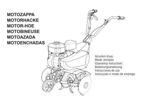
motozappa motorhacke motor-hoe motobineuse ... - Plantes et Jardins
motozappa motorhacke motor-hoe motobineuse ... - Plantes et Jardins
motozappa motorhacke motor-hoe motobineuse ... - Plantes et Jardins

Create successful ePaper yourself
Turn your PDF publications into a flip-book with our unique Google optimized e-Paper software.
MOTOZAPPA<br />
MOTORHACKE<br />
MOTOR-HOE<br />
MOTOBINEUSE<br />
MOTOAZADA<br />
MOTOENCHADAS<br />
.<br />
Istruzioni d'uso<br />
Mode d'emploi<br />
Operating instructions<br />
Bedienungsanweisung<br />
Instrucciones de uso<br />
Instrucçoes e modo de emprego
1 2<br />
3 4
5 6<br />
7
8 9<br />
1<br />
Costruttore<br />
Constructeur<br />
Manufacturer<br />
Baufirma<br />
Constructor<br />
Fabricante<br />
4<br />
Numero di serie articolo – Progressivo<br />
Numéro de série article - Progressif<br />
Serial number - Progressive<br />
Seriennummer Progressiv<br />
Número de serie artículo – Progresivo<br />
Numero de série - Progressivo<br />
2<br />
Modello<br />
Modèle<br />
Type<br />
Modell<br />
Modelo<br />
Modelo<br />
5<br />
Massa<br />
Masse<br />
Mass<br />
Gewicht<br />
Masa<br />
Massa<br />
3<br />
Anno di costruzione<br />
Année de construction<br />
Year of construction<br />
Baujahr<br />
Año de construcción<br />
Ano de fabricação<br />
6<br />
Potenza in Kw<br />
Puissance en Kw.<br />
Power in kW<br />
Leistung in Kw<br />
Potencia en Kw<br />
Potência em Kw
Etich<strong>et</strong>ta innesto R<strong>et</strong>romarcia<br />
Marche arrière<br />
Reverse drive<br />
Aufkleber für Rückwärtsgangeinschaltung<br />
Marcha atrás<br />
Marcha atrás<br />
Marcia avanti<br />
Marche avant<br />
Forward drive<br />
Fahrantrieb vorwärts<br />
Marcha adelante<br />
Velocidade para frente<br />
Leggere il manuale prima di usare la macchina<br />
Read the instructions manual before operating<br />
on the machine<br />
Lesen Sie die Gebrauchsanweisung vor der<br />
Inb<strong>et</strong>riebnahme<br />
Lire le mode d'emploi avant l'usage<br />
Antes de proceder a montar la màquina lea<br />
atentamente estas instrucciones<br />
Ler o manual das instruções antes do uso<br />
Etich<strong>et</strong>ta acceleratore<br />
Plaqu<strong>et</strong>te acceleration<br />
Label accelerator<br />
Gasaufkleber<br />
Etiqu<strong>et</strong>a acelerador<br />
Etiqu<strong>et</strong>a do acelerador<br />
Etich<strong>et</strong>ta indicazione filo r<strong>et</strong>romarcia<br />
Label for reverse wire<br />
Plaqu<strong>et</strong>te pour fil à marche arrière<br />
Aufkleber fuer rg-bowdenzug<br />
Etiqu<strong>et</strong>a indicación fhilo r<strong>et</strong>romarcia<br />
Etiqu<strong>et</strong>a indicaçâo de espia marchaatrás<br />
Attenzione: rotazione fresa<br />
Danger tiller rotation<br />
Achtung: frasenrotation<br />
Attention: danger rotation fraise<br />
Atencion: la fresa gira<br />
Atenção: rotação da fresa
Indice<br />
Introduzione<br />
Condizioni di utilizzazione<br />
Suggerimenti di sicurezza<br />
Trasporto<br />
Montaggio<br />
Regolazione<br />
Istruzioni d'uso<br />
Manutenzione<br />
Dati tecnici<br />
Rumore aereo<br />
Accessori<br />
Pericolo grave per<br />
l'incolumità dell'operatore e<br />
delle persone esposte.<br />
INTRODUZIONE<br />
Gentile cliente,<br />
lei ha acquistato una nuova attrezzatura. La ringraziamo per la fiducia accordata ai ns. prodotti e<br />
le auguriamo un piacevole utilizzo della sua macchina.<br />
Abbiamo creato queste istruzioni per I’uso allo scopo di assicurare, fin dall’inizio, un funzionamento privo d’inconvenienti.<br />
Seguite attentamente questi consigli, avr<strong>et</strong>e la soddisfazione di possedere per molto tempo una macchina<br />
che funziona a dovere. Le nostre macchine, prima di essere fabbricate in serie, vengono collaudate in maniera<br />
molto rigorosa e, durante la fabbricazione vera e propria, sono sottoposte a severi controlli. Ciò costituisce,<br />
per noi e per voi, la migliore garanzia che si tratta di un prodotto di riprovata qualità.<br />
Questa macchina é stata sottoposta a rigorosi test neutrali, nel paese d’origine, e risponde alle<br />
norme di sicurezza in vigore.<br />
Per garantire questo, é necessario utilizzare esclusivamente ricambi originali.<br />
L’utilizzatore perde ogni diritto di garanzia qualora vengono utilizzati ricambi non originali.<br />
Con riserva di variazioni tecnico-costruttive. Per informazioni e per ordinazioni di pezzi di ricambio si prega citare<br />
il numero di articolo e il numero di produzione.<br />
! Dati per l’identificazione (FIG. 1)<br />
L'<strong>et</strong>ich<strong>et</strong>ta con i dati della macchina e il numero di matricola è sul fianco sinistro della <strong>motozappa</strong>, sotto il <strong>motor</strong>e.<br />
Nota - Nelle eventuali richieste di Assistenza Tecnica o nelle ordinazioni delle Parti di Ricambio, citare sempre il<br />
numero di matricola della <strong>motozappa</strong> interessata.<br />
! Condizioni di utilizzazione - Limiti d'uso<br />
La <strong>motozappa</strong> è prog<strong>et</strong>tata e costruita per eseguire operazioni di zappatura del terreno. La <strong>motozappa</strong> deve lavorare<br />
esclusivamente con attrezzi e con ricambi originali. Ogni utilizzo diverso da quello sopra descritto è illegale;<br />
comporta, oltre al decadimento della garanzia, anche un grave pericolo per l'operatore e per le persone esposte.<br />
! Norme di sicurezza<br />
Attenzione: prima del montaggio e la messa in funzione leggere attentamente il libr<strong>et</strong>to istruzione.<br />
Le persone che non conoscono le norme di utilizzazione non possono usare la macchina.<br />
1 Impedire l’uso ai minori di 16 anni<br />
2 Controllare che i bambini stiano lontani. Si<strong>et</strong>e responsabili dei danni causati a terzi.<br />
3 Togliere i corpi estranei dal terreno prima di iniziare le operazioni di fresatura . Lavorare solo alla luce del<br />
giorno oppure in presenza di una buona illuminazione artificiale.<br />
4 Non m<strong>et</strong>tere in moto la macchina quando si è davanti alla fresa, nè avvicinarsi ad essa quando è in moto.<br />
ITALIANO 1
ITALIANO 2<br />
Tirando la cordina di avviamento del <strong>motor</strong>e, le frese e la macchina stessa devono rimanere ferme (se le frese girano intervenire sul registro di<br />
regolazione del tendicinghia).<br />
5 Durante il lavoro, per maggiore protezione, vanno indossate calzature robuste e pantaloni lunghi. Fare attenzione, perché il pericolo di ferirsi le<br />
dita o i piedi con la macchina in funzione è molto elevato. Camminare, non correre, durante il lavoro.<br />
6 Durante il trasporto della macchina e tutte le operazioni di manutenzione, pulitura, cambio degli attrezzi, il <strong>motor</strong>e deve essere spento.<br />
7 Allontanarsi dalla macchina non prima di aver spento il <strong>motor</strong>e.<br />
8 Non avviare la macchina in locali chiusi dove si possono accumulare esalazioni di carbonio.<br />
9 AVVERTENZA La benzina è altamente infiammabile: Non fare il pieno di benzina in locali chiusi né con il <strong>motor</strong>e in moto, non fumare e fare<br />
attenzione alle fuoriuscite di combustibile dal serbatoio. In caso di fuoriuscita non tentare di avviare il <strong>motor</strong>e, ma allontanare la macchina dall’area<br />
interessata evitando di creare fonti di accensione finchè non si sono dissipati i vapori della benzina. Rim<strong>et</strong>tere a posto corr<strong>et</strong>tamente i tappi del<br />
serbatoio e del contenitore della benzina.<br />
10 Attenzione al tubo di scarico. Le parti vicine possono arrivare a 80°. Sostituire i silenziatori usurati o dif<strong>et</strong>tosi.<br />
11 Non usare la <strong>motozappa</strong> su forti pendenze, potrebbe ribaltarsi. Sui pendii lavorare sempre trasversalmente, mai in salita o discesa ed<br />
esercitare la massima cautela nei cambi di direzione.<br />
12 Prima di iniziare il lavoro con la macchina procedere ad un controllo visivo e verificare che tutti i sistemi antinfortunistici, di cui essa è dotata,<br />
siano perf<strong>et</strong>tamente funzionanti. E’ severamente vi<strong>et</strong>ato escluderli o manom<strong>et</strong>terli. Sostituire i particolari danneggiati od usurati.<br />
13 Ogni utilizzo improprio, le riparazioni eff<strong>et</strong>tuate da personale non specializzato o l’impiego di ricambi non originali, comportano il decadimento<br />
della garanzia e il declino di ogni responsabilità della ditta costruttrice.<br />
! DISPOSITIVO DI SICUREZZA (Fig. 8) Tutte le motozappe sono dotate di dispositivo antinfortunistico. D<strong>et</strong>to dispositivo causa il disinnesto<br />
automatico della trasmissione quando si rilascia la relativa leva di comando (2-7).<br />
! NOTE PER IL LAVORO CON LA MOTOZAPPA A <strong>motor</strong>e avviato, appoggiare i coltelli sul terreno e, tenendo saldamente la <strong>motozappa</strong>,<br />
infilare nel terreno il braccio del timone. Tirare la leva della frizione sulla stegola per far pen<strong>et</strong>rare la fresa nel terreno. Sollevando leggermente la fresa mediante<br />
le stegole, la <strong>motozappa</strong> si muove in avanti. Il braccio del timone durante il lavoro deve rimanere sempre infilato nel terreno. Applicazioni: Lavorazione<br />
di terreni leggeri o di media pesantezza. Lavorazione del terreno (fresatura/sminuzzamento). Dissodamento del terreno (eliminazione infestanti).<br />
Incorporamento di compost o fertilizzanti, ecc. Attenzione: La <strong>motozappa</strong> non è adatta per la lavorazione di terreni ricoperti di cotica erbosa compatta/<br />
prato. Se ne sconsiglia inoltre l'uso sui terreni pi<strong>et</strong>rosi.<br />
! TRASPORTO<br />
Per la movimentazione è previsto l'uso di carrello elevatore. Le forche, allargate al massimo consentito, vanno inserite negli appositi spazi del pall<strong>et</strong>. La<br />
massa della macchina è indicata nella <strong>et</strong>ich<strong>et</strong>ta della marcatura e riportata nei dati tecnici.<br />
! MONTAGGIO DELLA MOTOZAPPA (Fig. 2) La <strong>motozappa</strong> viene consegnata a destinazione, salvo accordi diversi, smontata e sistemata<br />
in un adeguato imballaggio. Per compl<strong>et</strong>are il montaggio della <strong>motozappa</strong> osservare la seguente procedura. RUOTA DI TRASFERIMENTO: Inserire<br />
la ruota di trasferimento e fissarla con la spilla a R presente nella busta accessori. Ruota in posizione di trasporto (1) ed in posizione di lavoro (2). TI-<br />
MONE: Inserire il timone (3) in corrispondenza del foro centrale, bloccare con la rondella (4) e con la spilla a R (5) presenti nella busta accessori.
! MONTAGGIO STEGOLA (Fig. 3) Montare la stegola (3) sulla <strong>motozappa</strong> tramite le risp<strong>et</strong>tive viti e rondelle. Nel foro superiore usare la vite<br />
M8x65 (4), rondelle (5) e dado (6) presente nella busta accessori. Nel foro inferiore avvitare la vite M8 (7) con rondella (8). Dall’altra parte fermare il<br />
passafilo (9) con la vite M8 (7).<br />
! ! MONTAGGIO CAVI COMANDO (FIG. 4 e FIG. 5) I due cavi sono gia’ montati alla macchina e occorre collegarli alle risp<strong>et</strong>tive leve<br />
dopo averli fatti passare entrambi nel passafilo (Fig. 3 part.9) della stegola. (Fig. 4) MARCIA AVANTI: il filo va collegato alla leva innesto (1) inserendo<br />
il terminale (2) nel foro (3) della leva. Dopo aver dato un deciso strappo alla guaina (4), passare il filo nel foro tagliato del nasello (5) lasciando il registro<br />
e i dadi come in figura. (Fig. 5) RETRO MARCIA: il filo e’contrassegnato dalla <strong>et</strong>ich<strong>et</strong>ta R (5) e va collegato alla leva r<strong>et</strong>romarcia (1) inserendo il<br />
terminale (2) nel foro della leva. Dopo aver dato un leggero strappo alla guaina (3) passare il filo nel foro tagliato del nasello (4) lasciando il registro e i<br />
dadi come in figura.<br />
! ! MONTAGGIO DELLE FRESE A ZAPPETTE (Fig. 7) 1. Pulire i mozzi delle frese e l’albero porta-frese; spalmare una piccola quantità di<br />
grasso per facilitare il montaggio e la futura rimozione delle frese. 2. Versione con <strong>motor</strong>e Intek (fig. 7/A): inserire la fresa (1) badando che i coltelli<br />
abbiano l’affilatura rivolta verso l’anteriore della macchina e bloccare con due spinotti (2), aggiungere l’allargamento fresa (3) e fissare anche quest’ultimo<br />
con uno spinotto (2). Infine bloccare il disco proteggipiante (4) con vite (5) e dado (6). Rip<strong>et</strong>ere la stessa operazione per la fresa sull’altro lato.<br />
Versione con altri <strong>motor</strong>i (fig. 7/B): la fresa (1) risulta già montata con nr. 2 viti ed altr<strong>et</strong>tanti dadi, quindi occorre solo aggiungere l’allargamento fresa<br />
(3), bloccarlo con uno spinotto (2) e fissare il disco proteggipiante (4) con vite (5) e dado (6). Rip<strong>et</strong>ere la stessa operazione per la fresa sull’altro lato. N.B.<br />
Occorre montare lo spinotto come raffigurato nel quadr<strong>et</strong>to centrale, cioè con il fermo di protezione girato nel senso di<br />
rotazione delle frese, in modo tale da impedire che durante il lavoro si possa aprire.<br />
! REGISTRAZIONE DEI COMANDI (Fig. 4 - Fig. 6) Attenzione! La fresa deve iniziare a girare non prima di avere agito sui risp<strong>et</strong>tivi<br />
comandi. Questo si ottiene intervenendo sui registri dei fili della stegola. Inoltre la leva che comanda la marcia di zappatura (Fig.4 part.1) deve avviare<br />
la fresa solo dopo aver compiuto m<strong>et</strong>à della propria corsa. Quando la leva è a fine corsa cioè in posizione di lavoro, la molla di carico del tendicinghia<br />
marcia avanti (Fig.6 part.1) si deve allungare di circa 13-18 mm. Se il registro della stegola (Fig.4 part.4) non è sufficiente ad ottenere d<strong>et</strong>te condizioni,<br />
provvedere a regolare il registro 2 (Fig.6).<br />
! ISTRUZIONI D'USO<br />
Dopo le operazioni di montaggio e regolazione la <strong>motozappa</strong> è pronta per lavorare.<br />
ATTENZIONE. Prima di avviare il <strong>motor</strong>e controllare sempre che la macchina sia in perf<strong>et</strong>te condizioni di funzionamento.<br />
- Istruzioni Motore: Leggere attentamente il libr<strong>et</strong>to istruzioni allegato del relativo <strong>motor</strong>e.<br />
- Non modificare la taratura del regolatore di velocità di rotazione del <strong>motor</strong>e e non far raggiungere ad esso una condizione di sopravvelocità.<br />
- Regolare il manubrio all’altezza più adatta al lavoro da eseguire.<br />
- Messa in moto del <strong>motor</strong>e (Fig.8) Aprire il rubin<strong>et</strong>to del carburante (per i <strong>motor</strong>i provvisti), posizionare su START la lev<strong>et</strong>ta dell’acceleratore<br />
posto sul manubrio (part.1). Se il <strong>motor</strong>e è freddo, azionare il dispositivo di starter sul carburatore, afferrare la maniglia di avviamento e dare uno<br />
strappo energico. Avviato il <strong>motor</strong>e riportare, dopo i primi scoppi, lo starter nella posizione di riposo.<br />
- Marcia avanti: impugnare il manubrio, tirare la leva frizione (part.2) per tutta la sua corsa.<br />
- Marcia indi<strong>et</strong>ro: (Fig.8) rilasciare la leva frizione (part.2) e tirare verso di sè la leva posta sul manubrio (7).<br />
ITALIANO 3
ITALIANO 4<br />
- Questa <strong>motozappa</strong> è prog<strong>et</strong>tata per ridurre al minimo le emissioni di vibrazioni e rumore, tuttavia è buona norma intervallare lavori di lunga durata<br />
con piccole pause.<br />
- Fine lavoro : terminato il lavoro, per arrestare il <strong>motor</strong>e, portare la leva acceleratore (Fig.8 part.1) nella posizione di stop.<br />
! SOSTITUZIONE OLIO DEL CAMBIO (solo per <strong>motor</strong>i/cambi a caldo) (Fig. 9) In linea di massima si dovrebbe sostituire l'olio<br />
ogni 100 ore di lavoro. (Viscosità olio SAE 80). Cambio olio: a) Allentare il tappo a vite. - b) Collocare la macchina in posizione inclinata e aspirare l'olio tramite<br />
una siringa. - c) Introdurre l'olio nuovo nella quantità di circa 0,5 lt. Per controllare il giusto livello è necessario inclinare la macchina; l'olio dovrà iniziare ad<br />
uscire dal foro poco prima che la macchina (con il punto A) tocchi terra. - d) Richiudere il foro di riempimento con il tappo a vite.<br />
! RIMESSAGGIO E MANUTENZIONE PERIODICA<br />
Mantenere serrati tutti i dadi, i bulloni e le viti per garantire il funzionamento della macchina nelle condizioni di sicurezza. Lasciar raffreddare la macchina<br />
prima di immagazzinarla e comunque non riporla con benzina nel serbatoio all’interno di un edificio, dove i vapori possono raggiungere una fiamma libera<br />
o una scintilla. Per ridurre il pericolo di incendio mantenere il <strong>motor</strong>e, il silenziatore e la zona di immagazzinamento della benzina liberi da foglie, erba e grasso<br />
in eccesso.<br />
! DESCRIZIONE DEI COMANDI (Fig. 8) 1. Man<strong>et</strong>ta comando acceleratore a mano - 2. Leva comando marcia di zappatura (dispositivo<br />
antinfortunistico) - 3. Maniglia per avviamento a strappo (dispositivo autoavvolgente) - 4. Timone per regolazione fresatura (unica posizione) - 5. Frese<br />
(con allargamento) - 6. Riparo fresa - 7. Leva comando RM<br />
! CARATTERISTICHE TECNICHE Motore: per informazioni vedere la pubblicazione specifica. Trasmissione: Primaria a cinghia - Secondaria<br />
a catena. Fresa: a zapp<strong>et</strong>te intercambiabili per larghezza di lavoro di 50 cm e 80 cm, compl<strong>et</strong>a di carter di protezione. La velocità massima di rotazione<br />
della fresa è di 140 giri/min. circa. Cambio: marcia avanti o marcia avanti + r<strong>et</strong>romarcia. Peso: Peso della <strong>motozappa</strong> compl<strong>et</strong>a di fresa da 50 cm, circa 50<br />
kg; con fresa da 80 cm, circa 55 kg. Dimensioni: Lunghezza massima 1,35 m. Larghezza massima 0,50 m - 0,80 m. Altezza 1,00 m. Dimensioni imballaggio:<br />
lunghezza 0,800 m - larghezza 0, 530 m - altezza 0,690 m.<br />
! RUMORE AEREO E VIBRAZIONI Valore di pressione acustica al posto di lavoro secondo EN 709 L A e q = 88,2 dB (A). Vibrazioni alle stegole<br />
secondo EN 709 e ISO 5349. Valore medio rilevato = 7,61 m/s 2 .<br />
! ! ACCESSORI - ATTREZZI UTILIZZABILI Rincalzatore ad ali fisse con attacco, si usa per fare dei solchi nel terreno prima della semina.<br />
Il rincalzatore si fissa alla macchina, al posto dello sperone, e si blocca con una spina a R. - Risanatore prato a molle.
List of contents<br />
Introduction<br />
Conditions of use<br />
Saf<strong>et</strong>y measures<br />
Instructions for operating<br />
Transport<br />
Assembly<br />
Regulating<br />
Maintenance<br />
Technical D<strong>et</strong>ails<br />
Noise<br />
Accessories<br />
Serious risk for operator<br />
and bystander saf<strong>et</strong>y.<br />
Introduction<br />
Dear Customer:<br />
Thank you for your confidence in purchasing our products. We wish you to enjoy using our<br />
machines.<br />
The following working instructions have been issued to ensure you a reliable running from the beginning. If you<br />
carefully follow such information the machine will operate with compl<strong>et</strong>e satisfaction have a long service life.<br />
Our machines are tested under the most severe conditions before being put into production and are subjected to<br />
strict continuous tests during manufacturing stages.<br />
The present unit has been tested in the country of origin by independent testing authorities in<br />
accordance with strict work norms and saf<strong>et</strong>y standards.<br />
When required, only original spare parts must be used to maintain guaranteed function and<br />
saf<strong>et</strong>y levels.<br />
The operator forfeits any claims which may arise, if the machine shows to be fitted with<br />
components other than original spare parts.<br />
Subject to changes in design and construction without notice.<br />
For any questions or further information and spare part orders,we need to be informed of the unit serial number<br />
printed on the side of the machine.<br />
! IDENTIFICATION DATA (Fig. 1)<br />
The tag plate with the machine data and Serial N° is on the left side of the cultivator under the engine.<br />
Note - Always state your <strong>motor</strong> cultivator serial number when you need Technical Service or Spare Parts.<br />
! CONDITIONS OF USE AND LIMITATIONS OF USE<br />
This <strong>motor</strong>-<strong>hoe</strong> is designed and built to <strong>hoe</strong> the land. The <strong>motor</strong>-<strong>hoe</strong> must only be used with original equipment and<br />
spares. Any use other than those described above is prohibited and will involve, in addition to cancellation of the<br />
warranty, serious risk for the operator and bystanders.<br />
! SAFETY PRECAUTIONS<br />
Attention: Before assembly and putting into operation, please read the operating instruction<br />
carefully. Persons not familiar with these instructions should not use the machine.<br />
1 Persons under 16 should not be allowed to use the machine.<br />
2 When operating the machine, the user should ensure that no others, particularly children, are standing<br />
in the area. Please, remember that you are responsible for the safe operating of your machine vis-a-vis<br />
third persons.<br />
3 Before starting to mill, remove any foreign bodies from the soil. Work only in daylight or in good artificial<br />
light.<br />
ENGLISH 5
ENGLISH 6<br />
4 Do not start the machine if standing in front of the rotary cutter, neither g<strong>et</strong> near the machine when working. If pulling the starter short rope, the<br />
rotary cutter and the machine have to standstill (if rotation is experienced, take action on the belt str<strong>et</strong>cher control nut).<br />
5 During working operations, for protection purposes, it is recommended to wear technical/strong s<strong>hoe</strong>s and long trousers. Be careful , because<br />
when machine is operating the danger to be wounded in the toes or fe<strong>et</strong> is really high. Walk, never run with the machine.<br />
6 During the machine transport and all the maintenance, cleaning, equipment change operations, the engine must be switched off.<br />
7 Before leaving the machine, please switch the engine off.<br />
8 Do not switch the machine on in closed rooms/areas where you can have carbon monoxide exhalations.<br />
9 WARNING !! The p<strong>et</strong>rol/gasoline is highly inflammable: Don’t fill the tank neither in closed areas, nor when engine is on, don’t smoke and be<br />
careful to the p<strong>et</strong>rol/gasoline loss from the tank. In case of leak, don’t try to switch the engine on but move the machine away from the area in order<br />
to avoid ignition source until the gasoline vapours fade away. Re-place the tank caps and the gasoline box.<br />
10 Keep attention to the exhaust pipe. The parts near the pipe can reach 80°C.<br />
Replace the defective and/or worn out silencers Burn hazards !!!.<br />
11 Don’t use the <strong>motor</strong><strong>hoe</strong> on steep slopes: it could overturn!. On slope it is recommended to work crosswise, neither in slope nor in descent and<br />
be vary careful during any change of direction.<br />
12 Before putting the machine into operations, check it visually and make sure all the accident prevention measures are working. It is absolutely<br />
forbidden to exclude and/or to tamper with them. Replace worn or damaged elements.<br />
13 In case the machine is incorrectly used, and/or the repairs are performed by non-authorized technical staff, and/or fitted by equispare parts<br />
other then original ones: any use other than that described above is prohibited and will involve the cancellation of the warranty and the refuse all<br />
responsability from the manufacturer.<br />
! SAFETY FEATURE (Fig. 8) All <strong>motor</strong>-<strong>hoe</strong>s are provided with a saf<strong>et</strong>y feature which acts. The device causes the transmission to disconnect<br />
automatically anytime the respective control lever is released (2-7).<br />
! NOTES ON WORK WITH THE MOTOR-HOE With the engine running, rest the tines on the ground, and firmly holding the <strong>motor</strong>-<strong>hoe</strong>, insert<br />
the tool bar arm into the soil. Pull the clutch lever on the handlebar to allow the disks to bite into the soil. The <strong>motor</strong>-<strong>hoe</strong> will move forwards when the<br />
handlebars are used to slightly lift the disks. The tool bar arm must always remain in the soil during work. Uses: Light or medium textured soil working. Soil<br />
working (<strong>hoe</strong>ing/breaking-up). Soil tillage (weeding). Ploughing in compost or fertilizers, <strong>et</strong>c. Attention: The <strong>motor</strong>-<strong>hoe</strong> is unsuitable for working in soils<br />
covered by thick grass/lawns. It is also unadvisable to use the implement on stony soils.<br />
! TRANSPORT A forklift truck should be used to move the machine. The forks should be opened as far as possible and inserted into the pall<strong>et</strong>. The<br />
weight of the machine is given on the Manufacturer's data plate tog<strong>et</strong>her with the other technical information.<br />
! HOW TO ASSEMBLE YOUR MOTOR-HOE (Fig. 2) Unless otherwise agreed, the <strong>motor</strong> cultivator is delivered disassembled and<br />
placed in a packing case. For assembly to be compl<strong>et</strong>ed, the step/by/step procedure is as follows. Transport wheel :insert the transport wheel and fix it<br />
with the R-pin you can find the spares envelope. Wheel shown on transport position (1) and on working one (2) . Shaft : position the shaft (3) making it to<br />
correspond to the central slot, block it with the washer (1) and with the R-pin (2) , you can find both parts in the accessories envelope.
! HANDLEBAR ASSEMBLY : ( Fig. 3) : Assemble the handlebar (3) on the tiller using the corresponding screws and washers. For the<br />
upper slot use the screw M8x65 (4), washers (5) and nut (6) , you can find the parts in the accessories envelope. Screw the M8 screw (7) and the<br />
washer (8) into the lower slot. On the other side stop the fairlead (9) with screw M8 (7).<br />
! CONTROL CABLES ASSEMBLY : (Fig. 4 - Fig. 5) You can find the 2 cables already assembled in the machine so you need to link<br />
them to the respective levers , after having made them to pass into the handlebar fairlead (Fig. 3 part 9). Fig. 4 – Forward speed : the cable has to be<br />
linked to the forward lever (1), making the part (2) into the lever slot (3). After having performed a slight jerk to the protecting coverage (4) , pass the<br />
cable into the cut slot of the nib (5) . Leave the adjuster and the nuts as they are in the picture. Fig. 5 : Reverse speed : the cable is marked with the “R”<br />
sticker (5) and it has to be linked to the reverse lever (1) inserting the part (2) into the lever slot. After having performed a slight jerk to the protecting<br />
coverage (3) , pass the cable into the cut slot of the nib (4) . Leave the adjuster and the nuts as they are shown in the picture.<br />
! ! MOUNTING THE HOE TILLER (Fig. 7) 1. Clean the tiller hubs and the tiller-shaft; apply some grease to make mounting and tiller future<br />
removal easier. - 2. Intek engine model (fig. 7/A): insert the rotavator (1) making attention the knives have the sharpening side turned to the front<br />
part of the machine and block the rotavator with two pins (2) assembling the extra-wide tines (3) and fix it with 1 pin as well (2). Then block the tree saver<br />
disk (4) with 1 screw (5) and 1 nut (6). Repeat the same operation for the rotavator on the other machine side. Other engines (fig. 7/B): the rotavator<br />
(1) is already assembled with nr. 2 screws and the same number of nuts so you only need to assemble the extra-wide tines (3) and block it with 1 pin (2)<br />
and fix the tree saver disk (4) with 1 screw (5) and 1 nut (6). Repeat the same operation for the rotavator on the other machine side. N.B. = please note it<br />
is necessary to assemble the pin as shown in the picture placed in the centre of the page, i.e. , with the protection stopping<br />
device turned in the same direction the rotavators are turning, in order to avoid the pin to open during working operations.<br />
! ! CONTROL ADJUSTMENT : (Fig. 4 - Fig. 6) Attention ! The rotavator has to start working only after having operated on the control<br />
levers. such operation can be performed by acting on the handlebar cables register. Furthermore the lever controlling the digging speed ( Fig. 4 part<br />
1) should start the rotavator only after having perfomed half its way. when the lever is end its way , i.e. on working operation , the belt str<strong>et</strong>cher loadspring<br />
for forward speed (Fig. 6, part 1) should be extended for about 13-18 mm. If the handlebar register (Fig. 4 part 4) is not enough to obtain am<br />
conditions , please go on adjusting the register (2) , Fig. 6.<br />
! INSTRUCTIONS<br />
Following the assembly & adjustment operations the <strong>motor</strong>-<strong>hoe</strong> is ready to start working.<br />
ATTENTION ! Before switching the engine on, carefully check if the <strong>motor</strong>-<strong>hoe</strong> is in perfect good repair.<br />
- Engine instructions: Carefully read the istructions bookl<strong>et</strong> anclosed to the relevant engine.<br />
- Do not change the calibration of the speeds control rotation device of the engine in order not to over-speed it.<br />
- Adjust the handlebar to the requested position/height:<br />
- How to switch the engine on (Fig.8): Open the fuel cap (for the engine equipped like this), push to START the accelerator lever on the handlebar<br />
(part.1). If the engine is cold, operate the starte device on the carbur<strong>et</strong>tor, bring the starter handle and pull energ<strong>et</strong>ically.<br />
When the engine is on, after some bursts/bangs, put the starter again at rest position,<br />
- Forward drive: pull the clutch lever (part.2) to the end of its way.<br />
- Reverse speed: leave the clutch lever (Fig.8) (part.2) and pull towards ourselves the lever on the handlebar (3).<br />
ENGLISH 7
ENGLISH 8<br />
- The present tiller has been projected in order to lower to the minimum the vibrations and noise levels. Anyhow we can advise you to stop working any<br />
now and then in case you would need to perform/work for a long period.<br />
- Stop working operation : To stop the work, switch the engine off, bring the accelerator lever (Fig. 8 part 1) into stop position.<br />
! GEAR BOX OIL CHANGE (only when engine/gear box is working using a hot device) (Fig. 9) As a general rule the oil<br />
should be changed after every 100 work hours (oil viscosity SAE 80). To change oil: a) Unscrew the srew cap. - b) Tilt the machine and intake the oil through<br />
a syringe. - c) Pour in about 0,5 l. of new oil. Tilt the machine to check that level is correct. The oil should begin to flow from the hole just before the machine<br />
touches the ground (with point A) - d) Replace the filler screw cap.<br />
! GARAGING AND SCHEDULED MAINTENANCE<br />
Keep attention that all the nuts ,screws and bolts are tightened in order to guarantee a good machine working on saf<strong>et</strong>y conditions. Leave the machine to<br />
cool before garaging anyhow don’t room it if the tank contains still contains some fuel as the vapours could reach some blazes or sparks. To lower the fire<br />
danger , keep the engine , the silencer and the fuel area free from leaves , grass or greasy substances.<br />
! DESCRIPTION OF CONTROLS (Fig. 8) 1. Throttle lever - 2. Hoeing gear control lever (saf<strong>et</strong>y feature) - 3. Pull-out handle (self-winding<br />
device) - 4. Tilling adjustment drawbar (single position) - 5. Cultivator blade (with enlargement) - 6. Hoe shield - 7. Reversing lever<br />
! TECHNICAL SPECIFICATION Engine: consult the specific publication for information. Transmission: primary by belt, secondary by chain.<br />
Tiller: fitted with interchangeable <strong>hoe</strong>s. Working width 50 cm and 80 cm. The highest speed of rotation of the tiller is about 140 R.P.M. Transmission : single<br />
speed or single speed+reverse speed. Weight: weight of <strong>motor</strong>-cultivator in the working order provided with 50 cm <strong>hoe</strong>-tiller: 50 kg approx. , with 80 cm<br />
<strong>hoe</strong>-tiller 55 kg approx. Max length: 1,350 m. Max width: 0,500 - 0,800 m. Height: 1,000 m. Package dimensions: long 0,800 m - wide 0,530 m - high 0,690<br />
m.<br />
! NOISE AND VIBRATION LEVEL Noise level when working in compliance with EN 709 L A e q = 88,2 dB (A). Handlebar vibration in compliance<br />
with EN and ISO 5349. Level d<strong>et</strong>ected = 7,61 m/s 2 .<br />
! ! ! ACCESSORIES - ATTACHMENTS Ridging body with hitch. The ridging body is used to prepare furrows in the soil before sowing. The<br />
ridging unit is fixed to the machine in place of the headstock and is locked by means of a pin and a lock pin. - De-thatcher.
Inhaltsverzeichnis<br />
Einleitung<br />
Einsatzbedingungen<br />
Sicherheitsmaßnahmen<br />
Bedienungshinweise<br />
Transport<br />
Montage<br />
Einstellung<br />
Wartung<br />
Technische Daten<br />
Lärmemission<br />
Zubehörteile<br />
Schwere Gefahr für die<br />
Unversehrtheit des<br />
Bedieners und der<br />
Personen in der Reichweite<br />
der Maschine.<br />
Einleitung<br />
Verehrter Kunde,<br />
Sie haben ein neues Gerät erworben. Wir bedanken uns für Ihr Vertrauen, das Sie in unsere<br />
Qualitätsprodukte s<strong>et</strong>zen und wünschen Ihnen viel Freude beim Arbeiten mit Ihrem neuen<br />
Gerät. Um eine zuverlässige Inb<strong>et</strong>riebnahme von vornherein zu gewährleisten haben wir diese<br />
B<strong>et</strong>riebsanleitung geschaffen. Wenn Sie die folgenden Hinweise genau beachten, wird Ihr Gerät st<strong>et</strong>s zu Ihrer<br />
vollsten Zufriedenheit arbeiten und eine lange Lebensdauer besitzen. Unsere Geräte werden vor der<br />
Serienherstellung unter härtesten Bedingungen erprobt und während der Fertigung selbst ständigen strengen<br />
Kontrollen unterzogen. Dies gibt uns die Sicherheit und Ihnen die Gewähr, st<strong>et</strong>s ein ausgereiftes Produkt zu<br />
erhalten. Dieses Gerät wurde im Herstellerland durch neutrale Prüfstellen nach strengen Arbeitsund<br />
Sicherheitsnormen geprüft. Zur Aufrechterhaltung dieser Funktions- und<br />
Sicherheitsgewähr dürfen im Bedarfsfall nur Originalteile des Herstellers verwend<strong>et</strong> werden.<br />
Der Benützer verliert alle evtl. bestehenden Ansprüche, wenn er das Gerät mit anderen als den<br />
Originalersatzteilen verändert. Konstruktions-und Ausführungsänderungen vorbehalten. Bei Rückfragen<br />
oder Ersatzteilbestellungen die Artikelnummer und die Erzeugnisnummer angeben.<br />
! KENNZEICHNUNGSANGABEN (Abb. 1) Das Schild mit den Maschinendaten und der<br />
Seriennummer befind<strong>et</strong> sich auf der linken Seite der Motorhacke, und zwar unter dem Motor. Hinweis- Bei<br />
eventuellen technischen Beratungsfragen oder bei Ersatzteilbestellungen, die Kennummer der Maschine<br />
angeben.<br />
! EINSATZBEDINGUNGEN - EINSATZGRENZEN Die Motorhacke ist entwickelt und gebaut worden,<br />
um auf Bodenflächen Hackenarbeiten auszuführen.. Die Motorhacke darf nur mit Original-Geräten und Original-<br />
Ersatzteilen arbeiten. Jede Benutzung, die von der hier beschriebenen abweicht, ist nicht gestatt<strong>et</strong>. Es führt nicht<br />
nur zum Verfall der Garantiegewährung, sondern stellt auch eine große Gefahr für den Bediener und alle<br />
Personen in der Reichweite der Maschine dar.<br />
! SICHERHEITS-MAßNAHMEN Achtung: Vor der Montage und Inb<strong>et</strong>riebnahme die<br />
Bedienungsanweisung unbedingt beachten. Personen, die mit der Gebrauchsanweisung nicht<br />
vertraut sind, dürfen das Gerät nicht benützen.<br />
1 Jugendlichen unter 16 Jahren ist der Gebrauch zu verbi<strong>et</strong>en.<br />
2 Sicherstellen, dass keine Kinder in der Nähe sind. Sie sind für die Schäden verantwortlich, die Dritten<br />
entstehen.<br />
3 Bevor man mit dem Fräsen beginnt, Fremdkörper im Boden entfernen.<br />
4 Die Maschine nicht in B<strong>et</strong>rieb nehmen, wenn man vor der Fräse steht. Nähern Sie sich dieser nicht,<br />
wenn sie läuft. Wenn man die Zündschnur des Motors zieht, dürfen die Maschine und die Fräse sich noch<br />
nicht bewegen.<br />
DEUTSCH 9
DEUTSCH 10<br />
5 Während der Arbeit sollte man zum besseren Schutz festes Schuhwerk und lange Hosen tragen. Vorsichtig vorgehen, weil eine große Gefahr<br />
besteht, sich bei laufender Maschine die Finger oder die Füße zu verl<strong>et</strong>zen.<br />
6 Während des Transports der Maschine und aller Wartungsarbeiten, dem Reinigen und dem Wechsel der Geräte muss der Motor immer<br />
abgeschalt<strong>et</strong> sein.<br />
7 Entfernen Sie sich erst dann von der Maschine, wenn man den Motor abgeschalt<strong>et</strong> hat.<br />
8 Die Maschine nicht in geschlossenen Räumen laufen lassen, wo die entstehenden Abgase sich anhäufen könnten.<br />
9 HINWEIS Benzin ist ein feuergefährlicher Stoff: Nicht in geschlossenen Räumen und nicht bei laufendem Motor tanken, nicht rauchen und auf<br />
den aus dem Tank auslaufenden Treibstoff achten. Bei auslaufendem Treibstoff nicht versuchen, den Motor zu starten, sondern die Maschine<br />
von der b<strong>et</strong>roffenen Stelle entfernen und vermeiden, Zündquellen zu erzeugen, bis die Benzindämpfe nicht abgezogen sind. Die Stopfen des<br />
Tanks und des Benzinbehälters wieder ordentlich aufschrauben.<br />
10 Auf das Auspuffrohr achten. Die nahe am Auspuff liegenden Teile können bis zu 80° heiß werden. Verschlissene oder defekte Auspufftöpfe<br />
ers<strong>et</strong>zen.<br />
11 Das Gerät nicht auf Gelände mit starkem Gefälle benutzen: Er könnte umkippen. Auf Gefälle sollte man immer in der Querrichtung arbeiten,<br />
nie bergauf oder bergab. Beim Gangschalten sehr vorsichtig vorgehen.<br />
12 Bevor man die Arbeit mit der Maschine beginnt, eine Sichtprüfung vornehmen und sicherstellen, dass alle Unfallschutzvorkehrungen, mit<br />
denen sie versehen ist, vollkommen funktionstüchtig sind. Es ist streng verboten, diese zu umgehen oder zu manipulieren.<br />
13 Jede bestimmungswidrige Benutzung, nicht vom Fachmann vorgenommene Reparaturen oder die Benutzung von Ersatzteilen, die kein<br />
Original sind, führen zum Verfall der Garantie und dem Verlust der Herstellerhaftung.<br />
! SICHERHEITSVORRICHTUNG (Abb. 8) Alle Motorhacken sind mit einer Sicherheitsvorrichtung auf Basis der Unfallschutzmassnahmen<br />
versehen. Durch B<strong>et</strong>ätigung des Bedienungshebels wird die Antriebswelle automatisch ausgeschalt<strong>et</strong>. (2-7)<br />
! ! HINWEISE ZUM ARBEITEN MIT DER HACKE (ARBEITS - FUNKTION) Bei laufendem Motor Hackmesser auf die Erde aufs<strong>et</strong>zen,<br />
das Gerät festhalten und den Bremssporn in den Boden drücken. Kupplungshebel am Holm spannen, die Hackmesser graben sich nun in die Erde. Wenn<br />
Sie j<strong>et</strong>zt die Hacke an den Holmen <strong>et</strong>was anheben, arbeit<strong>et</strong> das Gerät vorwärts. Der Bremssporn soll beim Arbeiten immer in der Erde sein.<br />
Anwendungsbereiche: Bodenbearbeitungsgerät für leichte bis mittelschwere Böden. Bodenbearbeitung (Fräsen/Feinkrümelung). Bodenlockerung<br />
(Unkrautentfernung). Einarbeiten von Kompost oder Dünger usw. Häufeln. Achtung: Gerät eign<strong>et</strong> sich nicht zum Umarbeiten von Böden mit einer festen<br />
Grasnarbe/Wiese. Desweiteren wird vom Einsatz in grobsteinigen Gelände abgeraten!<br />
! TRANSPORT Für den Transport der Maschine ist ein Gabelstapler zu benutzen. Die auf die höchstzulässige Breite gestellten Gabeln sind in den<br />
Raum unter der Pal<strong>et</strong>te einzufahren. Das Gewicht der Maschine steht auf dem Typenschild und in den technischen Daten.<br />
! MONTAGE DER MOTORHACKE (Abb. 2) Die Motorhacke wird in "Teilmontiertem" Zustand und in einer dazu geeign<strong>et</strong>en Verpackung<br />
geliefert. Zum endgültigen Zusammenbau wie folgt verfahren. TRANSPORTRÄDER - Das Transportrad einstecken und mit dem Sicherungsstift<br />
befestigen,das im Zubehörbeutel vorhanden ist. Transportposition(1) Arbeitsposition (2). BREMSSPORN - Den Bremssporn (3) im das Zentralloch<br />
stecken,mit der Unterlegscheibe (4)und dem Sicherungsstift (5)blockieren,die im Zubehörbeutel vorhanden sind.<br />
! HOLMMONTAGE (Abb. 3) Dem Holm (3) auf der Motorhacke mit den entsprechenden Schrauben und Scheiben montieren.Im oberen Loch d
die Schraube M8x65 (4),die Scheiben(5) und die Mutter (6) benutzen,die sich im Zuberhörbeutel befinden. Im unteren Loch die Schraube M8 (7) mit der<br />
Scheibe(8) eindrehen. Von der anderen Seite die Kabeldurchführung(9) mit der Schraube M8(7) befestigen.<br />
! ! MONTAGE DER BOWDENZÜGE (Abb.4 - Abb.5) Die beiden Bowdenzüge sind schon an der Maschine montiert und man muss sie an<br />
den entsprechenden Hebeln anschließen,nachdem man sie beide durch die Kabeldurchführung (Abb.3 Teil 9) des Holms gesteckt hat. Abb.4<br />
VORWÄRTSGANG: Der Bowdenzug ist an den Einschalthebel(1) anzuschließen,indem man Kabelschuh (2) in das Loch(3) des Hebels steckt.<br />
Nach einem leichten Zug an der Kabelhülle (4) den Bowdenzug in das Loch stecken, das man in den Vorsprung (5) geschnitten hat, wobei man die<br />
Einstellvorrichtung und die Muttern wie in der Abbildung angeordn<strong>et</strong> lässt. Abb.5 RÜCKWÄRTSGANG : Der Bowdenzug ist mit dem Etik<strong>et</strong>t R (5)<br />
versehen und ist an den Hebel des Rückwärtsgangs (1) anzuschließen, indem man den Kabelschuh (2) in das Loch des Hebels steckt. Nach einem<br />
leichten Zug an der Kabelhülle (3) den Bowdenzug in das Loch stecken, das man in den Vorsprung (4) geschnitten hat, wobei man die Einstellvorrichtung<br />
und die Muttern wie Abbildung angeordn<strong>et</strong> lässt.<br />
! MONTAGE DER HACKMESSER (HACKFRÄSEN) (Abb. 7) 1. Die Naben der Fräsen und der Fräsentragewelle reinigen; eine geringe<br />
F<strong>et</strong>tmenge auftragen, um die Montage und das künftige Ausbauen der Fräsen zu vereinfachen. 2. Version mit Motor Intek (Abb. 7/A): Die Fräse<br />
(1) einstecken und darauf achten, dass der Schliff der Messer zur Vorderseite der Maschine zeigt, und mit zwei Splinten (2) blockieren. Die<br />
Fräsenerweiterung (3) hinzufügen und auch l<strong>et</strong>ztere mit einem Split (2) befestigen. Schließlich die Pflanzenschutzscheibe (4) mit der Schraube (5) und<br />
der Mutter (6) blockieren. Den gleichen Vorgang für die Fräse auf der anderen Seite wiederholen. Version mit anderen Motoren (Abb. 7/B): Die<br />
Fräse (1) ist schon mit 2 Schrauben und ebenso vielen Muttern montiert, folglich ist nur die Fräsenerweiterung (3) zu montieren, sie mit einem Splint (2)<br />
zu blockieren und dann die Pflanzenschutzscheibe (4) mit Schraube (5) und Mutter (6) blockieren. Den gleichen Vorgang für die Fräse auf der anderen<br />
Seite wiederholen. Anm.: Der Splint ist so zu montieren, wie es im Kasten in der Mitte dargestellt ist, d.h. mit der Schutzarr<strong>et</strong>ierung<br />
in der Richtung gedreht, die der Fräsenrotation entspricht, damit verhindert wird, dass die Fräse sich bei der Arbeit öffn<strong>et</strong>.<br />
! EINSTELLUNG DER BEDIENELEMENTE (Abb.4-Abb.6) Achtung! Die Bodenfräse darf erst dann beginnen, sich zu drehen, nachdem<br />
man die entsprechenden Bedienelemente b<strong>et</strong>ätigt hat. Dies erhält man durch das Einstellen der Einstellvorrichtungen der Bowdenzüge des Holms. Der<br />
Hebel, der die Richtung des Hackvorgangs (Abb.4 Teil 1) steuert, darf die Bodenfräse außerdem erst dann starten, wenn er die Hälfte des Schaltwegs<br />
zurückgelegt hat. Wenn der Hebel am Ende des Schaltwegs,d.h. Arbeitsstellung angekommen ist, muss die Feder zum Spanner des Riemenspanners<br />
der Vorwärtsgänge (Abb.6 Teil 1)sich um ca. 13-18 mm verlängern.<br />
Wenn die Einstellvorrichtung des Holms (Abb.4 Teil 4) nicht ausreicht, diese Bedingungen zu erhalten, die Einstellvorrichtung 2 von Abb.6 einstellen.<br />
! BETRIEBSANLEITUNGEN<br />
Nach der Montage und der Ausführung der Einstellungen ist die Motorhacke bereit, seine Arbeit aufzunehmen.<br />
ACHTUNG Vor dem Starten des Motors immer sicherstellen, dass die Motorhacke einen einwandfreien B<strong>et</strong>riebszustand aufweist.<br />
- Anweisungen für den Motor: Lesen Sie aufmerksam die B<strong>et</strong>riebsanleitung durch, die den Motor beiliegt.<br />
- Die Einstellung des Drehzahlreglers des Motors nicht ändern. Der Motor darf keine Übergeschwindigkeit erreichen.<br />
- Den Lenkholm auf die Höhe stellen, die am besten zu der auszuführenden Arbeit passt.<br />
- Anlassen des Motors (Abb. 8) Den Kraftstoffhahn (bei den Motoren, die damit ausgerüst<strong>et</strong> sind) öffnen. Den Gasschalthebel auf dem Lenkholm<br />
(Teil 1) auf die Position von Standgas bringen. Wenn der Motor kalt ist, den Starter auf dem Vergaser b<strong>et</strong>ätigen, den Startgriff in die Hand<br />
DEUTSCH<br />
11
DEUTSCH 12<br />
nehmen und kräftig daran ziehen. Wenn der Motor gestart<strong>et</strong> ist, den Starter wieder in die Ruhestellung bringen.<br />
- Fahrantrieb vorwärts: Den Kupplungshebel (Teil 2) ganz herausziehen.<br />
- Rückwärtsfahren: Den Kupplungshebel Teil 2 (Abb. 8) loslassen und den Hebel auf dem Lenkholm (7) auf sich zu ziehen.<br />
- Diese Motorhacke wurde entworfen, um die Schwingung- und Geräuschaussendung mindenstens zu verringern; trotzdem es ist Sitte, Arbeiten<br />
von langer Dauer mit kurzen Pausen staffeln.<br />
- Ende der Arbeit: Wenn die Arbeit beend<strong>et</strong> ist, zum Anhalten des Motors den Gashebel (Abb.8 Teil 1) in die Stopp-Position bringen.<br />
! GETRIEBE ÖLWECHSEL (nur bei warmen Motor/G<strong>et</strong>riebe) (Abb. 9) Grundsätzlich sollte alle 100 Arbeitsstunden auch das<br />
G<strong>et</strong>riebeöl gewechselt werden. (Öl-Viskosität SAE 80) Öl-wechsel: Öl - Verschlußschraube lösen. Gerät schräg stellen und das Öl mit einer Spritze<br />
absaugen. Neues Öl einfüllen. Erforderliche Ölmenge: circa 0,5 Liter. Zum Messen des Ölstandes muß das Gerät schräg gestellt werden. Das Öl muß<br />
ausfließen, kurz bevor das Gerät (mit Punkt. A) den Boden berührt. Einfüllöffnung mit Verschlußschraube wieder schließen.<br />
! LAGERHALTUNG UND LAUFENDE WARTUNG<br />
Alle Muttern, Bolzen und Schrauben angezogen halten, um den sicheren B<strong>et</strong>rieb der Maschine zu gewährleisten. Die Maschine abkühlen lassen, bevor<br />
man sie auf Lager stellt und auf keinen Fall Benzin in den Tank füllen, wenn man sie in einem Gebäude abstellt, weil die Dämpfe eine freie Flamme oder<br />
Funken erreichen könnten. Um Brandgefahr zu vermeiden, den Motor, den Auspufftopf und den Lagerhaltungsbereich für das Benzin frei von Laub, Gras<br />
oder zu viel F<strong>et</strong>t halten.<br />
! ! BESCHREIBUNG DER BEDIENUNGSELEMENTE (Abb. 8) 1. Gashebel - 2. Hackgang-Schaltenhebel (Unfallschutzvorrichtung). - 3.<br />
Startseil für Motor (selbstaufwickelnde Vorrichtung). - 4. Dorn zur Frästiefe-Einstellung (eine Position). - 5. Hackmesser (mit Verbreiterung). - 6.<br />
Schutzabdeckung - 7. Bedienungshebel für Rückwärts-Antrieb<br />
! TECHNISCHE DATEN Motor: Motordaten, siehe Handbuch des Motorenherstellers. Kraftübertragung:1. Durch Riemenantrieb - 2. Durch<br />
K<strong>et</strong>tenantrieb. Fräse: Mit austauschbaren Hacken für Arbeitsbreiten von 50 cm. und 80 cm., kompl<strong>et</strong>t mit Schutzhaube. Max Drehgeschwindigkeit der<br />
Hackmesser ca. 140 u/min. Schneckenradg<strong>et</strong>riebe mit 1 Vorwärtsgang oder 1 Vorwärtsgang + 1 Rückwärtsgang. Gewicht: Gewicht der<br />
Motorhacke kompl<strong>et</strong>t mit Hackmesser 50 cm.: ca. 50 kg.; 80 cm.: ca. 55 kg. - Max Länge: 1,350 m. - Max Breite: 0,500 m - 0,800 m. - Höhe: 1.000 m. -<br />
Verpackungsmasse: Länge 0,800 m - Breite 0,530 m - Höhe 0,690 m.<br />
! LÄRMEMISSION UND VIBRATIONEN Der Wert des Schalldrucks am Arbeitsplatz b<strong>et</strong>rägt gemäß EN 709 L A ä q = 88,2 dB (A). Vibrationen<br />
an den Lenkholmen gemäß EN 709 e ISO 5349. Meßwert in = 7,61 m/s 2 .<br />
! ZUBEHÖRTEILE - VERWENDBARE GERÄTE Häufelkörper mit Anschluß. Der Häufler wird verwend<strong>et</strong>, um den Boden vor der Saat<br />
vorzubereiten. Er wird anstelle des Sporns an der Maschine befestigt und mit einem Splint abgesichert. - Federrechen.
Table des matières<br />
Introduction<br />
Conditions d' utilisations<br />
Mesures de sécurité<br />
Conseils d' utilisations<br />
Transport<br />
Montage<br />
Réglage<br />
Entr<strong>et</strong>ien<br />
Données techniques<br />
Niveau sonore<br />
Accessoires<br />
Danger grave pour<br />
l'intégrité de l'opérateur <strong>et</strong><br />
des personnes exposées.<br />
INTRODUCTION<br />
Cher client,<br />
Vous venez d’acquérir un nouvel appareil. Nous vous remercions de la confiance que vous<br />
nous témoignez <strong>et</strong> vous souhaitons beaucoup de satisfaction dans son utilisation. Afin de garantir<br />
d’emblée un fonctionnement’sans accrocs nous avons crée c<strong>et</strong>te notice d’utilisation. Si vous observez<br />
exactement les indications suivantes votre appareil fonctionnera toujours à votre entière satisfaction <strong>et</strong> restera<br />
longtemps utilisable. Nous appareilles avant la fabrication en série, sont mises à I’essai dans les conditions les<br />
plus sévères’ <strong>et</strong>, durant lafabrioation même, sont soumises constamment à des contrôles sévères. De ce fait,<br />
nous avons la certitude, <strong>et</strong> vous la garantie d’obtenir toujours une machine à toute épreuve. C<strong>et</strong> appareil a été<br />
testé <strong>et</strong> contrôlé par un laboratoire indépendant, selon des normes de travail <strong>et</strong> de sécurité<br />
très sévères.<br />
Pour garder à c<strong>et</strong> appareil les qualités <strong>et</strong> performances prévues, n’utilisez que des pièces<br />
détachées d’origine. La qualité du travail <strong>et</strong> votre sécurité en dépendent. L’utilisateur perd tous<br />
ses droits à la garantie lorsqu’il modifie l’appareil par l’adjonction de piecès détachées non<br />
d’origine.. Dans le but d’améliorer nos produits nous nous réservons le droit d’y apporter des modifications. Pour<br />
toutes questions ou commandes concernant les pieces d<strong>et</strong>achées, priere d’indiquer le numéro de reference.<br />
! DONNÉES D'IDENTIFICATION (Fig. 1) L'étiqu<strong>et</strong>te avec les données de la machine <strong>et</strong> le numéro de<br />
matricule se trouve sur le côté gauche de la <strong>motobineuse</strong>, sous le moteur. Note - Fournir le numéro de série de la<br />
<strong>motobineuse</strong> pour toute demande d’assistance technique ou commande de pièces.<br />
! CONDITIONS D'UTILISATION - LIMITES D'EMPLOI<br />
La <strong>motobineuse</strong> a été conçue <strong>et</strong> réalisée pour biner le terrain. Elle peut travailler exclusivement avec des outils <strong>et</strong><br />
des pièces de recharge d'origine. Toute utilisation différente de celle préconisée est illégale <strong>et</strong> entraîne l'expiration<br />
de la garantie, mais représente aussi un danger grave pour l'opérateur <strong>et</strong> les personnes exposées.<br />
! MESURES DE SÉCURITÉ<br />
Attention: lire attentivement le manuel d’instructions avant de procéder au montage <strong>et</strong> à la<br />
mise en marche. La machine ne doit être utilisée que par des personnes en connaissant le<br />
mode d’emploi.<br />
1 Interdire l’emploi de la machine aux personnes de moins de 16 ans.<br />
2 Veiller à ce qu’aucun enfant ne se trouve à proximité. N’oubliez pas que vous êtes responsables des dommages<br />
éventuels causés à des tiers.<br />
3 Débarrasser le terrain au maximum de ses déch<strong>et</strong>s avant de commencer les opérations de binage.<br />
4 Ne pas m<strong>et</strong>tre en marche la machine lorsqu’on se trouve devant la fraise <strong>et</strong> ne pas s’y approcher lorsqu’elle<br />
est en marche. Lorsqu’on tire sur la corde du lanceur, les fraises <strong>et</strong> la machine ne doivent pas se m<strong>et</strong>tre en<br />
FRANÇAIS<br />
13
FRANÇAIS 14<br />
marche (si c’était le cas, agir sur la vis de réglage du tendeur de courroie).<br />
5 Pour bénéficier d’une meilleure protection durant le travail, il est nécessaire de porter des chaussures robustes <strong>et</strong> un pantalon long. Faire<br />
particulièrement attention dans la mesure où les risques de blessures aux doigts ou aux pieds sont très élevés lorsque la machine est en marche.<br />
6 Durant le transport de la machine <strong>et</strong> toutes les opérations d’entr<strong>et</strong>ien, de n<strong>et</strong>toyage ou de changement d’outils, le moteur doit être à l’arrêt.<br />
7 Ne jamais s’éloigner de la machine avant d’en avoir éteint le moteur.<br />
8 Ne pas jamais m<strong>et</strong>tre en route la machine dans des locaux clos dans lesquels pourraient s’accumuler des émanations de carbone.<br />
9 MISE EN GARDE L’essence est hautement inflammable:Ne pas faire le plein d’essence dans des locaux clos <strong>et</strong> lorsque le moteur est en marche;<br />
ne pas fumer ; veiller à ce que le combustible ne déborde du réservoir. En cas de débordement, ne pas tenter de m<strong>et</strong>tre en route le moteur, mais<br />
éloigner la machine de la zone concernée en évitant de créer des sources d’inflammation jusqu’à ce que les vapeurs d’essence se soient dissipées.<br />
Rem<strong>et</strong>tre correctement en place les bouchons du réservoir <strong>et</strong> du récipient contenant l’essence.<br />
10 Attention au pot d’échappement. Les parties avoisinantes peuvent atteindre des températures proches de 80°C. Remplacer les silencieux usés<br />
ou défectueux.<br />
11 Ne pas utiliser le <strong>motobineuse</strong> en présence de pentes raides car il pourrait se r<strong>et</strong>ourner. Le travail en pente doit toujours se faire de travers, jamais<br />
en montée ni en descente ; prêter une extrême attention aux changements de direction.<br />
12 Avant de commencer le travail, effectuer un contrôle visuel de la machine pour vérifier si tous les systèmes contre les accidents du travail dont<br />
elle est équipée fonctionnent parfaitement. Il est formellement interdit de les ôter ou de les altérer.<br />
13 Une utilisation impropre, des réparations défectueuses effectuées par un personnel non spécialisé, ou l’emploi de pièces de rechanges n’étant<br />
pas d’origine entraînent l’expiration de la garantie <strong>et</strong> exonèrent le constructeur de toute responsabilité.<br />
! DISPOSITIF DE SÉCURITÉ (Fig. 8) Toutes les <strong>motobineuse</strong>s sont fournies d'un dispositif de sécurité. Ce dispositif produit le desembrayage<br />
automatique de la trasmission alors que le levier de commande correspondant est débloqué (2-7).<br />
! ! INSTRUCTIONS POUR LE TRAVAIL AVEC LA MOTOBINEUSE Moteur en marche, poser les couteaux sur le sol <strong>et</strong>, en tenant<br />
fermement la <strong>motobineuse</strong>, introduire dans la terre le bras du timon. Tirer la man<strong>et</strong>te de la friction sur le mancheron pour faire pénétrer les disques dans le<br />
sol. Pour faire avancer la <strong>motobineuse</strong>, soulever légèrement les disques avec les mancherons. Pendant le travail, le bras du timon doit toujours demeurer<br />
dans le sol. Applications: Travail de terrains légers ou moyennement lourds. Travail du terrain (fraisage/émottage). Défrichage du terrain (élimination<br />
des mauvaises herbes). Epandage de compost ou de fertilisants, <strong>et</strong>c. Attention: La <strong>motobineuse</strong> n'est pas adaptée au travail sur terrain recouverts de<br />
gazon compact/pelouses. D'autre part, son usage est déconseillé sur les terrain pierreux.<br />
! TRANSPORT Utiliser un chariot élévateur pour transporter la machine. Les fourches, réglées dans la position d'écartement maximum, seront<br />
introduites dans les espaces spécialement prévus de la pal<strong>et</strong>te. La masse de la machine est indiquée sur l'étiqu<strong>et</strong>te d'identification <strong>et</strong> reportée dans les<br />
caractéristiques techniques de la machine.<br />
! MONTAGE DE LA MOTOBINEUSE (Fig. 2) Sauf accord contraire, la <strong>motobineuse</strong> est livrée démontée dans son emballage spécial. Pour<br />
effectuer le montage de la machine, suivre les instruction suivantes: ROUE DE TRANSPORT. Insérer la roue de transport <strong>et</strong> fixer la avec l'épingle-R qui<br />
se trouve dans la poch<strong>et</strong>te-accessoires. Roue en position de transport (1) <strong>et</strong> en position de travail (2). Positionner l’eperon (3) en correspondance du<br />
trou centrale, bloquer le tous avec la rondelle (4) + l’épingle "R" (5) qui vous trouverez dans la poch<strong>et</strong>te visserie.<br />
! MONTAGE DU MANCHERON (Fig. 3) Monter le mancheron (3) sur la <strong>motobineuse</strong> avec les vis <strong>et</strong> les rondelles correspondantes. Dans
le trou superieur monter la vis M8x65 (4) , les rondelles (5) <strong>et</strong> l’écrou de la poch<strong>et</strong>te visserie. Dans le trou inferieur visser la vis M8 (7) avec la rondelle<br />
(8). Dans l’autre partie, fixer la partie (9) avec la vis M8 (7).<br />
! MONTAGE DU CABLE COMMANDE (Fig. 4 - Fig. 5) Les 2 cables sont dejà montes’ dans la machine <strong>et</strong> il faut les relie’ aux respective<br />
leviers après les avoir passes’ tous les deux dans la partie (Fig. 3 part 9) du mancheron. Fig. 4 : MARCHE AVANT : Le cable doit <strong>et</strong>re relie’ au levier de<br />
l’enclenchement (1) introduisant le borne (2) dans le trou (3) du levier. Après avoir donne’ un p<strong>et</strong>it coup sec à la gaine (4) introduire le cable dans le<br />
trou coupe’ de l’ergot (5) : le registre <strong>et</strong> les ecroux doivent être comme dans la figure. Fig. 5 : MARCHE ARRIÈRE : Le cable est marque’ avec l’étiqu<strong>et</strong>te<br />
"R" (5) <strong>et</strong> il doit <strong>et</strong>re relie’ au levier de la marche arrière (1) , inserér le borne (2) dans le trou du levier. Après avoir donne’ un p<strong>et</strong>it coup sec a la gaine (3)<br />
introduire le cable dans le trou coupe’ de l’ergot (4) : le registre <strong>et</strong> les ecroux doivent être comme dans la figure.<br />
! MONTAGE DE FRAISES À BINETTES (Fig. 7) 1. N<strong>et</strong>toyer les moyeux des fraises <strong>et</strong> l'arbre porte-fraises, enduire de graisse pour<br />
faciliter le montage <strong>et</strong> le démontage des fraises. 2. Modèle avec moteur Intek (fig. 7/A): introduire la fraise (1) faisant attention que les couteaux<br />
montrent le repassage boulerverseé vers la partie antérieure de la machine <strong>et</strong> bloquer avec deux tourillons (2); m<strong>et</strong>tre élargissement fraise (3) <strong>et</strong> fixer le<br />
avec 1 tourillon (2). Enfin bloquer le disc protège-plantes (4) avec la vis (5) ed l’écrou (6). Répéter la même operation pour la fraise dans l’autre côté.<br />
Modèle avec les autres moteurs (fig.7/B): la fraise (1) est déjà insereé avec 2 vis <strong>et</strong> le même numero d’écrous, il faut seulement inserer<br />
l’élargissement fraise (3) <strong>et</strong> le bloquer avec 1 tourillon (2) <strong>et</strong> fixer le disc protège-plantes (4) avec la vis (5) <strong>et</strong> l’écrou (6). Répéter la meme operation pour<br />
la fraise dans l’autre côté. NB = Il faut assembler le tourillon comme il est représenté dans la tableau centrale, ça veut dire avec la<br />
ferm<strong>et</strong>ure de protection viree’ dans le sens de rotation des fraises, à fin d’empêcher qu’elle s’ouvre pendant le travail.<br />
! MISE AU POINT DES COMMANDES (Fig. 4 - Fig. 6) Attention ! La fraise doit commançer à tourner seulement après avoir actionne’<br />
les commandes correspondantes. pour ce faire , agir sur les registres des cables du mancheron. en outre le levier qui commande la vitesse de binage<br />
(Fig. 4 part 1) doit actionner la fraise seulement après que elle a depasseé sa mi-course . Au moment que le levier est en fin de course = position de<br />
travail, le ressort de charge du tendeur de courroie de la marche avant (Fig. 6 part 1) doit s’allonger de 13-18 mm environ. Au cas ou la registre de<br />
réglage du mancheron (Fig. 4 part 4) ne suffit pas à obtenir les conditions désireer régler le registre même (2) Fig. 6.<br />
! MODE D’EMPLOI<br />
Après que les opérations de montage <strong>et</strong> de réglage ont été effectuées, le motoculteur est prêt à travailler.<br />
ATTENTION. Avant de m<strong>et</strong>tre le moteur en marche, toujours contrôler que le motoculteur se trouve en parfaites conditions<br />
d’utilisation.<br />
- Instructions Moteur: Lisez attentivement le manuel d’instructions en annexe au moteur correspondant.<br />
- Ne modifiez pas l’étalonnage du régulateur de vitesse de rotation du moteur <strong>et</strong> ne m<strong>et</strong>tez pas ce dernier en condition de survitesse.<br />
- Réglez le mancheron à la hauteur la plus adaptée au travail à effectuer.<br />
- Démarrage du moteur (Fig. 8) Ouvrez le robin<strong>et</strong> d’essence (pour les moteurs qui en sont équipés), poussez sur START le levier de<br />
l’accélérateur situé sur le mancheron (détail 1). Si le moteur est froid, actionnez le dispositif de starter sur le carburateur, puis tirez franchement sur<br />
la poignée du lanceur.<br />
Une fois que le moteur a démarré <strong>et</strong> après les premières explosions, ramenez le starter en position de repos.<br />
- Marche avant: tirez à fond le levier de l’embrayage (part. 2).<br />
FRANÇAIS<br />
15
FRANÇAIS 16<br />
- Marche arrière: (Fig. 8) lâchez le levier d’embrayage (part. 2) <strong>et</strong> tirez vers vous le levier placé sur le mancheron (7).<br />
- C<strong>et</strong>te motofacheuse a <strong>et</strong>e’ proj<strong>et</strong>ee’ pour réduire au minimum les niveaux des émissions de vibrations acoustiques <strong>et</strong> de bruit. Toutefois il est bon<br />
d’interrompre les travaux les plus longs avec des p<strong>et</strong>ites pauses.<br />
- Fin du travail: À la fin du travail, pour arrêter le moteur , m<strong>et</strong>tre le levier accelerateur (Fig. 8 part 1) dans la position de stop.<br />
! VIDANGE DE L'HUILE DE LA BOÎTE DE VITESSES (seulement pour moteurs/boîtes de vitesses à chaud) (Fig. 9)<br />
En règle générale il faut vidanger l'huile toutes les 100 heures de travail (Viscosité huile SAE 80) Vidange de l'huile: Desserrer le bouchon à vis. Placer la<br />
machine dans un position inclinée <strong>et</strong> aspirer l'huile au moyen d'une seringue. Introduire environ 0,5 l. d'huile neuve. Pour contrôler si le niveau est bon il faut<br />
incliner la machine; l'huile devra commencer à sortir par le trou juste avant que la machine touche le sol avec le point A. Refermer le trou de remplissage<br />
avec le bouchon à vis.<br />
! ENTREPOSAGE ET ENTRETIEN PÉRIODIQUE<br />
Faites en sorte que tous les écrous, tous les boulons <strong>et</strong> toutes les vis restent serrés afin que la machine puisse fonctionner en conditions de sécurité.<br />
Laissez refroidir la machine avant de l’entreposer <strong>et</strong>, de toute façon, si le réservoir contient encore de l’essence, ne la rangez pas dans un édifice à<br />
l’intérieur duquel des vapeurs pourraient atteindre une flamme libre ou une étincelle. Pour réduire le risque d’incendie, maintenez le moteur, le silencieux<br />
<strong>et</strong> la zone d’emmagasinage de l’essence exempts de feuilles, d’herbe <strong>et</strong> de graisse.<br />
! DESCRIPTION DES COMMANDES (Fig. 8) 1. Man<strong>et</strong>te de gaz. - 2. Levier de commande vitesse de binage (dispositif de sécurité). - 3.<br />
Poignée pour lanceur (auto-enrouleur). - 4. Timon pour régler le fraisage (position unique). - 5. Fraises (avec éléments de rallonge). - 6. Carter de la fraise.<br />
- 7. Levier marche arrière - 8. Bouton de Start <strong>et</strong> Arrêt seulement pour moteurs Honda G.200.<br />
! FICHE TECHNIQUE Moteur: Pour tout renseignement voir la publication spécifique. Transmission: Primaire à courroie, seondaire à chaîne.<br />
Fraise: à bin<strong>et</strong>tes interchangeables pour largeur de travail de 50 cm <strong>et</strong> 80 cm, complète avec capot de protection. La vitesse maximum de rotation de la<br />
fraise est de 140 a.p.p. tr/p/min. Boîte de vitesses : marche avant ou marche avant + marche arrière. Poids: Poids de la <strong>motobineuse</strong> complète de la<br />
fraise à bin<strong>et</strong>tes de 50 cm: 50 kg environ, fraise de 80 cm: 55 kg environ. Longueur maxi: 1.350 m - Largeur maxi: 0,500 - 0,800 m - Hauteur: 1.000 m -<br />
Dimensions d'emballage: de long 0,800 m - de large 0,530 m - de haut 0,690 m.<br />
! NIVEAU SONORE ET VIBRATION Valeur de pression acoustique au poste de conduite conformément à la norme EN 709 L A e q = 88,2 dB<br />
(A). Vibrations des mancherons conformément à la norme EN 709 <strong>et</strong> ISO 5349. Valeur mesurée en = 7,61 m/s 2 .<br />
! ACCESSOIRES - OUTILS UTILISABLES Butoir à oreilles avec raccord. Le butoir est utilisé pour tracer les sillons dans le sol avat le<br />
semis. Le butoir est monté sur la machine à la place de l'étançon <strong>et</strong> il est bloqué par une goupille en forme de R. - N<strong>et</strong>toyeur par ressort.
Contenido<br />
Introducción<br />
Condiciones de utilizacion<br />
Instrucciones de seguridad<br />
Instrucciones de uso<br />
Transporte<br />
Montaje<br />
Regulacion<br />
Mantenimiento<br />
Datos Técnicos<br />
Ruido aéreo<br />
Accesorios<br />
Peligro grave para la<br />
incolumidad del operador<br />
y de las personas<br />
expuestas.<br />
Introducción:<br />
Estimado cliente:<br />
Lo felicitamos por su compra y le agradecemos su confianza. Esperamos que esta máquina sea<br />
de su agrado durante muchos años. Con el fin de garantizar un funcionamiento correcto, hemos creado<br />
este foll<strong>et</strong>o de utilización. Si Ud. sigue exactamente las indicaciones que le damos, su motoazada funcionará<br />
siempre a su gusto y permanecerá utilizable durante mucho tiempo. Antes de la fabricación en serie, nuestras<br />
motoazadas son puestas a prueba en las condiciones mas duras; durante el proceso de fabricación se les<br />
som<strong>et</strong>e también a controles muy rigurosos. De este modo tenemos la certeza y Ud. la garant ía de obtener<br />
siempre una máquina a toda prueba. Esta máquina ha sido som<strong>et</strong>ida a pruebas y controles por un<br />
laboratorio independiente, según normas de trabajo y de seguridad muy severas. Para que<br />
esta máquina conserve las cualidades y proporcione los resultados previstos, deben utilizarse<br />
únicamente piezas de recambio de origen. La calidad de trabajo y su propia seguridad dependen<br />
de ello. El usuano perderá todos sus derechos de garantía si modilica la máquina utilizando<br />
piezas distintas a las originales.<br />
Con el fin de mejorar nuestros productos, nos reservamos el derecho de realizar en ellos modificaciones. Para<br />
cualquier tipo de pregunta o pedidos referentes a las piezas de recambio, le rogamos nos indique el número de<br />
referencia.<br />
! DATOS DE IDENTIFICACIÓN (Fig. 1) La placa con los datos de la máquina y el número de la matrícula<br />
está en el lado izquierdo de la motoazada, debajo del <strong>motor</strong>. Nota - Todos los pedidos de recambios deberan indicar<br />
el numero de serie de la máquina.<br />
! CONDICIONES DE UTILIZACION - LIMITES DE USO La motoazada ha sido proyectada y<br />
construida para efectuar operaciones de binadura sobre terrenos. La motoazada debe trabajar exclusivamente<br />
con aperos y con repuestos originales. Todo empleo distinto del descripto precedentemente es ilegal e implica,<br />
además de la caducidad de la garantía, un grave peligro para el operador y las personas expuestas.<br />
! INSTRUCCIONES DE SEGURIDAD Atención: Antes de proceder a montar la máquina lea<br />
atentamente estas instrucciones. Ninguna persona deberá utilizar esta máquina, sin leer<br />
previamente estas instrucciones.<br />
1 Impedir el empleo a menores de 16 años<br />
2 Mantener alejados del equipo a los niños. Usted es responsable por eventuales daños causados a<br />
terceros.<br />
3 Quitar los cuerpos extraños del terreno antes de iniciar las operaciones de fresado.<br />
4 No arrancar la máquina cuando se encuentra delante de la fresa, ni acercarse a ésta cuando está en<br />
funcionamiento. Tirando el cable de arranque del <strong>motor</strong>, las fresas y la máquina misma deben permanecer<br />
ESPAÑOL 17
ESPAÑOL<br />
18<br />
paradas (si las fresas giran intervenir en la regulación del tensor de correa).<br />
5 Durante el trabajo, para mayor protección, se deben calzar zapatos de seguridad y pantalones largos. Prestar mucha atención, porque el peligro<br />
de heridas en los dedos o en los pies con la máquina en función es muy elevado.<br />
6 Durante el transporte de la máquina y todas las operaciones de mantenimiento, limpieza, cambio de los aperos, el <strong>motor</strong> debe encontrarse<br />
apagado.<br />
7 Alejarse de la máquina únicamente después de apagar el <strong>motor</strong>.<br />
8 No encender la máquina en ambientes cerrados donde se pueden acumular exhalaciones de carbono.<br />
9 ADVERTENCIA La gasolina es altamente inflamable: No llenar el tanque de gasolina en ambientes cerrados ni con el <strong>motor</strong> en funcionamiento,<br />
no fumar y prestar atención a las pérdidas de combustible del tanque. En caso de pérdidas no intentar arrancar el <strong>motor</strong>, sino alejar la máquina del<br />
área interesada evitando crear fuentes inflamables hasta que no se hayan disipado los vapores de la gasolina. Volver a poner correctamente los<br />
tapones del tanque y del contenedor de la gasolina.<br />
10 Prestar atención al tubo de escape. Las partes cercanas pueden alcanzar los 80°C. Sustituir los silenciadores desgastados o defectuosos.<br />
11 No utilizar la motoazada en terrenos con declives pronunciados, podría volcarse. En terrenos con declives trabajar siempre transversalmente,<br />
jamás en subida o bajada y observar la máxima cautela en los cambios de dirección.<br />
12 Antes de iniciar el trabajo con la máquina efectuar un control visivo y verificar que todos los sistemas de prevención de accidentes, que posee la<br />
máquina, funcionen perfectamente. Está absolutamente prohibido excluirlos o adulterarlos.<br />
13 Toda utilización inapropiada, las reparaciones efectuadas por personal no especializado o el empleo de repuestos no originales, comportan la<br />
caducidad de la garantía y eximen al fabricante de toda responsabilidad.<br />
! DISPOSITIVO DE SEGURIDAD (Fig. 8) Todas las motoazadas estàn dotadas de un dispositivo contra accidentes. Este dispositivo provoca<br />
la desconexión automática de la transmisión cuando se suelta la relativa palanca de mando (2-7).<br />
! NOTAS PARA EL TRABAJO CON LA MOTOAZADA Con el <strong>motor</strong> en marcha, apoyar las cuchillas sobre el terreno y, suj<strong>et</strong>ando con<br />
fuerza la motoazada, introducir en el terreno el brazo del timón. Tirar la palanca de acoplamiento de la mancera para hacer pen<strong>et</strong>rar los discos en el terreno.<br />
Levantando apenas los discos mediante las manceras, la motoazada se mueve hacia adelante. El soporte del timón durante el trabajo debe<br />
permanecer siempre dentro del terreno. Usos: Tratamiento de terrenos livianos o de pesantez media. Tratamiento del terreno (fresado/trituración).<br />
Mulimiento del suelo (eliminación infectantes). Incorporación de compuestos o fertilizantes, <strong>et</strong>c. Atención: La motoazada no es idónea para el<br />
tratamiento de terrenos recubiertos de superficie hierba compacta/prado. Se desaconseja además su uso sobre terrenos pedregosos.<br />
! TRANSPORTE Para el transporte està previsto el uso de una carr<strong>et</strong>illa elevadora. Las horquillas abiertas al máximo permitido, deben inserirse<br />
en los especiales espacios del pall<strong>et</strong>. La masa de la máquina se indica en la <strong>et</strong>iqu<strong>et</strong>a de la motoazada y expuesta en los datos técnicos.<br />
! MONTAJE DE LA MOTOAZADA (Fig. 2) La motoazada se suministra desmontada y en un embalaje apropiado. Para el montaje de la<br />
máquina se deberán seguir las siguientes instrucciones: RUEDA DE TRASLADO: Insertar la rueda de traslado y fijarla con el pasador en R presente en<br />
el paqu<strong>et</strong>e de accesorios.Posición de transporte (1) - Posición de trabajo (2). TIMÓN: Insertar el timón haciéndolo coincidir con el orificio central, bloquear<br />
con la arandela (4) y con el pasador en R (5) contenidos en el paqu<strong>et</strong>e de accesorios.
! MONTAJE DE LA MANCERA (Fig. 3) Montar la mancera (3) en la motoazada mediante los relativos tornillos y arandelas. En el orificio<br />
superior usar el tonillo M8x65 (4), las arandelas (5) y la tuerca (6) contenidos en el paqu<strong>et</strong>e de accesorios. En el orificio inferior enroscar el tornillo M8(7)<br />
con la arandela (8). En el otro extremo, bloquear el pasacables (9) con el tornillo M8 (7).<br />
! ! MONTAJE CABLES DE MANDO (Fig.4-Fig.5) Los dos cables están ya montados en la máquina y es preciso conectarlos con las<br />
respectivas palancas después de haberlos hecho pasar a ambos por el pasacables (Fig.3 part.9) de la mancera. Fig.4 MARCHA ADELANTE: el cable<br />
se conecta con la palanca de conexión (1) introduciendo el terminal (2) en el orificio (3) de la palanca.Después de haber efectuado un decidido desgarro<br />
en la vaina (4) pasar el cable por el orificio cortado del reborde (5) dejando la regulación y las tuercas como se indica en la figura.Fig.5 MARCHA ATRAS:<br />
el cable está marcado con la <strong>et</strong>iqu<strong>et</strong>a R (5) y se debe conectar con la palanca de la marcha atrás(1) introduciendo el terminal (2) en el orificio de la<br />
palanca. Después de haber efectuato una ligera desgarradura en la vaina (3) pasar el cable por el orificio cortado del reborde(4) dejando la regulación y<br />
las tuercas como se indica en el figura.<br />
! MONTAJE DE LAS FRESAS (Fig. 7) 1. Limpiar los cubos de las fresas y el eje porta-fresas; engrasar para facilitar el montaje y el posterior<br />
desmontaje de las fresas. 2. Versi n con <strong>motor</strong> Intek (fig.7/A): introducir la fresa (1) controlando que las cuchillas est n con la parte afilada hacia la<br />
parte delantera de la m quina y bloquear con dos pernos (2), a adir el ensanche fresa (3) y fijarlo tambi n con un perno (2). Por ltimo, bloquear el disco<br />
protege-plantas (4) con un tornillo (5) y una tuerca (6). Rep<strong>et</strong>ir la misma operaci n con la fresa del otro lado. Versi n con otros <strong>motor</strong>es (fig.7/B): la<br />
fresa (1) ya est montada con 2 tornillos y dos tuercas, por lo tanto, es necesario a adir s lo el ensanche fresa (3), bloquearlo con un perno (2) y fijar el<br />
disco protege-plantas (4) con un tornillo (5) y una tuerca (6). Rep<strong>et</strong>ir la misma operaci n con la fresa del otro lado. Nota: es necesario montar el<br />
perno como se ve en el dibujo central, es decir, con el r<strong>et</strong> n de protecci n girado en la direcci n de rotaci n de las fresas para<br />
impedir que durante el trabajo se pueda abrir.<br />
! REGULACION DE LOS MANDOS (Fig.4- Fig.6) Atención !La fresa comenzará a girar solamente después de haber accionado los<br />
mandos correspondientes. Esto se consigue operando sobre los reguladores de los cables de la mancera. Además la palanca que controla la marcha<br />
del binado (Fig.4 part.1) debe poner en marcha la fresa cuando dicha palanca esté en la mitad de su recorrido.Cuando dicha palanca se encuentra en el<br />
tope, es decir en la posición de trabajo, el resorte de carga del tensor de la correa marcha adelante (Fig.6 part.1) debe alargarse aproximadamente de<br />
13 -18 mm.Si el registro de la mancera(Fig.4 part.4) no es suficiente para obtener dichas condiciones, regular el registro 2 Fig.6<br />
! ! INSTRUCCIONES DE USO<br />
Después de las operaciones de montaje y regulación la motoazada se encuentra lista para trabajar.<br />
ATENCION. Antes de encender el <strong>motor</strong> controlar siempre que la máquina se encuentre en perfectas condiciones de<br />
funcionamiento.<br />
- Instrucciones <strong>motor</strong>: Leer atentamente el manual de instrucciones adjunto del relativo <strong>motor</strong>.<br />
- No modificar el calibrado del regulador de velocidad de rotación del <strong>motor</strong> y no superar con el mismo las velocidades máximas previstas.<br />
- Regular el manubrio a la altura más adecuada para trabajar.<br />
- Puesta en marcha del <strong>motor</strong> (Fig.8) Abrir el grifo del combustible (en los <strong>motor</strong>es que lo poseen), llevar en START la palanca del acelerador<br />
presente en el manubrio (part.1). Si el <strong>motor</strong> está frío, accionar el dispositivo del starter del carburador, coger el manubrio de arranque y tirar<br />
enérgicamente. Cuando el <strong>motor</strong> está en marcha después de unos segundos volver a poner el starter en la posición de reposo.<br />
ESPAÑOL 19
ESPAÑOL<br />
20<br />
- Marcha adelante: Coger el manubrio, tirar de la palanca embrague (part.2) hasta el tope.<br />
- Marcha atrás: (Fig.8) soltar la palanca embrague (part.2) y tirar de la palanca presente en el manubrio (7).<br />
- Final del trabajo: concluido el trabajo, parar el <strong>motor</strong>, levando la palanca del acelerador (Fig.8 part.1) a la posición stop.<br />
! SUSTITUCIÒN DEL ACEITE (sòlo para <strong>motor</strong>es/cambios en caliente) (Fig. 9) En lineas generales se debería sostituir el<br />
aceite cada 100 horas de trabajo. (Viscosidad aceite SAE 80) Cambio de aceite: Aflojar el tapón roscado. Colocar la máquina en posición inclinada y aspirar<br />
el aceite mediante una jeringa. Introducir aproximadamente 0,5 l de aceite nuevo. Para controlar el nivel exacto es necesario inclinar la máquina; el<br />
aceito deberá comenzar a salir del orificio poco antes que la má (con el punto A) toque el suelo. Volver a cerrar el orificio de llenado con el tapón roscado.<br />
! ALMACENAJE Y MANTENIMIENTO PERIÓDICO<br />
Mantener ajustadas todas las tuercas, los pernos y los tornillos para garantizar el funcionamiento de la máquina en condiciones de seguridad. Dejar enfriar<br />
la máquina antes de almacenarla y no estacionarla nunca con gasolina en el tanque dentro de un edificio, donde los vapores puedan alcanzar una llama<br />
libre o una chispa. Para reducir el peligro de incendio mantener el <strong>motor</strong>, el silenciador y la zona de almacenaje de la gasolina libre de hojas, hierba y grasa<br />
en exceso.<br />
! DESCRIPCIÓN DE LOS MANDOS (Fig. 8) 1. Mando del acelerador - 2. Palanca de marcha (dispositivo de seguridad) - 3. Tirador de<br />
arranque del <strong>motor</strong> (Dispositivo autoenvolvente) - 4. Timón-espolón para la regulacion de la profundidad de trabajo (posición única) - 5. Fresas (con<br />
ensanche) - 6. Protección fresa - 7. Palanca comando RM<br />
! ! CARACTERÍSTICAS TECNICAS Motor: Para informaciones ver la publicación especifica). Transmisión: Primaria de correa - secundaria<br />
de cadena - Fresa: de sall<strong>et</strong>e intercambiables para anchos de trabajo de 50 y 80 cm, con cárter de protección. La velocidad máxima de rotación de la<br />
fresa es de 140 R.P.M. aproximadamente. Cambio: marcha hacia adelante o marcha hacia adelante más marcha (hacia) atrás - Peso: Peso de la<br />
motoazada con fresa de 50 cm, aproximadamente 50 kg, con fresa de 80 cm aproximadamente 55 kg. Dimensiones: Longitud máxima: 1,35 m - Ancho<br />
máximo: 0,50 m - 0,80 m - Altura: 1,00 m - Dimensiones de embalaje - longitud 0,800 m - ancho 0,530 m - altura 0,690 m.<br />
! RUIDO AEREO Y VIBRACIONES Valor de presión acústica en el lugar de trabajo según EN 709 L A e q = 88,2 dB (A). Vibraciones en las<br />
manceras segùn EN 709 y ISO 5349. Valor medido = 7,61 m/s 2 .<br />
! ! ACCESORIOS DISPONIBLES Cultivador El aporcador se usa para hacer surcos en el terreno antes de la siembra. El aporcador de fija en la<br />
máquina, en lugar del disco estrellado, y se bloquea con una clavija suj<strong>et</strong>a por un cierre a R. - Aireador de muelles.
Índice<br />
Introdução<br />
Condições de utilização<br />
Sugestões de segurança<br />
Instruções de uso<br />
Transporte<br />
Montagem<br />
Regulação<br />
Manutenção<br />
Dados técnicos<br />
Ruído aéreo<br />
Acessórios<br />
Perigo grave para a<br />
integridade física do<br />
operador e das pessoas<br />
expostas.<br />
INTRODUÇÃO<br />
Estes novos modelos de motoenchadas foram criados para lhe agradar. Se seguir exactamente as instruções<br />
que lhe damos, a sua motoenchada funcionará sempre a seu gosto e ser-lhe-á útil durante muito tempo.<br />
As n/motoenchadas foram postas à prova em condições muito duras. Estas máquinas foram subm<strong>et</strong>idas a<br />
provas e controles por um laboratório independente, segundo normas de trabalho e de segurança muito<br />
severas.<br />
Para que estas máquinas conservem as qualidades e proporcionem os resultados previstos, devem utilizar<br />
únicamente peças de substituição de origem. Se não observar estas condições perde direito à garantia da<br />
máquina.<br />
! Dados para a identificação (Fig. 1)<br />
A plaqu<strong>et</strong>a com os dados da máquina e o número de matrícula está colocada do lado esquerdo da moto-enxada,<br />
por baixo do <strong>motor</strong>.<br />
Nota - Em caso de solicitação de Assistência Técnica ou nas encomendas de peças de reposição, citar sempre<br />
o número de matrícula da moto-enxada em questão.<br />
! Condições de utilização - Limites de uso<br />
A moto-enxada foi projectada e fabricada para realizar operações de sachadura no terreno. A moto-enxada deve<br />
trabalhar exclusivamente com equipamentos e peças de reposição originais. Qualquer outro tipo de utilização é<br />
ilegal; pois, além da perda da validade da garantia, comporta um grave perigo para o operador e para as pessoas<br />
expostas.<br />
! INSTRUÇÕES DE SEGURANÇA<br />
1 Impedir o uso aos menores de 16 anos.<br />
2 Verificar que as crianças sejam mantidas à distância. Sois responsáveis por eventuais danos causados<br />
a terceiros.<br />
3 R<strong>et</strong>irar os corpos estranhos do terreno antes de iniciar a operação de fresagem.<br />
4 Não por a máquina a trabalhar quando se está à frente da fresa, nem aproximar-se da mesma quando<br />
está em movimento. Puxando pela corda de arranque do <strong>motor</strong>, as fresas e a própria máquina devem ficar<br />
paradas (se as fresas giram deve-se intervir na regulação do tensor da correia).<br />
5 Durante o trabalho, para maior segurança, deve-se usar calçado robusto e calças compridas. Prestar<br />
atenção, porque é muito elevado o perigo de provocar feridas nos dedos e nos pés quando a máquina está a<br />
trabalhar.<br />
6 Durante o transporte da máquina e todas as operações de manutenção, limpeza, troca das alfaias, o<br />
<strong>motor</strong> deve estar desligado.<br />
PORTUGUÊS 21
PORTUGUÊS<br />
22<br />
7 Desligar o <strong>motor</strong> da máquina antes de a abandonar.<br />
8 Não pôr a máquina a trabalhar em ambientes fechados onde se podem acumular exalações de carbono.<br />
9 AVISO: a gasolina é muito inflamável: Não atestar o depósito da máquina em ambientes fechados nem com o <strong>motor</strong> a trabalhar, não fumar e prestar<br />
atenção às fugas de combustível do depósito. No caso em que se tenha derramado gasolina não tentar arrancar o <strong>motor</strong>, mas afastar a<br />
máquina da área interessada evitando criar fontes de ignição até que se tenham dissipado os vapores da gasolina. Colocar correctamente nos<br />
seus lugares os tampões do depósito e do recipiente da gasolina.<br />
10 Atenção ao tubo de escape. As partes próximas ao mesmo podem atingir 80°C. Substituir os silenciadores no caso em que estejam desgastados<br />
ou defeituosos.<br />
11 Não usar a máquina sobre terrenos dotados de grande inclinação porque pode capotar. No caso de terrenos inclinados trabalhar sempre<br />
transversalmente, nunca em subida ou descida e efectuar a mudança de direcção com a máxima cautela.<br />
12 Antes de começar a trabalhar com a máquina efectuar um controlo visual e verificar que todos os sistemas de segurança contra acidentes dos<br />
quais a mesma é dotada, funcionam perfeitamente. É absolutamente proibido excluí-los ou alterar o seu funcionamento.<br />
13 Todas as utilizações impróprias, a falta de manutenção, as reparações efectuadas por pessoal não especializado o uso de peças<br />
sobresselentes não originais, comportam a anulação da garantia e a isenção de qualquer responsabilidade da parte da firma construtora.<br />
! DISPOSITIVO DE SEGURANÇA (Fig. 8) Todas as motoenchadas estão dotadas de um dispositivo contra acidentes. Este dispositivo<br />
provoca o corte automático da transmissão quando se solta o punho de comando. (2-7)<br />
! NOTAS PARA O TRABALHO COM A MOTO-ENXADA Com o <strong>motor</strong> ligado, apoiar as facas no terreno e, segurando com firmeza a<br />
moto-enxada, introduzir no terreno o riscador. Puxar a alavanca da embraiagem no braço para fazer pen<strong>et</strong>rar a fresa no terreno. Elevando levemente a<br />
fresa mediante as braços, a moto-enxada move-se para frente. Durante o trabalho, o riscador deve permanecer sempre introduzido no terreno.<br />
Aplicações: Trabalhos em terrenos leves ou de peso médio. Trabalhos em terrenos (fresagem/despedaçamento). Arroteamento do terreno (eliminação<br />
de ervas daninhas). Aplicação de compostos ou fertilizantes, <strong>et</strong>c. Atenção: A moto-enxada não está indicada para trabalhos em terrenos recobertos<br />
com manto relvado compacto/prado. É desaconselhável também o uso em terrenos com pedras.<br />
! TRANSPORTE Para a movimentação da máquina, esta possui uma roda co um tirante para elevação. As forquilhas, alargadas até o máximo<br />
possível, devem ser introduzidas nos apropriados espaços do pall<strong>et</strong>. A massa da máquina está indicada na plaqu<strong>et</strong>a com a marca e referida nos dados<br />
técnicos.<br />
! MONTAGEM DA MOTOENCHADA (Fig. 2) A motoenchada vem desmontada numa embalagem apropriada. Para a montagem da<br />
máquina deverá seguir as seguintes instruções: RODA DE TRANSPORTE. R<strong>et</strong>irar o pino em R e montar a roda para o transporte (1) Posição de<br />
trabalho (2). RISCADOR: Montar o riscador (3) em correspondência do orifício central, bloqueando-o com a anilha (4) e com o pino em R (5) que se<br />
encontram no saco que contém os acessórios<br />
! MONTAGEM DA BRAÇOS (FIG. 3) Montar a braços (3) na motoenxada utilizando os respectivos tramite parafusos e anilhas. No orifício<br />
superior usar o parafuso M8x65 (4), anilhas (5) e porca (6) contidos no saco dos acessórios. No orifício inferior aparafusar o parafuso M8 (7) com
anilha (8). Do outro lado bloquear a passagem dos fios (9) usando o parafuso M8 (7).<br />
! MONTAGEM DOS CABOS DE COMANDO (FIG. 4 e FIG. 5) Os dois cabos já se encontram montados na máquina sendo necessário<br />
ligá-los às respectivas alavancas depois de os ter feito passar na passagem dos fios (fig.3 part.9) do braços. FIG. 4 MARCHA AVANTE: o fio deve<br />
ser ligado à alavanca de engate (1) introduzindo o terminal (2) no orifício (3) da alavanca. Depois de se ter dado um ligeiro corte do revestimento (4),<br />
fazer passar o fio no orifício cortado no ilhó (5) deixando o registro e as porcas no modo ilustrado na figura. FIG. 5 MARCHA-ATRÁS: o fio já se<br />
encontra marcado com a <strong>et</strong>iqu<strong>et</strong>a R (5) e deve ser ligado à alavanca da marcha-atrás (1) introduzindo o terminal (2) no orifício da alavanca. Depois<br />
de se ter cortado ligeiramente o revestimento (3) fazer passar o fio no orifício cortado no ilhó (4) deixando o registro e as porcas no modo ilustrado na<br />
figura.<br />
! MONTAGEM DAS FRESAS DE SACHOS (FIG. 7). 1. Limpar os cubos das fresas e o veio porta-fresas; aplicar uma pequena quantidade<br />
de massa de lubrificação para facilitar a montagem e a futura desmontagem das fresas. 2. Versão com <strong>motor</strong> Intek (fig. 7/A): montar a fresa (1)<br />
prestando atenção para que as lâminas fiquem com a parte afiada voltada para a parte dianteira da máquina e bloquear com dois pinos (2), acrescentar<br />
o alargamento da fresa (3), fixando-o com um pino (2). Por último bloquear o disco de protecção das plantas (4) com um parafuso (5) e uma porca (6).<br />
Rep<strong>et</strong>ir a mesma operação para a fresa do outro lado. Versão com outros <strong>motor</strong>es (fig. 7/B): a fresa (1) já tem montado 2 parafusos e 2 porcas e<br />
portanto é necessário acrescentar apenas o alargamento da fresa (3), bloqueando-o com um pino (2) e fixar o disco de protecção das plantas (4) com<br />
um parafuso (5) e uma porca (6). Rep<strong>et</strong>ir a mesma operação para a fresa do outro lado.<br />
N.B. É necessário montar o pino no modo ilustrado no quadro central, ou seja, com o dispositivo de protecção voltado no sentido<br />
de rotação das fresas, de modo a impedir a sua abertura durante o trabalho.<br />
! REGULAÇÃO DOS COMANDOS (FIG. 4 - FIG. 6) Atenção! A fresa não deve começar a rodar antes de se ter agido nos respectivos<br />
comandos. Obtém-se esta situação quando se age nos dispositivos de regulação do braços. Além disso a alavanca que comanda a marcha de<br />
cavadura (Fig.4 part.1) deve iniciar o trabalho da fresa somente depois de ter efectuado m<strong>et</strong>ade do seu percurso. Quando a alavanca se encontra<br />
no fim do curso , ou seja, na posição de trabalho, a mola de carregamento do tensor da correia da marcha avante (Fig.6 part.1) deve alongar-se de<br />
cerca 13-18 mm. Se o registro do braços (Fig.4 part.4) não é suficiente para se obter as referidas condições, efectuar a regulação do registro 2 Fig.6<br />
! INSTRUÇÕES DE USO<br />
Depois das operações de montagem e de regulação a moto-cultivadora está pronta para trabalhar.<br />
ATENÇÃO. Antes de por o <strong>motor</strong> a trabalhar verificar sempre que a máquina esteja em perfeitas condições de funcionamento.<br />
- Instruções do Motor: Ler atentamente o manual de instruções anexo ao respectivo <strong>motor</strong>.<br />
- Nunca modificar a regulação da velocidade de rotação do <strong>motor</strong> e nunca deixar que o mesmo atinja uma condição de sobrevelocidade.<br />
- Regular o guiador à altura mais apropriada ao trabalho que se deve efectuar.<br />
- Entrada em funcionamento do <strong>motor</strong> (Fig.8) Verifique o nível do óleo antes de cada utilização. Abrir a torneira do carburante (no caso de<br />
<strong>motor</strong>es dotado), pressionar su START do seu curso a alavanca do acelerador situada no guiador (part. 1). Se o <strong>motor</strong> estiver frio, accionar o dispositivo<br />
de starter no carburador, segurar o manípulo de arranque e puxar com força. Depois dos primeiros momentos em que o <strong>motor</strong> estiver a<br />
trabalhar conduzir a alavanca do starter à posição de descanso.<br />
- Velocidade para frente: Empunhar o guiador, carregar na alavanca da embraiagem (part. 2) por todo o seu curso.<br />
- Marcha atrás: (Fig. 8) soltar a alavanca da embraiagem (part. 2) e puxar para si a alavanca posicionada no guiador (7).<br />
PORTUGUÊS 23
PORTUGUÊS<br />
24<br />
- Fim do trabalho: uma vez que se acabou o trabalho, para parar o <strong>motor</strong>, conduzir a alavanca do acelerador (fig.8 part.1) para a posição de stop.<br />
! SUBSTITUIÇÃO DO ÓLEO (c/o <strong>motor</strong> quente) (Fig. 9) Deverá substituir o óleo em cada 100 horas de trabalho ou de ano a ano (óleo<br />
SAE 30). Para o efeito r<strong>et</strong>irar o bojão, colocar a máquina em posição inclinada e aspirar o óleo c/uma seringa. Introduzir aproximadamente 0,5 l de óleo<br />
novo. P/controlar o nível exacto deve inclinar a máquina e o óleo deve começar a sair pelo orificio antes de a máquina tocar o solo. De seguida colocar o<br />
bojão.<br />
! GARAGEM E MANUTENÇÃO PERIÓDICA<br />
Manter apertados todas os parafusos e as porcas para garantir o funcionamento da máquina em condições de segurança. Deixar arrefecer a máquina<br />
antes de a armazenar e, em todo o caso, não conservar a máquina com gasolina no depósito, dentro de um edifício, onde os vapores podem atingir uma<br />
chama viva ou uma faísca. Para reduzir o perigo de incêndio manter o <strong>motor</strong>, o silenciador e a zona de armazenagem da gasolina livres de folhas, erva e<br />
gordura em excesso.<br />
! DESCRIÇÃO DOS COMANDOS (Fig. 8) 1) Comando do acelerador - 2) Alavanca de marcha (dispositivo de segurança) - 3) Cabo para<br />
arranque do <strong>motor</strong> - 4) Riscador p/regulação da profundidade do trabalho - 5) Fresas - 6) Protecção da fresa - 7) Punho comando marcha atrás.<br />
! CARACTERÍSTICAS TÉCNICAS - FRESA: A largura das fresas é de 50 e 80 cm com protecção. A velocidade máxima de rotação das fresas<br />
é de - 140 r.p.m. - MUDANÇAS: marcha adiante o marcha adiante mais marcha à ré. PESO: 50/55 kg - DIMENSÕES: Long. max. 1,35 m - Larg. max.<br />
0,50 m - 0,80 m - Alt. 1,00.<br />
! RUÍDO AÉREO E VIBRAÇÕES Valor de pressão acústica no lugar de trabalho em conformidade com EN 709 LA e q = 88,2 dB (A). Vibrações<br />
nos braços em conformidade com EN 709 e ISO 5349. Valor d<strong>et</strong>ectado = 7,61 m/s 2 .<br />
! ACESSÓRIOS - ALFAIAS UTILIZÁVEIS Charruas de asas com engate. Usa-se a charrua para fazer sulcos no terreno antes da<br />
semeadura. A charrua deve ser fixada na máquina, no lugar do riscador e bloqueada com um pino em R. - Arejador de molas.
Cod. 36.0065.112 10/2005