40010435 PELGRIM GWH NE/EN/FR - Gaswinkel
40010435 PELGRIM GWH NE/EN/FR - Gaswinkel
40010435 PELGRIM GWH NE/EN/FR - Gaswinkel

You also want an ePaper? Increase the reach of your titles
YUMPU automatically turns print PDFs into web optimized ePapers that Google loves.
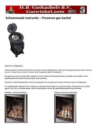
CONVERSION<br />
6<br />
converting to a different type of<br />
gas<br />
■ Check that the values indicated on the<br />
components correspond with the values in<br />
the accompanying table.<br />
■ Close the gas tap.<br />
■ Replace the pressure regulator for natural<br />
gas with the adjusting screw for propane<br />
(or vice versa).<br />
■ Replace the main injection nozzle with the<br />
nozzle from the conversion kit.<br />
■ Replace the pilot light injection nozzle with<br />
the nozzle from the conversion kit.<br />
■ Replace the low-setting restrictor with the<br />
low-setting restrictor from the conversion<br />
kit.<br />
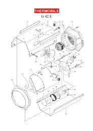
1. Measurement point for burner<br />
pressure<br />
2. Measurement point for supply<br />
pressure<br />
3. Pressure regulator or<br />
adjusting screw<br />
4. Low-setting restrictor<br />
5. Pilot light<br />
6. Mounting bracket<br />
7. Supply pipe<br />
8. Burner pipe<br />
9. Main burner<br />
10. Injection nozzle<br />
11. Taper ring and coupling nut<br />
fig. 7<br />
■ Replace the settings plate with the settings<br />
place from the conversion kit.<br />
■ Adjust the burner pressure as per the table<br />
supplied with the conversion kit. In the<br />
case of appliances without pressure<br />
regulator pay particular attention to<br />
whether, with the appliance turned on full,<br />
the supply pressure corresponds with the<br />
appliance’s rated inlet pressure.<br />
■ Check all connections previously<br />
dismantled for leaks.<br />
1<br />
2<br />
3<br />
9<br />
4<br />
5<br />
10 11<br />
6<br />
7<br />
8<br />
lighting<br />
■ Open the gas tap.<br />
■ Turn control knob B to position and<br />
press it in. Gas will now flow to the pilot<br />
light burner.<br />
fig. 8<br />
1 2 3 4 5 6 7<br />
■ Press ignition button A. A spark will now<br />
jump to the pilot light burner. Keep the<br />
ignition pressed in until the pilot light<br />
ignites, then keep knob B pressed in for<br />
approximately a further 10 seconds.<br />
■ If the pilot light now goes out again, the<br />
preceding action has to be repeated and<br />
ignition button B must be held in for a little<br />
longer.<br />
■ Once the pilot light is lit you can select a<br />
setting between 1 and 7 with thermostat<br />
knob B.<br />
A<br />
B<br />
switching off<br />
■ If you turn the control knob to the position<br />
between and 1, only the pilot light will<br />
burn. This is also the frost-protection<br />
position, i.e. at this setting the main burner<br />
will only be switched on at a very low<br />
ambient temperature to keep the room<br />
frost-free. You should therefore leave the<br />
pilot light on during the heating season.<br />
■ Turn control knob B to position . The<br />
heater is now completely switched off.<br />
USE<br />
7