40010435 PELGRIM GWH NE/EN/FR - Gaswinkel
40010435 PELGRIM GWH NE/EN/FR - Gaswinkel
40010435 PELGRIM GWH NE/EN/FR - Gaswinkel

Create successful ePaper yourself
Turn your PDF publications into a flip-book with our unique Google optimized e-Paper software.
40 010 435<br />
50/00<br />
Handleiding<br />
Manual<br />
Notice d’utilisation<br />
gevelkachel<br />
wall-mounted heater<br />
radiateur gaz modulable<br />
<strong>GWH</strong> 2/3/4/5
TOESTELBESCHRIJVING<br />
toestelbeschrijving<br />
1 bedieningsklep<br />
2 regelblok<br />
fig. 1<br />
40 cm<br />
70 cm<br />
1 2 3 4 5 6 7<br />
1 2<br />
20,7 cm<br />
1 2 3 4 5 6 7<br />
50 cm<br />
20,7 cm<br />
50 cm<br />
voorwoord<br />
Deze gevelkachel is speciaal ontwikkeld om<br />
tegen een buitenmuur te plaatsen. De<br />
afvoergassen worden direct door de muur<br />
naar buiten gevoerd.<br />
De gevelkachel is volledig beveiligd door<br />
middel van een thermo-elektrische<br />
waakvlambeveiliging ter voorkoming van het<br />
onvoorzien uitstromen van gas uit de<br />
hoofdbrander.<br />
60 cm<br />
80 cm<br />
1 2 3 4 5 6 7<br />
20,7 cm<br />
1 2 3 4 5 6 7<br />
50 cm<br />
20,7 cm<br />
50 cm<br />
introductie<br />
Als u deze handleiding doorleest bent u snel<br />
op de hoogte van de mogelijkheden die deze<br />
kachel u biedt. U vindt adviezen over de<br />
veiligheid tijdens het gebruik en informatie<br />
over de installatie, de bediening en het<br />
onderhoud van de kachel.<br />
Bij het samenstellen van deze handleiding is<br />
er van uitgegaan dat de kachel wordt<br />
geplaatst door een erkend gastechnisch<br />
installateur die op de hoogte is van de<br />
nationaal en lokaal geldende voorschriften.<br />
Bewaar dit boekje, zodat een volgende<br />
gebruiker er zijn voordeel mee kan doen.<br />
inhoudsopgave<br />
inleiding 1<br />
veiligheid 2<br />
plaatsing 3<br />
installatie 4 - 5<br />
ombouwen 6<br />
gebruik 7<br />
reiniging 8<br />
storingen 9<br />
afvoeren verpakking en toestel 9<br />
onderdelenlijst I<br />
technische gegevens II - IX<br />
INHOUDSOPGAVE<br />
1
2 VEILIGHEID<br />
veiligheid<br />
■ Deze kachel mag uitsluitend worden<br />
geplaatst en geïnstalleerd door een erkend<br />
installateur.<br />
■ De mantel van deze kachel is een 'werkend<br />
oppervlak', d.w.z. dat deze een hoge<br />
temperatuur kan bereiken. Wees dus<br />
voorzichtig met kinderen; houdt ze uit de<br />
buurt van de kachel of plaats een hekje<br />
rond de kachel.<br />
■ Leg nooit voorwerpen op de brandende<br />
kachel.<br />
■ Gebruik de kachel nooit om er kleren,<br />
handdoeken etc. op te drogen; wanneer<br />
men n.l. de mantel afsluit ontstaan er<br />
binnen de mantel zeer hoge temperaturen.<br />
■ Omdat de opstijgende lucht boven de<br />
kachel een vrij hoge temperatuur heeft<br />
mag er geen vitrage of gordijn vlak boven<br />
de kachel worden gehangen. Plaats de<br />
kachel niet vast onder een brandbare<br />
vensterbank. Houdt minimaal 15 cm aan als<br />
afstand tussen de mantel en gordijnen of<br />
een brandbare vensterbank boven de<br />
mantel.<br />
■ In verband met een goede en veilige<br />
werking van deze gevelkachel is periodiek<br />
onderhoud (minimaal 1 keer per jaar, bijv.<br />
aan het begin van het stookseizoen) door<br />
een erkend persoon aan te bevelen.<br />
■ Mocht de kachel, door welke oorzaak dan<br />
ook, zijn uitgegaan, wacht dan minimaal<br />
5 minuten voordat u het toestel weer<br />
ontsteekt.<br />
■ Gebruik een goedgekeurde aansluitkraan in<br />
de gastoevoer voor het aansluiten van de<br />
kachel.<br />
■ De kachel mag alleen gerepareerd worden<br />
met originele onderdelen.<br />
■ Verbrand stof verspreidt een onaangename<br />
geur en leidt bovendien tot verkleuring van<br />
wanden en plafonds. Deze verkleuring is<br />
echter nooit geheel te voorkomen, maar<br />
wel tot een minimum te beperken door het<br />
vertrek, de mantel en het binnenwerk<br />
stofvrij te houden.<br />
gassoort en gasdruk<br />
Het toestel is afgesteld en verzegeld in de<br />
fabriek, overeenkomstig de op de kenplaat<br />
aangegeven categorie en op de juiste<br />
nominale belasting. De waakvlambrander is<br />
afgesteld op het juiste verbruik. Controleer of<br />
de gegevens op de kenplaat overeenkomen<br />
met de lokale gassoort en de druk. Controleer<br />
of de gegevens op de typeplaat overeenkomen<br />
met de aard van uw installatie (zie technische<br />
gegevens voor controle). De typeplaat vindt u<br />
op de achterplaat.<br />
plaatsing<br />
Deze gevelkachel mag alleen tegen een<br />
buitenmuur geplaatst worden omdat de<br />
verbrandingsproducten direct naar buiten<br />
moeten worden afgevoerd.<br />
Het toestel mag alleen worden geïnstalleerd<br />
door een erkend installateur volgens de<br />
nationaal en lokaal geldende voorschriften.<br />
Plaats de kachel bij voorkeur niet in een hoek<br />
omdat de brander voor periodiek onderhoud<br />
uit het toestel verwijderd moet kunnen<br />
worden.<br />
Plaats het muurrooster aan de buitenzijde niet<br />
te dicht onder een vensterbank (zie ook<br />
"veiligheid").<br />
PLAATSING<br />
3
4 INSTALLATIE<br />
lengte van de in- en uitlaatkoker<br />
Muurdikte: minimaal 70 mm<br />
Lengte inlaatkoker: muurdikte + 10 mm.<br />
Lengte uitlaatkoker: muurdikte + 70 mm,<br />
maximale lengte 600 mm.<br />
installatie van het toestel<br />
Bij dit toestel is een montageplaat<br />
meegeleverd, die dienst doet als aftekenmal<br />
en als montage-eenheid voor de<br />
muurdoorvoer en het binnenwerk. De gaten A,<br />
B en C in fig. 2 zijn voor de<br />
bevestigingsschroeven. De minimumafstand<br />
van de onderkant van deze montageplaat t.o.v.<br />
de vloer moet 20 mm zijn (295 mm van vloer tot<br />
onderkant kokergat).<br />
A B<br />
fig. 2<br />
Het gat voor de muurkoker moet inwendig<br />
rond zijn en een binnendiameter van 153 mm<br />
hebben. Het is aan te bevelen, dit gat te<br />
(laten) boren.<br />
Om inregenen te voorkomen moet dit gat<br />
waterpas zijn en mag het zeker niet aflopen<br />
naar de binnenkant.<br />
C<br />
Indien de kachel wordt geplaatst voor een<br />
brandbare wand moet de diameter van de<br />
muurdoorvoer 180 mm zijn en dient over het<br />
gehele oppervlak achter de montageplaat een<br />
plaat van onbrandbaar materiaal te worden<br />
aangebracht met daarin een gat van 153 mm.<br />
Het verdient aanbeveling, deze plaat op 2 à<br />
3 mm vrij van de wand te monteren.<br />
Houdt bij de bepaling van de plaats waar het<br />
toestel geïnstalleerd moet worden ook<br />
rekening met de voorwaarden, genoemd in het<br />
hoofdstuk 'plaatsing'.<br />
■ Teken de gaten voor de keilbouten en het<br />
muurkokergat af m.b.v. de montageplaat.<br />
Let op dat dit waterpas gebeurt.<br />
■ Boor de gaten.<br />
■ Maak de inlaatkoker (grootste diameter) op<br />
maat.<br />
■ Monteer de keilbouten in de geboorde<br />
gaten in de muur.<br />
■ Bevestig de montageplaat aan de muur.<br />
■ Controleer met een waterpas of de<br />
montageplaat horizontaal hangt en draai de<br />
bevestigingsschroeven vast.<br />
■ Bevestig de inlaatkoker aan het<br />
afvoerrooster. Draai de trekstangen in het<br />
muurrooster. Schuif daarna het rooster op<br />
de inlaatkoker.<br />
■ Steek deze van buiten door het gat in de<br />
muur.<br />
■ Steek nu de trekstangen door de hiervoor<br />
bestemde gaten in de montageplaat (de<br />
uitlaat hoort boven) en zet het geheel met<br />
de bijgeleverde moeren vast.<br />
fig. 3<br />
■ Zorg ervoor dat de draadeinden niet te ver<br />
uitsteken (max. 10 mm inclusief moer).<br />
Zaag de overtollige lengte af.<br />
■ Maak nu de aluminium uitlaatkoker op<br />
lengte (muurdikte + 70 mm).<br />
■ Steek de uitlaatkoker in de daarvoor<br />
bestemde opening van het muurrooster.<br />
fig. 4<br />
■ Pak het binnenwerk en leg de<br />
glasvezelafdichting om de luchtinlaat.<br />
■ Zet het binnenwerk met de onderkant op de<br />
onderste steunen.<br />
■ Schuif het binnenwerk met de<br />
geleidingssteunen om de lippen op de<br />
montageplaat.<br />
fig. 5<br />
■ Steek de afvoer van het binnenwerk om de<br />
afvoerbuis.<br />
■ Schuif het binnenwerk horizontaal naar<br />
achteren tot de pinnen aan de onderzijde<br />
van het binnenwerk in de fixatie van de<br />
horizontale steunen vallen. Zet het<br />
binnenwerk vast door de geleidingssteunen<br />
vast te schroeven aan de bovenzijde.<br />
■ Plaats de mantel verticaal tegen de muur<br />
en de montageplaat, zodat de nokjes in de<br />
sleufgaten vallen. Laat de mantel<br />
rechtstandig naar beneden zakken.<br />
fig. 6<br />
1 2<br />
aansluiting op de gasleiding<br />
■ Vermijd spanningen op de regelkraan bij<br />
het aansluiten. Controleer de<br />
gasaansluiting op gasdichtheid. Controleer<br />
de werking van de kachel en leg deze uit<br />
aan de gebruiker.<br />
INSTALLATIE<br />
5
6 OMBOUW<strong>EN</strong><br />
ombouwen op een andere<br />
gassoort<br />
■ Controleer of de waarden zoals vermeld op<br />
de onderdelen overeenkomen met de<br />
waarden uit de bijgeleverde tabel.<br />
■ Sluit de gaskraan.<br />
■ Vervang de drukregelaar aardgas door de<br />
stelschroef propaan (of andersom).<br />
■ Vervang de hoofdinspuiter door de<br />
inspuiter uit de ombouwset.<br />
■ Vervang de waakvlaminspuiter door de<br />
inspuiter uit de ombouwset.<br />
■ Vervang de kleinstandstuw door de<br />
kleinstandstuw uit de ombouwset.<br />
1. Drukmeetpunt branderdruk<br />
2. Drukmeetpunt voordruk<br />
3. Drukregelaar of stelschroef<br />
4. Kleinstandstuw<br />
5. Waakvlam<br />
6. Bevestigingsbeugel<br />
7. Toevoerleiding<br />
8. Branderleiding<br />
9. Hoofdbrander<br />
10. Inspuiter<br />
11. Kegelring + wartel<br />
fig. 7<br />
■ Vervang het instelplaatje door de<br />
instelplaat uit de ombouwset.<br />
■ Stel de branderdruk in volgens de tabel<br />
zoals wordt bijgeleverd met de ombouwset.<br />
Let bij toestellen zonder drukregelaar<br />
speciaal op of de voordruk van een op<br />
volstand brandend toestel overeenkomt<br />
met de aansluitdruk van het toestel.<br />
■ Controleer alle eerder gedemonteerde<br />
aansluitingen op gasdichtheid.<br />
1<br />
2<br />
3<br />
9<br />
4<br />
5<br />
10 11<br />
6<br />
7<br />
8<br />
aansteken<br />
■ Open de gaskraan.<br />
■ Draai bedieningsknop B naar stand<br />
druk deze in. Er stroomt nu gas naar de<br />
waakvlambrander.<br />
en<br />
fig. 8<br />
1 2 3 4 5 6 7<br />
■ Druk ontstekingsknop A in. Er springt nu<br />
een vonk over naar de waakvlambrander.<br />
Herhaal het indrukken tot de waakvlam<br />
ontstoken is. Houdt knop B nog ca.<br />
10 seconden ingedrukt.<br />
■ Als de waakvlam nu dooft moeten<br />
voorgaande handelingen herhaald worden<br />
en moet de aansteekknop B iets langer<br />
ingedrukt gehouden worden.<br />
■ Nadat de waakvlam is ontstoken kunt u met<br />
thermostaatknop B een stand kiezen tussen<br />
1 en 7.<br />
A<br />
B<br />
uitschakelen<br />
■ Als u de bedieningsknop op de stand<br />
tussen en 1 draait brandt alleen de<br />
waakvlam. Dit is tevens de vorstbeveiliging,<br />
hetgeen wil zeggen dat de hoofdbrander<br />
pas ingeschakeld wordt bij een zeer lage<br />
omgevingstemperatuur om de ruimte<br />
vorstvrij te houden. Laat daarom de<br />
waakvlam tijdens het stookseizoen<br />
branden.<br />
■ Draai de bedieningsknop B naar stand<br />
De kachel is nu helemaal uitgeschakeld.<br />
.<br />
GEBRUIK<br />
7
8 REINIGING<br />
reiniging en onderhoud<br />
De kachel dient jaarlijks te worden gereinigd<br />
en gecontroleerd door een erkend installateur.<br />
Controle op:<br />
- dichtheid van gascircuit;<br />
- de juiste werking van de regelkraan, het<br />
thermokoppelcircuit en het ontsteken van de<br />
brander.<br />
Reiniging van:<br />
- het waakvlamsysteem;<br />
- de brander;<br />
- de verbrandingsruimte;<br />
- de rookgasafvoer.<br />
reiniging van de brander<br />
Wanneer de kachel is afgekoeld, kan de<br />
brander gereinigd worden.<br />
Verbrand stof verspreid een onaangename<br />
geur en leidt bovendien tot verkleuring van<br />
wanden en plafonds. Deze verkleuring is<br />
echter nooit geheel te voorkomen, maar wel<br />
tot een minimum te beperken door het vertrek,<br />
de mantel en het binnenwerk stofvrij te<br />
houden.<br />
Verkleuring van de mantel is te voorkomen<br />
door deze regelmatig te reinigen met water of<br />
met zeep. Na het schoonmaken goed<br />
nabehandelen met schoon water en droog<br />
wrijven. Gebruik nooit agressieve of<br />
schurende schoonmaakmiddelen voor de<br />
mantel.<br />
storingen<br />
Niet aangaan of uitgaan van de kachel.<br />
Oorzaken:<br />
- Lucht in de toevoerleiding (na stilstand van<br />
het toestel).<br />
> Ontluchten.<br />
- Onvoldoende gasdruk.<br />
> Controleer of de gastoevoerleiding is<br />
vervuild of dat de aansluitkraan niet open<br />
staat.<br />
- Waakvlam is vervuild.<br />
> Maak de brander voorzichtig schoon met<br />
een stofzuiger.<br />
- De aansluiting van het thermokoppel maakt<br />
geen goed contact.<br />
> Controleer het thermo-elektrisch circuit.<br />
afvoeren verpakking en toestel<br />
De verpakking van het toestel is recyclebaar.<br />
Gebruikt kunnen zijn:<br />
- karton;<br />
- CFK-vrij schuim (zacht);<br />
- hout;<br />
- plastic;<br />
- papier.<br />
Deze materialen moeten op verantwoorde<br />
wijze en conform de overheidsbepalingen<br />
worden afgevoerd.<br />
De overheid kan u ook informatie verschaffen<br />
over het op verantwoorde wijze afvoeren van<br />
afgedankte apparaten.<br />
STORING<strong>EN</strong><br />
9
DESCRIPTION<br />
description<br />
1 control valve<br />
2 control block<br />
fig. 1<br />
40 cm<br />
70 cm<br />
1 2 3 4 5 6 7<br />
1 2<br />
20,7 cm<br />
1 2 3 4 5 6 7<br />
50 cm<br />
20,7 cm<br />
50 cm<br />
foreword<br />
This wall-mounted heater has been specially<br />
developed for mounting on an external wall.<br />
The flue gases are vented directly to the<br />
outside through the external wall.<br />
The wall-mounted heater is fully protected by<br />
means of a thermo-electric pilot-light<br />
safeguard to prevent accidental outflow of<br />
gas from the main burner.<br />
60 cm<br />
80 cm<br />
1 2 3 4 5 6 7<br />
20,7 cm<br />
1 2 3 4 5 6 7<br />
50 cm<br />
20,7 cm<br />
50 cm<br />
introduction<br />
If you read this manual, you will soon become<br />
acquainted with the possibilities this heater<br />
offers. The manual contains advice on safe<br />
use and information on installation, operation<br />
and maintenance of the heater.<br />
This manual has been compiled on the<br />
assumption that the heater will be installed by<br />
an authorised gas installer who is familiar<br />
with national and local regulations.<br />
Keep this book in a safe place, so that future<br />
users can benefit from this information.<br />
.<br />
table of contents<br />
introduction 1<br />
safety 2<br />
positioning 3<br />
installation 4 - 5<br />
conversion 6<br />
use 7<br />
cleaning 8<br />
faults 9<br />
disposal of packaging and appliance 9<br />
parts list I<br />
technical information II - IX<br />
TABLE OF CONT<strong>EN</strong>TS<br />
1
2 SAFETY<br />
safety<br />
■ This heater may only be positioned and<br />
installed by an authorised installer.<br />
■ The housing of this heater can reach high<br />
temperatures. Be careful therefore with<br />
children: keep them away from the heater<br />
or place a guard around the heater.<br />
■ Never place objects on the heater when it<br />
is working.<br />
■ Never use the heater to dry clothes,<br />
towels, etc.; if the housing is covered, very<br />
high temperatures will develop inside the<br />
housing.<br />
■ Since the rising air above the heater is at a<br />
fairly high temperature, curtains or ‘nets’<br />
must not be positioned directly above the<br />
heater. Do not install the heater below a<br />
window ledge made of combustible<br />
material. The minimum distance between<br />
the housing and curtains or a combustible<br />
window ledge above the housing should be<br />
15 cm.<br />
■ Periodic maintenance (at least once a year,<br />
for example at the start of the heating<br />
season) by an authorised person is<br />
advisable in order to ensure effective, safe<br />
operation of this heater.<br />
■ If, for whatever reason, the heater has<br />
gone out, wait for at least 5 minutes before<br />
re-lighting the appliance.<br />
■ Use an approved gas tap to connect the<br />
heater to the gas main.<br />
■ The heater may only be repaired using<br />
original parts.<br />
■ Burnt dust causes an unpleasant smell and<br />
also results in discoloration of walls and<br />
ceilings. Although such discoloration can<br />
never be entirely prevented, it can be<br />
minimised by keeping the room, the<br />
housing and the interior free from dust.<br />
gas type and pressure<br />
The hearth is set to the nominal load, in<br />
accordance with the category stated on the<br />
identification plate, and sealed at the factory.<br />
The pilot light is set to the correct flow. See the<br />
technical data for this information. Check that<br />
the data on the identification plate corresponds<br />
to the local gas type and pressure. Check that<br />
the data on the identification plate correspond<br />
to the type and voltage of the current in your<br />
building. The identification plate is located on<br />
the rear panel of the heater.<br />
positioning<br />
This wall-mounted heater may only be<br />
positioned against an external wall as the<br />
products of combustion have to be vented<br />
direct to the outside air.<br />
The unit may only be installed by an<br />
authorised installer and in accordance with<br />
national and local regulations.<br />
The heater should preferably not be<br />
positioned in a corner as the burner has to be<br />
capable of being removed from the heater for<br />
periodic maintenance.<br />
Do not install the external wall grille too close<br />
to a windowsill (see also ‘safety’).<br />
POSITIONING<br />
3
4 INSTALLATION<br />
length of inlet and outlet pipe<br />
Wall thickness: minimum 70 mm<br />
Length of inlet pipe: as wall thickness.<br />
Length of outlet pipe: wall thickness + 70 mm,<br />
maximum length 600 mm.<br />
installing the appliance<br />
The mounting plate supplied with this<br />
appliance will serve as a template and as an<br />
assembly unit for the wall vent and the<br />
internal mechanism. Holes A, B and C in fig. 2<br />
are for the mounting screws. The minimum<br />
distance from the bottom of this mounting<br />
plate to the floor must be 20 mm (295 mm from<br />
the floor to the bottom of the vent-pipe hole).<br />
fig. 2<br />
A B<br />
C<br />
The hole for the wall vent-pipe must be round<br />
and have an internal diameter of 153 mm. It is<br />
advisable to drill this hole or arrange for it to<br />
be drilled.<br />
To avoid ingress of rain this hole must be level<br />
and must certainly not slope downwards<br />
towards the inside.<br />
If the heater is installed against a wall made<br />
from combustible material, the diameter of the<br />
wall opening must be 180 mm and a sheet of<br />
incombustible material, containing a 153 mm<br />
diameter hole, must be installed to cover the<br />
entire surface behind the mounting plate. It is<br />
advisable to mount this sheet 2 to 3 mm clear<br />
of the wall.<br />
When determining the place at which the<br />
appliance is to be installed, account must also<br />
be taken of the conditions indicated in the<br />
section on ‘positioning’.<br />
■ Draw the holes for the key bolts and the<br />
opening for the wall vent pipe using the<br />
mounting plate. Make sure that the plate is<br />
level.<br />
■ Drill the holes.<br />
■ Cut the inlet pipe (largest diameter) to size.<br />
■ Place the key bolts in the holes drilled in<br />
the wall.<br />
■ Secure the mounting plate to the wall.<br />
■ Using a spirit level check that the mounting<br />
plate is horizontal and tighten the mounting<br />
screws.<br />
■ Secure the inlet pipe to the flue grille.<br />
Screw the tensioning members into the<br />
wall grille. Then slide the grille on to the<br />
inlet pipe.<br />
■ Push the pipe through the hole in the wall<br />
from the outside.<br />
■ Now insert the tensioning members through<br />
the holes provided for this purpose in the<br />
mounting plate (the outlet should be at the<br />
top) and secure with the nuts supplied.<br />
fig. 3<br />
■ Make sure that the stud bolts do not<br />
protrude too far (maximum 10 mm including<br />
nut). Saw off the surplus length.<br />
■ Now cut the aluminium outlet pipe to size<br />
(wall thickness + 70 mm).<br />
■ Insert the outlet pipe into the opening<br />
provided for that purpose in the wall grille.<br />
fig. 4<br />
■ Take the internal mechanism and place the<br />
fibreglass packing around the air inlet.<br />
■ Place the internal mechanism with the<br />
base resting on the lower supports.<br />
■ Slide the internal mechanism with the<br />
support guides around the lips on the<br />
mounting plate.<br />
fig. 5<br />
■ Slide the outlet from the internal<br />
mechanism on to the flue pipe.<br />
■ Slide the internal mechanism horizontally<br />
backwards until the pins on the base of the<br />
internal mechanism engage with the<br />
horizontal supports. Secure the internal<br />
mechanism by screwing the support guides<br />
tight at the top.<br />
■ Place the casing vertically against the wall<br />
and the mounting plate, so that the<br />
projections fit into the slotted holes. Lower<br />
the casing vertically.<br />
fig. 6<br />
1 2<br />
connection to the gas supply<br />
■ Avoid straining the regulator tap when<br />
connecting. Check gas connections for<br />
leaks. Check the operation of the heater<br />
and explain it to the user.<br />
INSTALLATION<br />
5
CONVERSION<br />
6<br />
converting to a different type of<br />
gas<br />
■ Check that the values indicated on the<br />
components correspond with the values in<br />
the accompanying table.<br />
■ Close the gas tap.<br />
■ Replace the pressure regulator for natural<br />
gas with the adjusting screw for propane<br />
(or vice versa).<br />
■ Replace the main injection nozzle with the<br />
nozzle from the conversion kit.<br />
■ Replace the pilot light injection nozzle with<br />
the nozzle from the conversion kit.<br />
■ Replace the low-setting restrictor with the<br />
low-setting restrictor from the conversion<br />
kit.<br />
1. Measurement point for burner<br />
pressure<br />
2. Measurement point for supply<br />
pressure<br />
3. Pressure regulator or<br />
adjusting screw<br />
4. Low-setting restrictor<br />
5. Pilot light<br />
6. Mounting bracket<br />
7. Supply pipe<br />
8. Burner pipe<br />
9. Main burner<br />
10. Injection nozzle<br />
11. Taper ring and coupling nut<br />
fig. 7<br />
■ Replace the settings plate with the settings<br />
place from the conversion kit.<br />
■ Adjust the burner pressure as per the table<br />
supplied with the conversion kit. In the<br />
case of appliances without pressure<br />
regulator pay particular attention to<br />
whether, with the appliance turned on full,<br />
the supply pressure corresponds with the<br />
appliance’s rated inlet pressure.<br />
■ Check all connections previously<br />
dismantled for leaks.<br />
1<br />
2<br />
3<br />
9<br />
4<br />
5<br />
10 11<br />
6<br />
7<br />
8<br />
lighting<br />
■ Open the gas tap.<br />
■ Turn control knob B to position and<br />
press it in. Gas will now flow to the pilot<br />
light burner.<br />
fig. 8<br />
1 2 3 4 5 6 7<br />
■ Press ignition button A. A spark will now<br />
jump to the pilot light burner. Keep the<br />
ignition pressed in until the pilot light<br />
ignites, then keep knob B pressed in for<br />
approximately a further 10 seconds.<br />
■ If the pilot light now goes out again, the<br />
preceding action has to be repeated and<br />
ignition button B must be held in for a little<br />
longer.<br />
■ Once the pilot light is lit you can select a<br />
setting between 1 and 7 with thermostat<br />
knob B.<br />
A<br />
B<br />
switching off<br />
■ If you turn the control knob to the position<br />
between and 1, only the pilot light will<br />
burn. This is also the frost-protection<br />
position, i.e. at this setting the main burner<br />
will only be switched on at a very low<br />
ambient temperature to keep the room<br />
frost-free. You should therefore leave the<br />
pilot light on during the heating season.<br />
■ Turn control knob B to position . The<br />
heater is now completely switched off.<br />
USE<br />
7
8 CLEANING<br />
maintenance and cleaning<br />
The heater should be cleaned and checked<br />
annually by an authorised installer.<br />
Check that:<br />
-the gas supply is airtight;<br />
-the regulator and the thermocouple circuit<br />
function properly and that the burner ignites<br />
properly.<br />
Clean (if necessary):<br />
-the pilot system;<br />
-the burner;<br />
-the combustion chamber;<br />
-the flue gas exhaust.<br />
cleaning the burner<br />
Once the heater has cooled down sufficiently,<br />
the burner can be cleaned.<br />
Burnt dust gives off an unpleasant smell and<br />
also results in discoloration of walls and<br />
ceilings. Although such discoloration can<br />
never be entirely avoided, it can be restricted<br />
to a minimum by keeping the room, the<br />
housing and the internal mechanism free of<br />
dust.<br />
Discoloration of the housing can be prevented<br />
by cleaning it regularly with soap and water.<br />
After cleaning, rinse thoroughly with clean<br />
water and rub dry. Never use aggressive or<br />
abrasive cleaning agents for the housing.<br />
faults<br />
Heater fails to light or extinguish.<br />
Causes:<br />
- Air in supply pipe (after appliance has been<br />
out of operation).<br />
> Vent.<br />
- Insufficient gas pressure.<br />
> Check that the gas tap is open and check<br />
the gas line to see if it is dirty.<br />
- The pilot light is dirty.<br />
> Clean the burner carefully with a vacuum<br />
cleaner.<br />
- The thermocouple contact does not engage<br />
properly.<br />
> Check the thermocouple circuit.<br />
disposing of the packaging and<br />
appliancel<br />
The appliance packaging is recyclable. The<br />
packaging could include the following<br />
materials:<br />
- card board;<br />
- CFC-free foam (soft);<br />
- wood<br />
- plastic;<br />
- paper.<br />
These materials should be disposed<br />
responsibly and in conformity with government<br />
regulations.<br />
Information on how to responsibly dispose of<br />
discarded appliances can be obtained from the<br />
local authorities.<br />
9 FAULTS
DESCRIPTION<br />
description de l’apparel<br />
1 soupape de commande<br />
2 bloc de réglage<br />
fig. 1<br />
40 cm<br />
70 cm<br />
1 2 3 4 5 6 7<br />
1 2<br />
20,7 cm<br />
1 2 3 4 5 6 7<br />
50 cm<br />
20,7 cm<br />
50 cm<br />
avant-propos<br />
Ce radiateur à gaz mural a été spécialement<br />
conçu pour être placé contre un mur extérieur.<br />
Les gaz d'échappement vont directement vers<br />
l'extérieur en traversant le mur.<br />
Le radiateur en question comprend également<br />
une sécurité thermoélectrique pour la flamme.<br />
L'afflux imprévu de gaz à partir du brûleur<br />
principal est ainsi évité.<br />
60 cm<br />
80 cm<br />
1 2 3 4 5 6 7<br />
20,7 cm<br />
1 2 3 4 5 6 7<br />
50 cm<br />
20,7 cm<br />
50 cm<br />
introduction<br />
La lecture de ce mode d'emploi vous<br />
permettra de recevoir une information rapide<br />
sur les possibilités que ce radiateur peut vous<br />
offrir. Vous y trouverez des conseils de<br />
sécurité se rapportant à l'utilisation et des<br />
informations visant l'installation, la commande<br />
et l'entretien de ce radiateur.<br />
La rédaction de ce mode d'emploi repose sur<br />
l'idée que ce radiateur sera mis en place par<br />
un installateur agréé dans la technique du gaz<br />
et ayant une bonne connaissance des<br />
consignes qui sont en vigueur sur les plans<br />
local et national.<br />
Prenez soin de garder ce livret, afin qu’un autre<br />
utilisateur puisse en profiter.<br />
contenu<br />
introduction 1<br />
securité 2<br />
positioning 3<br />
installation 4 - 5<br />
transformer 6<br />
usage 7<br />
entretien 8<br />
panne 9<br />
élimination de l’emballage et de l’appareil 9<br />
supplement I<br />
fiche technique II - IX<br />
CONT<strong>EN</strong>U<br />
1
2 SECURITE<br />
Securité<br />
■ Seul un installateur agréé est autorisé à<br />
faire le placement et l'installation de cet<br />
appareil.<br />
■ Le manteau de ce radiateur est une<br />
"surface en fonction", ce qui veut dire que<br />
celle-ci peut atteindre une température<br />
élevée. Soyez donc prudent en cas<br />
d'enfants : tenez-les à distance de ce<br />
radiateur ou placez une grille autour de<br />
l'appareil.<br />
■ Ne posez jamais d'objets sur l'appareil<br />
lorsqu'il fonctionne.<br />
■ N'utilisez jamais l'appareil pour sécher des<br />
vêtements, des serviettes, etc. : en cas de<br />
fermeture du manteau, les températures<br />
risquent là de s'élever très fortement.<br />
■ Vu que l'air qui s'élève au-dessus de<br />
l'appareil est d'une température assez<br />
élevée, il est interdit d'accrocher un<br />
vitrage ou des rideaux à proximité du<br />
radiateur. Ne placez pas le radiateur sous<br />
un rebord de fenêtre inflammable.<br />
Respectez une distance minimale de 15 cm<br />
entre le manteau et les rideaux ou un<br />
rebord de fenêtre inflammable situés audessus<br />
du manteau.<br />
■ Pour assurer le fonctionnement sûr et<br />
correct de ce radiateur, il est recommandé<br />
de faire appel à un spécialiste pour<br />
exécuter un entretien périodique (au<br />
minimum 1 fois par an, par exemple, au<br />
début de la saison froide).<br />
■ En cas d'un arrêt inattendu de l'appareil,<br />
attendez au moins 5 minutes avant de le<br />
remettre en route.<br />
■ Utilisez un robinet à gaz agréé dans<br />
l'arrivée du gaz pour le branchement de<br />
l'appareil.<br />
■ En cas de réparations, veuillez n'utiliser<br />
que les pièces d'origine du radiateur.<br />
■ La poussière brûlée dégage une odeur<br />
désagréable et conduit, en outre, à une<br />
coloration des murs et plafonds. S'il est<br />
toutefois impossible d'éviter cette<br />
coloration, il est possible de la limiter à un<br />
minimum en évitant à la poussière de<br />
s'installer dans la pièce, le manteau et<br />
l'aménagement intérieur.<br />
type de gaz et pression du gaz<br />
L’appareil est mis au point et cacheté à l’usine,<br />
sur la charge<br />
nominale appropriée, conformément à la<br />
catégorie I2L indiquée sur l’immatriculation. Le<br />
brûleur de la veilleuse est réglé pour une<br />
utilisation appropriée. Voir Caractéristiques<br />
techniques pour le contrôle. Vérifiez que les<br />
données de l’immatriculation correspondent au<br />
gaz local et à la pression du gaz locale. La<br />
plaque du modèle se trouve sur la plaque de<br />
derrière.<br />
placement<br />
Ce radiateur ne doit être placé que contre un<br />
mur extérieur vu que les produits de la<br />
combustion sont directement conduits vers<br />
l'extérieur.<br />
Seul un installateur agréé est autorisé à<br />
installer l'appareil en tenant compte des<br />
consignes qui sont en vigueur sur les plans<br />
local et national.<br />
Ne placez pas, de préférence, l'appareil dans<br />
un angle vu qu'il doit être possible d'enlever<br />
le brûleur pour lui faire subir un entretien<br />
périodique.<br />
Placez la grille murale à l'extérieur, à une<br />
certaine distance du rebord de fenêtre (voir<br />
aussi "sécurité").<br />
PLACEM<strong>EN</strong>T<br />
3
4 INSTALLATION<br />
longueur du tuyau d'admission et<br />
d'échappement<br />
Épaisseur mur: min. 70 mm<br />
Longueur tuyau d'admission : égale à<br />
l'épaisseur du mur.<br />
Longueur tuyau d'échappement : épaisseur<br />
mur + 70 mm, longueur max. 600 mm.<br />
installation de l'appareil<br />
Une plaque de montage a été fournie avec cet<br />
appareil. Elle sert de gabarit de traçage et<br />
d'unité de montage pour le conduit<br />
d'évacuation mural et l'aménagement<br />
intérieur. Les trous A, B et C à la fig. 2 sont<br />
destinés aux vis de fixation. Les distances<br />
minimales de la partie inférieure de cette<br />
plaque de montage par rapport au sol doivent<br />
être de 20 mm (295 mm du sol jusqu'au trou<br />
de conduit inférieur).<br />
A B<br />
C<br />
fig. 2<br />
Le trou pour le conduit mural doit être rond à<br />
l'intérieur et avoir un diamètre interne de 153mm.<br />
Il est recommandé de (faire) percer ce trou.<br />
Pour éviter à la pluie de faire son entrée, ce<br />
trou doit être horizontal et ne doit surtout pas<br />
suivre une pente vers l'intérieur.<br />
Au cas où le radiateur serait placé devant une<br />
paroi pouvant s'enflammer, le diamètre du<br />
conduit d'évacuation mural doit être de 180<br />
mm et une plaque en matériel ininflammable<br />
doit être placée. Elle doit avoir aussi un trou<br />
de 153 mm. Il est recommandé d'installer cette<br />
paroi à 2 ou 3 mm du mur.<br />
En déterminant l'endroit où vous souhaitez<br />
installer l'appareil, tenez également compte<br />
des conditions nommées dans le chapitre<br />
"placement".<br />
■ Dessinez les trous pour les boulons à<br />
cheville et le trou pour le conduit mural en<br />
utilisant la plaque de montage. Veillez à<br />
une mise de niveau en ce qui concerne<br />
cette opération.<br />
■ Percez les trous.<br />
■ Veillez à ce que le conduit d'admission soit<br />
sur mesure (diamètre le plus grand).<br />
■ Insérez les boulons à cheville dans les<br />
trous qui ont été faits dans le mur.<br />
■ Fixez la plaque de montage au mur.<br />
■ Utilisez un niveau pour contrôler la position<br />
horizontale de la plaque de montage.<br />
Vissez ensuite les vis de fixation.<br />
■ Fixez le conduit d'admission à la grille<br />
d'évacuation. Vissez les tirants dans la<br />
grille murale. Glissez ensuite la grille sur le<br />
conduit d'admission.<br />
■ Introduisez celle-ci de l'extérieur en la faisant<br />
passer par le trou qui a été fait dans le mur.<br />
■ Faites passer maintenant les tirants à<br />
travers les trous destinés à cet effet dans<br />
la plaque de montage (tuyau<br />
d'échappement doit se trouver sur le<br />
dessus) et fixez l'ensemble en utilisant les<br />
écrous fournis.<br />
fig. 3<br />
■ Veillez à ce que les embouts filetés ne<br />
dépassent pas trop (max. 10 mm écrou<br />
compris). Sciez la longueur superflue.<br />
■ Occupez-vous maintenant de la longueur<br />
du conduit d'évacuation en aluminium<br />
(épaisseur du mur + 70 mm).<br />
■ Introduisez le conduit d'évacuation dans le<br />
trou de la grille murale, destiné à cet effet.<br />
fig. 4<br />
■ Prenez l'aménagement intérieur. Colmatez<br />
la bouche d'entrée d'air en l'entourant de<br />
fibre de verre.<br />
■ Placez l'aménagement intérieur en mettant<br />
la partie inférieure sur les supports<br />
inférieurs.<br />
■ Glissez l'aménagement intérieur avec les<br />
supports de guidage. Le tout doit entourer<br />
les rebords qui se trouvent sur la plaque<br />
de montage.<br />
fig. 5<br />
■ Introduisez le tuyau d'évacuation de<br />
l'aménagement intérieur de telle manière<br />
qu'il entoure le tube d'évacuation.<br />
■ Glissez vers l'arrière et horizontalement<br />
l'aménagement intérieur jusqu'à ce que les<br />
chevilles qui se trouvent dans la partie<br />
inférieure de l'aménagement intérieur<br />
s'emboîtent dans la fixation des supports<br />
horizontaux. Fixez l'aménagement intérieur<br />
en vissant en haut les supports de conduite.<br />
■ Placez l'enveloppe verticalement contre le<br />
mur et la plaque de montage pour que les<br />
cames tombent dans les fentes. Faites<br />
glisser verticalement et doucement<br />
l'enveloppe vers le bas.<br />
fig. 6<br />
1 2<br />
INSTALLATION<br />
5
TRANSFORMER<br />
6<br />
raccord à la conduite de gaz<br />
■ Evitez toute tension sur le robinet de<br />
réglage en effectuant le raccord. Contrôlez<br />
le raccord au gaz (étanchéité). Contrôlez le<br />
fonctionnement de l'appareil et expliquez<br />
celui-ci à l'utilisateur.<br />
transformer en une autre sorte de gaz<br />
■ Contrôlez si les valeurs mentionnées sur<br />
les pièces correspondent aux valeurs qui<br />
se trouvent sur le tableau fourni.<br />
■ Fermez le robinet du gaz.<br />
■ Remplacez le régulateur de pression pour<br />
le gaz naturel par la vis de réglage propane<br />
(ou inversement).<br />
■ Remplacez l'injecteur principal par<br />
l'injecteur du jeu de conversion.<br />
1. Section de contrôle de la pression<br />
pour la pression du brûleur<br />
2. Section de contrôle de la pression<br />
pour la pré-pression<br />
3. Régulateur de pression ou vis de<br />
réglage<br />
4. Barre position petit feu<br />
5. Veilleuse<br />
6. Etrier de fixation<br />
7. Conduite d'admission<br />
8. Conduite brûleur<br />
9. Brûleur principal<br />
10. Injecteur<br />
11. Bague conique + émerillon<br />
fig. 7<br />
■ Remplacez l'injecteur pour la veilleuse par<br />
l'injecteur du jeu de conversion.<br />
■ Remplacez la butée de position "petit feu"<br />
par celle qui se trouve dans le jeu de<br />
conversion.<br />
■ Remplacez la plaque de réglage par celle<br />
qui se trouve dans le jeu de conversion.<br />
■ Réglez la pression du brûleur selon le<br />
tableau fourni avec le jeu de conversion.<br />
Veuillez bien contrôler en cas d'appareils<br />
sans régulateur de pression si la prépression<br />
d'un appareil en position élevée<br />
correspond à la pression de branchement<br />
de l'appareil.<br />
■ En rapport avec l'étanchéité, contrôlez<br />
tous les raccords qui ont été démontés<br />
auparavant.<br />
1<br />
2<br />
3<br />
9<br />
4<br />
5<br />
10 11<br />
6<br />
7<br />
8<br />
allumage<br />
■ Ouvrez le robinet du gaz.<br />
■ Tournez le bouton de commande B pour<br />
qu'il se retrouve sur la position .<br />
Enfoncez ensuite celui-ci. Le gaz va<br />
maintenant arriver vers le brûleur de la<br />
veilleuse.<br />
fig. 8<br />
1 2 3 4 5 6 7<br />
■ Appuyez sur le bouton d'allumage A. Une<br />
étincelle va alors se produire qui va se<br />
diriger vers le brûleur de la veilleuse.<br />
Répétez cette opération jusqu'à ce que la<br />
veilleuse soit allumée. Maintenez environ<br />
10 secondes la pression sur le bouton B.<br />
■ Si la veilleuse s'éteint, répétez les<br />
opérations précédentes. Maintenez un peu<br />
plus longtemps la pression sur le bouton<br />
d'allumage B.<br />
■ Après avoir allumé la veilleuse, vous<br />
pouvez choisir en vous aidant du bouton du<br />
thermostat B une position entre 1 et 7.<br />
A<br />
B<br />
mise hors service<br />
■ Si vous tournez le bouton de commande sur<br />
la position entre et 1, seule la veilleuse<br />
fonctionnera. Ceci sert également de<br />
sécurité contre le gel, ce qui veut dire que<br />
le brûleur principal ne s'enclenche que si<br />
la température ambiante est très basse,<br />
ceci pour maintenir la pièce à l'abri du gel.<br />
Pour cette raison, enclenchez la veilleuse<br />
pendant la saison froide.<br />
■ Tournez le bouton de commande B pour<br />
qu'il se trouve sur la position .<br />
L'appareil est maintenant hors service.<br />
USAGE<br />
7
8 <strong>EN</strong>TRETI<strong>EN</strong><br />
entretien et nettoyage<br />
L'appareil doit être nettoyé et contrôlé<br />
annuellement par un installateur agrée.<br />
Contrôle :<br />
- de l’étanchéité du circuit d’alimentation du<br />
gaz ;<br />
- du fonctionnement du robinet de réglage, du<br />
circuit thermocouple et de l’allumage du<br />
brûleur.<br />
Nettoyage (au besoin) :<br />
- du système veilleuse ;<br />
- du brûleur ;<br />
- de l‘espace de combustion ;<br />
- gaz de fumée.<br />
nettoyage du brûleur<br />
Lorsque le poêle est suffisamment refroidi, il<br />
est possible de nettoyer le brûleur.<br />
Si la poussière brûlée dégage une odeur<br />
désagréable, elle conduit, en outre, à la<br />
coloration des murs et des plafonds.<br />
Toutefois, s'il est impossible d'éviter<br />
totalement cette coloration, il est possible de<br />
la limiter à un minimum en éliminant la<br />
poussière qui se trouve dans la pièce, le<br />
manteau et l'aménagement intérieur.<br />
La coloration du manteau peut être évitée en<br />
le nettoyant régulièrement à l'eau ou avec du<br />
savon. Après avoir nettoyé, rincez à l'eau<br />
propre et séchez avec un torchon sec.<br />
N'utilisez jamais de produits d'entretien<br />
agressifs ou abrasifs pour le manteau.<br />
panne<br />
L'appareil ne s'enclenche pas / ne s'arrête pas.<br />
Causes:<br />
- Présence d'air dans la conduite d'amenée<br />
(après arrêt de l'appareil).<br />
> Purger.<br />
- Pression de gaz insuffisante.<br />
> Vérifier : le conduit de gaz est-il sale? Le<br />
robinet est-il fermé?<br />
- Souillure dans la veilleuse.<br />
> Nettoyer délicatement le brûleur à l’aide de<br />
l’aspirateur.<br />
- Mauvais contact de la connection du<br />
thermocouple.<br />
> Vérifier le circuit du thermocouple.<br />
élimination de l’emballage et de<br />
l’appareil<br />
L’emballage de l’appareil est recyclable. Il<br />
contient :<br />
- carton ;<br />
- du polystyrène exempt de CFC (mousse douce) ;<br />
- du bois ;<br />
- du plastic ;<br />
- du papier.<br />
Eliminer ces matériaux de façon adéquate et<br />
conformément à la réglementation en vigueur<br />
dans votre commune.<br />
L’administration communale vous informera<br />
des moyens adéquats de vous débarrasser de<br />
vos anciens appareils ménagers.<br />
9 STORING<strong>EN</strong>/VERPAKKING
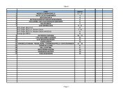
onderdelenlijst / parts list / supplement<br />
set kijkglas / sight glasses set / jeu vitre 20900081<br />
waakvlam set / pilot unit set / jeu veilleuse 20900082<br />
Eurosit 630 compleet / Eurosit 630 complete / Eurosit 630 complet 20900083<br />
Uitlaat set / exhaust set / jeu échappement 20900084<br />
brander <strong>GWH</strong> 2 / burner <strong>GWH</strong> 3 / brûleur <strong>GWH</strong> 2 20900085<br />
set LPG NL <strong>GWH</strong> 2 / set LPG NL <strong>GWH</strong> 2 / jeu GPL NL <strong>GWH</strong> 2 20900086<br />
set LPG eur <strong>GWH</strong> 2 / set LPG eur <strong>GWH</strong> 2 / jeu GPL eur <strong>GWH</strong> 2 20900087<br />
set aardgas NL <strong>GWH</strong> 2 / set NG NL <strong>GWH</strong> 2 / jeu gaz naturel NL <strong>GWH</strong> 2 20900088<br />
set aardgas eur <strong>GWH</strong> 2 / set NG eur <strong>GWH</strong> 2 / jeu gaz naturel eur <strong>GWH</strong> 2 20900089<br />
brander <strong>GWH</strong> 3 / burner <strong>GWH</strong> 3 / brûleur <strong>GWH</strong> 3 20900090<br />
set LPG NL <strong>GWH</strong> 3 / set LPG NL <strong>GWH</strong> 3 / jeu GPL NL <strong>GWH</strong> 3 20900091<br />
set LPG eur <strong>GWH</strong> 3 / set LPG eur <strong>GWH</strong> 3 / jeu GPL eur <strong>GWH</strong> 3 20900092<br />
set aardgas NL <strong>GWH</strong> 3 / set NG NL <strong>GWH</strong> 3 / jeu gaz naturel NL <strong>GWH</strong> 3 20900093<br />
set aardgas eur <strong>GWH</strong> 3 / set NG eur <strong>GWH</strong> 3 / jeu gaz naturel eur <strong>GWH</strong> 3 20900094<br />
brander <strong>GWH</strong> 4 / burner <strong>GWH</strong> 34/ brûleur <strong>GWH</strong> 4 20900095<br />
set LPG NL <strong>GWH</strong> 4 / set LPG NL <strong>GWH</strong> 4 / jeu GPL NL <strong>GWH</strong> 4 20900096<br />
set LPG eur <strong>GWH</strong> 4 / set LPG eur <strong>GWH</strong> 4 / jeu GPL eur <strong>GWH</strong> 4 20900097<br />
set aardgas NL <strong>GWH</strong> 4 / set NG NL <strong>GWH</strong> 4 / jeu gaz naturel NL <strong>GWH</strong> 4 20900098<br />
set aardgas eur <strong>GWH</strong> 4 / set NG eur <strong>GWH</strong> 4 / jeu gaz naturel eur <strong>GWH</strong> 4 20900099<br />
brander <strong>GWH</strong> 5 / burner <strong>GWH</strong> 5 / brûleur <strong>GWH</strong> 5 20900100<br />
set LPG NL <strong>GWH</strong> 5 / set LPG NL <strong>GWH</strong> 5 / jeu GPL NL <strong>GWH</strong> 5 20900101<br />
set LPG eur <strong>GWH</strong> 5 / set LPG eur <strong>GWH</strong> 5 / jeu GPL eur <strong>GWH</strong> 5 20900102<br />
set aardgas NL <strong>GWH</strong> 5 / set NG NL <strong>GWH</strong> 5 / jeu gaz naturel NL <strong>GWH</strong> 5 20900103<br />
set aardgas eur <strong>GWH</strong> 5 / set NG eur <strong>GWH</strong> 5 / jeu gaz naturel eur <strong>GWH</strong> 5 20900104<br />
I
I<br />
Technische gegevens / technical data / fiche technique <strong>GWH</strong> 2<br />
Land / country/pays<br />
NL BE/<strong>FR</strong> DE DE/LU AT/ES/GB/ HU NL/HU NL BE/IT/PT/ES/<strong>FR</strong>/GB BE/ES/<strong>FR</strong>/ AT/DE<br />
IT/PT GB/IT/PT<br />
Soort gas en toevoerdruk/gastype-supply<br />
pressure/type gaz pression d'alimentation<br />
G25-25 G20-20 G20-20 G20-20 G20-20 G20-25 G31-30 G30-29 G30-29 G31-37 G30-50<br />
Cat.<br />
I2L I2E+ I2ELL I2E I2H I3P I3B/P I3+ I3P I3B/P<br />
Type apparaat/appliance type/type d'appareil<br />
Nominale warmte toevoer/nominal heat input/<br />
C11 C11 C11 C11 C11 C11 C11 C11 C11 C11 C11<br />
apport calorifique nominal (Hi)<br />
Rendementsklasse/efficiency class/<br />
[kW] 2,5 2,5 2,5 2,5 2,5 2,5 2,5 2,5 2,5 2,5 2,5<br />
classe de rendement<br />
1 1 1 1 1 1 1 1 1 1 1<br />
Soort gas/gas type/type de gaz<br />
G25 G20 G25 G20 G25 G20 G20 G20 G31 G30 G30 G31 G31 G30<br />
Toevoerdruk/supply pressure/pression d'alimentation [mbar] 25 20 25 20 20 20 20 25 30 29 29 37 37 50<br />
Gasdebiet bij nominale toevoer/gas flow at nominal [l/h]<br />
input/ecoulement gazeux à l'entrée nominale [15 °C/1013 mbar] 290 260 260 290 260 260 260 100 75 75 100 75<br />
Branderdruk bij nominale toevoer/burner pressure at<br />
nominal input/pression brûleur à l'entrée nominale<br />
[mbar] 10,5 7 8,8 7 10,5 7 7 7 20 15 15 18,5 20 15<br />
Inspuiter branderdruk/injector size/taille injecteur [mm] 1,6 1,6 1,6 1,6 1,6 1,6 1,6 1,6 1 1 1 1 1 1<br />
Branderdruk/burner pressure/pression brûleur (min.) [mbar] 1,6 1,3 1,3 1,6 1,3 1,3 1,3 3 2,2 2,2 3 2,2<br />
Schroef/screw/vis (min.)<br />
1,1 1,1 1,1 1,1 1,1 1,1 0,6 0,6 0,6 0,6 0,6<br />
Waakvlamunit/pilot flame unit/unité flamme pilote<br />
Waakvlaminspuiter/pilot flame injector/<br />
Sit 140 Sit 140 Sit 140 Sit 140 Sit 140 Sit 140 Sit 140 Sit 140 Sit 140 Sit 140 Sit 140<br />
injecteur flamme pilote<br />
27 27 27 27 27 27 14 14 14 14 14<br />
Rookgas/exhaust gasses/gaz brûlés<br />
Vol. [m3/h] 15 15 15 15 15 15 15 15 15 15 15<br />
CO2 [%] 3,9 4 4 4 4 4 4,7 5,3 5,3 4,7 5,3<br />
CO [ppm] 0 0 0 0 0 0 0 0 0 0 0<br />
Temp. [°C] 240 230 230 230 230 230 230 245 245 230 245<br />
NOx [mg/kWh] 240 265 265 265 265 265 324 322 322 324 322<br />
NOx class 3 3 3 3 3 3 3 3 3 3 3<br />
Regeling/control/contrôle<br />
eurosit eurosit eurosit eurosit eurosit eurosit eurosit eurosit eurosit eurosit eurosit<br />
Drukregelaar/pressure regulator/régulateur de pression<br />
yes no yes yes yes yes no no no no no<br />
Gasinlaataansluiting/gas inlet connection/<br />
connexion entrée gaz<br />
1/2" 1/2" 1/2" 1/2" 1/2" 1/2" 1/2" 1/2" 1/2" 1/2" 1/2"<br />
Schoorsteenaansluiting/flue connection/<br />
connexion conduit<br />
100-150 100-150 100-150 100-150 100-150 100-150 100-150 100-150 100-150 100-150 100-150<br />
Hoogte/height/hauteur<br />
[mm] 500 500 500 500 500 500 500 500 500 500 500<br />
Breedte/width/largeur<br />
[mm] 400 400 400 400 400 400 400 400 400 400 600<br />
Diepte/depth/profondeur<br />
[mm] 207 207 207 207 207 207 207 207 207 207 207<br />
III
IV<br />
Technische gegevens / technical data / fiche technique <strong>GWH</strong> 3<br />
Land / country/pays<br />
NL BE/<strong>FR</strong> DE DE/LU AT/ES/GB/ HU NL/HU NL BE/IT/PT/ES/<strong>FR</strong>/GB BE/ES/<strong>FR</strong>/ AT/DE<br />
IT/PT GB/IT/PT<br />
Soort gas en toevoerdruk/gastype-supply<br />
pressure/type gaz pression d'alimentation<br />
G25-25 G20-20 G20-20 G20-20 G20-20 G20-25 G31-30 G30-29 G30-29 G31-37 G30-50<br />
Cat.<br />
I2L I2E+ I2ELL I2E I2H I3P I3B/P I3+ I3P I3B/P<br />
Type apparaat/appliance type/type d'appareil<br />
Nominale warmte toevoer/nominal heat input/<br />
C11 C11 C11 C11 C11 C11 C11 C11 C11 C11 C11<br />
apport calorifique nominal (Hi)<br />
Rendementsklasse/efficiency class/<br />
[kW] 3,5 3,5 3,5 3,5 3,5 3,5 3,5 3,5 3,5 3,5 3,5<br />
classe de rendement<br />
1 1 1 1 1 1 1 1 1 1 1<br />
Soort gas/gas type/type de gaz<br />
G25 G20 G25 G20 G25 G20 G20 G20 G31 G30 G30 G31 G31 G30<br />
Toevoerdruk/supply pressure/pression d'alimentation [mbar] 25 20 25 20 20 20 20 25 30 29 29 37 37 50<br />
Gasdebiet bij nominale toevoer/gas flow at nominal [l/h]<br />
input/ecoulement gazeux à l'entrée nominale [15 °C/1013 mbar] 420 360 360 420 360 360 360 140 110 110 140 110<br />
Branderdruk bij nominale toevoer/burner pressure at<br />
nominal input/pression brûleur à l'entrée nominale<br />
[mbar] 12,8 8,1 10,1 8,1 12,8 8,1 8,1 8,1 27 25 25 32 35 25<br />
Inspuiter branderdruk/injector size/taille injecteur [mm] 1,85 1,85 1,85 1,85 1,85 1,85 1,85 1,85 1,05 1 1 1 1 1<br />
Branderdruk/burner pressure/pression brûleur (min.) [mbar] 2,7 1,8 1,8 1,8 1,8 1,8 4,3 4,3 4,3 6,3 4,3<br />
Schroef/screw/vis (min.)<br />
1,4 1,4 1,4 1,4 1,4 1,4 0,7 0,7 0,7 0,7 0,7<br />
Waakvlamunit/pilot flame unit/unité flamme pilote<br />
Waakvlaminspuiter/pilot flame injector/<br />
Sit 140 Sit 140 Sit 140 Sit 140 Sit 140 Sit 140 Sit 140 Sit 140 Sit 140 Sit 140 Sit 140<br />
injecteur flamme pilote<br />
27 27 27 27 27 27 14 14 14 14 14<br />
Rookgas/exhaust gasses/gaz brûlés<br />
Vol. [m3/h] 13 13 13 13 13 13 13 13 13 13 13<br />
CO2 [%] 7,3 7,3 7,3 7,3 7,3 7,3 7,4 7,4 7,4 7,4 7,4<br />
CO [ppm] 0 0 0 0 0 0 0 0 0 0 0<br />
Temp. [°C] 280 280 280 280 280 280 250 250 250 250 250<br />
NOx [mg/kWh] 190 203 203 203 203 203 206 243 243 206 243<br />
NOx class 3 3 3 3 3 3 3 3 3 3 3<br />
Regeling/control/contrôle<br />
eurosit eurosit eurosit eurosit eurosit eurosit eurosit eurosit eurosit eurosit eurosit<br />
Drukregelaar/pressure regulator/régulateur de pression<br />
yes no yes yes yes yes no no no no no<br />
Gasinlaataansluiting/gas inlet connection/<br />
connexion entrée gaz<br />
1/2" 1/2" 1/2" 1/2" 1/2" 1/2" 1/2" 1/2" 1/2" 1/2" 1/2"<br />
Schoorsteenaansluiting/flue connection/<br />
connexion conduit<br />
100-150 100-150 100-150 100-150 100-150 100-150 100-150 100-150 100-150 100-150 100-150<br />
Hoogte/height/hauteur<br />
[mm] 500 500 500 500 500 500 500 500 500 500 500<br />
Breedte/width/largeur<br />
[mm] 600 600 600 600 600 600 600 600 600 600 600<br />
Diepte/depth/profondeur<br />
[mm] 207 207 207 207 207 207 207 207 207 207 207<br />
V
VI<br />
Technische gegevens / technical data / fiche technique <strong>GWH</strong> 4<br />
Land / country/pays<br />
NL BE/<strong>FR</strong> DE DE/LU AT/ES/GB/ HU NL/HU NL BE/IT/PT/ES/<strong>FR</strong>/GB BE/ES/<strong>FR</strong>/ AT/DE<br />
IT/PT GB/IT/PT<br />
Soort gas en toevoerdruk/gastype-supply<br />
pressure/type gaz pression d'alimentation<br />
G25-25 G20-20 G20-20 G20-20 G20-20 G20-25 G31-30 G30-29 G30-29 G31-37 G30-50<br />
Cat.<br />
I2L I2E+ I2ELL I2E I2H I3P I3B/P I3+ I3P I3B/P<br />
Type apparaat/appliance type/type d'appareil<br />
Nominale warmte toevoer/nominal heat input/<br />
C11 C11 C11 C11 C11 C11 C11 C11 C11 C11 C11<br />
apport calorifique nominal (Hi)<br />
Rendementsklasse/efficiency class/<br />
[kW] 4,7 4,7 4,7 4,7 4,7 4,7 4,7 4,7 4,7 4,7 4,7<br />
classe de rendement<br />
1 1 1 1 1 1 1 1 1 1 1<br />
Soort gas/gas type/type de gaz<br />
G25 G20 G25 G20 G25 G20 G20 G20 G31 G30 G30 G31 G31 G30<br />
Toevoerdruk/supply pressure/pression d'alimentation [mbar] 25 20 25 20 20 20 20 25 30 29 29 37 37 50<br />
Gasdebiet bij nominale toevoer/gas flow at nominal [l/h]<br />
input/ecoulement gazeux à l'entrée nominale [15 °C/1013 mbar] 580 490 490 580 490 490 490 190 140 140 190 140<br />
Branderdruk bij nominale toevoer/burner pressure at<br />
nominal input/pression brûleur à l'entrée nominale<br />
[mbar] 11,5 8 10 8 11,5 8 8 8 20 24 24 31 33 24<br />
Inspuiter branderdruk/injector size/taille injecteur [mm] 2,2 2,2 2,2 2,2 2,2 2,2 2,2 2,2 1,3 1,2 1,2 1,2 1,2 1,2<br />
Branderdruk/burner pressure/pression brûleur (min.) [mbar] 1,6 1,4 1,4 1,6 1,4 1,4 1,4 2,2 4 4 5,4 3<br />
Schroef/screw/vis (min.)<br />
1,4 1,4 1,4 1,4 1,4 1,4 0,8 0,8 0,8 0,8 0,8<br />
Waakvlamunit/pilot flame unit/unité flamme pilote<br />
Waakvlaminspuiter/pilot flame injector/<br />
Sit 140 Sit 140 Sit 140 Sit 140 Sit 140 Sit 140 Sit 140 Sit 140 Sit 140 Sit 140 Sit 140<br />
injecteur flamme pilote<br />
27 27 27 27 27 27 14 14 14 14 14<br />
Rookgas/exhaust gasses/gaz brûlés<br />
Vol. [m3/h] 16 16 16 16 16 16 16 16 16 16 16<br />
CO2 [%] 8,4 7,9 7,9 7,9 7,9 7,9 8,65 8,6 8,6 8,6 8,6<br />
CO [ppm] 0 0 0 0 0 0 0 0 0 0 0<br />
Temp. [°C] 335 334 334 334 334 334 330 318 318 330 318<br />
NOx [mg/kWh] 160,6 181,8 181,8 181,8 181,8 181,8 226,6 243,7 243,7 226,6 243,7<br />
NOx class 3 3 3 3 3 3 3 3 3 3 3<br />
Regeling/control/contrôle<br />
eurosit eurosit eurosit eurosit eurosit eurosit eurosit eurosit eurosit eurosit eurosit<br />
Drukregelaar/pressure regulator/régulateur de pression<br />
yes no yes yes yes yes no no no no no<br />
Gasinlaataansluiting/gas inlet connection/<br />
connexion entrée gaz<br />
1/2" 1/2" 1/2" 1/2" 1/2" 1/2" 1/2" 1/2" 1/2" 1/2" 1/2"<br />
Schoorsteenaansluiting/flue connection/<br />
connexion conduit<br />
100-150 100-150 100-150 100-150 100-150 100-150 100-150 100-150 100-150 100-150 100-150<br />
Hoogte/height/hauteur<br />
[mm] 500 500 500 500 500 500 500 500 500 500 500<br />
Breedte/width/largeur<br />
[mm] 700 700 700 700 700 700 700 700 700 700 700<br />
Diepte/depth/profondeur<br />
[mm] 207 207 207 207 207 207 207 207 207 207 207<br />
VII
VIII<br />
Technische gegevens / technical data / fiche technique <strong>GWH</strong> 5<br />
Land / country/pays<br />
NL BE/<strong>FR</strong> DE DE/LU AT/ES/GB/ HU NL/HU NL BE/IT/PT/ES/<strong>FR</strong>/GB BE/ES/<strong>FR</strong>/ AT/DE<br />
IT/PT GB/IT/PT<br />
Soort gas en toevoerdruk/gastype-supply<br />
pressure/type gaz pression d'alimentation<br />
G25-25 G20-20 G20-20 G20-20 G20-20 G20-25 G31-30 G30-29 G30-29 G31-37 G30-50<br />
Cat.<br />
I2L I2E+ I2ELL I2E I2H I3P I3B/P I3+ I3P I3B/P<br />
Type apparaat/appliance type/type d'appareil<br />
Nominale warmte toevoer/nominal heat input/<br />
C11 C11 C11 C11 C11 C11 C11 C11 C11 C11 C11<br />
apport calorifique nominal (Hi)<br />
Rendementsklasse/efficiency class/<br />
[kW] 5,8 5,8 5,8 5,8 5,8 5,8 5,8 5,8 5,8 5,8 5,8<br />
classe de rendement<br />
1 1 1 1 1 1 1 1 1 1 1<br />
Soort gas/gas type/type de gaz<br />
G25 G20 G25 G20 G25 G20 G20 G20 G31 G30 G30 G31 G31 G30<br />
Toevoerdruk/supply pressure/pression d'alimentation [mbar] 25 20 25 20 20 20 20 20 30 29 29 37 37 50<br />
Gasdebiet bij nominale toevoer/gas flow at nominal [l/h]<br />
input/ecoulement gazeux à l'entrée nominale [15 °C/1013 mbar] 690 590 590 690 590 590 590 230 180 180 230 180<br />
Branderdruk bij nominale toevoer/burner pressure at<br />
nominal input/pression brûleur à l'entrée nominale<br />
[mbar] 24 15 18,8 15 24 15 15 15 24 18 18 23 24 18<br />
Inspuiter branderdruk/injector size/taille injecteur [mm] 2 2 2 2 2 2 2 2 1,4 1,4 1,4 1,4 1,4 1,4<br />
Branderdruk/burner pressure/pression brûleur (min.) [mbar] 3,5 2,2 2,2 3,5 2,2 2,2 2,2 2,1 1,6 1,6 2,1 1,6<br />
Schroef/screw/vis (min.)<br />
1,4 1,4 1,4 1,4 1,4 1,4 1,4 0,8 0,8 0,8 0,8 0,8<br />
Waakvlamunit/pilot flame unit/unité flamme pilote<br />
Waakvlaminspuiter/pilot flame injector/<br />
Sit 140 Sit 140 Sit 140 Sit 140 Sit 140 Sit 140 Sit 140 Sit 140 Sit 140 Sit 140 Sit 140<br />
injecteur flamme pilote<br />
27 27 27 27 27 27 14 14 14 14 14<br />
Rookgas/exhaust gasses/gaz brûlés<br />
Vol. [m3/h] 22 22 22 22 22 22 22 22 22 22 22<br />
CO2 [%] 7,54 7,52 7,52 7,52 7,52 7,52 8,1 8,1 8,1 8,1 8,1<br />
CO [ppm] 0 0 0 0 0 0 0 0 0 0 0<br />
Temp. [°C] 344 338 338 338 338 338 333 328 328 233 328<br />
NOx [mg/kWh] 247 266 266 266 266 266 318 318 318 318 318<br />
NOx class 2 1 1 1 1 1 2 2 2 2 2<br />
Regeling/control/contrôle<br />
eurosit eurosit eurosit eurosit eurosit eurosit eurosit eurosit eurosit eurosit eurosit<br />
Drukregelaar/pressure regulator/régulateur de pression<br />
/ no yes yes yes yes no no no no no<br />
Gasinlaataansluiting/gas inlet connection/<br />
connexion entrée gaz<br />
1/2" 1/2" 1/2" 1/2" 1/2" 1/2" 1/2" 1/2" 1/2" 1/2" 1/2"<br />
Schoorsteenaansluiting/flue connection/<br />
connexion conduit<br />
100-150 100-150 100-150 100-150 100-150 100-150 100-150 100-150 100-150 100-150 100-150<br />
Hoogte/height/hauteur<br />
[mm] 500 500 500 500 500 500 500 500 500 500 500<br />
Breedte/width/largeur<br />
[mm] 800 800 800 800 800 800 800 800 800 800 800<br />
Diepte/depth/profondeur<br />
[mm] 207 207 207 207 207 207 207 207 207 207 207<br />
IX