D Montage- und Bedienungsanleitung für ABUS Fenster - ELV
D Montage- und Bedienungsanleitung für ABUS Fenster - ELV
D Montage- und Bedienungsanleitung für ABUS Fenster - ELV

Create successful ePaper yourself
Turn your PDF publications into a flip-book with our unique Google optimized e-Paper software.
3<br />
2<br />
FTS<br />
FTS<br />
9<br />
Abb./fig.<br />
schéma<br />
afb./ill. 3<br />
5<br />
FAS<br />
FAS<br />
6<br />
FAS<br />
Abb./fig.<br />
schéma<br />
afb./ill. 2<br />
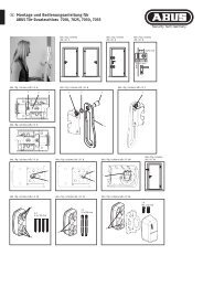
D <strong>Montage</strong>- <strong>und</strong> <strong>Bedienungsanleitung</strong><br />
<strong>für</strong> <strong>ABUS</strong> <strong>Fenster</strong>-Scharnierseiten-Sicherung FAS 101<br />
G <strong>ABUS</strong> Installation and operation instructions<br />
for <strong>ABUS</strong> window hinge security device FAS 101<br />
FTS<br />
10 12<br />
Abb./fig.<br />
schéma<br />
afb./ill. 1a<br />
FTS<br />
69<br />
Flügelblech<br />
Casement plate<br />
Platine d’ancrage<br />
Raamplaat<br />
Lamierina<br />
(per battente)<br />
Abb./fig.<br />
schéma<br />
afb./ill. 1b<br />
<strong>Fenster</strong>/Window<br />
Fenêtre/Raam<br />
Finestra<br />
54<br />
„1“ =<br />
max.<br />
6,5 mm<br />
„2“ =<br />
max.<br />
14 mm<br />
4 1 7<br />
min.<br />
10 mm<br />
18<br />
8<br />
24<br />
Wand<br />
Wall<br />
Le mur<br />
Wand<br />
Parete<br />
123<br />
min. 10 mm<br />
<strong>Fenster</strong>scharnier<br />
Window hinge<br />
Paumelle<br />
Raamscharnier<br />
Cerniera della<br />
finestra<br />
11<br />
D Diese Anleitung ist wie folgt untergliedert:<br />
I. Allgemeine Hinweise IV. Werkzeug<br />
II. Einsatzmöglichkeit V. <strong>Montage</strong>anleitung<br />
III. Packungsinhalt VI. Bedienung<br />
I. Allgemeine Hinweise<br />
Die <strong>Fenster</strong>-Scharnierseiten-Sicherung FAS 101 ist nach DIN 18104-1 <strong>und</strong><br />
VdS 2536 anerkannt. Durch DIN Certco ist FAS 101 zertifiziert „EINBRUCH-<br />
HEMMEND DIN-geprüft“. FAS 101 bietet zusätzlich Schutz gegen unberechtigtes<br />
Eindringen in ihre Räume. Gemäß DIN 18104-1 wird empfohlen,<br />
dass pro 1 Meter <strong>Fenster</strong>höhe rechts <strong>und</strong> links jeweils eine Zusatzsicherung<br />
montiert wird (pro <strong>Fenster</strong>). Polizei <strong>und</strong> Versicherer empfehlen dieses ebenfalls.<br />
Die optimale Schutzwirkung erreichen Sie, wenn Sie entsprechend dieser<br />
<strong>Montage</strong>- <strong>und</strong> <strong>Bedienungsanleitung</strong> vorgehen.<br />
Die Befestigungsschrauben sollten zur Vermeidung von Überdrehung mit<br />
einem geeigneten Werkzeug eingeschraubt <strong>und</strong> von Hand angezogen werden.<br />
Ausschließlich <strong>ABUS</strong>-Befestigungsmaterial einsetzen.<br />
Für eventuell auftretende Verletzungen bzw. Schäden, die bei der <strong>Montage</strong><br />
<strong>und</strong>/oder durch unsachgemäße Handhabung entstehen, übernimmt der<br />
Hersteller keine Haftung!<br />
Ein Zugang des gesamten Objektes muss von außen mittels Schlüssel zu<br />
öffnen sein.<br />
II. Einsatzmöglichkeit<br />
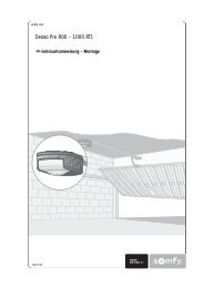
FAS 101 wird auf der Scharnierseite des <strong>Fenster</strong>s oder der <strong>Fenster</strong>tür montiert<br />
<strong>und</strong> eignet sich <strong>für</strong> alle gängigen nach innen öffnende <strong>Fenster</strong>/<strong>Fenster</strong>türen<br />
mit Einhand Dreh- oder -Dreh-Kipp-Beschlägen (Abb. 1a+b). Der Falzstärke<br />
entsprechend muss entweder das Flügelblech 1 oder 2 (7) eingesetzt werden.<br />
Die <strong>Montage</strong> kann auf den Werkstoffen Kunststoff, Holz oder Alu erfolgen.<br />
Die <strong>Fenster</strong>/<strong>Fenster</strong>türen können nach rechts oder links öffnen.<br />
Wahlweise kann die Betätigung der FAS 101 von oben oder unten erfolgen.<br />
Die <strong>Montage</strong> ist <strong>für</strong> Betätigung von unten beschrieben.<br />
FAS 101 wird gr<strong>und</strong>sätzlich auf der Innenseite montiert, das Flügelblech auf<br />
dem <strong>Fenster</strong>flügel <strong>und</strong> die Rahmenleiste auf dem Rahmen.<br />
Bei schlechten Befestigungsmöglichkeiten (Weichholz- oder Kunststofffenster)<br />
sollten mehrere Sicherungen <strong>und</strong> zusätzlich Befestigungsmittel (Befestigungsanker<br />
oder Verb<strong>und</strong>mörtel) eingesetzt werden. Hierzu verwenden Sie<br />
bitte den <strong>ABUS</strong>-Befestigungsanker BA (Kunststoff-, Weichholz-, Alufenster)<br />
oder alternativ das <strong>ABUS</strong>-Befestigungsset IM 100 (Kunststofffenster).<br />
Zu IM 100 benötigen Sie einen geeigneten Verb<strong>und</strong>mörtel,<br />
z.B. der Marke Fischer FIS VS 150C, Hilti HFX oder ein ähnliches Produkt.<br />
<strong>ABUS</strong> BA <strong>und</strong> <strong>ABUS</strong> IM 100 sowie Verb<strong>und</strong>mörtel sind im Handel erhältlich.<br />
Die in Abb. 2 zusätzlich gezeigten <strong>ABUS</strong>-Produkte (FTS) sind ebenfalls im<br />
Handel erhältlich.<br />
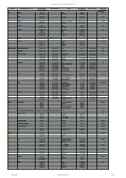
III. Packungsinhalt (Abb. 3)<br />
1. 1 Rahmenleiste 6. 1 Feder<br />
2. 1 Führungshülse 7. 2 x Flügelblech (1+ 2)<br />
3. 1 Druckstift 8. 1 Flügelhaube<br />
4. 1 Clip 9. 1 Rahmenhaube<br />
5. 1 Riegelbolzen<br />
10. Schrauben:<br />
1 Stück 5,5 x 50 mm 2 Stück 3,5 x 25 mm<br />
2 Stück 4,8 x 50 mm 3 Senkschrauben 4,8 x 50 mm<br />
2 Stück 3,5 x 13 mm 1 Senkschrauben 4,8 x 22 mm<br />
11. 1 Satz Unterlagen <strong>für</strong> Flügelblech je 1x1, 2, 3, 4, 8 mm<br />
12. 1 Satz Unterlagen <strong>für</strong> Rahmenleiste je 1x1, 2, 4 mm<br />
IV. <strong>Montage</strong>werkzeug<br />
Kreuzschlitzschraubendreher<br />
Bohrmaschine<br />
Metermaß<br />
Feile, Säge zum Kürzen der Schrauben, ggf. Schraubstock<br />
Bohrtabelle<br />
<strong>für</strong><br />
Schrauben<br />
Ø<br />
5,5 mm<br />
4,8 mm<br />
3,5 mm<br />
In Holz <strong>und</strong> Kunststoff<br />
ohne Metalleinlage<br />
Bohrer Ø<br />
4,0 mm<br />
3,5 mm<br />
In Alu <strong>und</strong> Kunststoff<br />
mit Metalleinlage<br />
Bohrer Ø<br />
4,5 mm<br />
3,5 mm<br />
2,5 mm 3,0 mm<br />
G These instructions are organised in the following sections:<br />
I. General instructions IV. Tools<br />
II. Possible uses V. Installation instructions<br />
III. Pack contents VI. Operation<br />
I. General instructions<br />
The window hinge security device FAS 101 is recognised as complying<br />
with the strict test requirements of DIN 18104-1 and VdS 2536.<br />
FAS 101 is certified by DIN Certco as “BURGLAR RETARDANT DIN tested”.<br />
FAS 101 offers additional protection from unauthorised intruders in your rooms.<br />
DIN 18104-1 recommends that an additional security device should be fitted<br />
on the left and right for every meter in height (per window).<br />
The police and insurance companies also give the same recommendation.<br />
Optimum protection can be achieved by proceeding according to these<br />
installation and operation instructions. To prevent the risk of overtightening,<br />
the fastening screws should by screwed in using a suitable tool and tightened<br />
by hand. Only use <strong>ABUS</strong> fastening material.<br />
The manufacturer does not assume any liability for possible injuries or<br />
damages caused during installation and/or by incorrect handling!<br />
II. Possible use<br />
FAS 101 is mounted on the hinge side of the window or French door and is<br />
suitable for all common windows/French doors opening to the inside with<br />
turn or turn-and-tilt hardware (fig. 1a+b). Depending on the rebate,<br />
casement plate 1 or 2 (7) has to be used. The lock can be fitted to wood,<br />
PVC or aluminium. The windows/French doors can open to the right or left.<br />
The security device FAS 101 can be activated from top or bottom.<br />
The described installation procedure is for activation from the bottom.<br />
FAS 101 is always mounted to the inside, with the casement plate on the<br />
window casement and the frame strip on the frame.<br />
In poor fixture conditions (soft or hollow or foam base and PVC windows with<br />
and without metal inlay and wooden windows) and/or good possibilities for<br />
intrusion from the outside, more security devices and additional fastenings<br />
should be used (composite mortar or fixing bolts). If the frame itself is too<br />
weak for sensible retrofitting, it may be necessary for example to reinforce the<br />
frame.<br />
To do so, please use the <strong>ABUS</strong> fixing bolt BA or alternatively for PVC frames,<br />
the <strong>ABUS</strong> fastening set IM 100. For IM 100 you need a suitable composite<br />
mortar, e.g. Fischer FIS VS 150C or similar. <strong>ABUS</strong> BA and <strong>ABUS</strong> IM 100 are<br />
available from retail stores together with composite mortar.<br />
The <strong>ABUS</strong> products also shown in fig. 2 (FTS) are also available from<br />
retail stores.<br />
III. Pack contents (fig. 3)<br />
1. 1 frame strip 6. 1 spring<br />
2. 1 guide sleeve 7. 2 x casement plate (1+ 2)<br />
3. 1 pressure pin 8. 1 casement cover<br />
4. 1 clip 9. 1 frame cover<br />
5. 1 locking bolt<br />
10. Screws:<br />
1 each 5.5 x 50 mm 2 each 3.5 x 25 mm<br />
2 each 4.8 x 50 mm 3 countersunk screws 4.8 x 50 mm<br />
2 each 3.5 x 13 mm 1 countersunk screws 4.8 x 22 mm<br />
11. 1 set of shims for casement plate, 1x1, 2, 3, 4, 8 mm each<br />
12. 1 set of shims for frame strip, 1x1, 2, 4 mm each<br />
IV. Installation tools<br />
Phillips screwdriver<br />
Drill<br />
Yardstick<br />
Saw, file for shortening the screws, possibly vice<br />
Drilling table<br />
for<br />
screws<br />
Ø<br />
5.5 mm<br />
4.8 mm<br />
3.5 mm<br />
in wood and PVC<br />
without metal inlay<br />
drill bit Ø<br />
4.0 mm<br />
3.5 mm<br />
in aluminium and PVC<br />
with metal inlay<br />
drill bit Ø<br />
4.5 mm<br />
3.5 mm<br />
2.5 mm 3.0 mm
F Ce manuel comporte les chapitres suivants:<br />
I. Conseils d’ordre général IV. Outillage<br />
II. Application V. Instructions d’installation<br />
III. Liste de colisage VI. Utilisation<br />
I. Conseils d’ordre général<br />
La sécurité pour gonds de fenêtre FAS 101 satisfait aux exigences de contrôle<br />
sévères des normes DIN 18104-1 et VdS 2536. Le certificat DIN indique que<br />
FAS 101 a obtenu la qualification «anti-effraction DIN». FAS 101 offre en plus<br />
une protection contre les intrusions par effraction dans votre logement.<br />
Selon la norme DIN 18104-1, il est recommandé de monter une sécurité<br />
complémentaire par mètre de hauteur de fenêtre, à gauche comme à droite.<br />
La police et les compagnies d’assurance le recommandent également.<br />
Pour un effet de protection optimal, suivez les instructions de ce manuel<br />
d’installation et d’utilisation. Afin d’éviter un serrage abusif, vissez et serrez les<br />
vis de fixation à la main et avec un outillage adéquat. Utilisez exclusivement<br />
des accessoires <strong>ABUS</strong>.<br />
Le fabricant n’assume aucune responsabilité pour d’éventuels blessures ou dégâts<br />
causés pendant l’installation et/ou par suite de manipulations inappropriées!<br />
L’ensemble doit être accessible de l’extérieur afin de l’ouvrir au moyen d’une clé.<br />
II. Application<br />
FAS 101 est monté sur le côté des paumelles de la fenêtre ou de la porte-fenêtre<br />
et convient pour toutes les fenêtres/portes-fenêtres courantes, ouvrant vers<br />
l’intérieur et pourvues de quincaillerie ouvrante ou oscillo-battante avec<br />
commande d’une seule main (schéma 1a+b). Suivant l’épaisseur du recouvrement<br />
de la porte, utiliser l’ailette en tôle N° 1 ou 2 (7). L’installation peut être<br />
effectuée sur des cadres en bois, en PVC ou en aluminium. Les fenêtres/portesfenêtres<br />
peuvent s’ouvrir à gauche ou à droite. La commande de FAS 101 peut<br />
être effectuée par le haut ou par le bas. L’installation décrite correspond à une<br />
commande par le bas. FAS 101 est monté en principe du côté intérieur,<br />
la platine d’ancrage sur l’ouvrant et le socle de fixation sur le dormant.<br />
En cas de possibilités de fixation défavorables (fenêtres en bois ou en PVC),<br />
plusieurs sécurités et des fixations supplémentaires (ancre de fixation ou mortier)<br />
doivent être prévues.<br />
Pour cela, utilisez l’ancre de fixation <strong>ABUS</strong> BA (pour fenêtres en PVC,<br />
en bois tendre ou en aluminium) ou l’ensemble de fixations <strong>ABUS</strong> IM 100<br />
(pour fenêtres en PVC).<br />
Pour IM 100, un mortier de fixation approprié est requis, par exemple FIS<br />
VS 150C de la marque Fischer, HFX de la marque Hilti ou un produit similaire.<br />
<strong>ABUS</strong> BA et <strong>ABUS</strong> IM 100 ainsi que le mortier de fixation sont disponibles dans<br />
le commerce.<br />
Les produits <strong>ABUS</strong> complémentaires illustrés en schéma 2 (FTS) sont également<br />
disponibles dans le commerce.<br />
III. Liste de colisage (schéma 3)<br />
1. 1 socle de fixation 6. 1 ressort<br />
2. 1 tuyau de guidage 7. 2 x platine d’ancrage (1+ 2)<br />
3. 1 tige d’appui 8. 1 cache pour platine<br />
4. 1 circlip 9. 1 cache pour socle<br />
5. 1 pêne de verrouillage<br />
10. Vis:<br />
1 pièce de 5,5 x 50 mm 2 pièces de 3,5 x 25 mm<br />
2 pièces de 4,8 x 50 mm 3 vis à tête conique de 4,8 x 50 mm<br />
2 pièces de 3,5 x 13 mm 1 vis à tête conique de 4,8 x 22 mm<br />
11. 1 ensemble d’entretoises pour platine d’ancrage chacun 1x1, 2, 3, 4, 8 mm<br />
12. 1 ensemble d’entretoises pour socle de fixation chacun 1x1, 2, 4 mm<br />
IV. Outillage requis<br />
Tournevis cruciforme<br />
Perceuse<br />
Mètre ruban<br />
Lime, scie pour raccourcir les vis, tournevis<br />
Tableau de perçage<br />
pour<br />
vis<br />
de Ø<br />
5,5 mm<br />
4,8 mm<br />
3,5 mm<br />
dans châssis bois et PVC<br />
sans armature métallique<br />
foret Ø<br />
4,0 mm<br />
3,5 mm<br />
F Instructions de montage et d’utilisation pour<br />
protection gonds de fenêtre <strong>ABUS</strong> FAS 101<br />
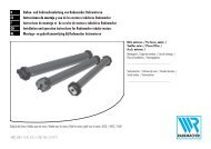
n <strong>Montage</strong>- en bedieningsinstructie voor<br />
<strong>ABUS</strong> scharnierzijde-beveiliging FAS 101<br />
I Istruzioni di montaggio ed uso della sicura<br />
per cerniere di finestre <strong>ABUS</strong> FAS 101<br />
dans châssis aluminium et PVC<br />
avec armature métallique<br />
foret Ø<br />
4,5 mm<br />
3,5 mm<br />
2,5 mm 3,0 mm<br />
n Deze montage- en bedieningsinstructie is als volgt onderverdeeld:<br />
I. Algemeen IV. Gereedschap<br />
II. Toepassing V. <strong>Montage</strong><br />
III. Verpakkingsinhoud VI. Bediening<br />
I. Algemeen<br />
Scharnierbeveiliger FAS 101 voor naar binnen draaiende draai/kiep elementen.<br />
FAS 101 is volgens keuringseisen NEN 5096 SKG gecertificeerd.<br />
De FAS 101 biedt daarnaast bescherming tegen onbevoegd binnendringen van<br />
uw woning. Advies: monteer aan de scharnierzijde voor maximale veiligheid<br />
2 stuks per 1 meter raamhoogte. Op kunststof zonder metalen kern dient<br />
u deze scharnierbeveiliger in combinatie met <strong>ABUS</strong> BA bevestigingsanker te<br />
monteren. Optioneel verkrijgbaar, zie voor montage in de handleiding van BA.<br />
Optimale veiligheid wordt bereikt door nauwkeurig opvolgen van deze<br />
montage- en gebruiksaanwijzing. Om overexpansie of doldraaien van de<br />
bevestigingsschroeven te vermijden, draait u handmatig en met passend<br />
gereedschap de schroeven vast.<br />
Voor eventueel verwondingen en/of schade tijdens montage en/of<br />
door ondesk<strong>und</strong>ig gebruik ontstaan, aanvaardt de fabrikant geen<br />
aansprakelijkheid!<br />
II. Toepassing<br />
De FAS 101 wordt aan de scharnierzijde gemonteerd en is geschikt voor alle<br />
naar binnen draaiende ramen en deuren met draai/kip-beslag (afb. 1a+b).<br />
Afhankelijk van de opdekhoogte moet raamplaat 1 of 2 (7) toegepast worden.<br />
<strong>Montage</strong> mogelijk op hout, kunststof of aluminium. Rechts of links draaiend.<br />
Hoewel de bediening van de vergrendeling van onder- of van bovenaf plaats<br />
kan vinden wordt in deze montage- en bedieningsinstrictie uitgegaan van een<br />
bediening van onderaf.<br />
De FAS 101 wordt uitsluitend aan de binnenzijde gemonteerd;<br />
de raamplaat op het raam of deur en de kozijnlijst op het kozijn.<br />
Bij slechte bevestigingsmogelijkheden (zacht hout of kunststof)<br />
dienen meerdere sloten en extra bevestigingsmiddelen<br />
(bevestigings- of chemische ankers) toegepast te worden.<br />
Hiervoor kunt u het <strong>ABUS</strong> bevestigingsanker BA (zacht hout, kunststof,<br />
aluminium) of als alternatief de <strong>ABUS</strong> bevestigingsset IM 100 (kunststof)<br />
gebruiken (in schroefgat D).<br />
Bij IM 100 heeft u een passend chemisch anker nodig,<br />
bijv. Fischer FIS VS 150C, Hilti HFX of vergelijkbaar.<br />
<strong>ABUS</strong> BA, IM 100 en chemische ankers zijn in de handel verkrijgbaar.<br />
De in afb. 2 extra getoonde <strong>ABUS</strong> producten (FTS) zijn eveneens<br />
in de handel verkrijgbaar.<br />
III. Verpakkingsinhoud (afb. 3)<br />
1. 1 kozijnlijst 4. 1 clip 7. 2 x raamplaat (1+ 2)<br />
2. 1 geleidingshuls 5. 1 vergrendelingspen 8. 1 raamplaat-afdekkap<br />
3. 1 drukstift 6. 1 veer 9. 1 kozijnlijst-afdekkap<br />
10. Schroeven:<br />
1 stuks 5,5 x 50 mm 2 stuks 3,5 x 25 mm<br />
2 stuks 4,8 x 50 mm<br />
2 stuks 3,5 x 13 mm<br />
3 stuks 4,8 x 50 mm met verzonken kop<br />
1 stuks 4,8 x 22 mm met verzonken kop<br />
11. 1 set opvulplaatjes voor raamplaat 1x1, 2, 3, 4 en 8 mm<br />
12. 1 set opvulplaatjes voor kozijnlijst 1x1, 2 en 4 mm<br />
IV. Gereedschap<br />
Kruiskopschroevendraaier<br />
Boormachine<br />
Meetlat<br />
Zaag, vijl en eventueel bankschroef voor het inkorten van de schroeven<br />
Boortabel<br />
voor<br />
schroeven<br />
Ø<br />
5,5 mm<br />
4,8 mm<br />
3,5 mm<br />
in hout en kunststof<br />
zonder metalen kern<br />
boor Ø<br />
4,0 mm<br />
3,5 mm<br />
in aluminium en kunststof<br />
met metalen kern<br />
boor Ø<br />
4,5 mm<br />
3,5 mm<br />
2,5 mm 3,0 mm<br />
classificatie manuele test<br />
zelfstandig<br />
I Queste istruzioni si suddividono nel modo seguente:<br />
I. Istruzioni generali IV. Attrezzi<br />
II. Possibilità d’impiego V. Istruzioni di montaggio<br />
III. Contenuto della confezione VI. Uso<br />
I. Istruzioni generali<br />
La sicura per cerniere di finestre FAS 101 è conforme ai severi requisiti<br />
di controllo della DIN 18104-1 e della VdS 2536.<br />
Con la DIN Certco essa è certificata come «ANTISCASSO conf. DIN».<br />
La FAS 101 garantisce una protezione in più a difesa della Vostra casa.<br />
Secondo DIN 18104-1 si consiglia di montare per ogni metro di altezza<br />
della finestra, una sicura supplementare sul lato destro e una sul lato<br />
sinistro (per ogni finestra). Anche la polizia e le compagnie d’assicurazione<br />
consigliano tali misure.<br />
Si può ottenere una protezione ottimale, procedendo secondo queste istruzioni<br />
di montaggio ed uso. Le viti di fissaggio, per evitarne un serraggio eccessivo,<br />
devono essere avvitate con un utensile adatto e poi serrate a mano.<br />
Impiegare esclusivamente materiale di fissaggio <strong>ABUS</strong>.<br />
Per eventuali ferimenti e/o danni, che si verificano durante il montaggio e/o<br />
per maneggio indebito, il produttore non si assume alcuna responsabilità!<br />
II. Possibilità d’impiego<br />
La FAS 101 viene montata sul lato della cerniera della finestra o della portafinestra<br />
ed è adatta per tutte le normali finestre e porte-finestre che si aprono<br />
verso l’interno, con guarnizioni metalliche girevoli o girevoli a bilico<br />
(ill. 1a+b). Secondo losspessore della finestzra si posa la lamierina 1 o 2 (7).<br />
Si può montare la FAS 101 su legno, plastica o alluminio.<br />
Le finestre/porte-finestre possono aprirsi verso destra o verso sinistra.<br />
A scelta la FAS 101 si può azionare dall’alto o dal basso.<br />
Il montaggio è descritto per azionamento dal basso.<br />
Di solito la FAS 101 viene montata all’interno, la lamiera del battente<br />
sul battente della finestra ed il listello del telaio sul telaio.<br />
Se le possibilità di fissaggio sono scadenti (sottofondo morbido o vuoto<br />
o riempito con espanso e finestre in plastica con o senza inserto metallico<br />
e finestre in legno) e le possibilità di effrazione dall’esterno sono buone,<br />
si dovrebbero utilizzare più sicure e mezzi di fissaggio supplementari<br />
(malta o avvitamento passante o bullone di fissaggio).<br />
Se i telai stessi sono troppo deboli, per poterli allestire adeguatamente<br />
in un secondo tempo, potrebbe essere consigliabile rinforzare, per esempio,<br />
i telai stessi.<br />
Allo scopo utilizzare per favore il bullone di fissaggio <strong>ABUS</strong> BA o come<br />
alternativa, nel caso di telai in plastica, il kit di fissaggio <strong>ABUS</strong> IM 100.<br />
Per il IM 100 serve una malta adatta, p.e. della marca Fischer FIS VS 150C<br />
o un prodotto simile. <strong>ABUS</strong> BA e <strong>ABUS</strong> IM 100 come anche la malta si possono<br />
acquistare.<br />
Anche i prodotti <strong>ABUS</strong> (FTS) raffigurati nel’ill. 2 (FTS) si possono acquistare.<br />
III. Contenuto della confezione (ill. 3)<br />
1. listello del telaio 6. 1 molla<br />
2. boccola di guida 7. 2 x lamierina (per battente) (1+ 2)<br />
3. 1 perno di spinta 8. 1 coperchietto della lamierina per battente<br />
4. 1 clip 9. 1 coperchietto per listello del telaio<br />
5. 1 perno del chiavistello<br />
10. Viti:<br />
1 vite da 5,5 x 50 mm 2 viti da 3,5 x 25 mm<br />
2 viti da 4,8 x 50 mm 3 viti a testa svasata da 4,8 x 50 mm<br />
2 viti da 3,5 x 13 mm 3 viti a testa svasata da 4,8 x 22 mm<br />
11. 1 kit di spessori per ogni lamierina del battente, ciascuno 1 x 1, 2, 3,4,8 mm<br />
12. 1 kit di spessori per ogni listello del telaio ciascuno 1x1, 2, 4 mm<br />
IV. Attrezzi da montaggio<br />
Cacciavite a stella (con punta magnetica)<br />
Trapano<br />
Sega, lima per accorciare le viti, in caso una morsa<br />
Tabella di trapanazioni<br />
per<br />
viti<br />
Ø<br />
5,5 mm<br />
4,8 mm<br />
3,5 mm<br />
inbraakwerendheidsklasse<br />
NEN5096/ENV1630<br />
in legno e plastica<br />
senza inserto metallico<br />
punta da trapano Ø<br />
4,0 mm<br />
3,5 mm<br />
contacttijd /<br />
gereedschapsset<br />
RC 2 3 min. / A<br />
in alluminio e plastica<br />
con inserto metallico<br />
punta da trapano Ø<br />
4,5 mm<br />
3,5 mm<br />
2,5 mm 3,0 mm<br />
gebruik BA-anker<br />
houten kozijnen kunststof kozijnen<br />
zonder<br />
<strong>ABUS</strong> bevestigingsanker<br />
in combinatie met<br />
<strong>ABUS</strong> bevestigingsanker
Abb./fig./schéma/afb./ill. 4<br />
Abb./fig.<br />
schéma<br />
afb./ill. 6a<br />
Abb./fig.<br />
schéma<br />
afb./ill. 6b<br />
Riegelbolzen<br />
Locking bolt<br />
Pêne de verrouillage<br />
Vergrendelingspen<br />
Perno del chiavistello<br />
Abb./fig./schéma/afb./ill. 9<br />
D<br />
D<br />
D<br />
Rahmenleiste<br />
Frame strip<br />
Platine de fixation<br />
Kozijnlijst<br />
Listello del telaio<br />
Abb./fig.<br />
schéma<br />
afb./ill. 6c<br />
C<br />
<strong>ABUS</strong> - Das gute Gefühl der Sicherheit<br />
Abb./fig./schéma/afb./ill. 5<br />
Abb./fig./schéma/afb./ill. 7 Abb./fig./schéma/afb./ill. 8<br />
Abb./fig./schéma/afb./ill. 10<br />
D Technische Änderungen vorbehalten. Für Irrtümer <strong>und</strong> Druckfehler keine Haftung. <strong>ABUS</strong> © 2011<br />
G Subject to technical alterations. No liability for mistakes and printing errors. <strong>ABUS</strong> © 2011<br />
B<br />
A<br />
B<br />
(x)<br />
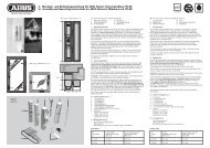
D V. <strong>Montage</strong>anleitung:<br />
Wichtige Hinweise:<br />
1. Vor der <strong>Montage</strong> prüfen Sie bitte die Einstellung des <strong>Fenster</strong>s.<br />
Stellen Sie sicher, dass sich das <strong>Fenster</strong>/die <strong>Fenster</strong>tür einwandfrei<br />
öffnen <strong>und</strong> schließen lässt.<br />
2. Messen Sie auch nach, ob die in Abb. 1a+b angegebenen Maße<br />
an Ihrem <strong>Fenster</strong>/Ihrer <strong>Fenster</strong>tür vorhanden sind.<br />
3. Die Bohrlochtiefen bzw. die Schraubenlängen müssen auf die<br />
örtlichen Gegebenheiten abgestimmt werden, ebenso die empfohlene<br />
Schrägverschraubung bei Holzfenstern.<br />
4. Austreten des Bohrers bzw. der Schrauben auf der Rückseite<br />
vermeiden! Ggf. mit Bohranschlag arbeiten oder die vorhandenen<br />
Schrauben kürzen. Beim Bohren keine beweglichen Teile, Dichtungen<br />
oder Glasscheiben verletzen.<br />
<strong>Montage</strong>:<br />
Falls die Flügelhaube (8) <strong>und</strong> Rahmenhaube (9) montiert sind,<br />
diese zunächst vorsichtig abnehmen.<br />
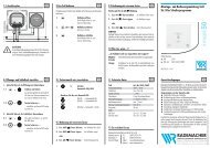
1. Riegelbolzen (5) mit dem langen Ende voran in Rahmenleiste (1) stecken,<br />
an das vorhandene <strong>Fenster</strong>scharnier halten (Abb. 4), so dass der Mittelpunkt<br />
des Riegelbolzens (5) mit der Drehachse des oberen <strong>und</strong> unteren<br />
Scharniers übereinstimmt (± 1 mm erlaubt). Rahmenleiste (1) ggf. mit<br />
Unterlagen (12) ausgleichen.<br />
2. Abstand (X) der Rahmenleiste (1) zum <strong>Fenster</strong>flügel messen;<br />
Hilfsmittel: Unterlagen (Abb. 5).<br />
3. Riegelbolzen (5) entnehmen. Rahmenleiste (1) auf gewünschte <strong>Montage</strong>position<br />
bringen <strong>und</strong> darauf achten, dass der ermittelte Abstand (X) zum<br />
<strong>Fenster</strong>flügel (Drehachse) genau eingehalten wird (Abb. 5).<br />
4. Bohrlöcher A + B anzeichnen <strong>und</strong> vorbohren (s. Bohrtabelle).<br />
Rahmenleiste (1) ggf. mit den Unterlagen (12) mit Schrauben<br />
A = 5,5x 50 mm, B = 4,8 x 50 mm handfest anschrauben.<br />
5. Druckstift (3) von oben in die Führungshülse (2) so einsetzen (Abb. 6a),<br />
dass der Druckstift (3) unten ca. 30 mm aus der Führungshülse (2)<br />
herausragt (Abb. 6b), ggf. mehrmals etwas drehen. Riegelbolzen (5)<br />
mit dem breiten Ende voraus in die Führungshülse (2)einschieben <strong>und</strong><br />
Feder (6) aufstecken (Abb. 6c).<br />
6. Komplette Einheit von unten enganliegend in die Rahmenleiste (1)<br />
über den Widerstand der Blattfeder hinaus einschieben. Druckstift (3)<br />
nicht eindrücken (Abb. 7).<br />
7. Clip (4) auf die Führungshülse (2) drücken, so dass der Clip (4) rechts<br />
<strong>und</strong> links in die Rahmenleiste (1)einrastet (Abb. 8). Rahmenhaube (9)<br />
von unten über den Druckstift (3) auf die Rahmenleiste (1) stecken<br />
<strong>und</strong> fest andrücken. <strong>Fenster</strong> öffnen <strong>und</strong> überprüfen, ob beide Seiten<br />
des Clips fest eingerastet sind.<br />
8. Flügelblech (7)in die Rahmenleiste (1) einsetzen <strong>und</strong> ggf. mit Unterlagen<br />
(11) ausgleichen. Druckstift (3) eindrücken, so dass die FAS 101<br />
verriegelt ist. Flügelblech (7) mittig ausrichten <strong>und</strong> Bohrlöcher C<br />
anzeichnen <strong>und</strong> mittig vorbohren (Abb. 9) (s. Bohrtabelle).<br />
Je nach Dicke des Unterlagenpaketes (11) Flügelblech (7) mit<br />
Schrauben 3,5 x 13 mm bzw. 3,5 x 25 mm handfest anschrauben.<br />
Funktion des <strong>Fenster</strong>s überprüfen. Schließen <strong>und</strong> öffnen, ggf. nachjustieren.<br />
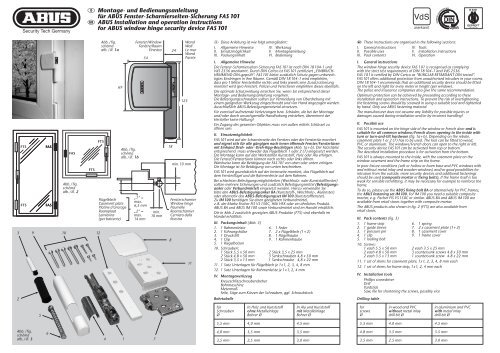
Schraublöcher D vorbohren (Abb. 9) (s. Bohrtabelle).<br />
Bei Holzfenstern die beiden vorderen Löcher leicht schräg, bis max. 20°<br />
Neigung Richtung <strong>Fenster</strong>mitte vorbohren.<br />
Hinweis: Bei umlaufenden <strong>Fenster</strong>beschlägen beim Bohren des<br />
mittleren Schraubloches D nicht das <strong>Fenster</strong>getriebe beschädigen.<br />
9. Flügelblech (7) anschrauben: Bei <strong>Fenster</strong>n ohne umlaufenden Beschlag<br />
mit 3 Schrauben 4,8 x 50 mm. Bei <strong>Fenster</strong>n mit umlaufendem Beschlag<br />
mit 2 Schrauben 4,8 x 50 mm <strong>und</strong> 1 Schraube 4,8 x 22 mm beim<br />
mittleren Schraubloch D.<br />
10. Flügelhaube (8) aufdrücken (Abb. 10).<br />
VI. Bedienung<br />
• FAS 101 wird in die normale Betätigung des <strong>Fenster</strong>s einbezogen.<br />
• In geschlossenem Zustand des <strong>Fenster</strong>s Druckstift generell eindrücken<br />
bis er einrastet. Für normale Drehöffnung ist keine weitere Betätigung<br />
notwendig.<br />
• Zum Kippen des <strong>Fenster</strong>s Druckstift nach dem Kugelschreiberprinzip<br />
ausrasten, sodass er ca. 30 mm herausfährt.<br />
• Nach dem Schließen des <strong>Fenster</strong>s Druckstift wieder eindrücken<br />
bis er einrastet.<br />
G V. Installation instructions:<br />
• Before installation, please check the setting of the window<br />
or French door.<br />
• If necessary, readjust the fittings so that the window (French door)<br />
opens and closes perfectly.<br />
• Also check whether your window/French door complies with the<br />
dimensions shown in fig. 1a+b.<br />
• The depths of the drilled holes and screw lengths must be adjusted<br />
to the local conditions, also the recommended angled screw<br />
connection wooden windows.<br />
• Avoid the drill or screws from coming out at the back!<br />
Possibly work with drill stopper or shorten the existing screws.<br />
• When drilling, do not damage any moving parts, seals or glass panes.<br />
Installation:<br />
If the casement cover (8) and frame cover (9) are fitted,<br />
remove them carefully first.<br />
1. Push the locking bolt (5) into the frame strip (1) with the long end first,<br />
hold against the existing window hinge (fig. 4) so that the middle point<br />
of the locking bolt (5) corresponds to the turning axis of the upper and<br />
lower hinge (± 1 mm allowed). If necessary, use shims (12) to adjust<br />
the frame strip (1).<br />
2. Measure the distance (X) of the frame strip (1) to the window casement<br />
(aid: shims).<br />
3. Take the locking bolt (5) out. Apply the frame strip (1) in the required<br />
fitting position, keeping exactly to the measured distance (X) to the<br />
window casement (turning axis) (fig. 5).<br />
4. Mark and pre-drill holes A and B (see drilling table).<br />
Screw frame strip (1) hand tight possibly with the shims (12),<br />
using screws A = 5.5 x 50 mm, B = 4.8 x 50 mm.<br />
5. Insert the pressure pin (3) into the guide sleeve (2) from above (fig. 6a)<br />
so that the pressure pin (3) protrudes approx. 30 mm from the guide<br />
sleeve (2) (fig. 6b), possibly turning several times. Push the locking<br />
bolt (5) into the guide sleeve (2) with the wide end first and put the<br />
spring (6) in position (fig. 6c).<br />
6. Push the whole unit from below into the frame strip (1) in a tight fit<br />
over and beyond the resistance of the leaf spring. Do not press pressure<br />
pin (3) in (fig. 7).<br />
7. Push the clip (4) onto the guide sleeve (2) so that the clip (4) engages<br />
in the frame strip (1) on the right and left (fig. 8). Push the frame<br />
cover (9) over the pressure pin (3) from below onto the frame strip (1)<br />
and press on firmly.<br />
Open the window and check whether both sides of the clip have<br />
engaged firmly.<br />
8. Insert the casement plate (8) in the frame strip (1) and line with shims<br />
(11) if necessary. Press the pressure pin (3) in so that FAS 101 is locked.<br />
Align casement plate (7) centrally; mark and pre-drill holes C in the<br />
middle (fig. 9): (see drilling table). Depending on the thickness of the<br />
shim package (11), screw the casement plate (7) on hand tight using<br />
screws 3.5 x 13 mm resp. 3.5 x 25 mm.<br />
Check that the window functions: Close and open, adjust if necessary.<br />
Pre-drill screw holes D (fig. 9) (see drilling table). On wooden windows<br />
pre-drill the two front holes slightly at an angle, up to max. 20° in the<br />
direction of the window center<br />
Note: For peripheral window hardware, do not damage the window<br />
gear when drilling the middle screw hole D.<br />
9. Screw on the casement plate (7): for windows without peripheral hardware,<br />
use 3 screws 4.8 x 50 mm. For windows with peripheral hardware,<br />
use 2 screws 4.8 x 50 mm and 1 screw 4.8 x 22 mm in middle hole D.<br />
10. Press on the casement cover (8) (fig. 10).<br />
VI. Operation<br />
• FAS 101 is integrated in the normal operation of the window.<br />
• When the window is closed, generally press the pressure pin until<br />
it engages. No other operation is required when turning the window<br />
open normally.<br />
• To tilt the window, release the pressure pin using the “ballpoint pen”<br />
principle so that it comes approx. 30 mm out.<br />
• After closing the window, press the pressure pin in again until it locks.<br />
www.abus.com
F V. Instructions d’installation:<br />
Indications importantes:<br />
• Avant l’installation, contrôlez l’ouverture de la fenêtre. Assurezvous<br />
que la fenêtre/porte-fenêtre ouvre et ferme parfaitement.<br />
• Vérifiez si votre fenêtre/porte-fenêtre comporte les dimensions<br />
indiquées en schéma 1a+b.<br />
• Les profondeurs de perçage ou plutôt les longueurs des vis ainsi que<br />
les pas de vis en biais sur les fenêtres en bois doivent être adaptées<br />
aux conditions locales.<br />
• Evitez le dépassement de perçage ou de vis sur la face arrière!<br />
Le cas échéant, utilisez une butée de perçage ou raccourcissez<br />
les vis de fixation.<br />
• Lors du perçage, évitez d’endommager les éléments mobiles,<br />
les joints ou les vitres.<br />
Installation:<br />
Si le cache pour platine (8) et le cache pour socle (9) sont montés,<br />
déposez-les avec précaution.<br />
1. Insérez le pêne de verrouillage (5) avec le côté allongé vers l’avant dans<br />
le socle de fixation (1) et maintenez-le contre la paumelle existante<br />
(schéma 4), de façon à ce que l’axe médian du pêne de verrouillage (5)<br />
soit aligné sur l’axe de pivotement des paumelles supérieure et inférieure<br />
(tolérance de ± 1 mm). Ajustez le socle de fixation (1) au moyen des<br />
entretoises (12).<br />
2. Mesurez la distance (X) entre le socle de fixation (1) et l’ouvrant.<br />
Aides: entretoises (schéma 5).<br />
3. Retirez le pêne de verrouillage (5). Placez le socle de fixation (1) à la<br />
position désirée en prenant soin de maintenir avec précision la distance<br />
mesurée (X) par rapport à l’ouvrant (axe de pivotement) (schéma 5).<br />
4. Tracez et préforez les positions de perçage A et B (voir tableau de perçage).<br />
Fixez le socle de fixation (1) au moyen des vis A = 5,5 x 50 mm,<br />
B = 4,8 x 50 mm et éventuellement des entretoises (12) et serrez à la main.<br />
5. Insérez la tige d’appui (3) par le haut dans le tuyau de guidage (2) de telle<br />
façon (schéma 6a), qu’elle dépasse du bas du tuyau (2) d’environ 30 mm<br />
(schéma 6b), en la faisant éventuellement pivoter à plusieurs reprises.<br />
Insérez le pêne de verrouillage (5) avec l’extrémité large vers l’avant dans<br />
le tuyau de guidage (2) et montez le ressort (6) (schéma 6c).<br />
6. Insérez l’ensemble complet par le bas dans le socle de fixation (1)<br />
en comprimant le ressort. N’enfoncez pas la tige d’appui (3) (schéma 7).<br />
7. Posez le circlip (4) sur le tuyau de guidage (2), de façon à ce qu’il<br />
s’engage à gauche et à droite dans le socle de fixation (1) (schéma 8).<br />
Posez et clipsez le cache pour platine (9) par-dessus l’extrémité inférieure<br />
de la tige d’appui (3) sur le socle de fixation (1). Ouvrez la fenêtre et<br />
contrôlez si les deux côtés du circlip sont fermement engagés.<br />
8. Placez la platine d’ancrage (7) dans le socle de fixation (1) et ajustez-le<br />
éventuellement au moyen des entretoises (11). Enfoncez la tige d’appui<br />
(3), de façon à verrouiller FAS 101. Alignez la platine de fixation (7) au<br />
centre et tracez les centres de perçage C puis préforez (schéma 9)<br />
(voir tableau de perçage). Fixez la platine de fixation (7) à la main avec<br />
des vis de 3,5 x 13 mm ou de 3,5 x 25 mm en fonction de l’épaisseur<br />
des entretoises (11).<br />
Contrôlez le bon fonctionnement de la fenêtre. Ouvrez et fermez<br />
la fenêtre et ajustez le cas échéant. Pré-percer les fixations des vis D<br />
(schéma 9) (voir tableau de perçage). Sur des fenêtres en bois, pré-percer<br />
les 2 trous de devant avec une inclinaison de maximum 20° en direction<br />
du milieu de la fenêtre.<br />
Indication:<br />
Si la fenêtre est équipée d’une quincaillerie mobile, évitez d’endommager<br />
le mécanisme de fenêtre lors du perçage de la fixation de vis centrale D.<br />
9. Vissez la platine de fixation (7). Sur les fenêtres sans quincaillerie mobile,<br />
avec 3 vis de 4,8 x 50 mm. Sur des fenêtres avec quincaillerie mobile, avec<br />
2 vis de 4,8 x 50 mm et 1 vis de 4,8 x 22 mm pour la fixation centrale D.<br />
10. Clipsez le cache pour platine (8) (schéma 10).<br />
VI. Utilisation<br />
• FAS 101 est intégré dans les manipulations normales de la fenêtre.<br />
• Avec la fenêtre en position fermée, enfoncez la tige d’appui<br />
jusqu’à ce qu’elle verrouille. Pour une ouverture battante normale,<br />
aucune intervention complémentaire n’est requise.<br />
• Pour faire osciller la fenêtre, déverrouillez la tige d’appui selon<br />
le principe du stylo, de façon à ce qu’il dépasse d’environ 30 mm.<br />
• Après la fermeture de la fenêtre, enfoncez la tige d’appui jusqu’à<br />
ce qu’elle s’enclenche.<br />
n V. <strong>Montage</strong>:<br />
Belangrijke aanwijzingen:<br />
1. Voor de montage dient u de afstelling van het raam resp.<br />
de deur te controleren.<br />
Zorg ervoor dat het raam / de deur probleenloos geopend<br />
en gesloten kan worden.<br />
2. Meet na of de in afb. 1a+b aangegeven afmetingen daadwerkelijk<br />
beschikbaar zijn.<br />
3. De boordieptes en schroeflengten moeten aan het gevelelement<br />
aangepast worden. Evenals de aanbevolen schuine verschroeving<br />
bij houten gevelelementen.<br />
4. Voorkom doorboren en -schroeven.<br />
Eventueel met een booraanslag werken of de schroeven inkorten.<br />
Bij het boren geen beslag, afdichtingen of ruiten beschadigen.<br />
<strong>Montage</strong>:<br />
Indien de afdekkappen (8 + 9) van de raamplaat (7) en de kozijnlijst (1)<br />
reeds aangebracht zijn deze voorzichtig verwijderen.<br />
1. Steek de vergrendelingpen (5) met het langste eind in de kozijnlijst (1)<br />
en houd dit geheel zo tegen het kozijn (afb. 4) dat het hart van de van de<br />
vergrendelingspen (5) in lijn staat met het draaipunt van de scharnieren<br />
(afwijking van max. 1 mm is toegestaan). De kozijnlijst (1) eventueel met<br />
opvulplaatjes (12) uitvullen.<br />
2. Meet de afstand (x) tot de raamkant; eventueel kunnen de diverse<br />
opvulplaatjes hierbij als hulpmiddel dienen (afb. 5).<br />
3. Verwijder de vergrendelingspen (5) en plaats de kozijnlijst (1) op de<br />
gewenste montagepositie (let op afstand x) tegen het kozijn (afb. 5).<br />
4. Teken de boorgaten A+B af en boor ze voor (zie boortabel).<br />
Monteer de kozijnlijst (1) incl. eventuele opvulplaatjes (12) met de<br />
schroeven 5,5 x 50 mm. (A) en 4,8 x 50 mm (B) (handvast!).<br />
5. Plaats de drukstift (3) van boven af in de geleidingshuls (2) (afb. 6a)<br />
zodat deze onder ca. 30 mm uitsteekt (eventueel de drukstift (3) hiervoor<br />
iets draaien)(afb. 6b). Steek de vergrendelingspen (5) met het dikste eind<br />
in de geleidingshuls (2) en breng de veer (6) aan (afb. 6c).<br />
6. Plaats vervolgens het geheel van onder af en over de weerstand van de<br />
bladveer heen in de kozijnlijst (1). Drukstift (3) niet indrukken (afb. 7)!<br />
7. Druk clip (4) zo op de geleidingshuls (2) dat hij links en rechts op de<br />
kozijnlijst (1) klikt (afb. 8). De kozijnlijst-afdekkap (9) van onder af over<br />
de drukstift (3) op de kozijnlijst (1) steken en vast aandrukken. Open<br />
het raam en controleer of beide zijden van de clip (4) goed vastzitten.<br />
8. Plaats de raamplaat (7) incl. eventuele opvulplaatjes (11) op de juiste<br />
montagepositie tegen het raam en druk drukstift (3) in zodat de FAS 101<br />
vergrendeld is. Richt de raamplaat (7), teken de boorgaten C (D nog niet!)<br />
af en boor ze voor (zie boortabel) . Afhankelijk van de gebruikte<br />
opvulplaatjes (11) de raamplaat (7) met 3,5 x 13 mm of 3,5 x 25 mm<br />
schroeven monteren (handvast!).<br />
Bediening van het raam controleren; sluiten / openen en eventueel<br />
bijstellen. Vervolgens schroefgaten D voorboren (afb. 9) (zie boortabel).<br />
Bij houten gevelelementen de beide aten vooraan licht schuin, tot max.<br />
20°, richting het midden van het raam voorboren.<br />
Opmerking: bij rondom doorlopend beslag bij het boren van het<br />
middelste schroefgat D niet het beslag beschadigen.<br />
9. Breng vervolgens de schroeven in de boorgaten D van de raamplaat (7)<br />
aan: bij ramen zonder rondom doorlopend beslag met 3 4,8 x 50 mm<br />
schroeven en bij ramen met rondom doorlopend beslag met 2<br />
4,8 x 50 mm en 1 4,8 x 22 mm schroef in het middelste schroefgat D.<br />
10. Druk de raamplaat-afdekkap (8) op de raamplaat (7) (afb.10).<br />
VI. Bediening<br />
• De FAS 101 wordt bij de normale functies van het raam betrokken.<br />
• Indien het raam gesloten is de drukstift altijd indrukken.<br />
Bij het draaien van het raam is geen verdere bediening nodig<br />
en scharniert de FAS 101 mee.<br />
• Voor het kiepen van het raam dient de FAS 101 ontgrendeld te worden<br />
door de drukstift als een balpen in te drukken.<br />
• Na het sluiten van het raam de drukstift weer indrukken zodat het<br />
raam weer vergrendeld is.<br />
F Nous nous réservons le droit de toutes modifications techniques. Nous n’assumons aucune responsabilité pour des erreurs ou défauts d’impression éventuels. <strong>ABUS</strong> © 2011<br />
n Technische wijzigingen voorbehouden. Geen aansprakelijkheid voor vergissingen en drukfouten. <strong>ABUS</strong> © 2011<br />
I Ci si riservano modifiche tecniche. Per errori e refusi di stampa non ci si assume alcuna responsabilità. <strong>ABUS</strong> © 2011<br />
I V. Istruzioni per il montaggio:<br />
Avvertenze importanti:<br />
• Prima del montaggio verificare per favore la regolazione della finestra<br />
risp. della porta finestra.<br />
• Se necessario registrare nuovamente i ferramenti affinché la finestra<br />
(la porta-finestra) si chiuda e si apra perfettamente.<br />
• Verificare anche che le misure indicate nell’ill. 1a+b esistano nelle<br />
vostre finestre/porte-finestre.<br />
• Le profondità per trapanare i fori, risp. le lunghezze delle viti devono<br />
essere adattate alle condizioni particolari. Anche l’avvitazione<br />
diagonale a finestre in legno.<br />
• Evitare che la punta del trapano risp. la vite fuoriesca dall’altra parte!<br />
Se necessario lavorare con arresto del trapano o accorciare le viti.<br />
• Quando si trapana, non danneggiare parti mobili, guarnizioni o vetri.<br />
Montaggio:<br />
Montaggio della scatola della serratura:<br />
Se il coperchietto per la lamierina del battente (8) e il coperchietto del<br />
listello del telaio (9) sono montati, prima toglierli con cautela.<br />
1. Infilare il perno del chiavistello con l’estremità lunga in avanti nel listello<br />
del telaio (1), tenere sulla cerniera già esistente della finestra (ill. 4),<br />
in modo che il punto centrale del perno del chiavistello (5) coincida<br />
(è permesso ± 1 mm) con l’asse di rotazione della cerniera superiore<br />
ed inferiore. In caso compensare il listello del telaio (1) con spessori (12).<br />
2. Misurare la distanza (X) del listello del telaio (1) rispetto al battente della<br />
finestra (mezzi di ausilio: spessori).<br />
3. Rimuovere il perno del chiavistello. Portare nella posizione di montaggio<br />
desiderata il listello del telaio (1) e fare attenzione che la distanza (X)<br />
accertata rispetto al battente della finestra (asse di rotazione) venga<br />
mantenuta esattamente (ill. 5).<br />
4. Disegnare e trapanare i fori A + B (vedi tabella trapanazioni).<br />
Se necessario avvitare saldamente a mano il listello del telaio (1)<br />
con gli spessori (12) con viti A = 5,5 x 50 mm, B = 4,8 x 50 mm.<br />
5. Inserire dall’alto il perno di spinta (3) nella boccola di guida (2) (ill. 6a)<br />
in modo tale che il perno di spinta (3) fuoriesca in basso di circa 30 mm<br />
dalla boccola di guida (2) (ill. 6b), in caso girare un po’ più volte.<br />
Infilare il perno del chiavistello (5) con l´estremità larga in avanti<br />
nella boccola di guida (2) e infilare la molla (6) (ill. 6c).<br />
6. Infilare l’unità completa dal basso, ben aderente nel listello del telaio (1)<br />
superando la resistenza delle molle a lamina. Non inserire premendo<br />
il perno di spinta (3) (ill. 7).<br />
7. Mettere premendo il clip (4) sulla boccola di guida (2) in modo che<br />
il clip (4) a destra e a sinistra si innesti nel listello del telaio (1) e premere<br />
saldamente (ill. 8). Aprire la finestra e verificare che tutti due i clip si siano<br />
innestati saldamente.<br />
8. Inserire la lamierina del battente (7) nel listello del telaio (1) e in caso<br />
compensare con spessori (11). Inserire premendo il perno di spinta in<br />
modo che la FAS 101 sia bloccata. Allineare centrata la lamierina del<br />
battente (7) e disegnare i fori C e trapanare centratamene (ill. 9);<br />
(vedi tabella trapanazioni). A seconda dello spessore del pacco di spessori<br />
(11) avvitare a mano saldamente la lamierina del battente (7) con viti<br />
3,5 x 13 mm rsp. 3,5 x 25 mm.<br />
Controllare il funzionamento della finestra. Chiudere ed aprire, in caso<br />
registrare. Trapanare i fori per viti D (ill. 9) (Vedi tabella trapanazioni).<br />
Da finestre in legno forare i due buchi con una inclinazione di al massimo<br />
20° in direzione del centro della finestra<br />
Avvertenza: Con serramenti delle finestre poste su tutto il perimetro<br />
della finestra, non danneggiare il meccanismo della finestra quando<br />
si trapana il foro per viti centrale D<br />
9. Avvitare la lamierina del battente (7): con le finestre senza serramenti<br />
tutt’intorno, usare 3 viti da 4,6 x 50 mm. Con le finestre con serramenti<br />
su tutto il perimetro, avvitare con 2 viti da 4,8 x 50 mm ed 1 vite<br />
4,8 x 22 mm, per il foro centrale D.<br />
10. Attaccare premendo il coperchietto della lamierina del battente (8) (ill. 10).<br />
VI. Uso<br />
• FAS 101 viene azionata con il normale azionamento della finestra.<br />
• Con finestra chiusa, in generale si può inserire il perno a spinta fino a<br />
che si innesta. Per normale apertura girevole, non serve fare nient’altro.<br />
• Per aprire a ribalta la finestra disinnestare il perno a spinta come<br />
se fosse una penna a sfera, in modo che esca di circa 30 mm.<br />
• Dopo aver chiuso la finestra, reinserire premendo il perno a spinta<br />
fino a che si innesta.<br />
www.abus.com<br />
390332 1/11