und Bedienungsanleitung für ABUS Fenster-Universalschloss FTS ...
und Bedienungsanleitung für ABUS Fenster-Universalschloss FTS ...
und Bedienungsanleitung für ABUS Fenster-Universalschloss FTS ...

You also want an ePaper? Increase the reach of your titles
YUMPU automatically turns print PDFs into web optimized ePapers that Google loves.
<strong>FTS</strong><br />
<strong>FTS</strong><br />
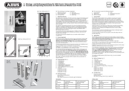
Abb./fig.<br />
schéma<br />
Afb./ill. 3<br />
FAS<br />
FAS<br />
7<br />
8<br />
D Montage- <strong>und</strong> <strong>Bedienungsanleitung</strong> <strong>für</strong> <strong>ABUS</strong> <strong>Fenster</strong>-<strong>Universalschloss</strong> <strong>FTS</strong> 88<br />
G Assembly and Operating Instructions for <strong>ABUS</strong> Universal Window Lock <strong>FTS</strong> 88<br />
Abb./fig./schéma/afb./ill. 2<br />
FAS<br />
<strong>FTS</strong><br />
<strong>FTS</strong><br />
5<br />
134<br />
max. 30<br />
4 1 3<br />
2 6<br />
Abb./fig./schéma/afb./ill. 1<br />
32<br />
<strong>Fenster</strong>rahmen<br />
Frame<br />
Cadre<br />
Kozijn<br />
Telaio<br />
25<br />
<strong>Fenster</strong>flügel<br />
Window<br />
Battant de fenêtre<br />
Raam<br />
Battente<br />
25<br />
D Diese Anleitung ist wie folgt untergliedert:<br />
I. Allgemeine Hinweise IV. Werkzeug<br />
II. Einsatzmöglichkeit V. Montageanleitung<br />
III. Packungsinhalt VI. Bedienung<br />
I. Allgemeine Hinweise<br />
Das <strong>Fenster</strong>-<strong>Universalschloss</strong> <strong>FTS</strong> 88 ist nach den strengen Prüfanforderungen<br />
der DIN 18104-1 <strong>und</strong> VdS 2536 anerkannt. Durch DIN Certco ist <strong>FTS</strong> 88<br />
zertifiziert „EINBRUCHHEMMEND DIN-geprüft“. <strong>FTS</strong> 88 bietet zusätzlich<br />
Schutz gegen unberechtigtes Eindringen in Ihre Räume. Gemäß DIN 18104-1<br />
wird empfohlen, dass pro 1 Meter <strong>Fenster</strong>höhe rechts <strong>und</strong> links jeweils eine<br />
Zusatzsicherung montiert wird (pro <strong>Fenster</strong>). Polizei <strong>und</strong> Versicherer empfehlen<br />
dieses ebenfalls.<br />
Die optimale Schutzwirkung erreichen Sie, wenn Sie entsprechend dieser<br />
Montage- <strong>und</strong> <strong>Bedienungsanleitung</strong> vorgehen. Die Befestigungsschrauben<br />
sollten zur Vermeidung von Überdrehung mit einem geeigneten Werkzeug<br />
eingeschraubt <strong>und</strong> von Hand angezogen werden. Ausschließlich <strong>ABUS</strong>-<br />
Befestigungsmaterial einsetzen.<br />
Für eventuell auftretende Verletzungen bzw. Schäden, die bei der Montage<br />
<strong>und</strong>/oder durch unsachgemäße Handhabung entstehen, übernimmt der<br />
Hersteller keine Haftung!<br />
Ein Zugang des gesamten Objektes muss von außen mittels Schlüssel<br />
zu öffnen sein.<br />
II. Einsatzmöglichkeit<br />
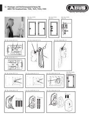
<strong>FTS</strong> 88 wird auf der Griffseite des <strong>Fenster</strong>s oder der <strong>Fenster</strong>tür montiert <strong>und</strong><br />
eignet sich <strong>für</strong> alle gängigen nach innen öffnende <strong>Fenster</strong>/<strong>Fenster</strong>türen<br />
mit Dreh- oder Dreh-Kipp-Beschlägen (Abb. 2). Die Montage kann auf den<br />
Werkstoffen Kunststoff oder Alu erfolgen. Die <strong>Fenster</strong>/<strong>Fenster</strong>türen können<br />
nach rechts oder links öffnen.<br />
<strong>FTS</strong> 88 wird gr<strong>und</strong>sätzlich auf der Innenseite montiert, der Schließkasten auf<br />
dem <strong>Fenster</strong>flügel <strong>und</strong> der Schlosskasten auf dem Rahmen.<br />
Achtung! Um die Funktion der <strong>FTS</strong> 88 zu gewährleisten, darf die Anordnung<br />
von Schloss- <strong>und</strong> Schließkasten nicht vertauscht werden.<br />
Bei schlechten Befestigungsmöglichkeiten sollten mehrere Sicherungen <strong>und</strong><br />
zusätzlich Befestigungsmittel (Befestigungsanker oder Verb<strong>und</strong>mörtel) eingesetzt<br />
werden. Hierzu verwenden Sie bitte den <strong>ABUS</strong>-Befestigungsanker BA<br />
(Kunststoff- oder Alufenster) oder alternativ das <strong>ABUS</strong>-Befestigungsset IM 100<br />
(Kunststofffenster). Zu IM 100 benötigen Sie einen geeigneten Verb<strong>und</strong>mörtel,<br />
z.B. der Marke Fischer FIS VS 150C, Hilti HFX oder ein ähnliches Produkt.<br />
<strong>ABUS</strong> BA <strong>und</strong> <strong>ABUS</strong> IM 100 sowie Verb<strong>und</strong>mörtel sind im Handel erhältlich.<br />
Die in Abb. 2 zusätzlich gezeigten <strong>ABUS</strong>-Produkte (FAS) sind ebenfalls im<br />
Handel erhältlich.<br />
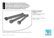
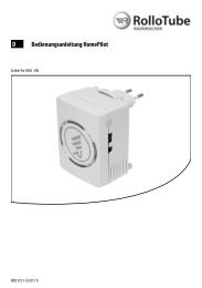
III. Packungsinhalt (Abb. 3)<br />
1. 1 Schlosskasten<br />
2. 1 Schließkasten<br />
3. 1 Schließblech<br />
4. 1 Anschraubleiste<br />
5. 2 Abdeckkappen Schlosskasten<br />
6. 1 Abdeckkappe Schließkasten<br />
7. 1 Satz Unterlagen je 1x1, 2, 4, 8 mm<br />
8. Schrauben:<br />
5 Stück 6,3 x 60 mm<br />
2 Stück 4,8 x 32 mm<br />
2 Stück 4,8 x 25 mm<br />
2 Stück M6 x 35 mm<br />
IV. Montagewerkzeug<br />
Kreuzschlitzschraubendreher<br />
Bohrmaschine<br />
Feile, Säge zum Kürzen der Schrauben, ggf. Schraubstock<br />
Bohrtabelle<br />
<strong>für</strong><br />
Schrauben<br />
Ø<br />
6,3 mm<br />
4,8 mm<br />
in Kunststoff<br />
ohne Metalleinlage<br />
Bohrer Ø<br />
4,5 mm<br />
3,5 mm<br />
in Alu <strong>und</strong> Kunststoff<br />
mit Metalleinlage<br />
Bohrer Ø<br />
5,0 mm<br />
3,5 mm<br />
G The instructions contain the following chapters:<br />
I. General Notes IV. Tools<br />
II. Applications V. Assembling Instructions<br />
III. Delivery Package VI. Operation<br />
I. General Notes<br />
The <strong>FTS</strong> 88 universal window lock is certified to meet the strict testing<br />
requirements of DIN 18104-1 and VdS 2536. The <strong>FTS</strong> 88 is certified<br />
to be “BURGLARY-RESISTANT DIN tested” by DIN Certco. Additionally,<br />
the <strong>FTS</strong> 88 provides protection against unauthorised access to your rooms.<br />
DIN 18104-1 recommends to install one additional lock on the left and right<br />
sides per metre of window height (per window). Police and insurance<br />
companies also recommend this.<br />
Optimal protection is provided if you follow these assembly and operating<br />
instructions. To prevent overturning, the fastening screws should be<br />
screwed in with a suitable tool and tightened by hand. Only use <strong>ABUS</strong><br />
fastening material.<br />
The manufacturer cannot be held liable for any injury or damage caused<br />
during assembly and/or by inexpert handling!<br />
It must be possible to open one access point to the entire object from the<br />
outside using a key.<br />
II. Applications<br />
The <strong>FTS</strong> 88 is mounted on the handle side of the window or French window<br />
and is suitable for all usual commercial windows/French windows opening<br />
to the inside with side/centre hung fittings (fig. 2).<br />
The locks can be installed on plastic or aluminium.<br />
The windows/French windows may open to the left or right side.<br />
The <strong>FTS</strong> 88 is as a rule mounted on the inside, the casing of the lock on the<br />
window wing and the lock case on the frame.<br />
Caution! To guarantee the function of the <strong>FTS</strong> 88, the positions of the casing<br />
of the lock and the lock case must not be mixed up.<br />
If the fastening is problematic, then several retention devices and additional<br />
means of fastening (fastening anchor or binding mortar) should be used.<br />
Please use the <strong>ABUS</strong> fastening anchor BA (plastic, aluminium windows)<br />
or the <strong>ABUS</strong> fastening set IM 100 (plastic windows).<br />
The IM 100 requires a suitable binding mortar e.g. Fischer FIS VS 150C,<br />
Hilti HFX or a similar product. <strong>ABUS</strong> BA and <strong>ABUS</strong> IM 100 and binding mortar<br />
are available from dealers.<br />
The additional <strong>ABUS</strong> products (FAS) shown in fig. 2 are also available<br />
from dealers.<br />
III. Delivery Package (fig. 3)<br />
1. 1 lock case<br />
2. 1 casing of the lock<br />
3. 1 striking plate<br />
4. 1 screw-on rail<br />
5. 2 covers for lock case<br />
6. 1 cover for casing of the lock<br />
7. 1 set of spacers 1x1 mm, 2 mm, 4 mm, 8 mm<br />
8. Screws:<br />
5 pieces 6.3 x 60 mm<br />
2 pieces 4.8 x 32 mm<br />
2 pieces 4.8 x 25 mm<br />
2 pieces M6 x 35 mm<br />
IV. Assembly Tools<br />
Cross-tip screwdriver<br />
Drilling machine<br />
File, saw for cutting screws to size, maybe vice<br />
Drilling table<br />
for<br />
screws<br />
Ø<br />
6.3 mm<br />
4.8 mm<br />
in PVC<br />
without metal insert<br />
drill bit Ø<br />
4.5 mm<br />
3.5 mm<br />
in aluminium and PVC<br />
with metal insert<br />
drill bit Ø<br />
5.0 mm<br />
3.5 mm
F Ce manuel comporte les chapitres suivants:<br />
I. Conseils d’ordre général IV. Outillage<br />
II. Application V. Instructions de montage<br />
III. Liste de colisage VI. Utilisation<br />
I. Conseils d’ordre général<br />
La serrure de fenêtre universelle <strong>FTS</strong> 88 satisfait aux exigences de contrôle<br />
sévères des normes DIN 18104-1et VdS 2536. Le certificat DIN indique<br />
que <strong>FTS</strong> 88 a obtenu la qualification «anti-effraction DIN».<br />
<strong>FTS</strong> 88 offre en plus une protection contre les intrusions par effraction<br />
dans votre logement. Selon la norme DIN 18104-1, il est recommandé<br />
de monter une sécurité complémentaire par mètre de hauteur de fenêtre,<br />
à gauche comme à droite (par fenêtre). La police et les compagnies<br />
d’assurance le recommandent également.<br />
Pour un effet de protection optimal, suivez les instructions de ce manuel<br />
d’installation et d’utilisation. Afin d’éviter un serrage abusif,<br />
vissez et serrez les vis de fixation à la main et avec un outillage adéquat.<br />
Utilisez exclusivement des accessoires <strong>ABUS</strong>.<br />
Le fabricant n’assume aucune responsabilité pour d’éventuels blessures<br />
ou dégâts causés pendant l’installation et/ou par suite de manipulations<br />
inappropriées!<br />
II. Application<br />
<strong>FTS</strong> 88 est monté du côté de la poignée de la fenêtre ou de la porte-fenêtre<br />
et convient pour toutes les fenêtres/portes-fenêtres courantes, ouvrant vers<br />
l’intérieur et pourvues de quincaillerie battante ou oscillo-battante (schéma 2).<br />
L’installation peut être effectuée sur des châssis en bois, en PVC ou en<br />
aluminium. Les fenêtres/portes-fenêtres peuvent s’ouvrir à gauche ou à droite.<br />
<strong>FTS</strong> 88 est monté en principe du côté intérieur, la gâche sur l’ouvrant et la<br />
serrure sur le dormant.<br />
Attention! Afin de garantir le bon fonctionnement de <strong>FTS</strong> 88, prenez garde<br />
à ne pas invertir la position du boîtier et de la gâche.<br />
En cas de possibilités de fixation défavorables (fenêtres en bois ou en PVC),<br />
plusieurs sécurités et des fixations supplémentaires (ancre de fixation)<br />
doivent être prévues.<br />
Pour cela, utilisez les ancres <strong>ABUS</strong> BA (pour fenêtres en PVC, en bois tendre ou<br />
en aluminium) ou l’ensemble de fixation <strong>ABUS</strong> IM 100 (pour fenêtres en PVC).<br />
Pour IM 100, un mortier approprié est requis, par exemple FIS VS 150C<br />
de la marque Fischer, HFX de la marque Hilti ou un produit similaire.<br />
<strong>ABUS</strong> BA et <strong>ABUS</strong> IM 100 ainsi que le mortier de fixation sont disponibles<br />
dans le commerce.<br />
Les produits <strong>ABUS</strong> complémentaires illustrés en schéma 2 (FAS) sont<br />
également disponibles dans le commerce.<br />
III. Liste de colisage (schéma 3)<br />
1. 1 boîtier<br />
2. 1 gâche<br />
3. 1 gâche en acier<br />
4. 1 socle de fixation<br />
5. 2 caches pour boîtier<br />
6. 1 cache pour gâche<br />
7. 1 ensemble d’entretoises chacun 1x1 mm, 2 mm, 4 mm, 8 mm<br />
8. Vis:<br />
5 pièces de 6,3 x 60 mm 2 pièces de 4,8 x 25 mm<br />
2 pièces de 4,8 x 32 mm 2 pièces M6 x 35 mm<br />
IV. Outillage<br />
Tournevis cruciforme<br />
Perceuse<br />
Lime, scie pour raccourcir les vis, tournevis<br />
Tableau de perçage<br />
pour<br />
vis<br />
de Ø<br />
6,3 mm<br />
4,8 mm<br />
dans châssis PVC<br />
sans armature métallique<br />
foret Ø<br />
4,5 mm<br />
3,5 mm<br />
F Instructions de montage et d’utilisation pour<br />
serrure de fenêtre universelle <strong>ABUS</strong> <strong>FTS</strong> 88<br />
n Montage- en gebruiksaanwijzing<br />
voor <strong>ABUS</strong> universeel bijzetslot <strong>FTS</strong> 88<br />
I Istruzioni di montaggio ed uso della<br />
serratura universale per finestre <strong>FTS</strong> 88<br />
dans châssis aluminium et PVC<br />
avec armature métallique<br />
foret Ø<br />
5,0 mm<br />
3,5 mm<br />
n Deze montage- en gebruiksaanwijzing is als volgt onderverdeeld:<br />
I. Algemeen IV. Gereedschap<br />
II. Toepassingsmogelijkheden V. Montage-instructies<br />
III. Verpakkingsinhoud VI. Gebruik<br />
I. Algemeen<br />
Bijzetgrendel voor naar binnen draaiende draai/kiep elementen.<br />
<strong>FTS</strong> 88 is volgens keuringseisen NEN 5096 SKG gecertificeerd.<br />
De <strong>FTS</strong> 88 biedt daarnaast bescherming tegen onbevoegd binnendringen<br />
van uw woning. Advies: monteer aan de sluitzijde voor maximale veiligheid<br />
2 stuks per 1 meter raamhoogte. Op kunststof zonder metalen kern dient<br />
u dit slot in combinatie met <strong>ABUS</strong> BA bevestigingsanker te monteren.<br />
Optioneel verkrijgbaar, zie voor montage in de handleiding van BA.<br />
Optimale veiligheid wordt bereikt door nauwkeurig opvolgen van deze<br />
montage- en gebruiksaanwijzing. Om overexpansie of doldraaien van de<br />
bevestigingsschroeven te vermijden, draait u handmatig en met passend<br />
gereedschap de schroeven vast.<br />
Voor eventueel verwondingen en/of schade tijdens montage en/of<br />
door ondesk<strong>und</strong>ig gebruik ontstaan, aanvaardt de fabrikant geen<br />
aansprakelijkheid!<br />
II. Toepassingsmogelijkheden<br />
De <strong>FTS</strong> 88 wordt aan de sluitzijde van het raam of deur gemonteerd en<br />
is geschikt voor alle gangbare naar binnen draaiende ramen en deuren<br />
met draai(/kiep)-beslag (afb. 2). De montage kan op de materialen hout,<br />
kunststof of aluminium worden uitgevoerd. De ramen/deuren kunnen naar<br />
rechts of links opengaan.<br />
<strong>FTS</strong> 88 wordt in principe uitsluitend aan de binnenkant gemonteerd;<br />
de slotkast op het raam of de deur en de sluitkast op het kozijn.<br />
Bij slechte bevestigingsmogelijkheden dienen meerdere beveiligingen<br />
en extra bevestigingsmaterialen te worden toegepast. Hiervoor kunt<br />
u het <strong>ABUS</strong>-bevestigingsanker BA (zacht hout, kunststof, aluminium)<br />
of de <strong>ABUS</strong>-bevestigingsset IM 100 (kunststof) gebruiken.<br />
Voor de IM 100 heeft u een geschikt chemisch anker, bijv. Fischer FIS VS 150C,<br />
Hilti HFX of vergelijkbaar nodig. <strong>ABUS</strong> BA, <strong>ABUS</strong> IM 100 en chemische ankers<br />
zijn in de handel verkrijgbaar.<br />
De in afb. 2 weergegeven <strong>ABUS</strong>-producten (FAS) zijn ook in de handel<br />
verkrijgbaar.<br />
III. Verpakkingsinhoud (afb. 3)<br />
1. 1 slotkast<br />
2. 1 sluitkast<br />
3. 1 sluitplaat<br />
4. 1 montageplaat<br />
5. 2 afdekkappen slotkast<br />
6. 1 afdekkap sluitkast<br />
7. 1 set opvulplaatjes 1x1 mm, 2 mm, 4 mm, 8 mm (elk 1stuk)<br />
8. Schroeven/bouten:<br />
5 stuks 6,3 x 60mm<br />
2 stuks 4,8 x 32mm<br />
2 stuks 4,8 x 25mm<br />
2 stuks M6 x 35mm<br />
IV. Gereedschap<br />
Kruiskopschroevendraaier<br />
Boormachine<br />
Vijl, zaag voor het inkorten van de schroeven, evt. bankschroef<br />
Boortabel<br />
voor<br />
schroeven<br />
Ø<br />
6,3 mm<br />
4,8 mm<br />
in kunststof<br />
zonder metalen kern<br />
boor Ø<br />
4,5 mm<br />
3,5 mm<br />
in aluminium en kunststof<br />
met metalen kern<br />
boor Ø<br />
5,0 mm<br />
3,5 mm<br />
classificatie manuele test<br />
zelfstandig<br />
I Queste istruzioni si suddividono in modo seguente:<br />
I. Istruzioni generali IV. Attrezzi<br />
II. Possibilità d’impiego V. Istruzioni di montaggio<br />
III. Contenuto della confezione VI. Uso<br />
I. Istruzioni generali<br />
La serratura universale per finestre è conforme ai severi requisiti<br />
di controllo della DIN 18104-1 e VdS 2536.<br />
Con la DIN Certco essa è certificata «ANTISCASSO conf. DIN».<br />
La <strong>FTS</strong> 88 garantisce una protezione in più a difesa della Vostra casa.<br />
Secondo DIN 18104-1 si consiglia di montare per ogni metro di<br />
altezza della finestra, due sicure supplementari sul lato della maniglia<br />
e una sicura di cerniere sul altro latosul lato.<br />
Anche la polizia e le compagnie d’assicurazione consigliano tali misure.<br />
Si può ottenere una protezione ottimale, procedendo secondo queste<br />
istruzioni di montaggio ed uso. Le viti di fissaggio, per evitarne un serraggio<br />
eccessivo, devono essere avvitate con un utensile adatto e poi serrate a mano.<br />
Impiegare esclusivamente materiale di fissaggio <strong>ABUS</strong>.<br />
Per eventuali ferimenti e/o danni, che si verificano durante il montaggio e/o<br />
per maneggio indebito, il produttore non si assume alcuna responsabilità.<br />
Un accesso a chiave deve essere garantito a ogni momento.<br />
II. Possibilità d’impiego<br />
La sicura <strong>FTS</strong> 88 va fissata al lato della maniglia della finestra/portafinestra<br />
ed è adatta per tutte le finestre e porte-finestre che si aprono verso l’interno,<br />
con ferramenti girevoli o girevoli a bilico (ill. 2). Si può montare la <strong>FTS</strong> 88 su<br />
plastica o alluminio. Le finestre o porte-finestre possono aprirsi verso destra<br />
o sinistra.<br />
Di solito la <strong>FTS</strong> 88 viene montata all’interno, il listello di chiusura sul battente<br />
e la cassa di serratura sul telaio.<br />
Attenzione! Per garantire il funzionamento della <strong>FTS</strong> 88, non scambiare<br />
le posizioni tra la cassa di serratura ed il listello di chiusura!<br />
Se le possibilità di fissaggio sono scadenti (sottofondo morbido, vuoto o<br />
riempito con espanso e finestre in plastica con o senza inserto metallico<br />
e finestre in legno) e le possibilità di effrazione dall’esterno sono buone,<br />
si dovrebbe utilizzare più sicure e mezzi di fissaggio supplementari<br />
(malta o avvitamento passante o bullone di fissaggio).<br />
Allo scopo utilizzare per favore il bullone di fissaggio <strong>ABUS</strong> BA o come<br />
alternativa nel caso di telai in plastica il kit di fissaggio <strong>ABUS</strong> IM 100.<br />
Per il IM 100 serve una malta adatta, p.e. della marca Fischer FIS VS 150C<br />
o un prodotto simile. <strong>ABUS</strong> BA e <strong>ABUS</strong> IM 100 come anche la malta si<br />
possono acquistare in commercio.<br />
I prodotti supplementari (FAS) nel ill. 2 sono ottenibili in commercio.<br />
III. Contenuto della confezione (ill. 3)<br />
1. 1 cassa di serratura<br />
2. 1 listello di chiusura<br />
3. 1 lamiera di chiusura<br />
4. 1 listello di montaggio<br />
5. 2 coperture cassa di serratura<br />
6. 1 copertura listello di chiusura<br />
7. 1 set di spessori da 1x1 mm, 2 mm, 4 mm, 8 mm<br />
8. Viti:<br />
5 da 6,3 x 60 mm<br />
2 da 4,8 x 32 mm<br />
2 da 4,8 x 25 mm<br />
2 M6 x 35 mm<br />
IV. Attrezzi<br />
cacciavite a croce<br />
trapano<br />
lima, sega per accorciare le viti, in caso morsa<br />
Tabella di trapanazioni<br />
per<br />
viti da<br />
Ø<br />
6,3 mm<br />
4,8 mm<br />
inbraakwerendheidsklasse<br />
NEN5096/ENV1630<br />
in plastica<br />
senza inserto metallico<br />
punta da trapano Ø<br />
4,5 mm<br />
3,5 mm<br />
contacttijd /<br />
gereedschapsset<br />
RC 2 3 min. / A<br />
zonder<br />
<strong>ABUS</strong> bevestigingsanker<br />
in alluminio e plastica<br />
con inserto metallico<br />
punta da trapano Ø<br />
5,0 mm<br />
3,5 mm<br />
gebruik BA-anker<br />
houten kozijnen kunststof kozijnen<br />
in combinatie met<br />
<strong>ABUS</strong> bevestigingsanker
Abb./fig.<br />
schéma<br />
afb./ill. 4a<br />
Abb./fig./schéma/afb./ill. 4b<br />
A<br />
Falzhöhe/Rebate height/Recouvrement/<br />
Opdekmaat/Altezza d’incassatura<br />
> 16 mm<br />
1<br />
2 mm<br />
4<br />
7<br />
Schlosskasten<br />
Lock case<br />
Boîtier<br />
Slotkast<br />
Casa<br />
7<br />
Rahmen<br />
Frame<br />
Cadre<br />
Kozijn<br />
Telaio<br />
Anschraubleiste<br />
Screw-on rail<br />
Socle de fixation<br />
Montageplaat<br />
Listello di montaggio<br />
2<br />
Tür/<strong>Fenster</strong><br />
Door/Window<br />
Fenêtre<br />
Deur/Raam<br />
Porta risp. Finestra<br />
<strong>ABUS</strong> - Das gute Gefühl der Sicherheit<br />
4<br />
Abb./fig./schéma/afb./ill. 5<br />
X mm<br />
Schließkasten<br />
Locking case<br />
Gâche<br />
Sluitkast<br />
Scatola<br />
D Technische Änderungen vorbehalten. Für Irrtümer <strong>und</strong> Druckfehler keine Haftung. <strong>ABUS</strong> © 2010<br />
G Subject to technical alterations. No liability for mistakes and printing errors. <strong>ABUS</strong> © 2010<br />
N<br />
N<br />
a<br />
b<br />
c<br />
d<br />
c<br />
b<br />
a<br />
1<br />
a<br />
a<br />
B<br />
Falzhöhe/Rebate height/<br />
Recouvrement/Opdekmaat/<br />
Altezza d’incassatura<br />
14 –16 mm<br />
2 mm<br />
D<br />
Falzhöhe/Rebate height/<br />
Recouvrement/Opdekmaat/<br />
Altezza d’incassatura<br />
1– 9 mm<br />
2 mm<br />
3<br />
2<br />
5<br />
6<br />
C<br />
Falzhöhe/Rebate height/<br />
Recouvrement/Opdekmaat/<br />
Altezza d’incassatura<br />
10 –13 mm<br />
2 mm<br />
E<br />
Falzhöhe/Rebate height/<br />
Recouvrement/Opdekmaat/<br />
Altezza d’incassatura<br />
0 mm<br />
2– 4 mm<br />
e<br />
f<br />
e<br />
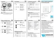
D V. Montageanleitung:<br />
Wichtige Hinweise:<br />
1. Vor der Montage prüfen Sie bitte die Einstellung des <strong>Fenster</strong>s bzw.<br />
der <strong>Fenster</strong>tür. Stellen Sie sicher, dass sich das <strong>Fenster</strong>/die <strong>Fenster</strong>tür<br />
einwandfrei öffnen <strong>und</strong> schließen lässt.<br />
2. Messen Sie auch nach, ob die in Abb. 1 angegebenen Mindestmaße<br />
an Ihrem <strong>Fenster</strong>/Ihrer <strong>Fenster</strong>tür vorhanden sind.<br />
3. Die Bohrlochtiefen bzw. die Schraubenlängen müssen auf die<br />
örtlichen Gegebenheiten abgestimmt werden.<br />
4. Austreten des Bohrers bzw. der Schrauben auf der Rückseite vermeiden!<br />
Ggf. mit Bohranschlag arbeiten oder die vorhandenen<br />
Schrauben kürzen. Beim Bohren keine beweglichen Teile, Dichtungen<br />
oder Glasscheiben verletzen.<br />
Montage:<br />
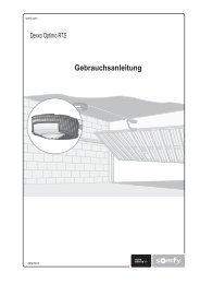
Montage des Schlosskastens (Abb. 4a + 4b)<br />
Falzhöhe ab 14 mm<br />
1. Abdeckplatten (5) des Schlosskastens (1) vorsichtig von unten ausstoßen.<br />
2. Anschraubleiste (4) in gewünschter Höhe 1 mm von der Türbzw.<br />
<strong>Fenster</strong>kante entfernt anhalten.<br />
3. Als Abstandshalter dünnste Unterlage (7) verwenden.<br />
Löcher „b“ (Abb. 4a) anzeichnen <strong>und</strong> vorbohren (s. Bohrtabelle).<br />
4. Anschraubleiste (4) ggf. mit Unterlagen (7) unterfüttern <strong>und</strong> mit Schrauben<br />
6,3 x 60 mm anschrauben, sodass sich die Fixiernocken „N“ (Abb. 4a)<br />
auf der zum <strong>Fenster</strong> abgewandten Seite befinden. Die Oberflächen der<br />
Anschraubleiste (4) <strong>und</strong> des <strong>Fenster</strong>flügels müssen auf einer Höhe liegen.<br />
5. Löcher „c“ durch die Anschraubleiste (4) hindurch schräg zum Mauerwerk<br />
hin bohren <strong>und</strong> Schrauben 6,3 x 60 mm eindrehen.<br />
6. Der eventuelle zusätzliche Einsatz von <strong>ABUS</strong> IM 100 oder <strong>ABUS</strong> BA erfolgt<br />
durch Loch „d“.<br />
7. Schlosskasten (1) mit Schrauben M6 x 35 mm auf der Anschraubleiste (4)<br />
befestigen.<br />
Falzstärke 1–13 mm<br />
1. Abdeckplatten (5) des Schlosskastens (1) vorsichtig von unten ausstoßen.<br />
2. Schlosskasten (1) in gewünschter Höhe 1 mm von der Tür- bzw. <strong>Fenster</strong>kante<br />
entfernt anhalten.<br />
3. Als Abstandshalter dünnste Unterlage (7) verwenden.<br />
4. Löcher „a“ anzeichnen <strong>und</strong> vorbohren (s. Bohrtabelle)<br />
(der eventuelle zusätzliche Einsatz von <strong>ABUS</strong> IM 100 oder <strong>ABUS</strong> BA erfolgt<br />
durch die Löcher „a“).<br />
5. Schlosskasten (1) mit Unterlagen (7) mit Schrauben 6,3 x 60 mm<br />
anschrauben.<br />
Falzstärke 0 mm (z.B. Schiebetür)<br />
1. Abdeckplatten (5) des Schlosskastens (1) vorsichtig von unten ausstoßen.<br />
2. Schlosskasten (1) mit dem Rahmen bündig abschließen lassen.<br />
3. Löcher „a“ anzeichnen <strong>und</strong> vorbohren (s. Bohrtabelle)<br />
(der eventuelle zusätzliche Einsatz von <strong>ABUS</strong> IM 100 oder <strong>ABUS</strong> BA erfolgt<br />
durch die Löcher „a“).<br />
4. Schlosskasten (1) mit Schrauben 6,3 x 60 mm anschrauben.<br />
Anmerkung: Bei Hebe-/Schiebetüren im abgesenkten Zustand<br />
2 Stück <strong>FTS</strong> 88 auf der Öffnungsseite montieren.<br />
Montage des Schließkastens (Abb. 5)<br />
1. Abdeckplatte (6) des Schließkastens (2) vorsichtig von unten durch die<br />
3 Löcher ausstoßen.<br />
2. Schließkasten (2) in gleicher Höhe des montierten Schlosskastens (1)<br />
im Abstand von 2 mm entfernt von diesem anhalten<br />
(bei Hebe-/Schiebetüren 2 bis max. 4 mm).<br />
Als Abstandshalter kann eine Unterlage (7) verwendet werden.<br />
3. Löcher „e“ anzeichnen <strong>und</strong> vorbohren (s. Bohrtabelle).<br />
4. Schließblech (3) gr<strong>und</strong>sätzlich in Schließkasten (2) einlegen (Abb. 4a).<br />
Schließkasten (2) mit Schrauben 4,8 x 25 oder 4,8 x 32 mm anschrauben.<br />
5. Loch „f“ durch den Schließkasten (2) hindurch schräg bohren <strong>und</strong><br />
Schraube 6,3 x 60 mm eindrehen.<br />
Funktion prüfen! Riegel müssen beim Einschließen in den Schließkasten<br />
<strong>und</strong> beim Heben <strong>und</strong> Senken der Hebe-Schiebetüren frei laufen.<br />
6. Abdeckungen (5 <strong>und</strong> 6) aufdrücken.<br />
VI. Bedienung<br />
<strong>FTS</strong> 88 wird mit dem Schlüssel ver- <strong>und</strong> entriegelt.<br />
G V. Assembling Instructions:<br />
Important notes:<br />
1. Prior to assembling, please check the adjustment of the window<br />
or French window. Make sure that the window/French window<br />
can be opened and closed correctly.<br />
2. Check that the min. dimensions shown in fig. 1 apply to your<br />
window or French window.<br />
3. The drill hole depths or screw lengths must be adjusted to local<br />
conditions.<br />
4. Avoid the drill bit or screws coming out on the rear sides!<br />
If necessary, use a bit stop or cut the screws to size.<br />
Do not damage any moving parts, seals or glass panes when drilling.<br />
Assembling:<br />
Assembling of the lock case (fig. 4a + 4b)<br />
Rebate > 14 mm<br />
1. Cautiously eject cover plates (5) of the lock case (1) from below.<br />
2. Hold screw-on rail (4) at desired height 1 mm away from door or window<br />
edge<br />
3. Use thinnest spacer (7) as spacer. Mark holes “b” (fig. 4a) and drill<br />
(see Drilling Table).<br />
4. Back screw-on rail (4) with spacers (7) if necessary and screw on using<br />
screws 6.3 x 60 mm. The surfaces of the screw-on rail (4) and the window<br />
wing must be flush.<br />
5. Drill holes “c” through the screw-on rail (4) at an angle with the masonry<br />
and screw in screws 6.3 x 60 mm.<br />
6. Possible additional use of <strong>ABUS</strong> IM 100 or <strong>ABUS</strong> BA through hole “d”.<br />
7. Fasten lock case (1) on the screw-on rail (4) with screws M6 x 35 mm.<br />
Rebate 1–13 mm<br />
1. Cautiously eject cover plates (5) of the lock case (1) from below.<br />
2. Hold lock case (1) at desired height 1 mm away from door or window<br />
edge.<br />
3. Use thinnest spacer (7) as guide plate to find the right distance.<br />
4. Mark holes “a” and drill (see Drilling Table).<br />
(Possible additional use of <strong>ABUS</strong> IM 100 or <strong>ABUS</strong> BA through holes “a”).<br />
5. Fasten lock case (1) with spacers (7) with screws 6.3 x 60 mm.<br />
Rebate 0 mm (e.g. sliding door)<br />
1. Cautiously eject cover plates (5) of the lock case (1) from below.<br />
2. Hold lock case (1) flush with frame.<br />
3. Mark holes “a” and drill (see Drilling Table) (Possible additional use<br />
of <strong>ABUS</strong> IM 100 or <strong>ABUS</strong> BA through hole “a”).<br />
4. Fasten lock case (1) with screws 6.3 x 60 mm.<br />
Note: For lifting/sliding doors, mount 2 x <strong>FTS</strong> 88 on the opening side<br />
in lowered condition.<br />
Assembling of the casing of the lock (fig. 5)<br />
1. Cautiously eject cover plate (6) of the casing of the lock (2) from below<br />
through the three holes.<br />
2. Hold casing of the lock (2) at height of the lock case mounted (1)<br />
at a distance of 2 mm from the lock case (2 to max. 4 mm for lifting/<br />
sliding doors). A spacer (7) can be used as spacer.<br />
3. Mark holes “e” and drill (see Drilling Table).<br />
4. Insert striking plate (3) into the casing of the lock (2) (fig. 4a).<br />
Fasten casing of the lock (2) with screws 4.8 x 25 or 4.8 x 32 mm.<br />
5. Drill hole “f” through casing of the lock (2) at an angle and screw in<br />
screw 63 x 60 mm.<br />
Check function! Bolts must run free when latching into the casing<br />
of the lock and when lifting or lowering the sliding door.<br />
6. Press on covers (5 and 6).<br />
VI. Operation<br />
The <strong>FTS</strong> 88 is locked/unlocked with the key.<br />
www.abus.com
F V. Instructions de montage:<br />
Indications importantes:<br />
1. Avant l’installation, contrôlez le réglage de la fenêtre ou de la porte-fenêtre.<br />
Assurez-vous que la fenêtre/porte-fenêtre ouvre et ferme parfaitement.<br />
2. Vérifiez si votre fenêtre/porte-fenêtre comporte les dimensions minimales<br />
indiquées en schéma 1.<br />
3. Les profondeurs de perçage ou les longueurs de vis doivent être adaptées aux<br />
conditions locales.<br />
4. Evitez le dépassement de perçage ou de vis sur la face arrière!<br />
Utilisez le cas échéant une butée de perçage ou raccourcissez les vis de fixation.<br />
5. Lors du perçage, évitez d’endommager les éléments mobiles,<br />
les joints ou les vitres.<br />
Montage:<br />
Montage du boîtier (schéma 4a + 4b)<br />
Recouvrement égal ou supérieur à 14 mm<br />
1. Décrochez avec précaution les caches (5) du boîtier (1) par le bas.<br />
2. Maintenez la socle de fixation (4) à la hauteur désirée et à 1 mm du bord<br />
de la fenêtre ou de la porte-fenêtre.<br />
3. Utilisez les entretoises les plus fines (7) pour l’espacement.<br />
Tracez et préforez les fixations de vis B (schéma 4a) (voir tableau de perçage).<br />
4. Fixez la socle de fixation (4) avec des vis de 6,3 x 60 mm et éventuellement des<br />
entretoises (7). La surface de la socle de fixation (4) doit se trouver à la même<br />
hauteur que la surface de l’ouvrant.<br />
5. Forez les trous de fixation ‘C’ de biais au travers de la socle de fixation (4)<br />
dans la maçonnerie et fixez-y les vis de 6,3 x 60 mm.<br />
6. Pour le montage éventuel d’<strong>ABUS</strong> IM 100 ou d’<strong>ABUS</strong> BA, utilisez les fixations de<br />
vis «D».<br />
7. Fixez le boîtier (1) sur la socle de fixation (4) avec des vis M6 x 35 mm.<br />
Recouvrement de 1–13 mm<br />
1. Décrochez avec précaution les caches (5) du boîtier (1) par le bas.<br />
2. Maintenez le boîtier (1) à la hauteur désirée et à 1 mm du bord de la fenêtre<br />
ou de la porte-fenêtre.<br />
3. Utilisez les entretoises les plus fines (7) pour l’espacement.<br />
4. Tracez et préforez les fixations de vis «A» (voir tableau de perçage)<br />
(pour le montage éventuel d’<strong>ABUS</strong> IM 100 ou d’<strong>ABUS</strong> BA, utilisez les fixations de<br />
vis «A»).<br />
5. Fixez le boîtier (1) avec des vis de 6,3 x 60 mm et des entretoises (7).<br />
Recouvrement de 0 mm (p. ex. porte coulissante)<br />
1. Décrochez avec précaution les caches (5) du boîtier (1) par le bas.<br />
2. Positionnez provisoirement le boîtier (1) sur l’encadrement de fenêtre.<br />
3. Tracez et préforez les fixations de vis «A» (voir tableau de perçage)<br />
(pour le montage éventuel d’<strong>ABUS</strong> IM 100 ou d’<strong>ABUS</strong> BA, utilisez les fixations de<br />
vis «A»).<br />
4. Fixez le boîtier (1) avec des vis de 6,3 x 60 mm.<br />
Remarque: Pour les portes coulissantes avec abaissement,<br />
installez 2 éléments <strong>FTS</strong> 88 en position abaissée, du côté ouverture.<br />
Montage de la gâche (schéma 5)<br />
1. Décrochez avec précaution les caches (6) du boîtier (1) par le bas,<br />
au travers des 3 trous.<br />
2. Maintenez la gâche (2) à la même hauteur que le boîtier installé (1),<br />
et à une distance de 2 mm de ce dernier (pour les portes coulissantes<br />
avec abaissement, de 2 à 4 mm). Utilisez éventuellement une entretoise (7)<br />
pour l’espacement.<br />
3. Tracez et préforez les fixations de vis «E» (voir tableau de perçage).<br />
4. Placez la gâche en acier (3) dans la gâche (2) (schéma 4a).<br />
Fixez la gâche (2) avec des vis de 4,8 x 25 ou 4,8 x 32 mm.<br />
5. Forez la fixation de vis «C» de biais au travers de la gâche (2) et fixez-y une vis<br />
de 6,3 x 60 mm.<br />
Contrôlez le bon fonctionnement! En position fermée, les pênes doivent être<br />
rétractés dans la gâche et doivent coulisser librement pendant le levage et<br />
l’abaissement des portes coulissantes.<br />
6. Clipsez les caches (5 et 6).<br />
VI. Utilisation<br />
<strong>FTS</strong> 88 est verrouillé/déverrouillé à l’aide d’une clé.<br />
n V. Montage-instructies:<br />
Belangrijke opmerkingen:<br />
1. Voor de montage dient u de afstelling van het raam resp. deur<br />
te controleren. Stel evt. het beslag opnieuw in, zodat het correct<br />
functioneert.<br />
2. Meet ook na, of de in afb. 1 aangegeven minimum afmetingen<br />
daadwerkelijk op uw raam/deur beschikbaar zijn.<br />
3. De boordieptes en schroeflengtes moeten aan het gevelelement<br />
aangepast worden.<br />
4. Voorkom doorboren en/of -schroeven. Evt. met een booraanslag<br />
werken, kortere schroeven kopen of inkorten. Bij het boren geen<br />
bewegende delen, afdichtingen of glas beschadigen.<br />
Montage van de slotkast (afb. 4a + 4b)<br />
Opdekmaat > 14mm<br />
1. De afdekkappen (5) van de slotkast (1) voorzichtig van onder af<br />
verwijderen.<br />
2. Montageplaat (4) op de gewenste hoogte op het raam of de deur<br />
plaatsen. Afstand t.o.v. de raam- resp. deurkant 1 mm.<br />
3. Als afstandhouder het dunste opvulplaatje (7) gebruiken.<br />
Boorgaten B (afb. 4a) aftekenen en voorboren (zie boortabel).<br />
4. Montageplaat (4) indien nodig met opvulplaatjes (7) uitvullen<br />
en m.b.v. de schroeven 6,3 x 60 mm monteren.<br />
Montageplaat en raam of deur moeten op dezelfde hoogte liggen.<br />
5. Boorgaten C door de montageplaat schuin richting muur voorboren<br />
en de schroeven 6,3 x 60 mm aanbrengen.<br />
6. Een eventuele aanvullende toepassing van <strong>ABUS</strong> IM 100 of <strong>ABUS</strong> BA<br />
geschiedt door boorgat D.<br />
7. De slotkast m.b.v. de bouten M6 x 35 mm op de montageplaat monteren.<br />
Opdekmaat 1–13 mm<br />
1. De afdekkappen (5) van de slotkast (1) voorzichtig van onder af<br />
verwijderen.<br />
2. Slotkast (1) op de gewenste hoogte op het raam of de deur plaatsen.<br />
Afstand t.o.v. de raam- resp. deurkant 1 mm.<br />
3. Als afstandhouder het dunste opvuplaatje (7) gebruiken.<br />
4. Boorgaten A aftekenen en voorboren (zie boortabel)<br />
(een eventuele aanvullende toepassing van <strong>ABUS</strong> IM 100 of <strong>ABUS</strong> BA<br />
geschiedt door boorgat A).<br />
5. De slotkast (1) incl. opvulplaatjes (7) m.b.v. de schroeven 6,3 x 60 mm<br />
monteren.<br />
Opdekmaat 0 mm (bijv. schuifdeuren)<br />
1. De afdekkappen (5) van de slotkast (1) voorzichtig van onder af<br />
verwijderen.<br />
2. Slotkast (1) met het kozijn krachtig laten vergrendelen.<br />
3. Boorgaten A aftekenen en voorboren (zie boortabel)<br />
(een eventuele aanvullende toepassing van <strong>ABUS</strong> IM 100 of <strong>ABUS</strong> BA<br />
geschiedt door boorgat A).<br />
4. De slotkast (1) m.b.v. de schroeven 6,3 x 60 mm monteren.<br />
Opmerking: Bij hef- en schuifdeuren in de laagste stand<br />
2 stuks <strong>FTS</strong>88 aan de sluitzijde monteren.<br />
Montage van de sluitkast (afb. 5)<br />
1. De afdekkap (6) van de sluitkast (2) voorzichtig van onder af door de<br />
3 gaten verwijderen.<br />
2. Plaats de sluitkast (2) op gelijke hoogte met de reeds gemonteerde<br />
slotkast (1) op 2 mm afstand tegen de raam of deur<br />
(bij hef-en schuifdeuren 2 tot max. 4 mm).<br />
Als afstandhouder kan een opvuplaatje (7) gebruikt worden.<br />
3. Boorgaten E aftekenen en voorboren (zie boortabel).<br />
4. Plaats de sluitplaat (3) in de sluitkast (2) (afb. 4a).<br />
Sluitkast m.b.v. de schroeven 4,8 x 25 mm of 4,8 x 32 mm monteren.<br />
5. Boorgat F schuin door de sluitkast (2) voorboren en de schroeven<br />
6,3 x 60 mm aanbrengen.<br />
Werking controleren: De schoten moeten bij het vergrendelen<br />
(ook bij hef-/schuifdeuren) vrij in de sluitplaat (2) lopen.<br />
6. Afdekkappen (5 en 6) op de sluitkast drukken.<br />
VI. Gebruik<br />
De <strong>FTS</strong> 88 wordt met een sleutel ver- en ontgrendeld.<br />
F Nous nous réservons le droit de toutes modifications techniques. Nous n’assumons aucune responsabilité pour des erreurs ou défauts d’impression éventuels. <strong>ABUS</strong> © 2010<br />
n Technische wijzigingen voorbehouden. Geen aansprakelijkheid voor vergissingen en drukfouten. <strong>ABUS</strong> © 2010<br />
I Ci si riservano modifiche tecniche. Per errori e refusi di stampa non ci si assume alcuna responsabilità. <strong>ABUS</strong> © 2010<br />
I V. Istruzioni per il montaggio:<br />
Avvertenze importanti:<br />
1. Prima del montaggio verificare per favore la regolazione della finestra<br />
risp. della porta-finestra. Se necessario registrare nuovamente i<br />
ferramenti affinché la finestra o la porta-finestra si chiuda e si apra<br />
perfettamente.<br />
2. Verificare anche che le misure minime indicate nell’ill. 1 che esistano<br />
nelle vostre finestre o porte-finestre.<br />
3. Le profondità per trapanare i fori, risp. Le lunghezze delle viti devono<br />
essere adatte alle condizioni particolari.<br />
4. Evitare che la punta del trapano risp. la vite fuoriesca dall’altra parte.<br />
Se necessario lavorare con arresto del trapano o accorciare le viti.<br />
5. Quando si trapana, non danneggiare parti mobili, guarnizioni o vetri.<br />
Montaggio:<br />
Montaggio della cassa di serratura (ill. 4a + 4b)<br />
Altezza d’incassatura a partire da 14 mm<br />
1. Le coperture (5) della cassa di serratura (1) vanno tolte spingendo<br />
dall’altra parte.<br />
2. Posizionare il listello di montaggio (4) in altezza desiderata spostata<br />
di 1 mm dal bordo della finestra.<br />
3. Come misura può essere usato lo spessore più sottile (7).<br />
Marcare i buchi «b» (ill. 4a) e forare seguendo la tabella di trapanazioni.<br />
4. Usare gli spessori (7) sotto il listello di montaggio (4) e fissare con le viti<br />
da 6,3 x 60 mm purché le superfici del listello (4) e del battente arrivino<br />
a stesso livello.<br />
5. Forare i buchi «c» attraverso il listello (4) diagonalmente al muro<br />
e fissare con le viti 6,3 x 60 mm.<br />
6. L’inserimento della malta <strong>ABUS</strong> IM 100 o l’ancora <strong>ABUS</strong> BA va inserito<br />
tramite il buco «d».<br />
7. Fissare la cassa di serratura (1) con le viti M6 x 35 mm sul listello<br />
di montaggio (4).<br />
Altezza d’incassatura da 1 mm a 13 mm<br />
1. Le coperture (5) della cassa di serratura (1) vanno tolte spingendo<br />
dall’altra parte.<br />
2. Posizionare il listello di montaggio (4) in altezza desiderata spostata<br />
di 1 mm dal bordo della finestra.<br />
3. Come misura può essere usato lo spessore più sottile (7).<br />
4. Marcare i buchi «a» e forarli secondo la tabella di trapanazioni.<br />
(L’inserimento della malta <strong>ABUS</strong> IM 100 o l’ancora <strong>ABUS</strong> BA va eseguito<br />
tramite il buco «a»).<br />
5. Fissare la cassa di serratura (1) con le viti M6 x 35 mm sul listello<br />
di montaggio (4).<br />
Altezza d’incassatura da 0 mm (p.es. finestra scorrevole)<br />
1. Le coperture (5) della cassa di serratura (1) vanno tolte spingendo<br />
dall’altra parte.<br />
2. Posare la cassa di serratura (1) al bordo del telaio.<br />
3. Marcare i buchi „a“ e forarli secondo la tabella di trapanazioni.<br />
(L’inserimento della malta <strong>ABUS</strong> IM 100 o l’ancora <strong>ABUS</strong> BA va eseguito<br />
tramite il buco «a»).<br />
4. Fissare la cassa di serratura (1) con le viti M6 x 35 mm sul listello<br />
di montaggio (4).<br />
Nota: Per le porte scorrevole montare in stato abbassato<br />
due pezzi <strong>FTS</strong> 88 alla parte dell’appertura.<br />
Montaggio del listello di chiusura (ill. 5)<br />
1. Spingere fuori il coperchio (6) del listello (2) dalla parte opposta.<br />
2. In stessa altezza come la cassa di serratura (1) posare il listello di chiusura<br />
(2) con uno spazio di 2 mm (per porte scorrevole 2 fino mass. 4 mm).<br />
Come misura usare un spessore (7).<br />
3. Marcare i buchi «e» e forare (guarda tabella di trapanazioni).<br />
4. La lamiera di chiusura (3) va inserita completamente<br />
nel listello di chiusura (2) (ill. 4a).<br />
Fissare il listello di chiusura con le viti 4,8 x 25 o 4,8 x 32 mm.<br />
5. Forare i buchi «f» attraverso il listello (2) diagonalmente e fissare con<br />
le viti 6,3 x 60 mm.<br />
Prova di funzionamento! I perni devono muoversi liberamente<br />
nel listello di chiusura anche dalle porte scorrevoli.<br />
6. Rimettere i coperchietti (5 e 6).<br />
VI. Uso<br />
La <strong>FTS</strong> 88 va aprita e richiusa solamente con la chiave.<br />
www.abus.com<br />
390037 12/10