ENCOUNTER AMPLIFIER MANUAL ENCOUNTER - Fusion
ENCOUNTER AMPLIFIER MANUAL ENCOUNTER - Fusion
ENCOUNTER AMPLIFIER MANUAL ENCOUNTER - Fusion

Create successful ePaper yourself
Turn your PDF publications into a flip-book with our unique Google optimized e-Paper software.
<strong>AMPLIFIER</strong> INSTALLATION<br />
INSTALLATION WARNINGS<br />
1. Ensure the +12V lead is disconnected from the battery before you connect any new<br />
equipment.<br />
2. Ensure that the amplifier mounting location and holes will not interfere with the gas tank,<br />
brake lines or electrical wiring.<br />
3. Ensure the amplifier is securely fastened to the vehicle to prevent the amplifier moving and<br />
causing damage in the event of an accident.<br />
4. Ensure all wiring is protected from sharp objects and from pinching or crushing which<br />
could result in damage to the audio system.<br />
5. Ensure the mounting location has sufficient air flow around the amplifier. If the amplifier is<br />
mounted in an enclosed space a 3” fan with ducting should be used to assist with cooling.<br />
6. Do not mount any amplifier on a subwoofer enclosure as extended exposure to vibration<br />
may cause damage to the amplifier.<br />
7. Ensure you use the minimum recommended gauge wire/cable or larger for all amplifier<br />
connections.<br />
8. Appropriate mounting is very important for prolonged life expectancy of any amplifier.<br />
Select a location that provides protection from moisture. Keep in mind that an amplifier<br />
should never be mounted upside down. Upside down mounting will compromise heat<br />
dissipation through the heat sink and could engage the thermal protection circuit.<br />
CONNECTION<br />
Ensure the audio system is turned off before making any connections to the amplifier,<br />
speakers or source unit. Failure to do so could result in permanent damage to the audio<br />
system.<br />
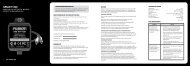
Ensure the correct gauge cable is used for all connections; consult the cable calculator<br />
diagram below for the correct gauge cable for your installation.<br />
TOTAL<br />
AMPS<br />
CABLE<br />
LENGTH<br />
><br />
M 0 - 1 1 - 2 2 - 3 3 - 4 4 - 5 5 - 6 6 - 7 7 - 9<br />
FT 0- 4 4 - 7 7 - 10 10 - 13 13 - 16 16 - 19 19 - 22 22 - 28<br />
0 - 20 14 12 12 10 10 8 8 8<br />
20 - 35 12 10 8 8 6 6 6 4<br />
35 - 50 10 8 8 6 4 4 4 4<br />
50 - 65 8 8 6 4 4 4 4 2<br />
65 - 85 6 6 4 4 2 2 2 0<br />
85 - 105 6 6 4 2 2 2 2 0<br />
105 - 125 4 4 4 2 0 0 0 0<br />
125 - 150 2 2 2 0 0 0 0 0<br />
The above chart shows cable gauges to be used, if no less than a 0.5 volt drop is acceptable.<br />
If aluminium wire is used, the gauges should be of an even larger size to compensate. Cable<br />
gauge size calculation takes into account terminal connection resistance.<br />
3