Coppia ruote Lefty.pub - FRM
Coppia ruote Lefty.pub - FRM
Coppia ruote Lefty.pub - FRM

Create successful ePaper yourself
Turn your PDF publications into a flip-book with our unique Google optimized e-Paper software.
<strong>FRM</strong><br />
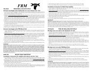
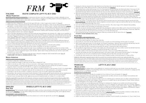
ITALIANO RUOTE COMPLETE LEFTY FL-M 21 DISC<br />
Mozzo Posteriore<br />
REGISTRAZIONE GIOCO CUSCINETTI: La registrazione del gioco viene fatta semplicemente avvitando o allentando con una<br />
chiave aperta il dado autobloccante di registrazione sul lato sinistro (3). Figura A. Un O-Ring interno lo friziona ed impedisce il suo<br />
allentamento. La registrazione può avvenire anche con la ruota montata sulla bici<br />
SMONTAGGIO E MANUTENZIONE<br />
1 Infilare due chiavi a brugola da 5 mm nei fori dei tappi dell’assale e svitare il tappo esterno sinistro (2). Figura B<br />
2 Mantenendo la chiave a brugola inserita nella sede del dado destro (lato ruota libera), svitare con una chiave aperta di dimensioni<br />
appropriate, a seconda del tipo di mozzo, il dado interno del lato sinistro (3). Sfilare l’assale (1) dal lato della ruota libera. Figura C<br />
3 La ruota libera (5) ruota su tre cuscinetti a sfere (5a-5c-5i). Controllare che i cuscinetti della ruota libera girino liberamente. Se si<br />
dovessero sostituire occorre svitare il bullone di fissaggio (5g) con una chiave a brugola da 10 mm. Stringere la parte lunga della<br />
chiave a brugola in una morsa. Tenendo la ruota orizzontale inserire il bullone della ruota libera nella parte corta della chiave e<br />
svitarlo girando la ruota in senso antiorario. Figura D<br />
4 Con la ruota libera appoggiata sui bordi di una morsa tenuta più larga del diametro del cuscinetto (5i), colpire con un martelletto la<br />
chiave a brugola inserita nel bullone di fissaggio (5g) in modo che il bullone ed il cuscinetto (5i) escano dalla parte posteriore della<br />
ruota libera. Figura E. Sostituire i cuscinetti, pulire bene tutti gli interni e lubrificare i martelletti con alcune gocce di olio denso da<br />
catena. Figura F. Reinserire il bullone ed il cuscinetto nella loro sede, ruotando la ruota libera in senso antiorario per ingaggiare i<br />
martelletti. Controllare che i martelletti si innestino quando la ruota libera viene ruotata in senso orario.<br />
5 Posizionare la rondella in acciaio (7) interponendola tra corpo mozzo e ruota libera ed avvitare il bullone della ruota libera sul<br />
mozzo. Quando la ruota libera inizia ad entrare nell’incavo del corpo mozzo fare attenzione che la lamella in gomma (5e) che si<br />
trova sul bordo della ruota libera entri liberamente nel corpo mozzo senza piegarsi<br />
6 Serrare con forza il bullone di fissaggio del corpo cassetta. Il serraggio definitivo avverrà alle prime pedalate<br />
7 Controllare le condizioni del cuscinetto (5a) sul lato sinistro. Sostituirlo con uno nuovo se necessario.<br />
8 Infilare l’assale nella ruota libera e quindi nel corpo mozzo controllando lo stato della lamella in gomma (4). Avvitare il dado<br />
interno (3) del lato sinistro sull’assale fino a fondo, quindi svitarlo di 1/8 di giro. Controllare che l’assale giri liberamente e che non<br />
ci siano giochi. Nel caso riaggiustare il gioco creato dal dado. Questo dado è di tipo autobloccante per cui non si sposta dalla<br />
posizione in cui viene avvitato<br />
9 Avvitare il tappo sinistro (2) e bloccarlo usando due chiavi a brugola contrapposte sulle estremità dell’assale. Figura B<br />
STRINGERE CON MOLTA MODERAZIONE (2 Nm)<br />
Mozzo Anteriore<br />
SMONTAGGIO E MANUTENZIONE<br />
1 Smontare il caliper disco anteriore dalla forcella <strong>Lefty</strong><br />
2 Svitare il bullone di fissaggio (5) alla ruota con una chiave a brugola da 5 mm<br />
3 Sfilare la ruota dal suo assale. Tirare con forza se necessario, o dare leggeri colpetti alla flangia interna del mozzo<br />
4 Con un perno metallico o in plastica dura del diametro da 16 a 18 mm, infilato nel mozzo dal lato del cuscinetto di diametro<br />
maggiore, estrarre il cuscinetto 24x15x5 2RS (4), e a seguito al sua rondella spaziatrice (2)<br />
5 Con una piccola pinza a becchi o un cacciavite sottile smontare la molla di ritenzione (7) del cuscinetto 37x25x7 (3) a doppio labbro<br />
6 Estrarre questo cuscinetto (3) colpendolo dalla sede del cuscinetto piccolo con il precedente perno, procedendo in rotazione<br />
7 Controllare lo stato dei due cuscinetti e sostituirli se necessario. Usare solo ricambi originali forniti dalla <strong>FRM</strong><br />
8 Riassemblare i due cuscinetti e posizionare la molla ritenzione (7) del cuscinetto grande facendo attenzione che sia completamente<br />
inserita nella sua sede. Aiutarsi con un piccolo cacciavite comprimendola nella sede. Verificare che non esca facilmente<br />
9 Inserire il mozzo nel perno della forcella, applicare una goccia di frenafiletti medio sul bullone (5) e avvitarlo a 8Nm<br />
GARANZIA: I prodotti <strong>FRM</strong> sono garantiti contro difetti di materiale e costruzione per un periodo di 2 anni dalla data di acquisto del primo utilizzatore, certificata dallo<br />
scontrino fiscale del negozio. La garanzia decade nel caso in cui la manutenzione ordinaria o straordinaria consigliata in questo manuale non sia stata eseguita OBBLIGHI: in caso di<br />
vizio, <strong>FRM</strong> si impegna ad effettuare la sostituzione o la riparazione, a sua discrezione dell’elemento riconosciuto difettoso. Per essere accettato, il difetto deve essere comunicato dal<br />
legittimo proprietario al negoziante dove il prodotto è stato acquistato e da quest’ultimo, dopo averlo verificato, alla <strong>FRM</strong> Nel caso in cui la <strong>FRM</strong> non riconosca l’esistenza del difetto o<br />
stabilisca che questo è dovuto ad una delle cause riportate nel seguente paragrafo, la sostituzione non è dovuta ed il componente viene restituito a spese del destinatario. LIMITI: la garanzia<br />
non copre i danni risultanti da trasporto, giacenza, incidenti, negligenze, colpi o cadute, mancato rispetto delle informazioni del libretto istruzioni, montaggio errato o con prodotti non<br />
compatibili, cattiva manutenzione, usura normale, modifiche o alterazioni del prodotto. La Garanzia non copre le parti soggette a normale usura (cuscinetti, paraolio ecc.)<br />
———————————————————————————————————————————————————————————————<br />
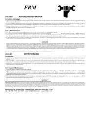
ENGLISH WHEELS LEFTY FL-M 21 DISC<br />
Rear Hub<br />
BEARING PLAY: The bearing play should be adjusted by simply screwing or unscrewing the self-locking nut of the left side (3) with<br />
an open wrench. Drawing A. An inner rubber O-Ring frictions the nut and avoids its unwanted turning. Play can be adjusted without<br />
disassembling the wheel from the bike.<br />
DISASSEMBLY AND MAINTENANCE<br />
1 Using two opposed 5 mm Allen keys, unscrew the external nut (2) on the side opposite the cassette body. Drawing B<br />
2 Keeping the Allen key inserted in the right sided lock-nut (freewheel side), unscrew the left inner nut (3) with a spanner (size<br />
depends on type of hub). Remove the axle (1) from the freewheel side. Drawing C<br />
3 The freewheel turns on three ball bearings (5a-5c-5i). Check that the freewheel bearings turn freely and replace if necessary. In this<br />
case the fixing bolt (5g) must be unscrewed using a 10 mm Allen key. Clamp the long arm of the Allen key into a vice. With the<br />
wheel held horizontal, slide the freewheel bolt into the short arm of the Allen Key and turn the wheel counterclockwise. Drawing D<br />
4 With the freewheel balanced on the edges of a vice opened wider than the diameter of the bearing (5i), use a small hammer to hit the<br />
Allen key inserted into the fixing bolt (5g) so that the bolt and the bearing come out of the rear part of the freewheel body. Drawing<br />
E. Replace the bearings cleaning well all inner parts and lubricate the lips of the fixing bolt with a few drops of dense chain oil.<br />
Drawing F. Re-insert the fixing bolt and the bearing, turning the freewheel body anti-clockwise to engage the lips. Check that the lips<br />
(5h) slot into place when the freewheel is rotated clockwise.<br />
5 Put the steel washer (7) into place between the hub body and the freewheel and screw the freewheel fixing bolt into the hub body.<br />
Only for MTB hubs: when the freewheel is almost completely screwed in check to make sure that the rubber lip (5e) of the freewheel<br />
body is not caught between the edge of the recess.<br />
6 Screw the freewheel fixing bolt into the freewheel and close with force. The correct torque will be obtained when pedalling<br />
7 Check the condition of the left bearing (5a) and replace if necessary.<br />
8 Insert the axle into the freewheel and through the hub-body checking the condition of the rubber seal (4). Screw the left inner nut (3)<br />
all the way onto the axle and then unscrew it 1/8 of a turn. Check that the axle turns freely and without play. If necessary, adjust the<br />
play created by the nut. This nut will not loosen in time as it is of the self-locking type.<br />
9 Screw on the left lock-nut (2) and block by using two Allen keys inserted into the two ends of the axle. Drawing B<br />
TIGHTEN WITH MODERATION (2Nm)<br />
Front Hub<br />
DISASSEMBLY AND MAINTENANCE<br />
1 Disassemble the disc caliper from the <strong>Lefty</strong> fork<br />
2 Unscrew the wheel fixing bolt (5) with a 5 mm Allen Key<br />
3 Disassemble the wheel from the fork. Pull hard if necessary or tap the rear of the hub flange with the palm of your hand<br />
4 With a small mallet tap the end of a 16-18 mm dia. rod of metal or hard plastic, which has been inserted into the hub body form the<br />
side of the larger bearing, until the 24x25x5 2RS bearing (4) is taken out. Extract the light alloy washer (2)<br />
5 With a tiny Small Tip Plier or Screwdriver disassemble the spring (7) retaining the larger bearing in place<br />
6 Disassemble the larger bearing (3) 37x25x7 with double seals (red) utilising the same rod as before, inserted into the hub body from<br />
the side of the smaller bearing. Tap gently all around the bearing until it comes away<br />
7 Check the condition of the bearings and replace them if necessary. Always use original <strong>FRM</strong> replacements<br />
8 Assemble the bearings into their seats tapping them gently with a plastic mallet, and mount the retaining spring (7) of the bigger<br />
bearing into its seat. Use a tiny screwdriver to press it into place. Be sure that it does not come out too easily<br />
9 Assemble the wheel onto the axle of the fork, put one drop of Medium Locktite on the bolt threads (5). Torque at 8Nm<br />
WARRANTY: <strong>FRM</strong> products are guaranteed against any defects for a period of 2 years from the date of purchase by the first owner, registered in a dealer shop.<br />
OBLIGATIONS: In case of defects, <strong>FRM</strong> pledge to replace or repair, at their discretion, the part recognised as defective. To be accepted, the rider compliant must be communicated to <strong>FRM</strong><br />
through the dealer/importer after his own control. If <strong>FRM</strong> after sales checking reveals that the damage is due to one of the reasons mentioned in the following paragraph, the replacement is no<br />
longer accepted and the defective item is sent back to the plaintiff who supports the shipping fees. LIMITATIONS: The guarantee does not cover damage resulting from transportation,<br />
warehousing, accidents, negligence, impact or falls, non-compliance with the information in the instruction manuals, assembly errors, assembly using non-compatible products, bad<br />
maintenance, modifications or alterations to the product. The guarantee does not cover parts and components subject to normal wear and tear such as ball-bearings, bushings, seals, etc.<br />
——————————————————————————————————————————————————————————————–<br />
FRANCAIS LEFTY FL-M 21 DISC<br />
Moyeu arrière<br />
REGLAGE DU JEU: Le réglage du jeu se fait simplement en vissant ou en dévissant avec une clé plate l’écrou auto-bloccant de<br />
réglage côté gauche (3). Figure A. Un joint O-Ring interne crée un frottement qui empêche l’écrou de se désserrer. Le réglage peut être<br />
fait également avec la roue montée sur le vélo.<br />
DEMONTAGE ET ENTRETIEN<br />
1 Enfiler deux clé 6 pans de 5 mm dans les extrémités de l’axe et dévisser l’écrou côté gauche (2). Figure B<br />
2 Tout en maintenant la clé 6 pans insérée dans l’axe côté droit (côté roue libre), dévisser avec une clé plate l’écrou intérieur côté<br />
gauche (3). Retirer l’axe (1) du côté roue libre. Figure C<br />
3 La roue libre (7) tourne sur trois roulements à billes (5a-5c-5i). Contrôler que les roulements de la roue libre tournent librement. Si<br />
des roulements de la roue libre sont à changer, il faut dévisser la vis centrale (5g) avec une clé 6 pans de 10 mm. Utiliser au besoin<br />
un tube prolongateur car le serrage est élevé. Figure D<br />
4 Poser la roue libre sur un étau légerement plus ouvert que le roulement (5i), et taper avec un maillet sur la clé 6 pans de 10mm<br />
toujours insérée dans la vis de fixation (5g). De cette façon, la vis et le roulement (5i) sortent par l’arrière de la roue libre. Figure E.<br />
Remplacer les roulements, tout bien nettoyer et lubrifier les cliquets avec quelques gouttes d’huile épaisse. Figure F. Remettre la vis<br />
de fixation et les roulements à leur place. Faire tourner la roue libre dans le sens anti-horaire pour engager correctement les cliquets.<br />
Contrôler que les cliquets s’engagent correctement quand la roue libre tourne dans le sens horaire.<br />
5 Positionner la rondelle en acier (7) entre le corps de moyeu et la roue libre.<br />
6 Revisser et resserrer la vis de fixation de la roue libre. Pour les moyeux de VTT : quand la roue libre commence à rentrer dans son<br />
logement, faire attention que le joint qui se trouve au bord prenne bien sa place et ne soit pas écrasé.<br />
7 Contrôler l’état du roulement (5a) côté gauche. Le remplacer si nécessaire.<br />
8 Enfiler l’axe dans la roue libre et dans le corps du moyeu en contrôlant l’état de la lamelle en cahoutchouc (4). Visser à fond l’écrou
intérieur (3) sur l’axe côté gauche, puis le dévisser d’un huitième de tour. Contrôler que l’axe tourne librement et sans jeu. Au besoin<br />
réajuster le jeu. L’écrou auto-bloccant gardera sa position.<br />
9 Visser l’écrou gauche (2) et le bloquer en utilisant une clé 6 pans à chaque extrémité de l’axe. Figure B<br />
SERRER MODEREMENT (2Nm)<br />
Moyeu Avant<br />
DEMONTAGE ET ENTRETIEN<br />
1 Dévisser le boulon de fixation (5) de la roue avec une clé 6 pans de 5 mm<br />
2 Sortir la roue de son axe. Tirer avec force si nécessaire, ou taper légèrement sur la flasque intérieure du moyeu<br />
3 Avec une pièce allongée en métal ou en plastique de 16 à 18mm de diamètre enfilée dans le moyeu du côté du roulement le plus<br />
gros, chasser le roulement 24x15x5 2RS (4) et sa rondelle entretoise (2)<br />
4 Avec une petite pince à bec ou avec un tourne vis fin, démonter le ressort (7) du roulement 37x25x7 (3)<br />
5 Extraire ce roulement (3) par l’intérieur du moyeu en utilisant la même pièce que précédemment. Procéder lentement et en tournant.<br />
6 Contrôler l’état des roulements et les remplacer si nécessaire. Utiliser uniquement les pièces de rechange fournies par <strong>FRM</strong><br />
7 Remonter les roulements et positionner le ressort (7) du gros roulement en veillant à ce qu’il soit bien positionné dans son logement.<br />
Utiliser un petit tourne vis pour le comprimer à sa place. Vérifier qu’il ne sorte pas tout seul.<br />
8 Insérer le moyeu sur l’axe de la fourche, mettre une goutte de frein filet moyen sur l’écrou (5) et serrer à 8Nm<br />
GARANTIE: Les produits <strong>FRM</strong> sont garantis contre tout défaut matériel et de construction pour une période de 2 ans à partir de la date d’acquisition par le premier utilisateur,<br />
certifiée par la facture établie par un détaillant. La garantie échoit dans le cas où l’entretien ordinaire ou extraordinaire conseillé dans cette notice n’ait pas été suivi. OBLIGATIONS : en<br />
cas de vice, <strong>FRM</strong> s’engage à effectuer à sa discrétion le remplacement ou la réparation de l’élément reconnu défectueux. Pour être accepté, le défaut doit être communiqué par le propriétaire<br />
légitime au commerçant chez qui le produit a été acheté et, du détaillant à <strong>FRM</strong>, après vérification du caractère défectueux de la marchandise. Dans le cas où <strong>FRM</strong> ne reconnaîtrait pas<br />
l’existence du défaut ou établirait qu’il est dû à l’une des causes énoncées dans le paragraphe suivant, le remplacement ne serait pas effectué et le composant serait restitué aux frais du<br />
destinataire. LIMITES : la garantie ne couvre pas les dommages causés lors du transport ni les dommages causés par un problème de stockage, par un accident, une négligence, un coup ou<br />
une chute, un manque de suivi des informations de la notice d’instruction, un montage erroné ou un montage avec des pièces non compatibles, un mauvais entretien, une usure normale, des<br />
modifications ou une altération du produit. La garantie ne couvre pas les parties soumises à une usure normale (roulements, joints, etc.).<br />
——————————————————————————————————————————————————————————————<br />
DEUTSCH LEFTY FL-M21 DISC<br />
Hinterrad-Nabe<br />
LAGERSPIEL: Das Lagerspiel kann auf einfache Weise durch Justage der Einstellmutter (3) auf der rechten Seite durchgeführt werden<br />
Grafik A. Verwenden Sie dazu einen flachen Maulschlüssel (je nach Achsentyp unterschiedlich). Der Gummi-Ring innen in der Mutter<br />
sorgt durch seinen Reibungswiderstand dafür, dass sich die Einstellmutter nicht von alleine verstellt. Sie können dass Lagerspiel somit<br />
ohne Ausbau des Laufrades durchführen. ACHTUNG: Bei Fett auf der Achse kann sich die Einstellmutter eventuell von alleine<br />
verstellen. Drehen gehen den Uhrzeigersinn macht das Lagerspiel weiter, mit dem Uhrzeigersinn fester.<br />
WARTUNG UND MONTAGE<br />
1 Das Zerlegen der Achse erfolgt lediglich über zwei M5-er Imbus-Schüssel gegen den Uhrzeigersinn. Dadurch löst sich die äußere<br />
Mutter (2) auf der linken Naben-Seite. Grafik B<br />
2 Zum entfernen der Einstellmutter (3) halten Sie den Imbus-Schlüssel weiter auf der Freilaufseite in der Achse und drehen diese<br />
gegen den Uhrzeigersinn herunter. Danach können Sie die Achse herausziehen. Grafik C<br />
3 Der Freilauf bewegt auf drei Lagern (5a-5c-5i). Überprüfen Sie die Lager und stellen Sie sicher, dass problemlos laufen. Sämtliche<br />
Lager sind bei <strong>FRM</strong> Deutschland erhältlich. Zum Austausch von Lagern sollten Sie den Freilauf herausdrehen. Dazu benötigen Sie<br />
einen M10-Imbus-Schüssel. Der Austausch empfiehlt sich nur in eingespeichtem Zustand. Klemmen Sie den M10-Imbus-Schüssel<br />
in einen Schraubstock, setzen Sie den Freilauf, bzw. Sperrklinken-Bolzen des Freilauf auf den Imbus-Schlüssel und drehen Sie das<br />
Rad gegen den Uhrzeigersinn. Der Freilauf-Bolzen, auf dem die Sperrklinken mit dem Freilauf-Körper sitzen, läßt sich so aus dem<br />
Naben-Körper herausdrehen. Grafik D<br />
4 Nach Trennen von Freilaufkörper und Sperrklinkenbolzen ist jedes Lager erreichbar Grafik E Verwenden Sie ausschließlich Öl für<br />
die Sperrklinken, am besten Wet-Lubricant (bsw. Wasserbeständiges Kettenöl). Verwenden Sie ausschließlich Fett für die Lager. Die<br />
Lager sitzen in der Regel sehr fest im Freilaufkörper. Sie können mit einem Stösel und wechselseitigen leichten Schlägen aus dem<br />
Freilaufkörper (Free– Hub Body) herausgetrieben werden Grafik F. Nach dem Reinigungvorgang und dem Zusammenstecken von<br />
Freilauf-Bolzen und Freilauf-Körper sollten die Sperrklinken leicht einschnappen.<br />
5 Die ganze Freilaufeinheit im Uhrzeigersinn wieder in den Naben-Körper eindrehen und mit (35-45 Nm) anziehen. Fall er über eine<br />
Dichtung (Gummi-Lippe) verfügt, bitte sicherstellen, dass diese gefettet ist und nicht verkanntet.<br />
6 Beim erneuten Einstecken der Achse ebenfalls sicherstellen, dass die Dichtung (Gummi-Lippe) nicht verkanntet und gut gefettet ist.<br />
Nach Einstecken die Einstellmutter (3) wieder auf die Achse schrauben (Mutter mit Maulschlüssel, Achse mit Imbus-Schlüssel<br />
kontern). Nachdem die Einstellschraube angezogen ist, drehen Sie diese wieder1/8 Drehung zurück.. Stellen Sie sicher, dass sich die<br />
Achse jetzt frei drehen läßt. Bei Bedarf Achsspiel nochmals korrigieren, am besten bei eingebautem Laufrad.<br />
7 Schrauben Sie die äußere Mutter wieder auf. BEI KARBON-ACHSEN MIT ÄUERSTER VORSICHT (2 Nm)<br />
Front Hub<br />
Gewährleistung: <strong>FRM</strong> Produkte besitzen eine Gewährleistung von zwei Jahren mit Beginn des Kaufdatum gegen Versagen, Defekte oder Bruch. Es zählt das Datum des Erwerbs<br />
bei einem registrierten Fachhändler. VERPFLICHTUNG: Im Falle von Versagen oder Defekten verpflichtet sich <strong>FRM</strong> nach eigenem Ermessen die als fehlerhaft erkannten Teile<br />
auszutauschen oder zu reparieren. Die Verpflichtung wird erst dann wirksam, nachdem der Besitzer des defekten Gegenstands durch einen Händler oder Importeur als solcher überprüft und<br />
ausgewiesen wurde und der entsprechende Gegenstand durch den Händler oder Importeur an <strong>FRM</strong> weitergeleitet wurde. Falls die Überprüfung durch <strong>FRM</strong> ergibt, dass der Defekt oder das<br />
Versagen durch einen im Nachfolgenden Absatz genannten Gründe zustande gekommen ist, ist ein Ersatz ausgeschlossen und das defekte Teil wird aus Kosten desjenigen zurückgesendet,<br />
der das Teil an <strong>FRM</strong> gesendet hat. AUSSCHLUSS: Die Gewährleistung deckt keine Schäden ab, die durch Transport, Lagerung, Unfälle, Fahrlässigkeit, äußere Einwirkung, Sturz zustande<br />
gekommen oder durch die Nichtbeachtung der Anweisungen in den Instruktions- und Anweisungsunterlagen zurückzuführen sind. Sie deckt auch kein Fehlverhalten beim Zusammenbau, der<br />
Verwendung nicht-kompatibler Komponenten oder Fremdkomponenten, oder falsche Wartung ab und wird hinfällig durch Modifizierung oder Änderungen am Produkt. Die Gewährleistung<br />
deckt nicht Teile und Komponenten ab, die Gegenstand von regelmäßigem Verschleiß sind wie Kugellager, Dichtungen, etc.<br />
Allentare<br />
Loosen<br />
(D)<br />
8<br />
5i<br />
2<br />
5g<br />
3<br />
5h<br />
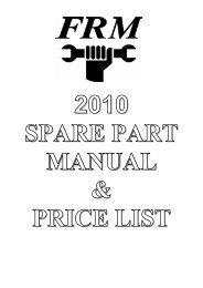
Gioco cuscinetti<br />
Bearing play<br />
Stringere<br />
Tighten<br />
Svitare<br />
Unscrew<br />
9<br />
4<br />
5f<br />
(A)<br />
Brugola da 10 mm<br />
10 mm Allen Key<br />
ESPLOSO<br />
SCHEMATIC VIEW<br />
5e<br />
7<br />
Montaggio<br />
Assemble<br />
Max 2Nm<br />
1<br />
5d<br />
Distributed by: The Bike Shop Via Mattei 18/A 48025 Riolo Terme (Ra) ITALY<br />
Ph +39 0546 70310 Fax 74623 e-mail: info@frmbike.com www.frmbike.com<br />
5c<br />
(B)<br />
5<br />
5b<br />
Smontaggio<br />
Disassemble<br />
Battere sulla chiave a brugola per estrarre<br />
il bullone di fissaggio<br />
Hammer the Allen Key to disassemble the<br />
fixing bolt<br />
7<br />
(E)<br />
3<br />
5a<br />
4<br />
6<br />
Svitare<br />
Unscrew<br />
1<br />
(C)<br />
Estrarre<br />
Pull-out<br />
Estrarre i cuscinetti prima con una spina<br />
da 14 mm, poi con una da 17 mm<br />
Push the bearings out of their seats,<br />
first with a rod of dia. 14 mm,<br />
then with one of dia. 17<br />
mm<br />
(F)<br />
2<br />
4<br />
5<br />
6