
You also want an ePaper? Increase the reach of your titles
YUMPU automatically turns print PDFs into web optimized ePapers that Google loves.
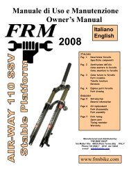
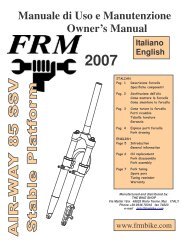
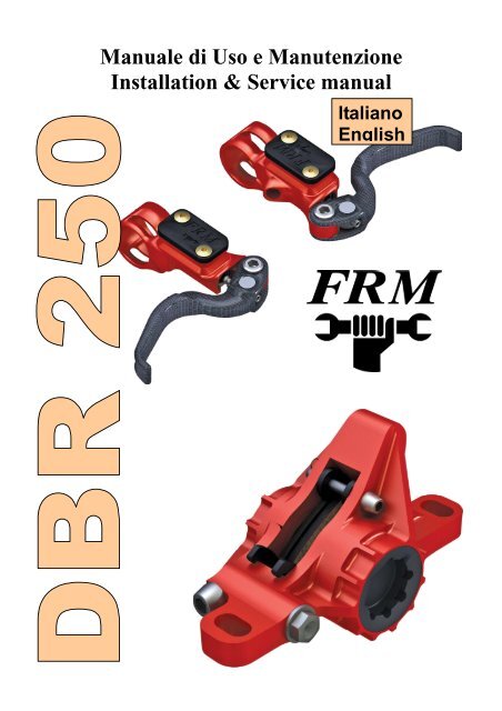
Manuale di Uso e Manutenzione<br />
Installation & Service manual<br />
Italiano<br />
English
Congratulazioni per aver scelto i freni <strong>FRM</strong> DBR. E’ necessario leggere questo manuale prima di usarli<br />
Identificazione <strong>Freni</strong><br />
• Questo manuale riguarda il modello DBR 250.<br />
• I <strong>DBR250</strong> sono dotati di bulloneria in titanio per il fissaggio sia delle pinze che dei dischi, in Ergal per il<br />
fissaggio della pompa, tubazione idraulica FrenTubo Carbotech rinforzata in Carbonio, pastiglie freno<br />
Organiche su supporto in alluminio e dischi in acciaio Sawrotor II a scelta nei diametri 160mm ant., 140mm<br />
post. e 160mm ant. / post.<br />
Avvertenze e Norme di Sicurezza<br />
• I freni <strong>FRM</strong> DBR devono essere istallati da un meccanico professionista che utilizzi la attrezzatura idonea.<br />
Ignorando questa importante avvertenza, è necessario seguire scrupolosamente le istruzioni del manuale,<br />
tenendo presente che lo si fa comunque a proprio esclusivo rischio e pericolo<br />
• AVVERTENZA: Per il montaggio dei freni a disco è indispensabile l’utilizzo di una chiave dinamometrica<br />
• Verificare con frequenza i serraggi delle viti delle pinze e dischi, come da dati riportati sul presente manuale.<br />
• Il telaio e la forcella della MTB devono essere predisposti per il montaggio dei freni a disco, con supporti di<br />
tipo International Std. o Post-Mount. I mozzi ruota devono supportare il fissaggio International Std a 6 fori.<br />
Non tentare di montare impianti frenanti su forcelle e/o telai non predisposti, allestendo adattatori artigianali<br />
• Prendere dimestichezza con la frenata su una superficie piana prima di intraprendere una discesa impegnativa<br />
• Prima di partire per una uscita in bici verificare su una superficie piana che ambedue i freni funzionino<br />
• Azionando i freni, i dischi si riscaldano considerevolmente; non toccare i dischi appena scesi di sella<br />
• In caso di bagnato la frenata tende a ridursi; calcolare il maggior spazio di frenata in caso di pioggia e<br />
applicare una frenata più graduale per evitare lo slittamento delle gomme<br />
• Un peso complessivo ciclista/bici elevato (superiore a 100kg) abbinato ad una pendenza superiore al 15%<br />
richiede una relativa diminuzione della velocità ed una azione simultanea dei freni<br />
• Verificare che la posizione della leva che attiva il freno anteriore sia dal lato dove si è abituati ad usarla. Fare<br />
invertire la posizione della leva da un meccanico professionista se la posizione non è quella giusta<br />
• Lubrificando catena e cambio, specialmente se si utilizzano aerosol, proteggere i dischi con uno straccio od<br />
un pezzo di cartone, per evitare contaminazioni. Non toccare i dischi freno con le mani unte<br />
• Dischi o pastiglie unte limitano grandemente la qualità della frenata. Pulire con acqua e alcool, oppure<br />
detergenti specifici per dischi, quali il Brake Cleaner Morgan-Blue/<strong>FRM</strong>, in caso di contaminazione. Non<br />
spruzzare i detergenti direttamente su pinze e pompe, in quanto le sostanza chimiche presenti potrebbero<br />
danneggiare le tenute in gomma. Smontare la ruota dalla bici per pulire i dischi. Smontare le pastiglie dalle<br />
pinze per sgrassarle<br />
• Se si dovesse lasciare la bici capovolta per un certo tempo, è possibile che bolle d’aria provenienti dal<br />
serbatoio della pompa risalgano lungo il tubo idraulico fino al caliper. Se si rovescia la bici, è bene pompare<br />
alcune volte sulle leve freno prima di iniziare una discesa. Se, ciononostante, la corsa alla leva fosse lunga,<br />
premerla per alcuni minuti per permettere all’aria di risalire nel serbatoio. Se il problema non dovesse<br />
risolversi, fare riferimento alla sezione “Rabbocco del Fluido e Spurgo dell’Aria”<br />
• Montare la leva dello sgancio rapido dalla parte opposta del disco. La elevata temperatura dal lato disco può<br />
indebolire parti in plastica presenti su molti sganci. La leva potrebbe anche toccare il disco e bloccarlo<br />
• Raccomandiamo sempre solo ed unicamente ricambi originali <strong>FRM</strong>. Per codici ricambi scaricare lo “Spare<br />
Part Manual” dalla home page di www.frmbike.com<br />
Rodaggio IMPORTANTE !!<br />
• Tutti i freni a disco hanno necessità di un periodo di rodaggio.<br />
• A pastiglie nuove pedalare in pianura a 25-30km/h e frenare con ambedue i freni fino ad uno stop quasi totale.<br />
Pedalare per ritornare alla stessa velocità e ripetere la procedura per una trentina di volte. Dopo tale rodaggio<br />
si affronta l’ultima fase, fatta in questo caso in discesa, a velocità più elevata, con alcune potenti frenate di<br />
non più di 2-3 secondi, distanziate da periodi di raffreddamento di 5-6 secondi<br />
Olio Idraulico<br />
• Utilizzare solo oli DOT 5,1 o 4,0. Suggeriamo l’olio originale Motul DOT 5,1, ma in caso di bisogno,<br />
qualsiasi olio idraulico da freni in queste gradazioni è compatibile. NON MESCOLARE OLI DOT 5,0<br />
CON DOT 5,1: non sono compatibili tra di loro. NON USARE MAI OLIO MINERALE: questo olio
compromette le tenute e rende inutilizzabile il sistema frenante<br />
• Utilizzare solo olio proveniente da contenitori appena aperti. Gli oli DOT assorbono l’umidità atmosferica.<br />
Confezioni aperte molte volte possono contenere olio contaminato da acqua, che ad alta temperatura bolle e<br />
forma bolle di gas (vapour-lock), con conseguente malfunzionamento del sistema e allungamento della<br />
corsa della leva freno. E’ consigliabile lasciare il tappo del contenitore aperto per il tempo minimo<br />
necessario a riempire la siringa per il rabbocco. Non aprirlo in luoghi particolarmente umidi<br />
• Quando si manovra olio idraulico indossare guanti protettivi in lattice e occhiali da lavoro<br />
• Se l’olio dovesse venire a contatto con gli occhi sciacquare con acqua e rivolgersi ad un Pronto Soccorso<br />
• Con inalazione prolungata uscire all’aperto e respirare aria fresca. Con nausea rivolgersi al Pronto Soccorso<br />
• Convenire sempre l’olio idraulico esausto nei contenitori disponibili da distributori, meccanici o centri<br />
raccolta differenziata. Non disperdere nell’ambiente. Un buon biker ama la natura !<br />
Lubrificante<br />
• Per la lubrificazione delle guarnizioni in gomma del caliper o del pompante mastro utilizzare solo grasso<br />
siliconico per guarnizioni in EPDM.<br />
• Grassi non specifici per le caratteristiche chimiche delle gomme EPDM possono causare danni al sistema<br />
Pastiglie Frenanti<br />
• Le pastiglie freno sono del tipo compatibile Shimano XT-XTR (M06 e M07). Ovviamente possono essere<br />
utilizzati ricambi originali Shimano o di altri marchi che offrono questa compatibilità<br />
• Queste le pastiglie fornite con i freni <strong>FRM</strong> DBR<br />
Pastiglie di tipo Sinterizzato (Metalliche): disponibili solo con il supporto posteriore in acciaio. Sono le<br />
pastiglie più aggressive e di lunga durata. Perfette per condizioni di bagnato. Richiedono un periodo di<br />
rodaggio più lungo Peso 22gr a coppia. Montate di serie su DBR300 DH<br />
Pastiglie Semi-metalliche: disponibili con il supporto in acciaio. Frenata più pastosa e regolare. Consumo<br />
più veloce delle metalliche. Peso 18 gr a coppia. Montate di serie su DBR300<br />
Pastiglie Organiche con supporto in alluminio. Molto leggere, adatte per uso X-Country in condizioni di<br />
asciutto. Consumo piuttosto veloce. Peso 9gr a coppia. Montate di serie su <strong>DBR250</strong><br />
• Rimuovendo la ruota, i pistoni si avvicinano l’un l’altro nel caso in cui accidentalmente si dovesse premere la<br />
leva freno. In tal caso occorre inserire tra le pastiglie la punta di un cacciavite, o meglio, per non<br />
danneggiarle, un cacciagomme in plastica e fare leva per far rientrare i pistoni nelle loro sedi<br />
• Pastiglie e dischi NON sono garantiti contro la normale usura<br />
Compatibilità<br />
• Il sistema frenante è fornito preassemblato e pieno di fluido idraulico Motul Dot 5,1<br />
• L’impianto frenante è fornito con il solo supporto posteriore Post-Mount specifico per il disco richiesto.<br />
L’adattare anteriore è opzionale. Occorre sceglierlo in relazione a tipo di forcella e diametro disco<br />
Diam. <strong>Disco</strong> Forcella Int. Standard Forcella Post-Mount 160mm Forcella Post-Mount 180mm<br />
160mm X Adattatore AU01 X<br />
180mm X Adattatore AU31 Nessuno<br />
Attrezzi necessari<br />
Kit Spurgo (Siringa con raccordo, confezione monodose olio DOT5,1, distanziale)<br />
Chiave Torx 25 Pinzettine a becchi<br />
Cacciagomme in plastica Chiave aperta da 7 - 8 - 10mm<br />
Cacciavite a lama piccolo Chiave Dinamometrica<br />
Chiavi a brugola da 2 - 2,5 - 4 - 5mm<br />
Raggiatura Ruote<br />
• Non usare mai una raggiatura di tipo totalmente radiale su ruote per freni a disco. Raggiature in seconda od in<br />
terza sono preferibili. I raggi in trazione dovrebbero sempre uscire dalla faccia esterna della flangia.<br />
• Ruote già assemblate sono sempre preferibili a ruote costruite artigianalmente, in quanto le problematiche<br />
riferibili all’uso dei dischi sono state analizzate e risolte dai costruttori
Installazione dischi<br />
• I dischi Sawrotor e Sawrotor II sono compatibili con tutti gli impianti frenanti. Installare i dischi su mozzi<br />
tipo International Standard a 6 fori, con la faccia laserata verso l’esterno e l’orientamento come da freccia<br />
• Applicare frenafiletti Loctite medio sulle viti di fissaggio dei dischi, se non già presente. Non usare adesivi<br />
bloccanti. Avvitare le viti con una chiave Torx 25<br />
• Stringere progressivamente le sei viti in sequenza 1-3-5-2-4-6, finendo con una coppia di 5Nm. Controllate la<br />
planarità del disco, facendo girare la ruota. Dopo un paio di uscite ricontrollare le coppie di serraggio<br />
Scambiare le Pompe<br />
• Le leve freno (pompe) sono montate di serie con il seguente schema:<br />
Leva Destra – Freno Posteriore<br />
Leva Sinistra – Freno Anteriore<br />
• Per scambiare la posizione delle leve freno è necessario svitare il raccordo alla pompa con una chiave aperta<br />
da 8mm. Fare attenzione all’O-Ring di tenuta posto sotto il connettore<br />
• Tenendo i tubi verticali, senza scuoterli per non versare olio, riconnetterli alla leva opposta<br />
• Serrare leggermente il bullone di fissaggio (3Nm) con una chiave aperta da 8mm<br />
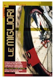
Installazione Pompe<br />
• Infilare sul manubrio, comandi cambio, pompe e<br />
manopole (usare alcool per infilarle con facilità le<br />
manopole)<br />
• Fissare il morsetto delle pompe (1) nella posizione<br />
desiderata (generalmente a 40 - 45°) e quindi bloccare<br />
la vite di fissaggio (2) in alluminio (Ergal) con una<br />
chiave Torx 25. Coppia di serraggio 3Nm<br />
• Le pompe funzionano in qualsiasi posizione variabile<br />
tra l’orizzontale e la verticale. E’ necessario posizionarle<br />
2<br />
1<br />
orizzontali solo durante lo spurgo (vedi Rabbocco del Fluido e Spurgo dell’Aria)<br />
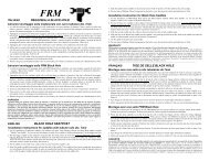
Installazione Pinze<br />
• Prima di fissare le pinze (1) alla forcella ed al telaio, controllate che<br />
ambedue i pistoni siano nella giusta posizione di partenza. Se non lo<br />
fossero, a causa di una accidentale pressione della leva freno, occorre<br />
5<br />
4<br />
inserire al posto delle pastiglie uno spessore da 10mm. Nel Kit Spurgo<br />
è compreso questo specifico distanziale<br />
1<br />
• Con una pinza a becchi sfilare la piccola molla di sicurezza del perno<br />
dei pattini freno. Svitarlo con un cacciavite a lama e sfilare i pattini dal<br />
corpo<br />
3<br />
• Montare il distanziale da 10mm al posto dei pattini e tirare alcune volte<br />
le leve freno per portare i pistoni alla corretta distanza. Rimontare i<br />
pattini con il perno di fissaggio e la molla.<br />
• Se necessario, montare l’adattatore Post-Mount (2), assicurandosi che<br />
la freccia sia rivolta verso l’alto. Vedi tabella nella precedente sezione<br />
“Compatibilità”<br />
• AVVERTENZA: utilizzare solo adattatori originali <strong>FRM</strong>. Altri<br />
adattatori invalidano la garanzia<br />
3<br />
2<br />
4<br />
• Applicare frenafiletti Loctite medio sulle viti (3 e 4) degli adattatori (2) e delle pinze (1)<br />
• Fissare le viti degli adattatori (3) serrandole a 8Nm<br />
• Fissare le pinze (1) direttamente alla forcella o agli adattatori Post-Mount forcella e telaio, a seconda dei casi,<br />
senza per ora serrare definitivamente le due viti di fissaggio (4). Assicurarsi della presenza delle rondelle (5)<br />
sotto la testa delle viti di fissaggio delle pinze (1)<br />
• Per il fissaggio definitivo delle pinze riferirsi al paragrafo “Centratura dei Pattini”<br />
Orientamento Tubazioni<br />
• Orientare il tubo idraulico allentando appena (1/8 di giro) la vite di fissaggio del connettore a Banjo in Ergal<br />
(1) con una chiave da 8mm, serrandola poi a 5Nm dopo aver orientato al meglio la tubazione<br />
• Controllare che la lunghezza dei tubi idraulici sia sufficiente per la dimensione della forcella e del telaio.
Ruotare il manubrio completamente nelle due direzioni e schiacciare la forcella<br />
per verificare che la tubazione non tiri sulle sue estremità e non venga<br />
schiacciata durante la escursione della forcella Agire anche sulla sospensione<br />
posteriore, nel caso di una full, sgonfiando completamente l’ammortizzatore. I<br />
tubi non devono mai tirare sulle loro estremità di fissaggio, ne formare curve<br />
con un diametro di curvatura inferiore a 50mm. Se troppo lunghi, li si può<br />
accorciare, come da successivo paragrafo<br />
• Fissare la tubazione al telaio ed alla forcella per mezzo degli appositi passaggi o<br />
con stringhe da elettricista<br />
Accorciare le Tubazioni<br />
• I terminali della tubazione Frentubo Carbotech sono in alluminio, per<br />
cui occorre prestare attenzione alle specifiche di serraggio<br />
1<br />
4<br />
• Svitare il bullone (1) del banjo (2) con chiave da 8mm<br />
• Fare attenzione ai due piccoli O-Ring (3) posizionati nelle sedi del<br />
connettore banjo<br />
• Tenendo la tubazione bloccata su una morsa svitare il banjo e tirare<br />
con forza per estrarlo dal tubo. Svitare poi il dado di compressione (4)<br />
Mantenere il tubo in verticale per non perdere olio<br />
2<br />
• Posizionare il tubo per trovare la lunghezza giusta, ruotando il<br />
manubrio nelle due direzioni.<br />
3<br />
• Tagliare il tubo a 90° con un taglierino ben affilato (non usare utensili seghettati)<br />
• Avvitare il dado (4) sul tubo. Devono rimanere 6,5mm tra il tubo ed il bordo del dado<br />
• Sempre tenendo il tubo bloccato nella morsa inserire il banjo spingendolo a mano e poi inserendolo<br />
definitivamente con qualche colpetto di martello.<br />
• Avvitare il banjo fino a che non viene a contatto con il dado (4)<br />
• Serrare moderatamente con chiave aperta da 7mm e perno da 6mm infilato nel foro del banjo<br />
• Ungere O-Ring (3) con grasso siliconico. Inserire bullone in Ergal (1) nel banjo (2), avvitarlo alla pompa.<br />
Serrare a 5Nm<br />
Centratura dei Pattini<br />
• Montare le ruote infilando i dischi tra i pattini.<br />
• Assestarle nei forcellini e serrare i rapidi<br />
• Allentare le viti di fissaggio (1) in modo che la pinza<br />
(2) possa spostarsi sul suo supporto<br />
• Agire sulla leva freno (4) e, mentre la si tiene<br />
premuta, serrare le viti di fissaggio delle pinze<br />
• Rilasciare la leva freno e fare girare la ruota. Non<br />
dovrebbe avvertirsi alcun contatto del disco sui<br />
pattini. In caso contrario ripetere l’operazione alcune 4<br />
volte Serrare definitivamente le viti di fissaggio a<br />
8Nm. Dopo il primo periodo di rodaggio è necessario<br />
ripetere questa facilissima operazione per centrare<br />
nuovamente i pattini rispetto ai dischi con tutto il sistema assestato ed i pattini rodati<br />
Sostituire le Tubazioni<br />
• Dovendo sostituire le tubazioni idrauliche agire seguendo questo schema (vedi “Accorciare tubazioni”):<br />
• I terminali della tubazione Frentubo Carbotech sono in alluminio, per cui occorre prestare attenzione alle<br />
specifiche di serraggio<br />
• Verificare che gli O-Ring (3) si trovino all’interno delle sedi su ambedue i lati sia del connettore Banjo (2)<br />
alla pinza che del connettore alla pompa (4). Ingrassare gli O-Ring ed i filetti con il grasso siliconico.<br />
• Avvitare prima il connettore alla pompa (4) e serrarlo con moderazione (3Nm) con chiave aperta da 8mm.<br />
Infilare poi il bullone di fissaggio (1) nel foro del banjo ed avvitarlo alla pinza. Prima di stringerlo<br />
definitivamente, orientare il banjo in modo che la tubazione segua la linea più favorevole. Verificare che gli<br />
1<br />
1<br />
2<br />
3
O-Ring non sporgano dalle loro gole. Serrare a 5Nm<br />
• Procedere come da paragrafo “Rabbocco Fluido e Spurgo dell’Aria”<br />
Regolare le leve freno<br />
• E’ possibile regolare la posizione della leva freno in<br />
modo da variarne la distanza rispetto al manubrio<br />
• Regolare la vite del barilotto (1) sulla leva freno (2) con<br />
una chiave a brugola da 2mm (3). Avvitandola la leva si<br />
avvicina al manubrio<br />
Sostituzione Pastiglie<br />
• Quando le pastiglie sono consumate (non dovrebbe rimanere meno di<br />
0,5mm di materiale frenante), o unte oppure nel caso in cui la<br />
mollettina di ritorno interferisca con il disco, sostituire le pastiglie freno 1<br />
• Rimuovere la ruota dalla bici, sfilare la molla di sicurezza (1) dal perno 3<br />
di fissaggio (2) delle pastiglie (3) e svitarlo con un cacciavite a lama<br />
• Sfilare la coppia di pastiglie dalla pinza<br />
• Posizionare le pompe in modo che il serbatoio dell’olio sia orizzontale<br />
2<br />
• Con un cacciagomme in plastica spingere i pistoni leggermente entro le<br />
loro sedi per recuperare lo spazio per i pattini nuovi<br />
• Con uno straccio imbevuto in alcool pulire i pistoni<br />
• Inserire tra i due pistoni uno spessore da 10mm o l’apposito distanziale incluso nel Kit Spurgo. Premere sulla<br />
leva freno per fare in modo che i due pistoni ne vengano a contatto, quindi smontare il distanziale<br />
• Installare una nuova coppia di pattini e fissarli con il proprio perno e mollettina di sicurezza<br />
• A questo punto seguire le istruzioni riportate nel capitolo “Centratura dei Pattini”<br />
• CONSIGLIABILE: Smontare il coperchio e la membrana del serbatoio dell’olio della pompa. Riempire la<br />
vaschetta con olio nuovo e riposizionare la membrana. Raccogliere con uno straccio la piccola quantità di olio<br />
fuoriesce dal serbatoio. Richiudere il coperchio, serrando le due viti in Ergal a 1,5Nm<br />
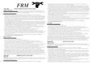
Rabbocco del Fluido e Spurgo dell’Aria<br />
• Procurarsi il Kit Spurgo <strong>FRM</strong><br />
• Indossare guanti di lattice ed occhiali<br />
• Sistemare la bici sul cavalletto di lavoro.<br />
Posizionare la leva freno in modo tale che il<br />
serbatoio dell’olio sia orizzontale al terreno<br />
• Smontare le pastiglie freno per evitare che si<br />
contaminino con l’olio, infilare tra i due<br />
pistoni l’apposito spaziatore in plastica (3<br />
Figura B<br />
Figura A) del Kit Spurgo e fissarlo con il<br />
perno di fissaggio (2 figura A)<br />
• Riempire la siringa del Kit Spurgo di olio Motul DOT 5,1 aspirando da un<br />
contenitore di olio nuovo. Tenere la siringa verticale ed espellere l’aria<br />
• Svitare con la brugola da 2,5mm le viti (1Figura C) che fissano il coperchio<br />
serbatoio (2 Figura C) e togliere sia il coperchio che la membrana in gomma<br />
sottostante. Ideale è infilare la leva in un sacchetto di plastica in modo che olio<br />
che dovesse traboccare si raccolga nel sacchetto<br />
• Svitare Vite di Spurgo sulla pinza. Innestare il connettore siringa nel foro della<br />
Vite Spurgo e immettere olio (Figura B). Mentre si comprime, osservare l’olio<br />
crescere nella vaschetta pompa. Far traboccare olio, insistendo in modo da essere<br />
sicuri che eventuali bolle di aria contenute all’interno delle tubazioni abbiano<br />
modo di fuoriuscire. Non immettere mai aria nel sistema idraulico<br />
• Azionare diverse volte le leve freno per riempire le camere interne e immettere<br />
altro olio dalla siringa per riempire fino all’orlo il serbatoio<br />
• Posizionare la membrana in gomma nella vaschetta del serbatoio, facendone fuoriuscire un poco di olio<br />
• Avvitare il coperchio (2 Figura C) e serrare le viti in Ergal (1 Figura C) a 1,5Nm<br />
2<br />
1<br />
3<br />
1<br />
3<br />
Figura A<br />
2
2<br />
Figura C<br />
1<br />
• Con un elastico tirare la leva freno bloccandola contro il manubrio (Figura C). In tal<br />
modo i fori di passaggio tra impianto idraulico e serbatoio vengono chiusi,<br />
permettendo di spurgare l’aria eventualmente rimasta intrappolata nella pinza.<br />
• Tenendo la siringa in verticale estrarre lentamente il pistone dalla siringa per creare<br />
una leggera depressione nell’impianto. ATTENZIONE: una depressione troppo<br />
elevata potrebbe far aspirare aria dalla tenuta del pistone, che è disegnato per<br />
lavorare sotto pressione e non in depressione, per cui usate moderazione. Si vedranno<br />
bollicine di aria uscire dalla pinza e risalire l’olio nella siringa. Ripetere diverse volte<br />
dando colpetti alle tubazioni ed alla pinza, per esempio con il manico di un<br />
cacciavite, per rimuovere bollicine di aria ferme al loro interno. Il movimento della<br />
siringa diventa sempre più duro mano a mano che l’aria viene aspirata.<br />
• Svitare il connettore siringa. Avvitare la Vite di Spurgo in Ergal serrandola a 2Nm<br />
• Pulire accuratamente i residui di olio sulla pompa e sulla pinza con uno straccio<br />
• Premere la leva freno. Non si deve avvertire una evidente spugnosità. In tal caso<br />
ripetere l’operazione di spurgo fino a che tuta l’aria sia stata estratta dall’impianto<br />
• Smontare il distanziale in plastica e rimontare le pastiglie freno. Avvitare il perno di<br />
fissaggio in Ergal, (2 Figura A) e bloccarlo con la sua clip di sicurezza (1 Figura A)<br />
• Azionare nuovamente le leve freno e controllare che non ci siano perdite di olio in<br />
nessun punto dell’impianto<br />
Problemi e Soluzioni<br />
Nel caso in cui, ad un certo punto del consumo delle pastiglie, la corsa della leva<br />
diventi più lunga del normale e la frenata diminuisca di potenza, aprire il coperchio<br />
della vaschetta del serbatoio per poi richiuderla, in modo che la membrane sottostante<br />
si distenda e ripristini le condizioni originali. Questa operazione di emergenza, che<br />
permette di ripristinare la efficienza dell’impianto, va poi corretta in officina, riaprendo<br />
la vaschetta ed aggiungendo una piccola quantità di olio prima di richiuderla.<br />
Ovviamente, nel momento in cui si dovranno sostituire pastiglie nuove, olio in eccesso impedirà di aprirle tanto<br />
da far passare il disco. In tal caso occorre aprire il tappo del serbatoio, spingere le pastiglie in posizione<br />
interponendo l’apposito distanziale in plastica, facendo uscire il fluido in eccesso e richiudere il coperchio.<br />
Sostituzione Fluido Idraulico<br />
• Quando il fluido idraulico scolorisce si consiglia di sostituirlo. La sostituzione va fatta almeno ogni 2 anni<br />
• Svuotare completamente l’impianto. Posizionare la leva freno in modo che il serbatoio olio sia orizzontale,<br />
svitare le viti che fissano il coperchio e togliere sia il coperchio che la membrana in gomma sottostante<br />
• Smontare le pastiglie freno seguendo le istruzioni precedenti<br />
• Svitare la Vite di Spurgo sul Caliper. Innestare il connettore del Kit di Spurgo nel foro della vite di spurgo ed<br />
aspirare con la siringa tutto l’olio possibile, comprimendo con un cacciagomme in plastica sui pistoni del<br />
caliper fino a fondo, in modo da espellere l’olio contenuto al loro interno<br />
• Svitare il connettore del kit spurgo e lasciare scolare l’olio, facendo in modo che il foro di uscita sia nel punto<br />
più basso. L’olio idraulico è molto aggressivo per cui tamponare con uno straccio e pulire accuratamente tutte<br />
le parti eventualmente contaminate.<br />
• Convenire sempre l’olio idraulico esausto nei contenitori disponibili da distributori, meccanici o centri<br />
raccolta differenziata. Non disperdere nell’ambiente. Un buon biker ama la natura !<br />
• Aspirare nella siringa olio Motul DOT 5,1 possibilmente da una confezione nuova. Avvitare il connettore<br />
della siringa al foro della Vite di Spurgo sul caliper e premere il pistone della siringa per riempire il circuito<br />
idraulico fino a che l’olio non abbia riempito quasi completamente la vaschetta della leva freno<br />
• Seguire le istruzioni del capitolo “ Rabbocco del Fluido e spurgo dell’Aria”<br />
Tabella Coppie Serraggio<br />
Vite a Brugola M6x18 fissaggio pinza Titanio 8Nm<br />
Vite Spurgo Pinza Ergal 2Nm<br />
Bullone fissaggio Banjo tubazione su pinza Ergal 5Nm<br />
Viti M5x10 Torx 25 fissaggio pompa Ergal 3Nm<br />
Vite a brugola M4x10 fissaggio tappo serbatoio Ergal 1,5Nm<br />
Bullone raccordo tubazione su pompa Ergal 3Nm<br />
Viti M5x10 Torx 25 fissaggio dischi Titanio 5N
TABELLA PESI DBR 250 160-140mm gr<br />
KIT ANTERIORE<br />
Post-Mount con Pastiglia Organica supporto alluminio (Pinza-Tubi 85cm-Pompa-Fluido)<br />
167<br />
KIT POSTERIORE<br />
Post-Mount con Pastiglia Organica supporto alluminio (Pinza-Tubi 140cm-Pompa-Fluido)<br />
179<br />
4 viti fissaggio M6x18 Titanio + rondelle 15<br />
<strong>Disco</strong> ant Sawrotor II 160mm 81<br />
<strong>Disco</strong> post Sawrotor II 140mm 67<br />
12 viti fissaggio M5x10 Torx Titanio 14<br />
Adattatore posteriore AU01 per 140mm 16<br />
TOTALE 539<br />
TABELLA PESI DBR 250 160-160mm Gr<br />
KIT ANTERIORE<br />
Post-Mount con Pastiglia Organica supporto alluminio (Pinza-Tubi 85cm-Pompa-Fluido)<br />
167<br />
KIT POSTERIORE<br />
Post-Mount con Pastiglia Organica supporto alluminio (Pinza-Tubi 140cm-Pompa-Fluido)<br />
179<br />
4 viti fissaggio M6x18 Titanio + rondelle 15<br />
<strong>Disco</strong> ant Sawrotor II 160mm 81<br />
<strong>Disco</strong> post Sawrotor II 160mm 81<br />
12 viti fissaggio M5x10 Torx Titanio 14<br />
Adattatore posteriore AU02 per 160mm 21<br />
TOTALE 558<br />
Garanzia<br />
I prodotti <strong>FRM</strong> sono garantiti contro difetti di materiale e costruzione per un periodo di 2 anni dalla data di acquisto del primo utilizzatore, certificata dallo<br />
scontrino fiscale del negozio. La garanzia decade nel caso in cui la manutenzione ordinaria o straordinaria consigliata in questo manuale non sia stata<br />
eseguita OBBLIGHI: in caso di vizio, <strong>FRM</strong> si impegna ad effettuare la sostituzione o la riparazione, a sua discrezione dell’elemento riconosciuto difettoso.<br />
Per essere accettato, il difetto deve essere comunicato dal legittimo proprietario al negoziante dove il prodotto è stato acquistato e da quest’ultimo, dopo<br />
averlo verificato, alla <strong>FRM</strong> Nel caso in cui la <strong>FRM</strong> non riconosca l’esistenza del difetto o stabilisca che questo è dovuto ad una delle cause riportate nel<br />
seguente paragrafo, la sostituzione non è dovuta ed il componente viene restituito a spese del destinatario. LIMITI: la garanzia non copre i danni risultanti<br />
da trasporto, giacenza, incidenti, negligenze, colpi o cadute, mancato rispetto delle informazioni del libretto istruzioni, montaggio errato o con prodotti non<br />
compatibili, cattiva manutenzione, usura normale, modifiche o alterazioni del prodotto. La Garanzia non copre le parti soggette a normale usura (cuscinetti,<br />
paraolio, pattini freno, dischi, ecc.)<br />
Prodotto e distribuito da:<br />
THE BIKE SHOP<br />
Via Mattei 18/a 48025 Riolo Terme (Ra) ITALY<br />
Tel +39 0546 70310 fax 74623<br />
e- mail pubblico: info@frmbike.com<br />
Ordini Italia: barbara@frmbike.biz<br />
e-commerce dalla home page di:<br />
www.frmbike.com
Thank you for purchasing the DBR brake system. Please read this manual before riding your bike<br />
Brake Identification<br />
• This manual describes the DBR 250 model only<br />
• <strong>DBR250</strong> brakes are fitted with titanium hardware to attach calipers and rotors; hydraulic hose Frentubo<br />
Carbotech in braided Carbon Fibre, organicic pads with light alloy backing; steel Sawrotors II available in<br />
the following combinations: 160mm front, 160mm or 140mm rear<br />
Safety Instructions<br />
• Service of these brakes should be performed by qualified professional mechanics who utilise the correct tools,<br />
are familiar with and understand the technical details of hydraulic brake systems and know how this product<br />
works. Ignoring this important safety warning, you accept the connected risks and neither <strong>FRM</strong> nor its<br />
Distributors are responsible for any possible damage.<br />
• WARNING: a Torque Wrench is vital for the correct installation of this brake system<br />
• Verify the correct torque of all fasteners with frequency. Torque ratings are supplied with this manual.<br />
• Frame and fork must be suitable for this type of brake system. Post-Mount adapters must be compatible with<br />
the correct fork brake system and rotor diameter. Wheel hubs must be suitable for the 6 hole standard. Never<br />
build or modify adapters in order to adapt this brake system to frames, forks or wheels which were not built<br />
for this purpose.<br />
• Test brakes and braking technique on flat areas before using the bike in more severe conditions.<br />
• Before each ride check the brakes for proper functioning, the brake pads for wear and the hoses for fluid leak.<br />
• Disc rotors get very hot when used, never touch calipers or rotors immediately after use.<br />
• In case of wet weather the braking performance of all brake systems is vastly reduced. Moderate your speed,<br />
always calculate a longer stopping distance and apply the braking power in a moderate and progressive way.<br />
• A high braking load (total weight over 100kg and an incline of over 15%) will result in a necessary reduction<br />
of speed and the use of both brakes when braking.<br />
• Check to ensure that the front brake is on the side of the handlebar you are accustomed to having it on. If the<br />
lever is on the other side, sudden braking can cause you serious injury. Have a professional mechanic swap<br />
the lever position if incorrect.<br />
• Protect the disc rotors with a clean rag or a piece of cardboard when oiling chain and drive train with aerosol<br />
lubes to avoid contaminations. Do not touch the disc rotors with greasy hands.<br />
• The braking performance is severely limited by rotors or pads contaminated with oil or grease used to<br />
lubricate the bike. Clean with water, isopropyl alcohol or approved brake detergents such as Morgan<br />
Blue/<strong>FRM</strong> Brake Cleaner. Do not spray brake detergents directly on calipers or pumps as their chemical<br />
agents can damage the rubber seals. Disassemble the wheel from the bike and clean the disc rotors. Replace<br />
the brake pads if contaminated.<br />
• If, by any chance, the bike should be left, for a relatively long time, upside-down, air bubbles coming from<br />
the reservoir might travel along the hydraulic hose up to the brake calipers. In this case 4-5 applications of the<br />
brakes are advisable before riding the bike. If the brake lever still feels spongy, keep it applied for a few<br />
minutes giving the air time to travel back along the hose to the pump reservoir. If the problem persists, refer<br />
to the “Bleeding” section of this manual.<br />
• Always install the quick release lever on the opposite side of the hub from the brake caliper. The high<br />
temperature reached by the caliper may weaken the plastic spacer as used by several manufacturers. Long<br />
levers may also interfere with the disc rotor and lock it.<br />
• Use original <strong>FRM</strong> spare parts only. Select the spare part name and code from the “Spare Part Manual” which<br />
can be downloaded from the home page of the web site www.frmbike.com<br />
Break In Period IMPORTANT !!<br />
• All disc brakes need bedding in before they reach the maximum performance.<br />
• This requires at least 30-40 applications of the brakes at a speed of 25-30km/h to an almost complete stop.<br />
After this procedure the break in period can be completed with short (2-3 seconds) brakes on a downhill road,<br />
followed by cooling periods of 5-6 seconds.<br />
Hydraulic Oil<br />
• Use DOT 5,1 or 4,0 only. We suggest the use of the approved Motul DOT 5,1 oil, but hydraulic oils of the<br />
same grade, made by different manufacturers are compatible. NEVER MIX DOT5,0 AND 5,1 OILS: they are
not compatible. NEVER USE MINERAL OILS WITH THIS BRAKE SYSTEM: mineral oil is not<br />
compatible with the rubber seals of this product and will compromise the performance and the functioning of<br />
the system.<br />
• Never use old oils or oil which has been bled out of the system. Old oils coming from opened bottles may<br />
contain water absorbed from the atmospheric humidity. At the high temperatures reached by the disc calipers,<br />
moisture into the oil may boil and form air bubbles (vapour-lock), compromising the braking performance<br />
and causing the brake lever to feel spongy. Open the oil bottle for the least possible time, avoiding<br />
particularly humid places or, even better, use mono-dose bottles (60cc) as supplied by <strong>FRM</strong>. Change brake<br />
fluid every two years maximum.<br />
• All possible oil leakages from hoses or pump reservoirs must be repaired immediately. An oil leak can cause<br />
serious accidents.<br />
• Always wear suitable gloves and protective goggles when using brake fluids.<br />
• If brake fluid comes in contact with the skin, wash immediately with warm water and soap.<br />
• If the product comes in contact with the eyes, call a doctor immediately.<br />
• Always dispose of the used oil in the appropriate containers that can be found at petrol stations, mechanical<br />
workshops etc. Don’t disperse of in nature. Good bikers love nature!<br />
Seals Lubrication<br />
• Use silicon grease for EDPM seals (all rubber type seals that can be found on our brake systems).<br />
• Use of an inappropriate type of grease may compromise the integrity of the seals and damage the system.<br />
Brake Pads<br />
• Brake pads are Shimano XT-XTR (M06 and M07) compatible. Original Shimano brake pads or compatible<br />
products from other pad manufacturers may be used, but we recommend the use of the original <strong>FRM</strong> pads.<br />
• <strong>FRM</strong> pads can be selected from three current designs:<br />
Sinterised (Metallic) pads with steel backing. More aggressive and longer lasting. Perfect for wet weather.<br />
They require a longer break in period. Original equipment on DBR300 DH. Weight 22g. per pair.<br />
Semi-metallic pads with either steel backing. More uniform and progressive braking effect. They wear out<br />
faster than sintered pads. Original equipment on DBR300. Weight 18g. per pair<br />
Organic pads with light alloy backing. Good for X-Country in dry conditions. These pads wear out quite<br />
fast, but are hyper light: 8gr per pair<br />
• With the wheel removed from the bike, take care not to pull the brakes otherwise the pistons can lock. In<br />
this case push the pistons back with a screwdriver or, better, with a plastic tyre remover.<br />
• Brake pads and rotors are not warranted against wear.<br />
Compatibility<br />
• This disc brake system is supplied fully assembled and bled, i.e. containing DOT 5,1 brake fluid.<br />
• This brake system is supplied with the rear Post-Mount adaptor compatible for the requested disc diameter.<br />
The front adaptors vary upon request. They must be chosen between three different designs supplied by <strong>FRM</strong>,<br />
depending on the fork model (International Std or Post-Mount) and disc diameter:<br />
Disc Dia. International Std Fork Post-Mount Fork 160mm Post-Mount Fork 180mm<br />
160mm AU01 adapter Direct mount Not possible<br />
180mm AU02 adapter AU31 adapter Direct mount<br />
Tools<br />
Bleed Kit (Syringe with adapter, plastic pad spacer, 60ml of DOT5,1 oil)<br />
Torx 25 key Beak pliers<br />
Plastic tyre lever Open wrench 7- 8 -10mm<br />
Small screwdriver Dynamometric wrench<br />
Allen keys: 2 - 2,5 - 4 - 5mm<br />
Wheel Spoking<br />
• Never use wheels with radial lacing on both sides with disc brakes. 2 Cross or 3 Cross lacing with traction<br />
spokes facing outboard.<br />
• Assembled wheels are always preferable to wheels built by unskilled wheel builders as the various problems<br />
due to the use of disc brake systems have been analysed and addressed by the wheel manufactures.
Disc Rotor Installation<br />
• Our Sawrotors are compatible with most disc systems from other manufacturers. Install these rotors on<br />
International Standard hubsets with 6 holes, with the laser etched side facing outboard and the orientation as<br />
per the arrow.<br />
• Use one drop medium threadlock compound on the fixing bolts, if not yet present. Do not use permanent<br />
locking compounds. Use a Torx 25 key.<br />
• Progressively tighten the bolts with the following sequence: 1-3-5-2-4-6. End to a torque of 5Nm.<br />
• Check for the rotor planarity by spinning the wheel.<br />
• After a few rides check for the correct torque of the bolts.<br />
Brake Lever Exchange<br />
• Brake levers (pumps) are supplied as follows:<br />
Right Pump – Rear Caliper<br />
Left Pump – Front Caliper<br />
• In case you prefer to switch the brake lever position, unscrew the hose connectors with an 8mm open wrench.<br />
Pay attention to the small O-Ring underneath the connecting bolt.<br />
• Keep the hose vertical as it contains fluid and will leak out if you allow it to swing freely.<br />
• Screw the connector to the opposite pump.<br />
• Gently tighten the hose connecting bolt in light alloy<br />
Brake Lever (Pump) Installation<br />
• Slide shifters, pumps and grips onto the handlebar.<br />
• Attach the lever assembly to the handlebar in the desired<br />
position and angle, tighten the light alloy fixing bolt to a<br />
torque of 3Nm with a Torx 25 key<br />
• Pumps work at any angle from horizontal to 45°. The pump<br />
need only be horizontal when bleeding the system (see<br />
“Bleeding Procedure” section).<br />
Caliper Installation<br />
• Before attaching the calipers to the fork or frame, ensure that the<br />
brake pads are at the correct distance from one another. A 10mm<br />
thick spacer helps to set the pistons to the correct distance (included<br />
5<br />
4<br />
in The Bleed Kit)<br />
• With the aid of small beak pliers remove the tiny spring from the pin<br />
1<br />
that keeps the brake pads in position. Unscrew the pin with a small<br />
screwdriver. Slide the brake pads out of the caliper body.<br />
• Install the 10mm thick plastic spacer in place of the brake pads and<br />
pull the brake lever several times to set the pistons tightly against<br />
3<br />
the spacer.<br />
4<br />
• Reinstall the brake pads with their fixing pin and spring.<br />
• If necessary, install the Post-Mount adapter (2), ensuring that its’<br />
arrow follows the disc rotation. Consult the chart in the previous<br />
paragraph “Compatibility”.<br />
• WARNING: use original <strong>FRM</strong> adaptors only. Adaptors from other<br />
manufacturers may void the warranty.<br />
• Apply one drop of Medium Threadlock Compound on the fixing<br />
bolts (3 and 4).<br />
• Tighten the adaptor bolts (3) to a torque of 8Nm<br />
3<br />
2<br />
• Attach the calipers (1) directly to the fork or to their adaptors (depending on the fork disc mount type), as<br />
well as to the frame, without tightening their fixing bolts (4). Be sure that the steel washer (5) is seated<br />
underneath the bolt head.<br />
• Positioning of the calipers will be explained in the paragraph “Centring the Caliper”<br />
2<br />
1
Rerouting the Hose<br />
• The banjo connector can be rotated to achieve better hose routing. Loosen<br />
the banjo bolt (1) 1/8 of a turn with an 8mm open wrench and, whilst<br />
holding the hose connector in preferred position, re-tighten the light alloy<br />
bolt to a torque of 5Nm.<br />
• Check that both hoses are long enough for the length of the fork and the<br />
frame size. The hoses need to be attached to the fork and frame in such a<br />
way that no interference with the free flow of fluid through the hose may<br />
occur. The hose should not bend in curves any smaller than 50mm diameter.<br />
Check to make sure that the handlebar turns freely and that the hose does<br />
not interfere with any moving parts in the front and rear (if present)<br />
suspensions when compressed. An incorrectly mounted hose or a hose that<br />
comes into contact with moving parts can interfere with the braking<br />
performance and cause serious accidents. In case the hose is too long<br />
proceed as indicated in the following paragraph “Shortening the Hose”<br />
• Attach the hose to the fork or frame through the specific fittings or electric strips.<br />
Shortening The Hose<br />
• The fittings of the Frentubo Carbotech hose are 100% made in light<br />
alloy. Pay great attention to the torque specifications<br />
1<br />
4<br />
• Unscrew the banjo bolt (1) with an 8mm open wrench<br />
• Verify that the O-Rings are fitted into their seats<br />
• With the hose clamped in a vice, unscrew the banjo (2) and then the<br />
compression nut (4) .<br />
• Keep the hose vertical as it contains fluid and will leak out if you<br />
allow it to swing freely<br />
2<br />
• Identify the part of the hose to be cut away, whilst turning the<br />
handlebar to both positions to check length.<br />
3<br />
• Cut the hose at 90° with a sharp cutter (never use knives with serrated blades)<br />
• Screw the compression nut (4) onto the hose until there is 6,5mm space between top of the nut and the hose<br />
• Lubricate the O-Rings (3) and the banjo thread (2) with silicon grease<br />
• With the hose clamped in a vice, insert the banjo into the hose and tap gently to fix in place. Now screw the<br />
banjo into the connecting nut and gently tighten with a 6mm round rod and a 7mm open wrench.<br />
• Slide the banjo fixing bolt (1) into the banjo hole and screw it to the caliper body. Before tightening it rotate<br />
the banjo connector to achieve better hose routing. Verify that the O-Rings are still fitted into their seats<br />
• Tighten the banjo fixing bolt to a torque of 5Nm<br />
Centring the Caliper<br />
• Install the wheels with disc rotors on the bike. Check<br />
for the perfect setting of the hub axle on the fork/frame<br />
dropouts and tighten the quick release lever<br />
3<br />
• Loosen the caliper fixing bolts (1) so that the caliper<br />
body (2) can move and auto align with the disc rotor<br />
• Pull the brake lever and, keeping it pressed, tighten the<br />
fixing bolts (1)<br />
1<br />
• Release the pressure from the brake lever and turn the<br />
wheel. It should turn freely and the rotor should not<br />
come into contact with the brake pads. If it does not<br />
turn freely, repeat the procedure a second time<br />
4<br />
2<br />
• Tighten the bolts to a torque of 8Nm. After the break in period, repeat this easy procedure in order to better<br />
centre the disc rotors on the well bedded pads<br />
Hose Change<br />
• If the hose becomes damaged then replace it. See also paragraph “Shortening the Hose”<br />
• The fittings of the Frentubo Carbotech hose are 100% made in light alloy. Pay attention to the torque specs.<br />
• Verify that the small O-Rings (3) are fitted inside their seats in both the banjo connector on the caliper end,<br />
1
and the connector on the pump end. Lubricate the O-Rings and the bolt threads with silicon grease<br />
• Screw the fitting to the pump FIRST and gently tighten. Next, slide the banjo fixing bolt into the banjo hole<br />
and screw it to the caliper body. Before tightening it, rotate the banjo connector to achieve better hose routing.<br />
Verify that the O-Rings are still fitted into their seats<br />
• Tighten the banjo fixing bolt to a torque of 5Nm<br />
• Proceed as per the paragraph “Bleeding Procedure”<br />
Finger Reach<br />
• The lever position can be adjusted in order to set its’<br />
distance from the handlebar<br />
• Adjust the position of the lever (2) using the adjustment<br />
screw (1) with the aid of a 2mm Allen key (3). Turning<br />
clockwise brings the lever closer to the handlebar<br />
Changing the Brake Pads<br />
• When brake pads are worn out (no less than 0,5mm of brake compound<br />
should ever be present on the pad backing), contaminated with oil or when the<br />
pad spring comes in contact with the rotors, replace the brake pads<br />
1<br />
• Remove the wheel from the bike, remove the retaining spring (1) of the pad 3<br />
pin and unscrew the pad pin (2) with a small screwdriver<br />
• Remove the brake pads (3) from the caliper body<br />
• Loosen the brake lever and position it horizontally<br />
2<br />
• With a plastic tyre lever or a screwdriver push the pistons back<br />
• Clean the pistons inside the caliper with a rag soaked in spirit<br />
• Insert a 10mm spacer between the pistons (this spacer is included in the Bleed<br />
Kit. See Figure A, Nr 3). Pull the brake levers several times to move the pistons in contact with the spacer<br />
• Insert the NEW pads, and fix them with the fixing pin (2) and its retaining spring<br />
• Follow the instructions of paragraph “Centring the Caliper”<br />
• RECCOMENDED: Remove the cap of the brake levers and the rubber diaphragm. Fill the pump reservoir<br />
with fresh oil (DOT5,1), reinstall the diaphragm (fluid will overflow) and the reservoir cap. Tighten the light<br />
alloy fixing bolts to a torque of 1,5Nm<br />
Bleeding Procedure<br />
Figure B<br />
• Purchase the <strong>FRM</strong> Bleed Kit<br />
Figure A<br />
• Wear gloves and protective goggles<br />
1<br />
• With the bike on a working stand remove wheels<br />
• Position the brake levers horizontally<br />
3<br />
• Remove the brake pads as they risk being<br />
contaminated by hydraulic oil, insert in their<br />
place the plastic spacer (Figure A, Nr 3)<br />
2<br />
included with the Bleed Kit and fix it with the<br />
Pad Pin ( Figure A, Nr 2)<br />
• Fill the Bleed Kit syringe with fresh Motul DOT 5,1 oil. Keep the syringe vertical<br />
and push out the air bubbles<br />
• Unscrew the pump cap bolt (Figure C, Nr 2) with a 2,5mm Allen key, remove the<br />
cap (Figure C, Nr 1) and the rubber diaphragm. It is advisable to put the brake<br />
lever into a plastic bag so that the hydraulic fluid which might overflow does not<br />
drip onto the floor.<br />
• Unscrew the bleed bolt from the caliper. Screw the syringe into its’ hole. Pump oil<br />
into the system through the syringe (Figure B). Whilst pumping into the system<br />
observe the fluid as it fills the pump reservoir. Overflow the brake fluid until no<br />
more air bubbles appear in the reservoir. Pay attention to not pump air into the<br />
system through the syringe.<br />
• Pull the brake levers several times so that the brake fluid can fill up all chambers<br />
of the master cylinder. Fill the reservoir with more fluid if necessary.<br />
2<br />
1<br />
3
2<br />
Figure<br />
C<br />
1<br />
• Position the rubber diaphragm on the reservoir (fluid will overflow)<br />
• Reinstall the reservoir cap (Figure C, Nr 1) on the pump. Tighten the two fixing bolts<br />
in light alloy (Figure C, Nr 2) to a torque of 1,5Nm<br />
• Use a rubber band to hold the brake lever (Figure C) pulled. In this case the oil ports<br />
between the brake system and the reservoir are closed and air eventually trapped into<br />
the hydraulic system can be bled.<br />
• Whilst keeping the syringe vertical, pull its plunger upward (Figure C) in order to<br />
create a depression and suck out any air contained in the system. Repeat this operation<br />
3-4 times, making sure that any air present in the form of bubbles has been expelled<br />
from the caliper and collected in the syringe. Gently tap the caliper body with the<br />
plastic handle of a screwdriver to force the air bubbles out. WARNING: The master<br />
cylinder seal is devised to work when pressurised and not when depressurised, which<br />
means that pulling the syringe plunger too hard might cause a blow-by. Do not overpull<br />
• When all air bubbles are sucked into the syringe, push gently on the plunger to be sure<br />
that brake fluid has replaced the air<br />
• Unscrew the syringe connector and reinstall the bleed bolt to a torque of 2Nm<br />
• Carefully clean the overflow of oil from the pump with a clean rag<br />
• Pull the brake lever a few time to check the system strength and the absence of air.<br />
Repeat the bleed procedure if the lever feels spongy<br />
• Remove the plastic spacer and reassemble the brake pads. Fix them with the fixing pin<br />
(Figure A, Nr 2) and its retaining spring (Figure A, Nr 1)<br />
• Pull the brake lever and check for any oil leakage from the hydraulic system<br />
ATTENTION: To make sure that the Bleeding process has functioned correctly, the<br />
brake levers should be pulled very tightly and fixed down with plastic ties. The bike<br />
should then be left with the levers like this in a vertical position overnight.<br />
Change of the Brake Fluid<br />
• The brake fluid must be replaced when exhausted. It must be replaced every two years when used regularly or<br />
once a year when used by racers with extensive bike use<br />
• Clean the old oil from the hydraulic system:<br />
Position the brake levers horizontally and remove both the cap and the rubber diaphragm<br />
Remove the brake pads following the instructions in paragraph “Bleeding Procedure”<br />
Unscrew the bleed bolt from the caliper and attach the syringe. Suck all oil from the hydraulic system<br />
pulling the syringe plunger, whilst compressing the caliper pistons all the way into their bores, in order to<br />
expel all the fluid from the system<br />
Unscrew the syringe connector and leave the fluid to drain freely. Brake fluid is quite aggressive, so clean<br />
all contaminated parts with a clean rag<br />
• Always dispose of the used oil in the appropriate containers that can be found at petrol stations, mechanical<br />
workshops etc. Don’t disperse of in nature. Good bikers love nature!<br />
• Follow the instructions in paragraph “Bleeding Procedure”<br />
Problems and Solutions<br />
If, after a certain amount of pad has been consumed, the lever travel is longer than before the problem can be<br />
resolved in urgent cases by opening the reservoir cap and re-closing it again. This releases the pressure on the<br />
membrane. If more time is available and replacement oil is on hand, oil can be added to the reservoir before reclosing.<br />
Obviously, after this addition, when new pads are installed there will be too much oil. With the<br />
reservoir cap open and the pads pushed back in to position, the excess oil will overflow out of the reservoir.<br />
Bolt Torque Chart<br />
Allen M6x18 – Caliper Fixing Bolt Titanium 8 Nm<br />
Bleed Bolt Light Alloy 2 Nm<br />
Banjo Bolt Light Alloy 5 Nm<br />
Allen M5x10 – Pump Fixing Bolt Light Alloy 3 Nm<br />
Allen M4x10 – Pump Cap Fixing Bolt Light Alloy 1,5 Nm<br />
Hose Connector to the Pump Light Alloy 3 Nm<br />
M5x10 Torx 25 – Rotor Fixing Bolt Titanium 5 Nm
DBR 250 140-160mm WEIGHT CHART g<br />
FRONT KIT<br />
Post-Mount with Organicic-Alloy Backing brake pads (Caliper-Hose 85cm-Pump-Fluid)<br />
167<br />
REAR KIT<br />
Post-Mount with Organic-Alloy Backing brake pads (Caliper-Hose 140cm-Pump-Fluid)<br />
179<br />
4 Allen Bolts M6x16 & Washers – Titanium 15<br />
Front Disc Sawrotor II 160mm 81<br />
Rear Disc Sawrotor II 140mm 67<br />
12 M5x10 Disc Fixing Bolts - Titanium 14<br />
Post-Mount Adapter AU01 for 140mm rear rotor 16<br />
TOTAL 539<br />
DBR 250 160-160mm WEIGHT CHART G<br />
FRONT KIT<br />
Post-Mount with Organic-Alloy Backing brake pads (Caliper-Hose 85cm-Pump-Fluid)<br />
167<br />
REAR KIT<br />
Post-Mount with Organic-Alloy Backing brake pads (Caliper-Hose 140cm-Pump-Fluid)<br />
179<br />
4 Allen Bolts M6x16 & Washers – Titanium 15<br />
Front Disc Sawrotor II 160mm 81<br />
Rear Disc Sawrotor II 160mm 81<br />
12 M5x10 Disc Fixing Bolts - Titanium 14<br />
Post-Mount Adapter AU02 for 160mm rear rotor 21<br />
TOTAL 558<br />
Warranty<br />
<strong>FRM</strong> products are guaranteed against any defects for a period of 2 years from the date of purchase by the first owner,<br />
registered in a dealer shop. OBLIGATIONS: In case of defects, <strong>FRM</strong> pledge to replace or repair, at their discretion, the part<br />
recognised as defective. To be accepted, the rider compliant must be communicated to <strong>FRM</strong> through the dealer/importer after his own<br />
control. If <strong>FRM</strong> after sales checking reveals that the damage is due to one of the reasons mentioned in the following paragraph, the<br />
replacement is no longer accepted and the defective item is sent back to the plaintiff who supports the shipping fees. LIMITATIONS:<br />
The guarantee does not cover damage resulting from transportation, warehousing, accidents, negligence, impact or falls, noncompliance<br />
with the information in the instruction manuals, assembly errors, assembly using non-compatible products, bad<br />
maintenance, modifications or alterations to the product. The guarantee does not cover parts and components subject to normal wear<br />
and tear such as ball-bearings, bushings, seals, brake pads, disc rotors, etc.<br />
Manufactured by:<br />
THE BIKE SHOP<br />
Via Mattei 18/a 48025 Riolo Terme (Ra) ITALY<br />
Phone +39 0546 70310 fax 74623<br />
General e-mail : info@frmbike.com<br />
Foreign orders: jane@frmbike.biz<br />
e-commerce from the home page of www.frmbike.com<br />
www.frmbike.com<br />
15