motocoltivatoremotor - cultivatormehrzweckge r ä tmotoculteurmotocult
motocoltivatoremotor - cultivatormehrzweckge r ä tmotoculteurmotocult
motocoltivatoremotor - cultivatormehrzweckge r ä tmotoculteurmotocult

Create successful ePaper yourself
Turn your PDF publications into a flip-book with our unique Google optimized e-Paper software.
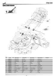
care the holes to line up with the screws seatings and screw the 6 pcs. screws again (5). Then carefully screw the support (7) screws (6) as well.<br />
Assembly of the hinge engine hood rotary cutter (Fig.4) put the hinge hooks (part. 1) keeping it turning to the top side into the slots<br />
on the engine hood milling, lower the hinge and screw down the plates (2) with the relevant screws (3). ATTENTION ! The strap should be placed<br />
with the hooks placed as shown in the picture specs. This is to say that the hooks should enter from top to down into the hole “B” and come our from<br />
“A” position.<br />
ADJUSTMENTS<br />
Adjustment of the belt stretcher driving wire single speed and reverse (Fig.5) Attention , the wheels have to start working<br />
only when the control lever has moved halfway its travel. When the lever is completely pulled (working position), the spring load of the belt stretcher<br />
(part. 1 single speed) and (part.2 reverse speed) must extend for 6-8 mm. In order to obtain he a.m. conditions you have to act on the regulator<br />
(3) you can see near the drive control lever. The transmission reverse REV. (4) the lever on position released should have some clearance on the<br />
registers. Please, carefully check from time to time the adjustement of the two transmissions in order to avoid the belts sliding and the<br />
consequent pulleys overheating.<br />
Adjustment of the handlebar position (Fig.6) The handlebar position can be height adjusted. Before starting any work it is a good standard<br />
operating procedure to adjust the handlebar to the operator’s requirements so that the machine could be easily handled. The particular shape of of<br />
the single speed control lever allows the operator to drive the machine from the right or the left side in order not to thread on the cultivated ground nor<br />
to squash the vegetation. Unscrew down the handlebar support screws (part. 1). Adjust to the suitable/requested position, block the screws (1).<br />
Depht adjustment (Fig.7) In order to obtain a good soil cultivation and a smooth machine movement , the cultivators is equipped with a depth<br />
setting device (part.2) which regulates the spade working depth. When the depth control lever is pulled is pulled back (1) and moving the same up<br />
or down, you can regulated spade penetration into the soil: the adjustment is correct when the machine when the machine moves forward smoothly<br />
without lifting out or digging into the soil.<br />
- Hard soils cultivation: bring the depth to position (B). such postion corresponds to a small soil penetration.<br />
- Soft soils penetration: Bring the depth to position (A). suc position corresponds to a deept soil penetration depth.<br />
When moving with the machine working on different surfaces, keep the depth on position (B) in order to avoid the spades to break up the top<br />
of the surface.<br />
E N G L I S H<br />
CONTROLS DESCRIPTION (Fig.8) 1) Accelerator lever control Start-Stop 2) Forward speed lever control. 3) Forward speed lever control<br />
4) Control speed SLOW-FAST (2+2 speed version only) 5) “Fork on 3 positions” 6) Starter handle 7) Root face control lever.<br />
INSTRUCTIONS<br />
Following the assembly & adjustment operations the motorcultivator is ready to start working.<br />
ATTENTION ! Before switching the engine on, carefully check if the motorcultivator is in perfect good conditions.<br />
- Engine instructions: Carefully read the istructions booklet anclosed to the relevant engine.<br />
- Check if the air filter is clean.<br />
- Fill the tank in as per the fuel described in the engine specifications and using a filter filling funnel.<br />
- Do not change the calibration of the speeds control rotation device of the engine in order not to over-speed it.<br />
- Put the fork (Fig.2) into position 1 (free) so that the wheel could freely turn on the shaft to allow the movements.<br />
8