Dimplex_LIH 22-26TE 3-sprachig D-GB-F.book - enrdd.com
Dimplex_LIH 22-26TE 3-sprachig D-GB-F.book - enrdd.com
Dimplex_LIH 22-26TE 3-sprachig D-GB-F.book - enrdd.com

Create successful ePaper yourself
Turn your PDF publications into a flip-book with our unique Google optimized e-Paper software.
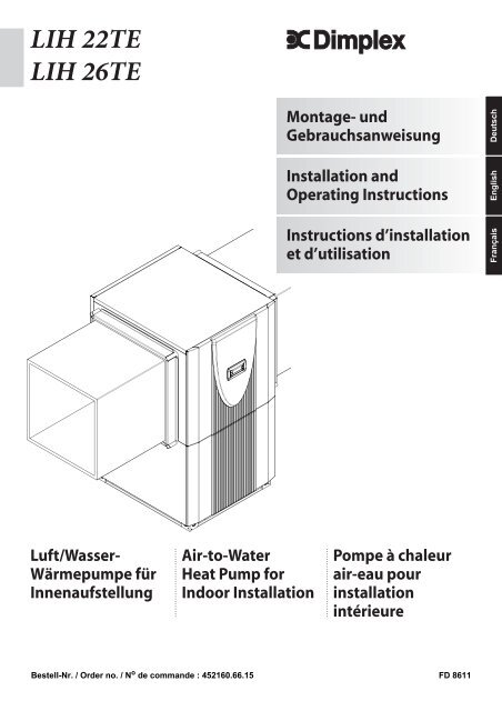
<strong>LIH</strong> <strong>22</strong>TE<br />
<strong>LIH</strong> <strong>26TE</strong><br />
Montage- und<br />
Gebrauchsanweisung<br />
Deutsch<br />
Installation and<br />
Operating Instructions<br />
English<br />
Instructions d’installation<br />
et d’utilisation<br />
Français<br />
Luft/Wasser-<br />
Wärmepumpe für<br />
Innenaufstellung<br />
Air-to-Water<br />
Heat Pump for<br />
Indoor Installation<br />
Pompe à chaleur<br />
air-eau pour<br />
installation<br />
intérieure<br />
Bestell-Nr. / Order no. / N o de <strong>com</strong>mande : 452160.66.15 FD 8611
Inhaltsverzeichnis<br />
1 Bitte sofort lesen .......................................................................................................................... D-2<br />
1.1 Wichtige Hinweise ..................................................................................................................................D-2<br />
1.2 Gesetzliche Vorschriften und Richtlinien ................................................................................................D-2<br />
2 Verwendungszweck der Wärmepumpe...................................................................................... D-2<br />
2.1 Anwendungsbereich ...............................................................................................................................D-2<br />
2.2 Arbeitsweise ...........................................................................................................................................D-2<br />
Deutsch<br />
3 Lieferumfang................................................................................................................................. D-3<br />
3.1 Grundgerät..............................................................................................................................................D-3<br />
3.2 Schaltkasten ...........................................................................................................................................D-3<br />
3.3 Wärmepumpenregler ..............................................................................................................................D-3<br />
4 Transport....................................................................................................................................... D-4<br />
5 Aufstellung.................................................................................................................................... D-4<br />
5.1 Allgemein ................................................................................................................................................D-4<br />
5.2 Kondensatleitung ....................................................................................................................................D-4<br />
5.3 Schall ......................................................................................................................................................D-4<br />
6 Montage......................................................................................................................................... D-5<br />
6.1 Allgemein ................................................................................................................................................D-5<br />
6.2 Luftanschluss..........................................................................................................................................D-5<br />
6.3 Heizungsseitiger Anschluss....................................................................................................................D-5<br />
6.4 Elektrischer Anschluss............................................................................................................................D-6<br />
7 Inbetriebnahme............................................................................................................................. D-6<br />
7.1 Allgemein ................................................................................................................................................D-6<br />
7.2 Vorbereitung ...........................................................................................................................................D-6<br />
7.3 Vorgehensweise .....................................................................................................................................D-6<br />
8 Reinigung / Pflege ........................................................................................................................ D-7<br />
8.1 Pflege......................................................................................................................................................D-7<br />
8.2 Reinigung Heizungsseite ........................................................................................................................D-7<br />
8.3 Reinigung Luftseite .................................................................................................................................D-8<br />
9 Störungen / Fehlersuche ............................................................................................................. D-8<br />
10 Außerbetriebnahme / Entsorgung .............................................................................................. D-8<br />
11 Geräteinformation ........................................................................................................................ D-9<br />
12 Garantieurkunde......................................................................................................................... D-10<br />
Anhang / Appendix / Annexes ............................................................................................................ A-I<br />
www.dimplex.de D-1
1<br />
Deutsch<br />
1 Bitte sofort lesen<br />
1.1 Wichtige Hinweise<br />
ACHTUNG!<br />
Die Wärmepumpe darf beim Transport nur bis zu einer Neigung von 45°<br />
(in jeder Richtung) gekippt werden.<br />
ACHTUNG!<br />
Wärmepumpe und Transportpalette sind nur durch die Verpackungsfolie<br />
verbunden.<br />
ACHTUNG!<br />
Der Ansaug- und Ausblasbereich darf nicht eingeengt oder zugestellt<br />
werden.<br />
ACHTUNG!<br />
Die Wärmepumpe darf nur mit angebauten Luftkanälen betrieben werden.<br />
ACHTUNG!<br />
Rechtsdrehfeld beachten: Bei Betrieb der Verdichter mit falscher<br />
Drehrichtung kann es zu Verdichterschäden kommen.<br />
ACHTUNG!<br />
Verwenden Sie nie sand-, soda-, säure- oder chloridhaltige Putzmittel, da<br />
diese die Oberfläche angreifen.<br />
ACHTUNG!<br />
Zur Vermeidung von Ablagerungen (z.B. Rost) im Kondensator der<br />
Wärmepumpe wird empfohlen, ein geeignetes Korrosionsschutzsystem<br />
einzusetzen.<br />
ACHTUNG!<br />
Vor Öffnen des Gerätes ist sicherzustellen, dass alle Stromkreise<br />
spannungsfrei geschaltet sind.<br />
ACHTUNG!<br />
Arbeiten an der Wärmepumpe dürfen nur vom autorisierten und<br />
sachkundigen Kundendienst durchgeführt werden.<br />
1.2 Gesetzliche Vorschriften und<br />
Richtlinien<br />
Bei der Konstruktion und Ausführung der Wärmepumpe wurden<br />
alle entsprechenden EG-Richtlinien, DIN- und VDE-Vorschriften<br />
eingehalten (siehe CE-Konformitätserklärung).<br />
Beim elektrischen Anschluss der Wärmepumpe sind die entsprechenden<br />
VDE-, EN- und IEC-Normen einzuhalten. Außerdem<br />
müssen die Anschlussbedingungen der Versorgungsnetzbetreiber<br />
beachtet werden.<br />
Beim Anschließen der Heizungsanlage sind die einschlägigen<br />
Vorschriften einzuhalten.<br />
Personen, insbesondere Kinder, die aufgrund ihrer physischen,<br />
sensorischen oder geistigen Fähigkeiten oder ihrer Unerfahrenheit<br />
oder Unkenntnis nicht in der Lage sind, das Gerät sicher zu<br />
benutzen, sollten dieses Gerät nicht ohne Aufsicht oder Anweisung<br />
durch eine verantwortliche Person benutzen.<br />
Kinder sollten beaufsichtigt werden, um sicher zu stellen, dass<br />
sie nicht mit dem Gerät spielen.<br />
2 Verwendungszweck der<br />
Wärmepumpe<br />
2.1 Anwendungsbereich<br />
Die Hochtemperatur-Luft-Wasser-Wärmepumpe ist für die Sanierung<br />
bestehender Heizungsanlagen einsetzbar, wenn Vorlauftemperaturen<br />
bis 75 °C erforderlich sind.<br />
Die Wärmepumpe ist ausschließlich für die Erwärmung von<br />
Heiz- und Brauchwasser konzipiert!<br />
Die Wärmepumpe ist für den monoenergetischen und bivalenten<br />
Betrieb bis -20 °C Luftaußentemperatur geeignet.<br />
Im Dauerlauf ist eine Temperatur des Heizwasserrücklaufs von<br />
mehr als 18 °C einzuhalten, um ein einwandfreies Abtauen des<br />
Verdampfers zu gewährleisten.<br />
2.2 Arbeitsweise<br />
Außenluft wird vom Ventilator angesaugt und dabei über den<br />
Verdampfer (Wärmetauscher) geleitet. Der Verdampfer kühlt die<br />
Luft ab, d.h. er entzieht ihr Wärme. Die gewonnene Wärme wird<br />
im Verdampfer auf ein Arbeitsmedium (Kältemittel) übertragen.<br />
Mit Hilfe der elektrisch angetriebenen Verdichter wird die aufgenommene<br />
Wärme durch Druckerhöhung auf ein höheres Temperaturniveau<br />
"gepumpt" und über den Verflüssiger (Wärmeaustauscher)<br />
an das Heizwasser abgegeben.<br />
Dabei wird die elektrische Energie eingesetzt, um die Wärme der<br />
Umwelt auf ein höheres Temperaturniveau anzuheben. Da die<br />
der Luft entzogene Energie auf das Heizwasser übertragen wird,<br />
bezeichnet man dieses Gerät als Luft-Wasser-Wärmepumpe.<br />
Die Luft-Wasser-Wärmepumpe besteht aus den Hauptbauteilen<br />
Verdampfer, Ventilator und Expansionsventil, sowie den geräuscharmen<br />
Verdichtern, dem Verflüssiger und der elektrischen<br />
Steuerung.<br />
Bei tiefen Umgebungstemperaturen lagert sich Luftfeuchtigkeit<br />
als Reif auf dem Verdampfer an und verschlechtert die Wärmeübertragung.<br />
Der Verdampfer wird durch die Wärmepumpe nach<br />
Bedarf automatisch abgetaut. Je nach Witterung können dabei<br />
Dampfschwaden am Luftausblas entstehen.<br />
D-2
3.3<br />
3 Lieferumfang<br />
3.1 Grundgerät<br />
Die Wärmepumpe wird in Kompaktbauweise geliefert und enthält<br />
unten aufgeführte Bauteile.<br />
Als Kältemittel wird R404A und R134a verwendet.<br />
<br />
3.2 Schaltkasten<br />
Der Schaltkasten befindet sich in der Wärmepumpe. Nach Abnahme<br />
der unteren Frontabdeckung und dem Lösen der sich<br />
rechts oben befindenden Befestigungsschraube kann der<br />
Schaltkasten herausgeklappt werden.<br />
Im Schaltkasten befinden sich die Netzanschlussklemmen,<br />
sowie die Leistungsschütze, die Sanftanlauf-Einheit und der<br />
Wärmepumpenmanager.<br />
3.3 Wärmepumpenregler<br />
Deutsch<br />
Der Wärmepumpenmanager ist ein komfortables elektronisches<br />
Regel- und Steuergerät. Er steuert und überwacht die gesamte<br />
Heiz- bzw. Kühlanlage in Abhängigkeit von der Außentemperatur,<br />
die Warmwasserbereitung und die sicherheitstechnischen<br />
Einrichtungen.<br />
Der bauseits anzubringende Außentemperaturfühler incl. Befestigungsmaterial<br />
liegt dem Regler bei.<br />
Funktionsweise und Handhabung des Wärmepumpenmanagers<br />
sind in der beiliegenden Gebrauchsanweisung beschrieben.<br />
<br />
1) Verdampfer<br />
2) Rückschlagventil<br />
3) Ventilator<br />
4) Schaltkasten<br />
5) Pressostate<br />
6) Verflüssiger<br />
7) Filtertrockner<br />
8) Verdichter R404A<br />
9) Verdichter R134a<br />
www.dimplex.de D-3
4<br />
4 Transport<br />
5 Aufstellung<br />
Deutsch<br />
ACHTUNG!<br />
Die Wärmepumpe darf beim Transport nur bis zu einer Neigung von 45°<br />
(in jeder Richtung) gekippt werden.<br />
Der Transport zum endgültigen Aufstellungsort sollte mit Holzrost<br />
erfolgen. Das Grundgerät bietet einerseits die Transportmöglichkeit<br />
mit Hubwagen, Sackkarre o.ä., oder mittels 3/4"<br />
Rohren, die durch Bohrungen in der Grundplatte, bzw. im Rahmen<br />
geführt werden.<br />
5.1 Allgemein<br />
Das Gerät ist grundsätzlich in Innenräumen auf einer ebenen,<br />
glatten und waagrechten Fläche aufzustellen. Dabei sollte der<br />
Rahmen rundum dicht am Boden anliegen, um eine geeignete<br />
Schallabdichtung zu gewährleisten. Ist dies nicht der Fall, können<br />
zusätzliche schalldämmende Maßnahmen notwendig werden.<br />
Die Aufstellung auf einem Unterstellpuffer erfordert zwingend<br />
eine voll umlaufende Auflage. Die Wärmepumpe muss so<br />
aufgestellt sein, dass Wartungsarbeiten problemlos durchgeführt<br />
werden können. Dies ist gewährleistet, wenn ein Abstand von je<br />
1 m an der Frontseite sowie links und rechts der Wärmepumpe<br />
eingehalten wird.<br />
<br />
<br />
<br />
ACHTUNG!<br />
Wärmepumpe und Transportpalette sind nur durch die Verpackungsfolie<br />
verbunden.<br />
Zur Nutzung der Transportbohrungen im Rahmen ist es notwendig<br />
die unteren Fassadierungsteile abzunehmen. Dazu werden<br />
jeweils zwei Schrauben am Sockel gelöst und die Bleche durch<br />
Zurückziehen, oben ausgehängt. Beim Einhängen der Blechteile<br />
sollten diese mit leichtem Druck nach oben geschoben werden.<br />
Beim Durchstecken der Tragrohre durch den Rahmen ist darauf<br />
zu achten, dass keine Bauteile beschädigt werden.<br />
<br />
Das Gerät sollte nie in Räumen mit hoher Luftfeuchtigkeit aufgestellt<br />
werden. Bei Luftfeuchtigkeiten von über 50% und Außentemperaturen<br />
unter 0 °C kann an der Wärmepumpe und der Luftführung<br />
Kondensat entstehen.<br />
Bei Installation der Wärmepumpe in einem Obergeschoss, ist die<br />
Tragfähigkeit der Decke zu prüfen und aus akustischen Gründen<br />
die Schwingungsentkoppelung sehr sorgfältig zu planen. Eine<br />
Aufstellung auf einer Holzdecke ist abzulehnen.<br />
5.2 Kondensatleitung<br />
<br />
<br />
<br />
<br />
<br />
<br />
Das im Betrieb anfallende Kondensatwasser muss frostfrei abgeleitet<br />
werden. Um einen einwandfreien Abfluss zu gewährleisten,<br />
muss die Wärmepumpe waagerecht stehen. Das Kondensatwasserrohr<br />
muss mindestens einen Durchmesser von 50 mm<br />
haben und sollte frostsicher in den Abwasserkanal geführt werden.<br />
Kondensat nicht direkt in Klärbecken und Gruben einleiten,<br />
da die aggressiven Dämpfe den Verdampfer zerstören können.<br />
<br />
Öffnen des Deckels<br />
<br />
Schließen des Deckels<br />
5.3 Schall<br />
Um Körperschallübertragungen ins Heizsystem zu vermeiden,<br />
empfiehlt es sich, die Wärmepumpe mit einem flexiblen<br />
Schlauch an das Heizsystem anzubinden.<br />
Verwendete Luftkanäle sind schalltechnisch von der Wärmepumpe<br />
zu entkoppeln, um eine Körperschallübertragung auf die<br />
Kanäle zu vermeiden.<br />
D-4
6.3<br />
6 Montage<br />
6.1 Allgemein<br />
<br />
An der Wärmepumpe sind folgende Anschlüsse herzustellen:<br />
• Zu-/Abluft<br />
• Vor-/Rückläufe der Heizungsanlage<br />
• Kondensatablauf<br />
• Stromversorgung<br />
<br />
Deutsch<br />
6.2 Luftanschluss<br />
ACHTUNG!<br />
Der Ansaug- und Ausblasbereich darf nicht eingeengt oder zugestellt<br />
werden.<br />
<br />
ACHTUNG!<br />
Die Wärmepumpe darf nur mit angebauten Luftkanälen betrieben werden.<br />
Die als Zubehör angebotenen Luftkanäle aus Glas-faserleichtbeton<br />
sind feuchtigkeitsbeständig und diffusionsoffen.<br />
Die Dichtmanschette wird zur Abdichtung der Luftkanäle an der<br />
Wärmepumpe verwendet. Die Luftkanäle selbst werden nicht direkt<br />
mit der Wärmepumpe verschraubt. Im betriebsfertigen Zustand<br />
berührt lediglich der Dichtgummi die Wärmepumpe. Dadurch<br />
ist zum einen eine leichte Montage und Demontage der<br />
Wärmepumpe gewährleistet, zum anderen wird eine gute Körperschallentkopplung<br />
erreicht.<br />
Wird ein anderer als der als Zubehör erhältliche Luftkanal verwendet,<br />
so sind die in der Skizze genannten Außen- und Innenmaße<br />
einzuhalten. Zusätzlich ist auf geeignete Schwingungsentkopplung<br />
und Kanalisolation zu achten.<br />
Bei der Verwendung von angeflanschten Luftkanälen wird je ein<br />
Anschlussstutzen an der Ansaug- und Ausblasseite des Verdampfers<br />
mit 4 Sechskantschrauben M8x16 an den vorgesehenen<br />
Gewindelöchern befestigt. Dabei ist zu beachten, dass beide<br />
Luftkanalstutzen nur mit der Isolierung und nicht mit dem Außenblech<br />
in Berührung kommen.<br />
<br />
6.3 Heizungsseitiger Anschluss<br />
Die heizungsseitigen Anschlüsse an der Wärmepumpe sind mit<br />
1 1/4" Außengewinde versehen. Beim Anschluss an die Wärmepumpe<br />
muss an den Übergängen mit einem Schlüssel gegengehalten<br />
werden.<br />
Bevor die heizwasserseitigen Anschlüsse der Wärmepumpe erfolgen,<br />
muss die Heizungsanlage gespült werden, um eventuell<br />
vorhandene Verunreinigungen, Reste von Dichtmaterial oder<br />
ähnliches zu entfernen. Ein Ansammeln von Rückständen im<br />
Verflüssiger kann zum Totalausfall der Wärmepumpe führen. Für<br />
Anlagen mit absperrbarem Heizwasserdurchfluss, bedingt durch<br />
Heizkörper- bzw. Thermostatventile, muss ein Überströmventil<br />
bauseits hinter der Heizungspumpe in einem Heizungsbypass<br />
eingebaut werden. Dies sichert einen Mindestheizwasserdurchfluss<br />
durch die Wärmepumpe und verhindert Störungen.<br />
Nach erstellter heizungsseitiger Installation ist die Heizungsanlage<br />
zu füllen, zu entlüften und abzudrücken.<br />
Mindestheizwasserdurchsatz<br />
Der Mindestheizwasserdurchsatz der Wärmepumpe ist in jedem<br />
Betriebszustand der Heizungsanlage sicherzustellen. Dieses<br />
kann z.B. durch Installation eines differenzdrucklosen Verteilers<br />
oder eines Überströmventiles erreicht werden. Die Einstellung<br />
eines Überströmventiles ist in Kapitel Inbetriebnahme erklärt.<br />
www.dimplex.de D-5
6.4<br />
Deutsch<br />
Frostschutz<br />
Bei Wärmepumpen, die frostgefährdet aufgestellt sind, sollte<br />
eine manuelle Entleerung (siehe Bild) vorgesehen werden. Sofern<br />
Regler und Heizungsumwälzpumpe betriebsbereit sind, arbeitet<br />
die Frostschutzfunktion des Reglers. Bei Außerbetriebnahme<br />
der Wärmepumpe oder Stromausfall ist die Anlage zu<br />
entleeren. Bei Wärmepumpenanlagen, an denen ein Stromausfall<br />
nicht erkannt werden kann (Ferienhaus), ist der Heizungskreis<br />
mit einem geeigneten Frostschutz zu betreiben.<br />
7 Inbetriebnahme<br />
7.1 Allgemein<br />
Um eine ordnungsgemäße Inbetriebnahme zu gewährleisten,<br />
sollte diese von einem vom Werk autorisierten Kundendienst<br />
durchgeführt werden. Unter bestimmten Bedingungen ist damit<br />
eine Verlängerung der Gewährleistung verbunden (vgl. Garantieleistung).<br />
6.4 Elektrischer Anschluss<br />
Die Leistungsversorgung und Steuerspannung werden über<br />
handelsübliche Leitungen zugeführt (Last: 4-adrig, Steuerung<br />
3-adrig).<br />
In der Leistungsversorgung für die Wärmepumpe ist eine allpolige<br />
Abschaltung mit mindestens 3 mm Kontaktöffnungsabstand<br />
(z.B. EVU-Sperrschütz, Leistungsschütz), sowie ein 3-poliger Sicherungsautomat,<br />
mit gemeinsamer Auslösung aller Außenleiter,<br />
vorzusehen (Auslösestrom gemäß Geräteinformation).<br />
Beim Anschließen ist das Rechtsdrehfeld der Lasteinspeisung<br />
sicherzustellen L1; L2; L3.<br />
ACHTUNG!<br />
Rechtsdrehfeld beachten: Bei Betrieb der Verdichter mit falscher<br />
Drehrichtung kann es zu Verdichterschäden kommen.<br />
Die Steuerspannung muss mit 10 A abgesichert werden.<br />
Die Stromversorgung des Wärmepumpenreglers mit 230V AC-<br />
50 Hz, erfolgt gemäß seiner eigenen Gebrauchsanweisung (Absicherung<br />
16 A).<br />
Die vormontierte, 7 m lange Steuerleitung wird mit den beiden<br />
rechteckigen Steckverbindern und den beiden Einzeladern (integrierter<br />
Rücklauffühler) mit dem für die Steuerung benötigten<br />
Wärmepumpenregler verbunden. Genauere Anweisungen sind<br />
der Gebrauchsanweisung des Wärmepumpenreglers zu entnehmen.<br />
Detaillierte Informationen siehe Anhang Stromlaufpläne.<br />
7.2 Vorbereitung<br />
Vor der Inbetriebnahme müssen folgende Punkte geprüft werden:<br />
• Alle Anschlüsse der Wärmepumpe müssen wie in Kapitel 6<br />
beschrieben montiert sein.<br />
• Im Heizkreislauf müssen alle Schieber, die den korrekten<br />
Fluss des Heizwassers behindern könnten, geöffnet sein.<br />
• Der Luftansaug-/-ausblasweg muss frei sein.<br />
• Die Drehrichtung des Ventilators muss der Pfeilrichtung entsprechen.<br />
• Die Einstellungen des Wärmepumpenreglers müssen<br />
gemäß seiner Gebrauchsanweisung an die Heizungsanlage<br />
angepasst sein.<br />
• Der Kondensatablauf muss sichergestellt sein.<br />
7.3 Vorgehensweise<br />
Die Inbetriebnahme der Wärmepumpe erfolgt über den Wärmepumpenregler.<br />
Die Einstellungen müssen gemäß dessen Anleitung<br />
vollzogen werden.<br />
Wird der Mindestheizwasserdurchsatz mittels Überströmventil<br />
sichergestellt, so ist dieses auf die Heizungsanlage abzustimmen.<br />
Eine falsche Einstellung kann zu verschiedenen Fehlerbildern<br />
und einem erhöhten Energiebedarf führen. Um das<br />
Überströmventil richtig einzustellen, empfehlen wir folgende Vorgehensweise:<br />
Schließen Sie alle Heizkreise, die auch in Betrieb je nach Nutzung<br />
geschlossen sein können, so dass der vom Wasserdurchsatz<br />
ungünstigste Betriebszustand vorliegt. Dies sind in der<br />
Regel die Heizkreise der Räume auf der Süd- und Westseite.<br />
Mindestens ein Heizkreis muss geöffnet bleiben (z.B. Bad).<br />
Das Überströmventil ist so weit zu öffnen, dass sich bei der aktuellen<br />
Wärmequellentemperatur die in der nachstehenden Tabelle<br />
angegebene maximale Temperaturspreizung zwischen<br />
Heizungsvor- und Rücklauf ergibt. Die Temperaturspreizung ist<br />
möglichst nahe an der Wärmepumpe zu messen. Bei monoenergetischen<br />
Anlagen ist der Heizstab zu deaktivieren.<br />
D-6
8.2<br />
Wärmequellentemperatur<br />
von bis<br />
max. Temperaturspreizung<br />
zwischen Heizungsvor- und<br />
Rücklauf<br />
-20 °C -15 °C 4 K<br />
-14 °C -10 °C 5 K<br />
-9 °C -5 °C 6 K<br />
-4 °C 0 °C 7 K<br />
1 °C 5 °C 8 K<br />
6 °C 10 °C 9 K<br />
11 °C 15 °C 10 K<br />
16 °C 20 °C 11 K<br />
21 °C 25 °C 12 K<br />
26 °C 30 °C 13 K<br />
31 °C 35 °C 14 K<br />
Störungen während des Betriebes werden ebenfalls am Wärmepumpenregler<br />
angezeigt und können, wie in der Gebrauchsanweisung<br />
des Wärmepumpenreglers beschrieben, behoben werden.<br />
Bei Außentemperaturen kleiner 10 °C und Heizwassertemperaturen<br />
kleiner als 16 °C ist der Pufferspeicher mit dem<br />
zweiten Wärmeerzeuger auf mindestens 25 °C aufzuheizen.<br />
Folgender Ablauf ist einzuhalten um die Inbetriebnahme störungsfrei<br />
zu realisieren:<br />
1) Alle Heizkreise schließen.<br />
2) Überströmventil ganz öffnen.<br />
3) Am Regler Betriebsart Automatik wählen.<br />
4) Warten bis der Pufferspeicher eine Temperatur von mindestens<br />
25 °C erreicht hat.<br />
5) Anschließend werden die Schieber der Heizkreise nacheinander<br />
wieder langsam geöffnet und zwar so, dass der Heizwasserdurchsatz<br />
durch leichtes Öffnen des betreffenden<br />
Heizungskreises stetig erhöht wird. Die Heizwassertemperatur<br />
im Pufferspeicher darf dabei nicht unter 20 °C<br />
absinken, um jederzeit eine Abtauung der Wärmepumpe zu<br />
ermöglichen.<br />
6) Wenn alle Heizkreise voll geöffnet sind und eine Heizwassertemperatur<br />
im Pufferspeicher von ca. 20 °C gehalten<br />
wird, ist die Mindestvolumenstrommenge am Überströmventil<br />
und Heizungsumwälzpumpe einzustellen.<br />
7) Neubauten haben wegen der zur Bauaustrocknung benötigten<br />
Energie einen erhöhten Wärmebedarf. Dieser erhöhte<br />
Wärmebedarf kann dazu führen, dass knapp dimensionierte<br />
Heizanlagen die gewünschte Wohnraumtemperatur nicht jederzeit<br />
erreichen. Es wird deshalb empfohlen, in diesem Fall<br />
den zweiten Wärmeerzeuger in der ersten Heizperiode in<br />
Betriebsbereitschaft zu halten. Dazu ist die Grenztemperatur<br />
am Wärmepumpenregler auf 15 °C hochzustellen.<br />
8 Reinigung / Pflege<br />
8.1 Pflege<br />
Vermeiden Sie zum Schutz des Lackes das Anlehnen und Ablegen<br />
von Gegenständen am und auf dem Gerät. Die Außenteile<br />
der Wärmepumpe können mit einem feuchten Tuch und mit handelsüblichen<br />
Reinigern abgewischt werden.<br />
ACHTUNG!<br />
Verwenden Sie nie sand-, soda-, säure- oder chloridhaltige Putzmittel, da<br />
diese die Oberfläche angreifen.<br />
Um Störungen durch Schmutzablagerungen im Wärmeaustauscher<br />
der Wärmepumpe zu vermeiden, ist dafür zu<br />
sorgen, dass der Wäremaustauscher in der Heizungsanlage<br />
nicht verschmutzen kann. Zum Schutz des Verdampfers ist im<br />
Ansaugkanal ein Vogelschutzgitter mit mindestens 80% freien<br />
Querschnitt empfohlen. Sollte es dennoch zu Betriebsstörungen<br />
wegen Verschmutzungen kommen, ist die Anlage wie unten angegeben<br />
zu reinigen.<br />
8.2 Reinigung Heizungsseite<br />
Sauerstoff kann im Heizwasserkreis, insbesondere bei Verwendung<br />
von Stahlkomponenten, Oxidationsprodukte (Rost) bilden.<br />
Diese gelangen über Ventile, Umwälzpumpen oder Kunststoffrohre<br />
in das Heizsystem. Deshalb sollte besonders bei den Rohren<br />
der Fußbodenheizung auf eine diffusionsdichte Installation<br />
geachtet werden.<br />
ACHTUNG!<br />
Zur Vermeidung von Ablagerungen (z.B. Rost) im Kondensator der<br />
Wärmepumpe wird empfohlen, ein geeignetes Korrosionsschutzsystem<br />
einzusetzen.<br />
Auch Reste von Schmier- und Dichtmitteln können das Heizwasser<br />
verschmutzen.<br />
Sind die Verschmutzungen so stark, dass sich die Leistungsfähigkeit<br />
des Verflüssigers in der Wärmepumpe verringert, muss<br />
ein Installateur die Anlage reinigen.<br />
Nach heutigem Kenntnisstand schlagen wir vor, die Reinigung<br />
mit einer 5%-igen Phosphorsäure oder, falls häufiger gereinigt<br />
werden muss, mit einer 5%-igen Ameisensäure durchzuführen.<br />
In beiden Fällen sollte die Reinigungsflüssigkeit Raumtemperatur<br />
haben. Es ist empfehlenswert, den Wärmeaustauscher entgegen<br />
der normalen Durchflußrichtung zu spülen.<br />
Um zu verhindern, dass säurehaltiges Reinigungsmittel in den<br />
Heizungsanlagenkreislauf gelangt, empfehlen wir, das Spülgerät<br />
direkt an den Vor- und Rücklauf des Verflüssigers der Wärmepumpe<br />
anzuschließen.<br />
Danach muss mit geeigneten neutralisierenden Mitteln gründlich<br />
nachgespült werden, um Beschädigungen durch eventuell im<br />
System verbliebene Reinigungsmittelreste zu verhindern.<br />
Die Säuren sind mit Vorsicht anzuwenden und es sind die Vorschriften<br />
der Berufsgenossenschaften einzuhalten.<br />
Im Zweifelsfall ist mit dem Hersteller des Reinigungsmittels<br />
Rücksprache zu halten!<br />
Deutsch<br />
www.dimplex.de D-7
8.3<br />
Deutsch<br />
8.3 Reinigung Luftseite<br />
Luftkanäle, Verdampfer, Lüfter und Kondensatablauf sind vor der<br />
Heizperiode von Verunreinigungen (Blätter, Zweige usw.) zu reinigen.<br />
Dazu ist die Wärmepumpe an der Frontseite zuerst unten<br />
und dann oben zu öffnen.<br />
ACHTUNG!<br />
Vor Öffnen des Gerätes ist sicherzustellen, dass alle Stromkreise<br />
spannungsfrei geschaltet sind.<br />
Das Abnehmen und Einhängen der Fassadierungsteile erfolgt<br />
wie in Kapitel 4 beschrieben.<br />
Die Verwendung von scharfen und harten Gegenständen ist bei<br />
der Reinigung zu vermeiden, um eine Beschädigung am Verdampfer<br />
und der Kondensatwanne zu verhindern.<br />
10 Außerbetriebnahme /<br />
Entsorgung<br />
Bevor die Wärmepumpe ausgebaut wird, ist die Maschine spannungsfrei<br />
zu schalten und abzuschiebern. Umweltrelevante Anforderungen,<br />
in Bezug auf Rückgewinnung, Wiederverwendung<br />
und Entsorgung von Betriebsstoffen und Bauteilen gemäß den<br />
gängigen Normen, sind einzuhalten. Dabei ist besonders Wert<br />
auf eine fachgerechte Entsorgung des Kältemittels und Kälteöles<br />
zu legen.<br />
9 Störungen / Fehlersuche<br />
Diese Wärmepumpe ist ein Qualitätsprodukt und sollte störungsund<br />
wartungsfrei arbeiten. Tritt dennoch einmal eine Störung auf,<br />
wird diese im Display des Wärmepumpenmanagers angezeigt.<br />
Schlagen Sie dazu auf der Seite Störungen und Fehlersuche in<br />
der Gebrauchsanweisung des Wärmepumpenmanagers nach.<br />
Wenn die Störung nicht selbst behoben werden kann, verständigen<br />
Sie bitte den zuständigen Kundendienst.<br />
ACHTUNG!<br />
Arbeiten an der Wärmepumpe dürfen nur vom autorisierten und<br />
sachkundigen Kundendienst durchgeführt werden.<br />
D-8
11<br />
11 Geräteinformation<br />
1 Typ- und Verkaufsbezeichnung <strong>LIH</strong> <strong>22</strong>TE <strong>LIH</strong> <strong>26TE</strong><br />
2 Bauform<br />
2.1 Schutzart nach EN 60 529 für Kompaktgerät bzw. Heizteil IP 21 IP 21<br />
2.2 Aufstellungsort Innen Innen<br />
3 Leistungsangaben<br />
3.1 Temperatur-Betriebseinsatzgrenzen:<br />
Heizwasser-Vorlauf / -Rücklauf °C / °C bis 75 / ab 18 bis 75 / ab 18<br />
Luft °C -25 bis +35 -25 bis +35<br />
3.2 Heizwasser-Temperaturspreizung bei A2 / W35 7,1 5,0 8,4 5,0<br />
3.3 Wärmeleistung / Leistungszahl bei A-7 / W35 1 kW / ---<br />
11,0 / 2,6 11,0 / 2,3 13,0 / 2,8 12,9 / 2,6<br />
bei A2 / W35 1 kW / --- 13,6 / 3,1 13,5 / 3,0 15,9 / 3,2 15,7 / 3,0<br />
bei A-7 / W75 1 kW / --- 16,1 / 1,7 16,0 / 1,6 18,1 / 1,8 18,0 / 1,7<br />
bei A7 / W35 1 kW / --- 15,4 / 3,4 15,2 / 3,2 19,8 / 3,8 19,5 / 3,6<br />
bei A10 / W35 1 kW / --- 16,5 / 3,5 16,3 / 3,3 20,4 / 3,9 20,2 / 3,7<br />
3.4 Schall-Leistungspegel Gerät / Aussen dB(A) 62 / 68 62 / 68<br />
3.5 Schall-Druckpegel in 1 m Entfernung (Innen) dB(A 58 58<br />
3.6 Heizwasserdurchfluss bei interner Druckdifferenz m³/h / Pa 1,8 / 3700 2,3 / 6000 1,8 / 3700 2,7 / 8200<br />
3.7 Luftdurchsatz bei externer statischer Druckdifferenz m³/h / Pa 9000 / 0 9000 / 0<br />
m³/h / Pa 8000 / 25 8000 / 25<br />
3.8 Kältemittel; Gesamt-Füllgewicht Typ / kg R404A / 3,3 R404A / 3,7<br />
R134a / 2,7 R134a / 3,1<br />
4 Abmessungen, Anschlüsse und Gewicht<br />
4.1 Geräteabmessungen H x B x L cm 171 x 75 x 103 171 x 75 x 103<br />
4.2 Geräteanschlüsse für Heizung Zoll G 1 1/4" aussen G 1 1/4" aussen<br />
4.3 Luftkanal-Eintritt u. -Austritt (Innenabmessungen min.) L x B cm 72,5 x 72,5 72,5 x 72,5<br />
4.4 Gewicht der Transporteinheit(en) incl. Verpackung kg 370 377<br />
5 Elektrischer Anschluss<br />
5.1 Nennspannung; Absicherung V / A 400 / 25T 400 / 25T<br />
5.2 Nennaufnahme 1 A2 W35 kW 4,4 4,48 5,0 5,16<br />
5.3 Anlaufstrom m. Sanftanlasser A 25 30<br />
5.4 Nennstrom A2 W35 / cos ϕ A / --- 8,0 / 0,8 8,1 / 0,8 9,0 / 0,8 9,3 / 0,8<br />
6 Entspricht den europäischen Sicherheitsbestimmungen 2<br />
7 Sonstige Ausführungsmerkmale<br />
7.1 Abtauung automatisch automatisch<br />
Abtauart Kreislaufumkehr Kreislaufumkehr<br />
Abtauwanne vorhanden ja (beheizt) ja (beheizt)<br />
7.2 Heizwasser im Gerät gegen Einfrieren geschützt 3<br />
ja<br />
ja<br />
7.3 Leistungsstufen 2 2<br />
7.4 Regler intern / extern intern intern<br />
2<br />
Deutsch<br />
1. Diese Angaben charakterisieren die Größe und die Leistungsfähigkeit der Anlage. Für wirtschaftliche und energetische Betrachtungen sind weitere Einflussgrößen, insbesondere<br />
Abtauverhalten, Bivalenzpunkt und Regelung zu berücksichtigen. Dabei bedeuten z.B. A2 / W55: Außenlufttemperatur 2 °C und Heizwasser-Vorlauftemperatur 55 °C.<br />
2. siehe CE-Konformitätserklärung<br />
3. Die Heizungs-Umwälzpumpe und der Regler der Wärmepumpe müssen immer betriebsbereit sein.<br />
www.dimplex.de D-9
12<br />
Deutsch<br />
12 Garantieurkunde<br />
Die nachstehenden Bedingungen, die Voraussetzungen und<br />
Umfang unserer Garantieleistung umschreiben, lassen die Gewährleistungsverpflichtungen<br />
des Verkäufers aus dem Kaufvertrag<br />
mit dem Endabnehmer unberührt. Für die Geräte leisten wir<br />
Garantie gemäß nachstehenden Bedingungen:<br />
Wir beheben unentgeltlich nach Maßgabe der folgenden Bedingungen<br />
Mängel am Gerät, die nachweislich auf einem Materialund/oder<br />
Herstellungsfehler beruhen, wenn sie uns unverzüglich<br />
nach Feststellung und innerhalb von 24 Monaten nach Lieferung<br />
an den Erstendabnehmer gemeldet werden. Bei gewerblichem<br />
Gebrauch innerhalb von 12 Monaten. Zeigt sich der Mangel innerhalb<br />
von 6 Monaten ab Lieferung und liegt eine erfolgreiche<br />
Inbetriebnahme (Heizungs-Wärmepumpe und zentrale Wohnungslüftungsgeräte)<br />
durch den autorisierten Systemtechnik-<br />
Kundendienst vor, wird vermutet, dass es sich um einen Material-<br />
oder Herstellungsfehler handelt.<br />
Dieses Gerät fällt nur dann unter diese Garantie, wenn es von<br />
einem Unternehmer in einem der Mitgliedstaaten der Europäischen<br />
Union gekauft wurde, es bei Auftreten des Mangels in<br />
Deutschland betrieben wird und Garantieleistungen auch in<br />
Deutschland erbracht werden können.<br />
Die Behebung der von uns als garantiepflichtig anerkannter<br />
Mängel geschieht dadurch, dass die mangelhaften Teile unentgeltlich<br />
nach unserer Wahl instandgesetzt oder durch einwandfreie<br />
Teile ersetzt werden. Durch Art oder Ort des Einsatzes des<br />
Gerätes oder schlechte Zugänglichkeit des Gerätes bedingte außergewöhnliche<br />
Kosten der Mängelbeseitigung werden nicht<br />
übernommen. Der freie Gerätezugang muss durch den Endabnehmer<br />
gestellt werden. Ausgebaute Teile, die wir zurücknehmen,<br />
gehen in unser Eigentum über. Die Garantiezeit für Nachbesserungen<br />
und Ersatzteile endet mit dem Ablauf der<br />
ursprünglichen Garantiezeit für das Gerät. Die Garantie erstreckt<br />
sich nicht auf leicht zerbrechliche Teile, die den Wert oder die<br />
Gebrauchstauglichkeit des Gerätes nur unwesentlich beeinträchtigen.<br />
Es ist jeweils der Original-Kaufbeleg mit Kauf- und/<br />
oder Lieferdatum vorzulegen.<br />
Eine Garantieleistung entfällt, wenn vom Endabnehmer oder<br />
einem Dritten die entsprechenden VDE-Vorschriften, die Bestimmungen<br />
der örtlichen Versorgungsunternehmen oder unsere<br />
Montage- und Gebrauchsanweisung sowie die in den Projektierungsunterlagen<br />
enthaltenen Hinweise oder Einbindungsschemen<br />
nicht beachtet worden sind oder wenn unser funktionsnotwendiges<br />
Zubehör nicht eingesetzt wurde. Durch etwa seitens<br />
des Endabnehmers oder Dritter unsachgemäß vorgenommenen<br />
Änderungen und Arbeiten, wird die Haftung für die daraus entstehenden<br />
Folgen aufgehoben. Die Garantie erstreckt sich auf<br />
das Gerät und vom Lieferer bezogene Teile. Nicht vom Lieferer<br />
bezogene Teile und Geräte-/Anlagenmängel die auf nicht vom<br />
Lieferer bezogene Teile zurückzuführen sind fallen nicht unter<br />
den Garantieanspruch.<br />
Sofern der Mangel nicht beseitigt werden kann, oder die Nachbesserung<br />
von uns abgelehnt oder unzumutbar verzögert wird,<br />
wird der Hersteller entweder kostenfreien Ersatz liefern oder den<br />
Minderwert vergüten. Im Falle einer Ersatzlieferung, behalten wir<br />
uns die Geltendmachung einer angemessenen Nutzungsanrechnung,<br />
für die bisherige Nutzungszeit, vor. Weitergehende oder<br />
andere Ansprüche, insbesondere solche auf Ersatz außerhalb<br />
des Gerätes entstandener Schäden sind soweit eine Haftung<br />
nicht zwingend gesetzlich angeordnet ist ausgeschlossen. Bei<br />
einer Haftung nach § 478 B<strong>GB</strong> wird die Haftung des Lieferers auf<br />
die Servicepauschalen des Lieferers als Höchstbetrag beschränkt.<br />
Eine Verlängerung der Garantie auf 36 Monate für Heizungs-<br />
Wärmepumpen und zentrale Wohnungslüftungsgeräte ab Inbetriebnahmedatum,<br />
jedoch maximal 38 Monate ab Auslieferung<br />
Werk, wird gemäß den nachfolgenden Bedingungen gewährt:<br />
Voraussetzung für die Übernahme der verlängerten Garantie ist<br />
eine kostenpflichtige Inbetriebnahme durch den autorisierten<br />
Systemtechnik-Kundendienst mit Inbetriebnahmeprotokoll innerhalb<br />
einer Betriebszeit (Verdichterlaufzeit) von weniger als 150<br />
Stunden. Im Inbetriebnahmeprotokoll vermerkte Mängel sind unverzüglich<br />
zu beseitigen. Dies ist Grundlage für die Garantie.<br />
Das Inbetriebnahmeprotokoll ist, innerhalb von einem Monat<br />
nach erfolgter Inbetriebnahme, an die unten angegebene<br />
Adresse einzureichen, von welcher auch die Garantiezeitverlängerung<br />
bestätigt wird.<br />
Die Inbetriebnahmepauschale beinhaltet die eigentliche Inbetriebnahme<br />
und die Fahrtkosten. Es wird keine Haftung für die<br />
ordnungsgemäße Planung, Dimensionierung und Ausführung<br />
der Gesamtanlage übernommen. Die Behebung von Anlagenmängel<br />
und Wartezeiten sind Sonderleistungen.<br />
Die Inbetriebnahmepauschale für alle Heizungs-Wärmepumpen<br />
von derzeit netto Euro 340,-- und für zentrale Lüftungsanlagen<br />
von netto Euro 400,--, jeweils je Gerät, wird durch den autorisierten<br />
Systemtechnik-Kundendienst dem Auftraggeber in Rechnung<br />
gestellt. Eine Preisanpassung ist vorbehalten.<br />
Im Kundendienstfalle wird der autorisierte Systemtechnik-Kundendienst<br />
vor Ort informiert, der für eine schnelle Abhilfe des<br />
Problems sorgt. Den für Ihre Region zuständigen autorisierten<br />
Systemtechnik-Kundendienst erfahren Sie über die zentrale Servicehotline<br />
der Glen <strong>Dimplex</strong> Deutschland GmbH.<br />
Glen <strong>Dimplex</strong> Deutschland GmbH<br />
Geschäftsbereich <strong>Dimplex</strong><br />
Kundendienst Systemtechnik<br />
Am Goldenen Feld 18<br />
95326 Kulmbach<br />
Tel.-Nr.:<br />
Fax.-Nr.:<br />
E-Mail-Adresse:<br />
Internet:<br />
Für die Auftragsbearbeitung werden die Erzeugnisnummer E-Nr.<br />
und das Fertigungsdatum FD des Gerätes benötigt. Diese Angaben<br />
befinden sich auf dem Typschild in dem stark umrandeten<br />
Feld.<br />
Kundendienstadresse:<br />
+49 (0) 9<strong>22</strong>1 709 562<br />
+49 (0) 9<strong>22</strong>1 709 565<br />
kundendienst.system@glendimplex.de<br />
kundendienst.system@dimplex.de<br />
www.dimplex.de<br />
D-10
Table of contents<br />
1 Please Read Immediately .............................................................................................................E-2<br />
1.1 Important Information..............................................................................................................................E-2<br />
1.2 Legal Regulations and Directives ...........................................................................................................E-2<br />
2 Purpose of the Heat Pump ...........................................................................................................E-2<br />
2.1 Application ..............................................................................................................................................E-2<br />
2.2 Operating Principle .................................................................................................................................E-2<br />
3 Scope of Delivery ..........................................................................................................................E-3<br />
3.1 Basic Device ...........................................................................................................................................E-3<br />
3.2 Switch Box ..............................................................................................................................................E-3<br />
3.3 Heat Pump Controller .............................................................................................................................E-3<br />
English<br />
4 Transport........................................................................................................................................E-4<br />
5 Set-up .............................................................................................................................................E-4<br />
5.1 General Information ................................................................................................................................E-4<br />
5.2 Condensed Water Pipe...........................................................................................................................E-4<br />
5.3 Sound .....................................................................................................................................................E-4<br />
6 Installation .....................................................................................................................................E-5<br />
6.1 General Information ................................................................................................................................E-5<br />
6.2 Air Connection ........................................................................................................................................E-5<br />
6.3 Heating System Connection ...................................................................................................................E-5<br />
6.4 Electrical Connection ..............................................................................................................................E-6<br />
7 Start-Up ..........................................................................................................................................E-6<br />
7.1 General Information ................................................................................................................................E-6<br />
7.2 Preparation .............................................................................................................................................E-6<br />
7.3 Procedure ...............................................................................................................................................E-6<br />
8 Maintenance / Cleaning ................................................................................................................E-7<br />
8.1 Maintenance ...........................................................................................................................................E-7<br />
8.2 Cleaning the Heating System .................................................................................................................E-7<br />
8.3 Cleaning the Air System .........................................................................................................................E-7<br />
9 Faults / Trouble-Shooting.............................................................................................................E-8<br />
10 De<strong>com</strong>missioning/Disposal .........................................................................................................E-8<br />
11 Device Information ........................................................................................................................E-9<br />
Anhang / Appendix / Annexes ............................................................................................................ A-I<br />
www.dimplex.de E-1
1<br />
1 Please Read<br />
Immediately<br />
2 Purpose of the Heat<br />
Pump<br />
English<br />
1.1 Important Information<br />
ATTENTION!<br />
When transporting the heat pump, ensure that it is not tilted more than<br />
45° (in any direction).<br />
ATTENTION!<br />
The heat pump and transport pallet are only joined by the packing film.<br />
ATTENTION!<br />
Do not restrict or block the area around the air intake or outlet.<br />
ATTENTION!<br />
Only operate the heat pump with the air ducts connected.<br />
ATTENTION!<br />
Ensure that there is a clockwise rotating field: Operating the<br />
<strong>com</strong>pressors in the wrong rotational direction could cause damage to the<br />
<strong>com</strong>pressors.<br />
ATTENTION!<br />
Never use cleaning agents containing sand, soda, acid or chloride as<br />
these can damage the surfaces.<br />
ATTENTION!<br />
We re<strong>com</strong>mend the installation of a suitable corrosion protection system<br />
to prevent the formation of deposits (e.g. rust) in the condenser of the<br />
heat pump.<br />
ATTENTION!<br />
Before opening the device, ensure that all circuits are isolated from the<br />
power supply.<br />
ATTENTION!<br />
Any work on the heat pump may only be performed by authorised and<br />
qualified after-sales service technicians.<br />
2.1 Application<br />
The high temperature air-to-water heat pump can be used for retrofitting<br />
existing heating systems when flow temperatures of up<br />
to 75 °C are required.<br />
It is designed exclusively for heating domestic hot water and<br />
heating water!<br />
The heat pump is suitable for mono energy and bivalent operation<br />
down to an external temperature of -20 °C.<br />
Proper defrosting of the evaporator is guaranteed by maintaining<br />
a heating water return flow temperature of more than 18 °C during<br />
continuous operation.<br />
2.2 Operating Principle<br />
Outside air is drawn in by the ventilator and fed via the evaporator<br />
(heat exchanger). The evaporator cools the air, i.e. it extracts<br />
heat from it. This extracted heat is then transferred to a working<br />
medium (refrigerant) in the evaporator.<br />
The heat is “pumped” to a higher temperature level by increasing<br />
its pressure with the aid of the electrically driven <strong>com</strong>pressors. It<br />
is then transferred to the heating water using the liquifier (heat<br />
exchanger).<br />
Electrical energy is used to raise the temperature of the heat in<br />
the environment to a higher level. Because the energy extracted<br />
from the air is transferred to the heating water, this type of device<br />
is called an air-to-water heat pump.<br />
The air-to-water heat pump consists of the main <strong>com</strong>ponents<br />
evaporator, ventilator and expansion valve, as well as the lownoise<br />
<strong>com</strong>pressors, liquifier and electrical control system.<br />
At low ambient temperatures, humidity accumulates on the evaporator<br />
in the form of frost reducing the transfer of heat. The evaporator<br />
is defrosted automatically by the heat pump as required.<br />
Steam may be emitted from the air outlet depending on the atmospheric<br />
conditions.<br />
1.2 Legal Regulations and<br />
Directives<br />
The construction and design of the heat pump <strong>com</strong>plies with all<br />
relevant EU directives, DIN/VDE regulations (see CE declaration<br />
of conformity).<br />
When connecting the heat pump to the power supply, the relevant<br />
VDE, EN and IEC standards are to be fulfilled. Any further<br />
connection requirements stipulated by local utility <strong>com</strong>panies<br />
must also be observed.<br />
When connecting the heating system, all applicable regulations<br />
must be adhered to.<br />
Persons, especially children, who are not capable of operating<br />
the device safely due to their physical, sensory or mental abilities<br />
or their inexperience or lack of knowledge, must not operate this<br />
device without supervision or instruction by the person in charge.<br />
Children must be supervised to ensure that they do not play with<br />
the device.<br />
E-2
3.3<br />
3 Scope of Delivery<br />
3.1 Basic Device<br />
The heat pump is of <strong>com</strong>pact design and is supplied <strong>com</strong>plete<br />
with the <strong>com</strong>ponents listed below.<br />
R404A and R314a are used as refrigerants.<br />
<br />
3.2 Switch Box<br />
The switch box is located in the heat pump. It can be swung out<br />
after removing the lower front cover and loosening the fastening<br />
screw located in the upper right-hand corner.<br />
The switch box contains the supply connection terminals, as well<br />
the power contactors, the soft starter unit and the heat pump<br />
manager.<br />
3.3 Heat Pump Controller<br />
The heat pump manager is a convenient electronic regulation<br />
and control device. It controls and monitors the entire heating or<br />
cooling system on the basis of the external temperature, including<br />
hot water preparation and safety systems.<br />
The customer must install the external temperature sensor,<br />
which is included in the scope of supply of the heat pump manager<br />
together with the necessary fixing accessories.<br />
The enclosed operating instructions describe the function and<br />
use of the heat pump manager.<br />
English<br />
<br />
1) Evaporator<br />
2) Check valve<br />
3) Ventilator<br />
4) Switch box<br />
5) Pressure switches<br />
6) Liquifier<br />
7) Filter dryer<br />
8) R404A <strong>com</strong>pressor<br />
9) R134a <strong>com</strong>pressor<br />
www.dimplex.de E-3
4<br />
4 Transport<br />
5 Set-up<br />
English<br />
ATTENTION!<br />
When transporting the heat pump, ensure that it is not tilted more than<br />
45° (in any direction).<br />
Use a wooden pallet for transporting the heat pump to the final installation<br />
location. The basic device can be transported with a lift<br />
truck, hand truck or by means of 3/4" pipes fed through the holes<br />
in the base plate or frame.<br />
5.1 General Information<br />
The unit must be installed indoors on a level, smooth and horizontal<br />
surface. The entire base of the frame should lie directly on<br />
the floor to ensure a good soundproof seal. If this is not the case,<br />
additional sound insulation measures may be necessary. If the<br />
device is installed on top of a built-under buffer tank, a surface<br />
that fully supports the base is required. The heat pump must be<br />
installed so that maintenance work can be carried out without<br />
hindrance. This can be ensured by maintaining a clearance of 1<br />
m in front and to the left and right of the heat pump.<br />
<br />
<br />
<br />
ATTENTION!<br />
The heat pump and transport pallet are only joined by the packing film.<br />
Before using the transport holes in the frame, it is necessary to<br />
remove the lower side panel assemblies. This is done by loosening<br />
each of the two screws at the base and then withdrawing the<br />
panels by unhooking them from above. Rehang the panels by<br />
gently pushing them in an upwards direction.<br />
Be careful not to damage any <strong>com</strong>ponents when inserting the<br />
pipes through the frame.<br />
<br />
Never install the device in rooms subject to high humidity. Condensation<br />
can form on the heat pump and air circuit if the humidity<br />
exceeds 50% and the external temperature is below O °C.<br />
If the heat pump is installed on an upper storey, the load-bearing<br />
capacity of the ceiling should be checked. On account of the<br />
acoustics, measures for isolating possible vibrations should also<br />
be very carefully planned in advance as well. Installation on a<br />
wooden floor is not re<strong>com</strong>mended.<br />
5.2 Condensed Water Pipe<br />
<br />
<br />
<br />
<br />
Opening the cover<br />
<br />
<br />
<br />
<br />
Closing the cover<br />
Condensed water that forms during operation must be drained<br />
off frost-free. The heat pump must be mounted on a level plane<br />
to guarantee proper drainage. The condensed water pipe must<br />
have a minimum diameter of 50 mm and should be fed frost-free<br />
into a sewer. Condensate should not be discharged directly into<br />
clearing tanks and cesspits because the aggressive vapours<br />
could destroy the evaporator.<br />
5.3 Sound<br />
To prevent solid-borne sound from being transmitted to the heating<br />
system, we re<strong>com</strong>mend connecting the heat pump to the<br />
heating system using a flexible hose.<br />
Installed air ducts should be sound-isolated from the heat pump<br />
to prevent the transmission of solid-borne sound to the ducts.<br />
E-4
6.3<br />
6 Installation<br />
6.1 General Information<br />
<br />
The following connections need to be established on the heat<br />
pump:<br />
• Fresh and exhaust air<br />
• Flow and return flow of the heating system<br />
• Condensate outflow<br />
• Power supply<br />
<br />
6.2 Air Connection<br />
ATTENTION!<br />
Do not restrict or block the area around the air intake or outlet.<br />
<br />
English<br />
ATTENTION!<br />
Only operate the heat pump with the air ducts connected.<br />
The glass fibre reinforced concrete air ducts offered as accessories<br />
are moisture-resistant and diffusion-free.<br />
The sealing collar is used to seal the air ducts on the heat pump.<br />
The air ducts are not screwed directly onto the heat pump. Only<br />
the rubber seal <strong>com</strong>es into direct contact with the heat pump<br />
when the system is installed correctly. This guarantees easy assembly<br />
and disassembly of the heat pump and also ensures that<br />
solid-borne sound is well insulated.<br />
If another type of air duct is used, observe the external and internal<br />
dimensions as specified in the figure. Also ensure that the vibration<br />
and duct insulation are adequate.<br />
If flange-mounted air ducts are used, connecting stubs are secured<br />
on the air inlet and air outlet sides of the evaporator with 4<br />
M8 x 16 hexagon bolts in the threaded holes provided. When<br />
doing this, ensure that both air duct stubs only touch the insulation.<br />
There should be no contact with the external sheeting.<br />
<br />
6.3 Heating System Connection<br />
The heating system connections on the heat pump have a 1 1/4"<br />
external thread. Use a spanner to firmly grip the transitions when<br />
connecting the heat pump.<br />
Before connecting the heating water system to the heat pump,<br />
the heating system must be flushed to remove any impurities,<br />
residue from sealants, etc. Any accumulation of deposits in the<br />
liquifier could cause the heat pump to <strong>com</strong>pletely break down.<br />
For systems in which the heating water flow can be shut off via<br />
the radiator or thermostat valves, an overflow valve must be installed<br />
in a heating bypass behind the heat pump by the customer.<br />
This ensures a minimum heating water flow rate through<br />
the heat pump and helps to avoid faults.<br />
Once the heating system has been installed, it must be filled, deaerated<br />
and pressure-tested.<br />
Minimum heating water flow rate<br />
The minimum heating water flow rate through the heat pump<br />
must be assured in all operating states of the heating system.<br />
This can be ac<strong>com</strong>plished, for example, by installing either a<br />
manifold without differential pressure or an overflow valve. The<br />
procedure for adjusting an overflow valve is described in the<br />
Chapter Start-up.<br />
www.dimplex.de E-5
6.4<br />
Antifreeze<br />
A method of manual drainage (see illustration) should be provided<br />
for heat pumps which are exposed to frost. The antifreeze<br />
function of the heat pump controller is active whenever the controller<br />
and the heat circulating pump are ready for operation. If<br />
the heat pump is taken out of service or in the event of a power<br />
failure, the system has to be drained. The heating circuit should<br />
be operated with a suitable antifreeze if heat pump systems are<br />
implemented in buildings where a power failure can not be detected<br />
(holiday home).<br />
7 Start-Up<br />
7.1 General Information<br />
To ensure that start-up is performed correctly, it should only be<br />
carried out by an after-sales service technician authorised by the<br />
manufacturer. This may be a condition for extending the guarantee<br />
(see Warranty Service).<br />
7.2 Preparation<br />
English<br />
6.4 Electrical Connection<br />
The power supply and control voltage are supplied using standard<br />
cables (load: 4-core, control: 3-core).<br />
An all-pole disconnecting device with a contact gap of at least<br />
3 mm (e.g. utility blocking contactor or power contactor) as well<br />
as a 3-pole circuit breaker with <strong>com</strong>mon tripping for all external<br />
conductors must be installed in the power supply (tripping current<br />
in <strong>com</strong>pliance with the Device Information).<br />
Ensure that the in<strong>com</strong>ing supply has a clockwise rotating field<br />
when connecting multiphase devices L1; L2; L3.<br />
ATTENTION!<br />
Ensure that there is a clockwise rotating field: Operating the<br />
<strong>com</strong>pressors in the wrong rotational direction could cause damage to the<br />
<strong>com</strong>pressors.<br />
The control voltage must be protected by a 10 A fuse.<br />
The heat pump controller has a 230 V AC-50 Hz power supply.<br />
Connect the controller in <strong>com</strong>pliance with its own operating instructions<br />
(16 A fuse).<br />
The preinstalled, 7-m long control line is connected to the heat<br />
pump controller using both rectangular plug connectors and single-core<br />
wires (integral return flow sensor). The heat pump controller<br />
is a mandatory part of the control system. More detailed information<br />
can be found in the operating instructions of the heat<br />
pump controller.<br />
For detailed information, see Circuit Diagrams in the Appendix.<br />
The following items need to be checked prior to start-up:<br />
• All of the heat pump connections must be established as described<br />
in Chapter 6.<br />
• All valves that could impair the proper flow of the heating<br />
water in the heating circuit must be open.<br />
• The air intake and air outlet paths must be clear.<br />
• The ventilator must turn in the direction indicated by the arrow.<br />
• The settings of the heat pump controller must be adapted to<br />
the heating system in accordance with the controller’s operating<br />
instructions.<br />
• Ensure the condensate outflow functions properly.<br />
7.3 Procedure<br />
The heat pump is started up via the heat pump controller. Adjustments<br />
should be made in <strong>com</strong>pliance with the instructions.<br />
If an overflow valve is fitted to maintain the minimum heating<br />
water flow rate, the valve must be adapted to the requirements of<br />
the heating system. Incorrect adjustment can lead to faulty operation<br />
and increased energy consumption. We re<strong>com</strong>mend carrying<br />
out the following procedure to correctly adjust the overflow<br />
valve:<br />
Close all of the heating circuits that may also be closed during<br />
operation (depending on the type of heat pump usage) so that<br />
the most unfavourable operating state - with respect to the water<br />
flow rate - is achieved. This normally means the heating circuits<br />
of the rooms on the south and west sides of the building. At least<br />
one heating circuit must remain open (e.g. bathroom).<br />
The overflow valve should be opened far enough to produce the<br />
maximum temperature spread between the heating flow and return<br />
flow listed in the following table for the current heat source<br />
temperature. The temperature spread should be measured as<br />
close as possible to the heat pump. The heating element of mono<br />
energy systems should be disconnected.<br />
Heat source<br />
temperature<br />
From To<br />
Max. temperature spread<br />
between heating flow and return<br />
flow<br />
-20 °C -15 °C 4 K<br />
-14 °C -10 °C 5 K<br />
-9 °C -5 °C 6 K<br />
-4 °C 0 °C 7 K<br />
1 °C 5 °C 8 K<br />
6 °C 10 °C 9 K<br />
11 °C 15 °C 10 K<br />
16 °C 20 °C 11 K<br />
21 °C 25 °C 12 K<br />
26 °C 30 °C 13 K<br />
31 °C 35 °C 14 K<br />
E-6
8.3<br />
Any faults occurring during operation are also displayed on the<br />
heat pump controller and can be corrected as described in the<br />
operating instructions of the heat pump controller.<br />
For external temperatures below 10 °C and heating water temperatures<br />
below 16 °C, the buffer tank should be heated up with<br />
the second heat generator to at least 25 °C.<br />
Observe the following procedure to implement a smooth start-up:<br />
1) Close all of the heating circuits.<br />
2) Fully open the overflow valve.<br />
3) Use the controller to select the automatic operating mode.<br />
4) Wait until the buffer tank has reached a temperature of at<br />
least 25 °C.<br />
5) Now slowly reopen the heating circuit valves in succession<br />
so that the heating water throughput is constantly raised by<br />
slightly opening the respective heating circuit. The heating<br />
water temperature in the buffer tank must not be allowed to<br />
drop below 20 °C during this process. This ensures that the<br />
heat pump can be defrosted at any time.<br />
6) Set the minimum volume flow quantity on the overflow valve<br />
and heat circulating pump when all heating circuits are fully<br />
open and a heating water temperature in the buffer tank of<br />
approx. 20 °C is maintained.<br />
7) New buildings have an increased heat consumption on account<br />
of the energy required to dry them out. This increased<br />
heat consumption means that marginally dimensioned heating<br />
systems can not always achieve the desired room temperature.<br />
In such cases, we re<strong>com</strong>mend keeping a second<br />
heat generator on standby during the first heating period.<br />
The limit temperature on the heat pump controller should<br />
also be turned up to 15 °C.<br />
8 Maintenance / Cleaning<br />
8.1 Maintenance<br />
To protect the paintwork, avoid leaning anything against the device<br />
or putting objects on the device. External heat pump parts<br />
can be wiped with a damp cloth and domestic cleaner.<br />
ATTENTION!<br />
Never use cleaning agents containing sand, soda, acid or chloride as<br />
these can damage the surfaces.<br />
To prevent faults due to sediment in the heat exchanger of the<br />
heat pump, ensure that the heat exchanger in the heating system<br />
can not be contaminated. We re<strong>com</strong>mend protecting the evaporator<br />
by installing a bird guard in the inlet duct. At least 80% of the<br />
cross section of the grating should be open. In the event that operating<br />
malfunctions due to contamination still occur, the system<br />
should be cleaned as described below.<br />
8.2 Cleaning the Heating System<br />
The ingress of oxygen into the heating water circuit may result in<br />
the formation of oxidation products (rust), particularly if steel<br />
<strong>com</strong>ponents are used. These products enter the heating system<br />
via the valves, the circulating pumps and/or plastic pipes. It is<br />
therefore essential - in particular with respect to the piping of underfloor<br />
heating systems - that only diffusion-proof materials are<br />
used.<br />
ATTENTION!<br />
We re<strong>com</strong>mend the installation of a suitable corrosion protection system<br />
to prevent the formation of deposits (e.g. rust) in the condenser of the<br />
heat pump.<br />
Residue from lubricants and sealants may also contaminate the<br />
heating water.<br />
In the case of severe contamination leading to a reduction in the<br />
performance of the liquifier in the heat pump, the system must be<br />
cleaned by a heating technician.<br />
According to today’s state of knowledge, we re<strong>com</strong>mend using a<br />
5 % phosphoric acid solution for cleaning purposes. However, if<br />
cleaning needs to be performed more frequently, a 5 % formic<br />
acid solution should be used.<br />
In either case, the cleaning fluid should be at room temperature.<br />
We re<strong>com</strong>mend flushing the heat exchanger in the direction opposite<br />
to the normal flow direction.<br />
To prevent acidic cleaning agents from entering the heating system<br />
circuit, we re<strong>com</strong>mend connecting the flushing device directly<br />
to the flow and return flow of the liquifier of the heat pump.<br />
It is important that the system be thoroughly flushed using appropriate<br />
neutralising agents to prevent any damage from being<br />
caused by cleaning agent residue remaining in the system.<br />
Acids must be used with great care and all relevant regulations of<br />
the employers’ liability insurance associations must be adhered<br />
to.<br />
If in doubt, contact the manufacturer of the chemicals!<br />
8.3 Cleaning the Air System<br />
Air ducts, evaporator, ventilator and condensate outflow should<br />
be cleaned of contamination (leaves, twigs, etc.) before each<br />
new heating period. Do this by opening the front of the heat<br />
pump. The bottom should be opened first followed by the top.<br />
ATTENTION!<br />
Before opening the device, ensure that all circuits are isolated from the<br />
power supply.<br />
Remove and rehang the side panel assemblies as described in<br />
Chapter 4.<br />
To prevent the evaporator and the condensate tray from being<br />
damaged, do not use hard or sharp objects for cleaning.<br />
English<br />
www.dimplex.de E-7
9<br />
9 Faults / Trouble-<br />
Shooting<br />
This heat pump is a quality product and is designed for troublefree<br />
and maintenance-free operation. In the event that a fault<br />
should occur, it will be indicated on the heat pump manager display.<br />
Simply consult the Faults and Trouble-shooting page in the<br />
operating instructions of the heat pump manager. If you cannot<br />
correct the fault yourself, please contact your after-sales service<br />
technician.<br />
10 De<strong>com</strong>missioning/<br />
Disposal<br />
Before removing the heat pump, disconnect it from the power<br />
source and close all valves. Observe all environmentally-relevant<br />
requirements regarding the recovery, recycling and disposal of<br />
materials and <strong>com</strong>ponents in accordance with all applicable<br />
standards. Particular attention should be paid to the proper disposal<br />
of refrigerants and refrigeration oils.<br />
English<br />
ATTENTION!<br />
Any work on the heat pump may only be performed by authorised and<br />
qualified after-sales service technicians.<br />
E-8
11<br />
11 Device Information<br />
1 Type and order code <strong>LIH</strong> <strong>22</strong>TE <strong>LIH</strong> <strong>26TE</strong><br />
2 Design<br />
2.1 Degree of protection according to EN 60 529 for <strong>com</strong>pact devices<br />
and heating <strong>com</strong>ponents<br />
IP21 IP21<br />
2.2 Installation Location Indoors Indoors<br />
3 Performance data<br />
3.1 Operating temperature limits:<br />
Heating water flow/return flow °C / °C Up to 75 / above 18 Up to 75 / above 18<br />
Air °C -25 to +35 -25 to +35<br />
3.2 Temperature spread of heating water at A2 / W35 7.1 5.0 8.4 5.0<br />
3.3 Heat output / COP at A-7 / W35 1 kW / ---<br />
11.0 / 2.6 11,0 / 2.3 13.0 / 2.8 12.9 / 2.6<br />
at A2 / W35 1 kW / --- 13.6 / 3.1 13.5 / 3.0 15.9 / 3.2 15.7 / 3.0<br />
at A-7 / W75 1 kW / --- 16.1 / 1.7 16.0 / 1.6 18.1 / 1.8 18.0 / 1.7<br />
at A7 / W35 1 kW / --- 15.4 / 3.4 15.2 / 3.2 19.8 / 3.8 19.5 / 3.6<br />
at A10 / W35 1 kW / --- 16.5 / 3.5 16.3 / 3.3 20.4 / 3.9 20.2 / 3.7<br />
3.4 Sound power level device / outdoors dB(A) 62 / 68 62 / 68<br />
3.5 Sound pressure level at a distance of 1 m (indoors) dB(A) 58 58<br />
3.6 Heating water flow with an internal pressure differential of m³/h / Pa 1.8 / 3700 2.3 / 6000 1.8 / 3700 2.7 / 8200<br />
3.7 Air flow rate with an external static pressure differential of m³/h / Pa 9000 / 0 9000 / 0<br />
m³/h / Pa 8000 / 25 8000 / 25<br />
3.8 Refrigerant; total filling weight type / kg R404A / 3.3 R404A / 3.7<br />
R134a / 2.7 R134a / 3.1<br />
4 Dimensions, connections and weight<br />
4.1 Device dimensions H x W x L cm 171 x 75 x 103 171 x 75 x 103<br />
4.2 Device connections to heating system Inch G 1 1/4" external G 1 1/4" external<br />
4.3 Air duct inlet and outlet (min. internal dimensions) L x W cm 72.5 x 72.5 72.5 x 72.5<br />
4.4 Weight of the transportable unit(s) incl. packing kg 370 377<br />
5 Electrical connection<br />
5.1 Nominal voltage; fuse protection V / A 400 / 25 T 400 / 25 T<br />
5.2 Nominal power consumption 1 A2 W35 kW 4.4 4.48 5.0 5.16<br />
5.3 Starting current with soft starter A 25 30<br />
5.4 Nominal current A2 W35 / cosϕ A / --- 8.0 / 0.8 8.1 / 0.8 9.0 / 0.8 9.3 / 0.8<br />
6 Complies with the European safety regulations 2<br />
7 Additional model features<br />
7.1 Defrosting Automatic Automatic<br />
Type of defrosting Reverse cycle Reverse cycle<br />
Defrosting tray included Yes (heated) Yes (heated)<br />
7.2 Heating water in device protected against icing 3<br />
Yes<br />
Yes<br />
7.3 Performance levels 2 2<br />
7.4 Controller internal/external Internal Internal<br />
2<br />
English<br />
1. This data indicates the size and capacity of the system. For an analysis of the economic and energy efficiency of the system, other parameters, such as, in particular, the defrosting<br />
capacity, the bivalence point and regulation, should also be taken into consideration. The specified values, e.g. A2 / W55, have the following meaning: 2 °C external air temperature<br />
and 55 °C heating water flow temperature.<br />
2. See CE declaration of conformity<br />
3. The heat circulating pump and the heat pump controller must always be ready for operation.<br />
www.dimplex.de E-9
Table des matières<br />
1 A lire immédiatement ! ................................................................................................................. F-2<br />
1.1 Remarques importantes..........................................................................................................................F-2<br />
1.2 Dispositions légales et directives ............................................................................................................ F-2<br />
2 Utilisation de la pompe à chaleur................................................................................................ F-2<br />
2.1 Domaine d’utilisation............................................................................................................................... F-2<br />
2.2 Fonctionnement ......................................................................................................................................F-2<br />
3 Fourniture...................................................................................................................................... F-3<br />
3.1 Appareil de base.....................................................................................................................................F-3<br />
3.2 Boîtier électrique.....................................................................................................................................F-3<br />
3.3 Régulateur de pompe à chaleur.............................................................................................................. F-3<br />
4 Transport ....................................................................................................................................... F-4<br />
Français<br />
5 Installation..................................................................................................................................... F-4<br />
5.1 Remarques d’ordre général .................................................................................................................... F-4<br />
5.2 Ecoulement des condensats...................................................................................................................F-4<br />
5.3 Bruit.........................................................................................................................................................F-4<br />
6 Montage ......................................................................................................................................... F-5<br />
6.1 Remarques d’ordre général .................................................................................................................... F-5<br />
6.2 Prise d’air ................................................................................................................................................ F-5<br />
6.3 Branchement côté installation de chauffage ........................................................................................... F-5<br />
6.4 Branchements électriques ......................................................................................................................F-6<br />
7 Mise en service ............................................................................................................................. F-6<br />
7.1 Remarques d’ordre général .................................................................................................................... F-6<br />
7.2 Préparation ............................................................................................................................................. F-6<br />
7.3 Procédures à suivre ................................................................................................................................F-6<br />
8 Nettoyage / entretien .................................................................................................................... F-7<br />
8.1 Entretien..................................................................................................................................................F-7<br />
8.2 Nettoyage côté chauffage .......................................................................................................................F-7<br />
8.3 Nettoyage côté air................................................................................................................................... F-8<br />
9 Défaillances / recherche de pannes............................................................................................ F-8<br />
10 Mise hors service / mise au rebut ............................................................................................... F-8<br />
11 Informations sur les appareils..................................................................................................... F-9<br />
Anhang / Appendix / Annexes............................................................................................................. A-I<br />
F-1
2.2<br />
1 A lire immédiatement !<br />
1.1 Remarques importantes<br />
ATTENTION !<br />
Lors du transport, l’angle d’inclinaison de la pompe à chaleur ne doit pas<br />
dépasser 45° (quel que soit le sens).<br />
ATTENTION !<br />
Pompe à chaleur et palette de transport ne sont en contact que par la<br />
feuille d’emballage.<br />
ATTENTION !<br />
Les canaux d’aspiration et d’évacuation d'air ne doivent être ni rétrécis,<br />
ni obturés.<br />
ATTENTION !<br />
La pompe à chaleur ne doit être exploitée que si les conduits d’air sont<br />
montés.<br />
ATTENTION !<br />
Garantir la rotation à droite du champ magnétique : le <strong>com</strong>presseur peut<br />
être endommagé si le sens de rotation n'est pas correct.<br />
ATTENTION !<br />
N’utilisez jamais de produits d’entretien contenant du sable, de la soude,<br />
de l’acide ou du chlore, car ils attaquent les surfaces.<br />
ATTENTION !<br />
Il est re<strong>com</strong>mandé de faire appel à un système approprié de protection<br />
contre la corrosion pour éviter les dépôts (rouille par ex.) dans le<br />
condensateur de la pompe à chaleur.<br />
ATTENTION !<br />
Avant d’ouvrir l’appareil, assurez-vous que tous les circuits électriques<br />
sont bien hors tension.<br />
ATTENTION !<br />
Les travaux sur la pompe à chaleur doivent être effectués uniquement par<br />
des techniciens qualifiés et agréés.<br />
1.2 Dispositions légales et<br />
directives<br />
Lors de la construction et de la réalisation de la pompe à chaleur,<br />
toutes les normes CE et prescriptions DIN et VDE concernées<br />
ont été respectées (voir déclaration de conformité CE).<br />
Les normes VDE, EN et VNB (exploitant réseau) correspondantes<br />
sont à respecter lors du branchement électrique de la pompe<br />
à chaleur. D'autre part, les prescriptions de branchement des exploitants<br />
de réseaux d'alimentation doivent être respectées.<br />
Lors du raccordement de l’installation, les prescriptions afférentes<br />
sont à respecter.<br />
Les personnes, en particulier les enfants, qui, <strong>com</strong>pte tenu de<br />
leurs capacités physiques, sensorielles ou intellectuelles, ou de<br />
leur manque d'expérience ou de connaissances, ne sont pas en<br />
mesure d'utiliser l'appareil en toute sûreté, ne devraient pas le<br />
faire en l'absence ou sans instructions d'une personne responsable.<br />
Les enfants doivent être surveillés pour éviter qu'ils ne jouent<br />
avec l'appareil.<br />
2 Utilisation de la pompe<br />
à chaleur<br />
2.1 Domaine d’utilisation<br />
La pompe à chaleur air/eau à haute température est utilisée dans<br />
les cas de rénovation d'une installation de chauffage lorsque des<br />
températures aller supérieures à 75 °C sont nécessaires.<br />
La pompe à chaleur est exclusivement conçue pour le réchauffement<br />
d’eau chaude et d’eau non potable !<br />
La pompe à chaleur convient pour un fonctionnement en mode<br />
mono-énergétique et bivalent jusqu’à des températures extérieures<br />
de -20 °C.<br />
Une température du retour de l’eau de chauffage de plus de<br />
18 °C doit être maintenue en fonctionnement continu pour garantir<br />
un dégivrage optimal de l’évaporateur.<br />
2.2 Fonctionnement<br />
L’air extérieur est aspiré par le ventilateur puis amené par l’évaporateur<br />
(échangeur thermique). L’évaporateur refroidit l’air par<br />
extraction de chaleur. La chaleur ainsi obtenue est transmise au<br />
fluide utilisé (fluide frigorigène) dans l’évaporateur.<br />
A l’aide du <strong>com</strong>presseur à <strong>com</strong>mande électrique, la chaleur absorbée<br />
est « pompée » à un niveau de température plus élevé<br />
par augmentation de pression puis délivrée via le condenseur<br />
(échangeur de chaleur) à l'eau de chauffage.<br />
Il est fait appel à l’énergie électrique pour faire passer la chaleur<br />
de l'environnement à un niveau de température plus élevé.<br />
Comme l’énergie extraite de l’air est transmise à l’eau de chauffage,<br />
on appelle cet appareil « pompe à chaleur air/eau ».<br />
La pompe à chaleur air/eau <strong>com</strong>prend les principaux <strong>com</strong>posants<br />
<strong>com</strong>me l’évaporateur, le ventilateur et la vanne d’expansion<br />
ainsi qu’un <strong>com</strong>presseur peu bruyant, un condenseur et une<br />
<strong>com</strong>mande électrique.<br />
A basses températures de l’environnement, de l’humidité de l’air<br />
s’accumule sous forme de givre sur l’évaporateur amoindrissant<br />
ainsi la transmission de chaleur. L’évaporateur est dégivré automatiquement<br />
par la pompe à chaleur selon les besoins. En fonction<br />
des conditions météorologiques, des nuages de vapeur peuvent<br />
apparaître au niveau de l’évacuation d’air.<br />
Français<br />
www.dimplex.de F-2
3<br />
3 Fourniture<br />
3.1 Appareil de base<br />
La pompe à chaleur est livrée sous forme <strong>com</strong>pacte et contient<br />
les <strong>com</strong>posants énumérés ci-dessous.<br />
R404A est utilisé <strong>com</strong>me fluide frigorigène.<br />
<br />
3.2 Boîtier électrique<br />
Le boîtier électrique est monté dans la pompe à chaleur. Le boîtier<br />
électrique peut être rabattu après avoir retiré l’habillage frontal<br />
inférieur et dévissé la vis de fixation se trouvant en haut à<br />
droite.<br />
Dans le boîtier électrique se trouvent les bornes de connexion au<br />
secteur ainsi que les contacteurs de puissance, l'unité de démarrage<br />
progressif et le gestionnaire de pompe à chaleur.<br />
3.3 Régulateur de pompe à chaleur<br />
Français<br />
Le gestionnaire de pompe à chaleur est un appareil de <strong>com</strong>mande<br />
et de régulation électronique facile à utiliser. Il <strong>com</strong>mande<br />
et surveille toute l’installation de chauffage et de refroidissement<br />
en fonction de la température extérieure, de la production d´eau<br />
chaude et des dispositifs de sécurité.<br />
La sonde de température extérieure à installer par le client, y<br />
<strong>com</strong>pris son matériel de fixation est fournie avec le gestionnaire.<br />
Mode de fonctionnement et utilisation du gestionnaire de pompe<br />
à chaleur sont décrits dans les instructions d'utilisation livrées<br />
avec l'appareil.<br />
<br />
1) Evaporateur<br />
2) Clapet anti-retour<br />
3) Ventilateur<br />
4) Boîtier électrique<br />
5) Pressostats<br />
6) Condenseur<br />
7) Sèche-filtre<br />
8) Compresseur R404A<br />
9) Compresseur R134a<br />
F-3
5.3<br />
4 Transport<br />
ATTENTION !<br />
Lors du transport, l’angle d’inclinaison de la pompe à chaleur ne doit pas<br />
dépasser 45° (quel que soit le sens).<br />
Le transport vers l’emplacement définitif devrait s'effectuer à<br />
l’aide d’une palette en bois. L’appareil de base propose plusieurs<br />
possibilités de transport : avec un chariot élévateur, un diable, ou<br />
à l’aide de tubes 3/4" que l’on passe à travers les orifices prévus<br />
dans la plaque de base ou dans le châssis.<br />
5 Installation<br />
5.1 Remarques d’ordre général<br />
En règle générale, l'appareil doit être installé à l'intérieur, sur une<br />
surface plane, lisse et horizontale. Ici, le châssis de la pompe à<br />
chaleur doit adhérer au sol sur toute sa circonférence afin de garantir<br />
une isolation acoustique appropriée. Si tel n'est pas le cas,<br />
des mesures d'absorption acoustique <strong>com</strong>plémentaires seront<br />
éventuellement nécessaires. Si l'installation se fait sur un réservoir<br />
tampon sous-jacent, il est obligatoire que la pompe à chaleur<br />
repose sur toute sa surface, ce qui est le cas si on prévoit respectivement<br />
un écart d’un mètre devant la pompe à chaleur ainsi<br />
qu’à droite et à gauche de celle-ci.<br />
<br />
<br />
<br />
Français<br />
ATTENTION !<br />
Pompe à chaleur et palette de transport ne sont en contact que par la<br />
feuille d’emballage.<br />
Pour utiliser les orifices de transport dans le châssis, il est nécessaire<br />
de retirer les panneaux d'habillage du bas. Pour cela, desserrer<br />
deux vis du socle pour décrocher les plaques par le haut<br />
en les tirant. Pousser légèrement les plaques métalliques vers le<br />
haut pour les accrocher.<br />
Lorsque vous enfoncez les tubes porteurs à travers le châssis,<br />
faîtes attention à ne pas endommager de <strong>com</strong>posant.<br />
<br />
L’appareil ne devrait jamais être installé dans des pièces fortement<br />
humides. A un taux d’humidité de l’air de plus 50% et des<br />
températures extérieures en dessous de 0 °C, de la condensation<br />
peut apparaître sur la pompe à chaleur et le système d’aération.<br />
Si la pompe à chaleur est installée à l’étage, il faut contrôler la résistance<br />
au poids du plafond et le découplage vibratoire pour des<br />
raisons acoustiques. Une installation sur un plancher ne peut<br />
être acceptée.<br />
5.2 Ecoulement des condensats<br />
<br />
<br />
<br />
<br />
Ouverture du couvercle<br />
<br />
<br />
<br />
<br />
Fermeture du couvercle<br />
Les condensats se formant en cours de fonctionnement doivent<br />
être évacués sans risque de gel. Pour garantir un écoulement irréprochable,<br />
la pompe à chaleur doit se trouver à l’horizontale.<br />
Le tuyau à eau de condensation doit avoir un diamètre d’au<br />
moins 50 mm et devrait déboucher, isolé du gel, dans le canal<br />
des eaux usées. Ne pas diriger directement l’eau de condensation<br />
vers des bassins de décantation ou des fosses car les vapeurs<br />
corrosives détruiraient l’évaporateur.<br />
5.3 Bruit<br />
Pour éviter les transmissions de bruit dans le système de chauffage,<br />
il est re<strong>com</strong>mandé de raccorder la pompe à chaleur au système<br />
de chauffage à l'aide d’un tuyau flexible.<br />
Les conduits d’air utilisés doivent être découplés de la pompe à<br />
chaleur d’un point de vue acoustique pour éviter les transmissions<br />
de bruit sur les conduits.<br />
www.dimplex.de F-4
6<br />
6 Montage<br />
6.1 Remarques d’ordre général<br />
<br />
Les raccordements suivants doivent être réalisés sur la pompe à<br />
chaleur :<br />
• Aspiration/évacuation d’air<br />
• Circuits départ et retour de l’installation de chauffage<br />
• Ecoulement des condensats<br />
• Alimentation électrique<br />
<br />
6.2 Prise d’air<br />
ATTENTION !<br />
Les canaux d’aspiration et d’évacuation d'air ne doivent être ni rétrécis,<br />
ni obturés.<br />
<br />
Français<br />
ATTENTION !<br />
La pompe à chaleur ne doit être exploitée que si les conduits d’air sont<br />
montés.<br />
Les conduits d’air en béton léger-fibre de verre, qui sont proposés<br />
<strong>com</strong>me accessoires, sont résistants à l’humidité et ouverts à<br />
la diffusion.<br />
L’embout d’étanchéité est utilisé pour étancher les conduits d’air<br />
sur la pompe à chaleur. Les conduits d’air par eux-mêmes ne<br />
sont pas vissés directement sur la pompe à chaleur. Lorsque<br />
l’installation est mise en place, prête à fonctionner, seul le joint<br />
d’étanchéité en caoutchouc touche la pompe à chaleur. De cette<br />
manière, d’une part on peut monter et démonter la pompe à chaleur<br />
facilement, d’autre part on obtient un découplage des bruits<br />
de structure de bonne qualité.<br />
<br />
6.3 Branchement côté installation<br />
de chauffage<br />
Les raccordements côté chauffage à la pompe à chaleur sont<br />
pourvus de filetages extérieurs 1 1/4". Les flexibles à raccorder<br />
sont sortis de l'appareil par le bas. Pour raccorder la pompe à<br />
chaleur, il faudra contre-bloquer au niveau des traversées à<br />
l’aide d’une clé.<br />
Avant de procéder au raccordement de la pompe à chaleur côté<br />
eau de chauffage, l’installation de chauffage doit être rincée pour<br />
éliminer d’éventuelles impuretés et les restes éventuels des matériaux<br />
d’étanchéité ou autres. Une accumulation de dépôts divers<br />
dans le condenseur est susceptible d'entraîner une défaillance<br />
totale de la pompe à chaleur. Une soupape de trop-plein<br />
doit être montée par le client dans une dérivation du chauffage<br />
derrière la pompe à chaleur pour des installations avec écoulement<br />
d’eau de chauffage pouvant être bloquées par les vannes<br />
à thermostat ou de radiateur. Ceci garantit un débit d’eau de<br />
chauffage minimum via la pompe à chaleur et prévient les<br />
dysfonctionnements.<br />
Une fois le montage côté chauffage terminé, l’installation de<br />
chauffage devra être remplie, purgée et éprouvée à la pression.<br />
Si un autre conduit d’air que celui disponible en accessoire est<br />
utilisé, il faudra alors respecter les dimensions intérieures et extérieures<br />
indiquées sur le croquis. De plus, il convient de veiller à<br />
un découplage vibratoire et à une isolation de conduit appropriés.<br />
En cas d’utilisation de conduits d’air fixés par bride, une tubulure<br />
de raccordement est fixée aux alésages filetés prévus à cet effet<br />
du côté évacuation et aspiration de l’évaporateur à l’aide de 4 vis<br />
à tête hexagonale M8x16. Pour ce travail, il faut faire attention à<br />
ce que les deux manchons du conduit d’air soient en contact<br />
avec l’isolation et non avec la plaque métallique extérieure.<br />
Débit d'eau de chauffage minimum<br />
Quel que soit l'état de fonctionnement de l'installation de chauffage,<br />
un débit d'eau de chauffage minimum doit être garanti dans<br />
la pompe à chaleur. C'est tout à fait réalisable en montant un distributeur<br />
exempt de pression différentielle ou une vanne de tropplein.<br />
Vous trouverez des explications quant au réglage d'une<br />
vanne de trop-plein dans le chapitre « Mise en service ».<br />
F-5
7.3<br />
Protection antigel<br />
Dans le cas de pompes à chaleur exposées au gel, une vidange<br />
manuelle du circuit de chauffage (voir Fig.) devrait être prévue.<br />
La fonction de protection antigel du régulateur fonctionne dès<br />
que le régulateur et les circulateurs de chauffage sont opérationnels.<br />
L’installation doit être vidangée dans le cas d’une mise hors<br />
service de la pompe à chaleur ou en cas de panne de courant.<br />
Pour les installations de pompe à chaleur qui pourraient être victimes<br />
de pannes de courant non décelables (maison de vacances),<br />
le circuit de chauffage doit fonctionner avec une protection<br />
anti-gel appropriée.<br />
7 Mise en service<br />
7.1 Remarques d’ordre général<br />
Pour garantir une mise en service en règle, cette dernière doit<br />
être effectuée par un service après-vente agréé par le constructeur.<br />
Ceci permet de prolonger la garantie sous certaines conditions.<br />
7.2 Préparation<br />
6.4 Branchements électriques<br />
L'alimentation en puissance et la tension de <strong>com</strong>mande sont<br />
amenées par des câbles disponibles dans le <strong>com</strong>merce (câble<br />
de puissance à 4 brins et câble de <strong>com</strong>mande à 3 brins).<br />
Prévoir pour l’alimentation de puissance un débranchement de<br />
tous les pôles avec au moins 3 mm d’écartement d’ouverture de<br />
contact (par ex. sur le disjoncteur général ou sur le contacteur de<br />
puissance), ainsi qu’un coupe-circuit automatique tripolaire, avec<br />
déclenchement simultané de tous les conducteurs extérieurs (intensité<br />
de déclenchement conforme aux informations sur les appareils).<br />
Lors du raccordement, garantir la rotation à droite du champ magnétique<br />
de l’alimentation de charge L1 ; L2 ; L3.<br />
ATTENTION !<br />
Garantir la rotation à droite du champ magnétique : le <strong>com</strong>presseur peut<br />
être endommagé si le sens de rotation n'est pas correct.<br />
La tension de <strong>com</strong>mande doit être sécurisée avec 10 A.<br />
L’alimentation en courant du régulateur de pompe à chaleur avec<br />
230V AC-50 Hz s’effectue conformément à ses propres instructions<br />
de service (protection par fusibles 16 A).<br />
La ligne de <strong>com</strong>mande prémontée d’une longueur d’env. 7 m est<br />
reliée à l'aide des deux connecteurs rectangulaires et des deux<br />
âmes simples (sonde de retour intégrée) au régulateur de pompe<br />
à chaleur nécessaire à la <strong>com</strong>mande. Des instructions plus précises<br />
se trouvent dans les instructions d'utilisation du régulateur<br />
de pompe à chaleur.<br />
Pour des informations plus détaillées, cf. schémas électriques en<br />
annexe.<br />
Avant la mise en service, il est impératif de procéder aux vérifications<br />
suivantes :<br />
• tous les raccordements de la pompe à chaleur doivent être<br />
réalisés <strong>com</strong>me décrit au chapitre 6.<br />
• dans les circuits de chauffage et d'eau glycolée, toutes les<br />
vannes susceptibles de perturber l'écoulement doivent être<br />
ouvertes.<br />
• les voies d’aspiration et d'évacuation de l’air doivent être dégagées.<br />
• le sens de rotation du ventilateur doit correspondre à la direction<br />
de la flèche.<br />
• les réglages du régulateur de pompe à chaleur doivent être<br />
accordés à l'installation de chauffage conformément à ses<br />
instructions de service.<br />
• l’écoulement des condensats doit être assuré.<br />
7.3 Procédures à suivre<br />
La mise en service de la pompe à chaleur s’effectue via le régulateur<br />
de pompe à chaleur. Les réglages doivent être effectués<br />
selon les instructions de celui-ci.<br />
Si le débit minimal en eau de chauffage est assuré par une<br />
vanne de trop-plein, il faut l'adapter à l'installation de chauffage.<br />
Un mauvais réglage pourrait conduire à divers messages d’erreur<br />
et à une augmentation du besoin en énergie électrique. Pour<br />
régler la soupape de trop-plein correctement, nous vous conseillons<br />
de procéder de la manière suivante.<br />
Fermez tous les circuits de chauffage pouvant l'être en phase de<br />
fonctionnement, selon l'utilisation qu'il en est faite ; ceci ayant<br />
pour but d'obtenir le débit d'eau le plus défavorable. En règle générale,<br />
ce sont les circuits de chauffage des locaux donnant sur<br />
le côté sud et ouest. Au moins un des circuits de chauffage doit<br />
rester ouvert (par ex. salle de bains).<br />
La vanne de trop-plein est à ouvrir au maximum de telle sorte<br />
que, pour la température actuelle des sources d’énergie, l'étalement<br />
maximal de température, indiqué dans le tableau, entre circuit<br />
départ et retour du chauffage, soit obtenu. Il faut mesurer<br />
l'étalement de température le plus proche possible de la pompe<br />
à chaleur. La cartouche chauffante doit être désactivée pour des<br />
installations mono-énergétiques.<br />
Français<br />
www.dimplex.de F-6
8<br />
Français<br />
Température<br />
de départ<br />
de à<br />
Différence de température max.<br />
entre circuits départ et retour du<br />
chauffage<br />
-20 °C -15 °C 4 K<br />
-14 °C -10 °C 5 K<br />
-9 °C -5 °C 6 K<br />
-4 °C 0 °C 7 K<br />
1 °C 5 °C 8 K<br />
6 °C 10 °C 9 K<br />
11 °C 15 °C 10 K<br />
16 °C 20 °C 11 K<br />
21 °C 25 °C 12 K<br />
26 °C 30 °C 13 K<br />
31 °C 35 °C 14 K<br />
Les anomalies qui se produisent lors du fonctionnement sont<br />
également affichées sur le régulateur PAC et peuvent être éliminées<br />
suivant les indications du manuel de service du régulateur.<br />
Dans le cas de températures extérieures inférieures à 10 °C et<br />
de températures de l’eaudechauffage inférieures à 16 °C, le réservoir<br />
tampon doit être réchauffé par le deuxième générateur de<br />
chaleur à une température d’au moins 25 °C.<br />
Suivre la procédure indiquée ci-après pour réaliser une mise en<br />
service sans dysfonctionnements.<br />
1) Fermer tous les circuits de chauffage.<br />
2) Ouvrir <strong>com</strong>plètement la vanne de trop-plein.<br />
3) Choisir sur le régulateur le mode d’exploitation automatique.<br />
4) Attendre que le réservoir tampon ait atteint une température<br />
d’au moins 25 °C.<br />
5) Ensuite, les vannes des circuits de chauffage sont réouvertes<br />
lentement l’une après l’autre de telle sorte que le débit<br />
d’eau de chauffage augmente de façon régulière par la faible<br />
ouverture du circuit de chauffage concerné. La température<br />
de l'eau chaude dans le réservoir tampon ne doit pas<br />
s'abaisser en dessous de 20 °C afin de permettre à tout moment<br />
le dégivrage de la pompe à chaleur.<br />
6) Si tous les circuits de chauffage sont <strong>com</strong>plètement ouverts<br />
et la température de l’eau de chauffage dans le réservoir<br />
tampon est maintenue à env. 20 °C, il faut régler le flux volumique<br />
minimal au niveau de la vanne de trop-plein et du<br />
circulateur de chauffage.<br />
7) Les nouvelles constructions ont un besoin en énergie accru<br />
en raison de l’énergie nécessaire pour le séchage de la<br />
construction. Ce besoin accru en énergie peut avoir pour<br />
effet que des installations de chauffage dimensionnées trop<br />
justes ne peuvent pas atteindre à tout moment la température<br />
souhaitée pour la pièce. Il est re<strong>com</strong>mandé de maintenir<br />
dans ce cas le deuxième générateur de chaleur en disponibilité<br />
pendant la première période de chauffage. La<br />
température limite au régulateur de pompe à chaleur doit<br />
alors être élevée à 15 °C.<br />
8 Nettoyage / entretien<br />
8.1 Entretien<br />
Il faut éviter d’appuyer ou de déposer des objets sur l’appareil<br />
afin de protéger la laque. Les parties extérieures de la pompe à<br />
chaleur peuvent être essuyées avec un linge humide et des produits<br />
à nettoyer usuels vendus dans le <strong>com</strong>merce.<br />
ATTENTION !<br />
N’utilisez jamais de produits d’entretien contenant du sable, de la soude,<br />
de l’acide ou du chlore, car ils attaquent les surfaces.<br />
Pour éviter des dysfonctionnements dus à des dépôts dans<br />
l’échangeur thermique de la pompe à chaleur, il faut veiller à ce<br />
que l'échangeur de chaleur dans l’installation de chauffage ne<br />
puisse pas s’encrasser. Pour protéger l’évaporateur, il est re<strong>com</strong>mandé<br />
de monter dans le conduit d’aspiration d’air une grille<br />
protectrice contre les oiseaux ayant une section libre de grille<br />
d’au moins 80 %. Si des dysfonctionnements dus à des impuretés<br />
devaient se produire malgré cette mesure, l'installation devra<br />
être nettoyée <strong>com</strong>me indiqué ci-après.<br />
8.2 Nettoyage côté chauffage<br />
L’oxygène est susceptible d’entraîner la formation de produits<br />
d’oxydation (rouille) dans l’eau de chauffage, notamment lorsque<br />
des <strong>com</strong>posants en acier sont utilisés. Ces produits d’oxydation<br />
gagnent le système de chauffage par les vannes, les circulateurs<br />
ou les tuyaux en matière plastique. C’est pourquoi il faut veiller à<br />
ce que l’installation reste étanche à la diffusion, notamment en<br />
ce qui concerne les tuyaux du chauffage au sol.<br />
ATTENTION !<br />
Il est re<strong>com</strong>mandé de faire appel à un système approprié de protection<br />
contre la corrosion pour éviter les dépôts (rouille par ex.) dans le<br />
condensateur de la pompe à chaleur.<br />
Il est également possible que l’eau de chauffage soit souillée par<br />
des restes de graisse et d’agents d’étanchéification.<br />
Si en raison d’impuretés la puissance du condenseur de la<br />
pompe à chaleur se trouve réduite, l’installation devra être nettoyée<br />
par l’installateur.<br />
Dans l'état actuel des connaissances, nous conseillons de procéder<br />
au nettoyage avec de l’acide phosphorique à 5 % ou, si le<br />
nettoyage est plus fréquent, avec de l’acide formique à 5 %.<br />
Dans les deux cas, le liquide de nettoyage doit être à la température<br />
ambiante. Il est re<strong>com</strong>mandé de nettoyer l'échangeur de<br />
chaleur dans le sens contraire au sens normal du débit.<br />
Pour éviter l’infiltration de nettoyant contenant de l’acide dans le<br />
circuit de l’installation de chauffage, nous vous re<strong>com</strong>mandons<br />
de raccorder l’appareil de nettoyage directement sur le départ et<br />
le retour du condenseur de la pompe à chaleur.<br />
Il faut ensuite soigneusement rincer à l’aide de produits neutralisants<br />
adéquats, afin d’éviter tous dommages provoqués par<br />
d’éventuels restes de produits de nettoyage dans le système.<br />
Les acides doivent être utilisés avec précaution et les prescriptions<br />
des caisses de prévoyance des accidents doivent être respectées.<br />
En cas de doute, prendre contact avec les fabricants des produits<br />
chimiques !<br />
F-7
10<br />
8.3 Nettoyage côté air<br />
Les conduits d’air, l’évaporateur, l’aérateur et l’écoulement des<br />
condensats doivent être nettoyés de leurs impuretés (feuilles,<br />
branches etc.) avant la période de chauffage. Ouvrir la façade de<br />
la pompe à chaleur en <strong>com</strong>mençant par le bas.<br />
ATTENTION !<br />
Avant d’ouvrir l’appareil, assurez-vous que tous les circuits électriques<br />
sont bien hors tension.<br />
Le démontage et l’accrochage des panneaux de façade s’effectue<br />
<strong>com</strong>me décrit au chapitre 4.<br />
L’utilisation d’objets pointus et durs est à éviter lors du nettoyage<br />
afin d´empêcher toute détérioration de l’évaporateur et de la<br />
cuve de condensats.<br />
10 Mise hors service / mise<br />
au rebut<br />
Avant de démonter la pompe à chaleur, il faut mettre la machine<br />
hors tension et fermer toutes les vannes. Il faut se conformer aux<br />
exigences relatives à l'environnement quant à la récupération, la<br />
réutilisation et l’élimination de consommables et de <strong>com</strong>posants<br />
en accord avec les normes en vigueur. Une attention toute particulière<br />
doit être prêtée à l’évacuation du réfrigérant et de l’huile<br />
de la machine frigorifique, qui doit s’effectuer selon les règles de<br />
l’art.<br />
9 Défaillances / recherche<br />
de pannes<br />
Cette pompe à chaleur est un produit de qualité et elle devrait<br />
fonctionner sans dysfonctionnements. Si un dysfonctionnement<br />
devait quand même survenir, celui-ci sera affiché sur l’écran du<br />
gestionnaire de pompe à chaleur. Référez-vous pour cela à la<br />
page des dysfonctionnements et de recherche de panne dans<br />
les instructions du gestionnaire de pompe à chaleur. Si vous<br />
n'êtes pas en mesure de remédier vous-même au dysfonctionnement,<br />
veuillez vous adresser au service après-vente <strong>com</strong>pétent.<br />
Français<br />
ATTENTION !<br />
Les travaux sur la pompe à chaleur doivent être effectués uniquement par<br />
des techniciens qualifiés et agréés.<br />
www.dimplex.de F-8
11<br />
11 Informations sur les<br />
appareils<br />
Français<br />
1 Désignation technique et <strong>com</strong>merciale <strong>LIH</strong> <strong>22</strong>TE <strong>LIH</strong> <strong>26TE</strong><br />
2 Forme<br />
2.1 Type de protection selon EN 60 529 pour app. <strong>com</strong>pact ou élt. de chauffe IP 21 IP 21<br />
2.2 Emplacement intérieur intérieur<br />
3 Indications de puissance<br />
3.1 Température - limites d’exploitation :<br />
Départ/retour eau de chauffage °C / °C jusqu’à 75 / à p. de 18 jusqu’à 75 / à p. de 18<br />
Air °C entre -25 et +35 entre -25 et +35<br />
3.2 Etalement de température eau de chauffage<br />
7,1 5,0 8,4 5,0<br />
pour A2 / W35<br />
3.3 Capacité thermique / coef. de puissance<br />
pour A-7 / W35 1 11,0 / 2,6 11,0 / 2,3 13,0 / 2,8 12,9 / 2,6<br />
kW / ---<br />
pour A2 / W35 1 kW / --- 13,6 / 3,1 13,5 / 3,0 15,9 / 3,2 15,7 / 3,0<br />
pour A-7 / W75 1 kW / --- 16,1 / 1,7 16,0 / 1,6 18,1 / 1,8 18,0 / 1,7<br />
pour A7 / W35 1 kW / --- 15,4 / 3,4 15,2 / 3,2 19,8 / 3,8 19,5 / 3,6<br />
pour A10 / W35 1 kW / --- 16,5 / 3,5 16,3 / 3,3 20,4 / 3,9 20,2 / 3,7<br />
3.4 Niveau de puissance sonore appareil / extérieur dB(A) 62 / 68 62 / 68<br />
3.5 Niveau de pression sonore à 1 m de distance (intérieur) dB(A) 58 58<br />
3.6 Débit d’eau de chauffage avec pression diff. int. m³/h / Pa 1,8 / 3700 2,3 / 6000 1,8 / 3700 2,7 / 8200<br />
3.7 Débit d’air avec pression diff. statique externe m³/h / Pa 9000 / 0 9000 / 0<br />
m³/h / Pa 8000 / 25 8000 / 25<br />
3.8 Fluide frigorigène ; poids au remplissage total type / kg R404A / 3,3 R404A / 3,7<br />
R134a / 2,7 R134a / 3,1<br />
4 Dimensions, raccordements et poids<br />
4.1 Dimensions de l’appareil H x l x L cm 171 x 75 x 103 171 x 75 x 103<br />
4.2 Raccordements de l’appareil pour le chauffage pouce G 1 1/4" extérieur G 1 1/4" extérieur<br />
4.3 Conduit d’arrivée et de sortie d’air (dim. int. min.) L x l cm 72,5 x 72,5 72,5 x 72,5<br />
4.4 Poids de/des unités de transport, emballage <strong>com</strong>pris kg 370 377<br />
5 Branchements électriques<br />
5.1 Tension nominale ; protection par fusibles V / A 400 / 25T 400 / 25T<br />
5.2 Consommation nominale 1 A2 W35 kW 4,4 4,48 5,0 5,16<br />
5.3 Courant de démarrage avec démarreur progressif A 25 30<br />
5.4 Courant nominal A2 W35 / cos ϕ A / --- 8,0 / 0,8 8,1 / 0,8 9,0 / 0,8 9,3 / 0,8<br />
6 Conforme aux dispositions de sécurité européennes 2<br />
7 Autres caractéristiques techniques<br />
7.1 Dégivrage automatique automatique<br />
Type de dégivrage inversion du circuit inversion du circuit<br />
Cuve de dégivrage disponible oui (chauffée) oui (chauffée)<br />
7.2 Eau de chauffage dans l’appareil protégée du gel 3<br />
Oui<br />
Oui<br />
7.3 Niveaux de puissance 2 2<br />
7.4 Régulateur interne / externe interne interne<br />
2<br />
1. Ces indications caractérisent la taille et le rendement de l’installation. D’autres valeurs d’influence, notamment le <strong>com</strong>portement au dégivrage, le point de bivalence et la régulation<br />
sont à prendre en <strong>com</strong>pte pour des considérations économiques et énergétiques. Ici, A2 / W55 signifie par ex. : température extérieure 2 °C et température aller eau de chauffage<br />
55 °C.<br />
2. Voir déclaration de conformité CE<br />
3. Le circulateur de chauffage et le régulateur de la pompe à chaleur doivent toujours être prêts à fonctionner.<br />
F-9
Anhang / Appendix / Annexes<br />
1 Maßbild / Dimension Drawing / Schéma coté ............................................................................ A-II<br />
2 Diagramme / Diagrams / Diagrammes....................................................................................... A-III<br />
2.1 Kennlinien / Characteristic Curves / Courbes caractéristiques <strong>LIH</strong> <strong>22</strong>TE..............................................A-III<br />
2.2 Kennlinien / Characteristic Curves / Courbes caractéristiques <strong>LIH</strong> <strong>26TE</strong>..............................................A-IV<br />
3 Stromlaufpläne / Circuit Diagrams / Schémas électriques....................................................... A-V<br />
3.1 Steuerung / Control / Commande ...........................................................................................................A-V<br />
3.2 Last / Load / Charge ..............................................................................................................................A-VI<br />
3.3 Anschlussplan / Circuit Diagram / Schéma électrique ..........................................................................A-VII<br />
3.4 Legende / Legend / Légende...............................................................................................................A-VIII<br />
4 Hydraulische Prinzipschemen / Hydraulic Plumbing Diagram / Schémas hydrauliques..... A-IX<br />
4.1 Monoenergetische Anlage / Mono Energy System / Installation monoénergétique ..............................A-IX<br />
4.2 Monoenergetische Anlage und Warmwasserbereitung / Mono Energy System and Domestic Hot Water<br />
Preparation / Installation monoénergétique et production d‘eau chaude................................................A-X<br />
4.3 Legende / Legend / Légende.................................................................................................................A-XI<br />
5 Konformitätserklärung / Declaration of Conformity / Déclaration de conformité ................ A-XII<br />
Anhang · Appendix · Annexes<br />
www.dimplex.de<br />
A-I
1<br />
1 Maßbild / Dimension Drawing / Schéma coté<br />
Anhang · Appendix · Annexes<br />
<br />
<br />
<br />
<br />
<br />
<br />
<br />
<br />
<br />
<br />
<br />
<br />
<br />
<br />
<br />
<br />
<br />
<br />
<br />
<br />
<br />
<br />
<br />
<br />
<br />
<br />
<br />
<br />
<br />
<br />
<br />
<br />
<br />
<br />
<br />
<br />
<br />
<br />
<br />
<br />
<br />
<br />
<br />
<br />
<br />
<br />
<br />
<br />
<br />
<br />
<br />
<br />
<br />
<br />
<br />
<br />
A-II
2.1<br />
2 Diagramme / Diagrams / Diagrammes<br />
2.1 Kennlinien / Characteristic Curves / Courbes caractéristiques <strong>LIH</strong> <strong>22</strong>TE<br />
<br />
<br />
<br />
<br />
<br />
<br />
<br />
<br />
<br />
<br />
<br />
<br />
<br />
<br />
<br />
<br />
<br />
<br />
<br />
<br />
<br />
<br />
<br />
<br />
<br />
<br />
<br />
<br />
<br />
<br />
<br />
<br />
<br />
<br />
<br />
<br />
<br />
<br />
<br />
<br />
<br />
<br />
<br />
<br />
<br />
<br />
<br />
<br />
<br />
<br />
<br />
<br />
<br />
<br />
<br />
<br />
<br />
<br />
<br />
Anhang · Appendix · Annexes<br />
<br />
<br />
<br />
<br />
<br />
<br />
<br />
<br />
<br />
<br />
<br />
<br />
<br />
<br />
<br />
<br />
<br />
<br />
<br />
<br />
<br />
<br />
<br />
<br />
<br />
www.dimplex.de<br />
A-III
2.2<br />
2.2 Kennlinien / Characteristic Curves / Courbes caractéristiques <strong>LIH</strong> <strong>26TE</strong><br />
<br />
<br />
<br />
<br />
<br />
<br />
<br />
<br />
<br />
<br />
<br />
<br />
<br />
<br />
<br />
<br />
<br />
<br />
<br />
<br />
<br />
<br />
Anhang · Appendix · Annexes<br />
<br />
<br />
<br />
<br />
<br />
<br />
<br />
<br />
<br />
<br />
<br />
<br />
<br />
<br />
<br />
<br />
<br />
<br />
<br />
<br />
<br />
<br />
<br />
<br />
<br />
<br />
<br />
<br />
<br />
<br />
<br />
<br />
<br />
<br />
<br />
<br />
<br />
<br />
<br />
<br />
<br />
<br />
<br />
<br />
<br />
<br />
<br />
<br />
<br />
<br />
<br />
<br />
<br />
<br />
<br />
<br />
<br />
<br />
<br />
<br />
<br />
<br />
<br />
<br />
A-IV
3.1<br />
3 Stromlaufpläne / Circuit Diagrams / Schémas<br />
électriques<br />
3.1 Steuerung / Control / Commande<br />
Anhang · Appendix · Annexes<br />
www.dimplex.de<br />
A-V
3.2<br />
3.2 Last / Load / Charge<br />
Anhang · Appendix · Annexes<br />
A-VI
3.3<br />
3.3 Anschlussplan / Circuit Diagram / Schéma électrique<br />
Anhang · Appendix · Annexes<br />
www.dimplex.de<br />
A-VII
3.4<br />
3.4 Legende / Legend / Légende<br />
Anhang · Appendix · Annexes<br />
A1<br />
Drahtbrücke einlegen wenn kein EVU-Sperrschütz<br />
benötigt wird (Eingang offen = EVU-Sperre<br />
= Wärmepumpe „aus“)<br />
Wire jumper must be inserted if no utility blocking<br />
contactor is required (contact open = utility block =<br />
heat pump "off").<br />
Cavalier à fil à monter en absence de contacteur<br />
de coupure du fournisseur d'énergie (pont ouvert =<br />
coupure société électricité = pompe à chaleur<br />
« arrêtée »)<br />
A2 Drahtbrücke bei Nutzung des 2ten Sperreinganges<br />
entfernen (Eingang offen = Wärmepumpe „aus“)<br />
Remove if the second disable connector is used<br />
(contact open = heat pump "off").<br />
Cavalier à fil à retirer si la 2e entrée de coupure est<br />
utilisée (pont ouvert = pompe à chaleur « arrêtée »)<br />
A4 Drahtbrücke Störung Verdichter M1 Wire jumper fault, M1 <strong>com</strong>pressor Cavalier dysfonctionnement <strong>com</strong>presseur M1<br />
B3* Thermostat Warmwasser Hot water thermostat Thermostat eau chaude<br />
B4* Thermostat Schwimmbadwasser Swimming pool water thermostat Thermostat eau de piscine<br />
E3 Pressostat Abtauende Defrost end controller Pressostat fin de dégivrage<br />
E10* 2. Wärmeerzeuger Elektroheizung (Funktion ist<br />
über Regler wählbar)<br />
2nd heat generator, electric heating (function<br />
selectable via controller)<br />
2e générateur de chaleur chauffage électrique<br />
(fonction réglable par le régulateur)<br />
F2 Sicherung für N1-Relaisausgänge an J12 und J13<br />
4,0 ATr<br />
Fuse for N1 relay outputs at J12 and J13<br />
4.0 slow-acting<br />
Fusible pour sorties de relais N1 en J12 et J13<br />
4,0 ATr<br />
F3 Sicherung für N1-Relaisausgänge an J15 bis J18<br />
4,0 ATr<br />
Fuse for N1 relay outputs at J15 to J18<br />
4.0 slow-acting<br />
Fusible pour sorties de relais N1 en J15 jusqu’à J18<br />
4,0 ATr<br />
F4 Pressostat Hochdruck 1. Kältekreis High-pressure switch refrigerating circuit 1 Pressostat haute pression circuit froid 1<br />
F41 Pressostat Hochdruck 2. Kältekreis High-pressure switch refrigerating circuit 2 Pressostat haute pression circuit froid 2<br />
F5 Pressostat Niederdruck 1. Kältekreis Low-pressure switch refrigerating circuit 1 Pressostat basse pression circuit froid 1<br />
F51 Pressostat Niederdruck 2. Kältekreis Low-pressure switch refrigerating circuit 2 Pressostat basse pression circuit froid 2<br />
F23 Wicklungsschutz Ventilator Winding protection, ventilator Blindage de l'enroulement ventilateur<br />
H5* Leuchte Störfernanzeige (Relaisbaugruppe) Remote fault indicator lamp (relay module) Témoin de télédétection de pannes (sur module de<br />
relais)<br />
J1 Stromversorgung-N1 (24V AC) Power supply N1 (24 V AC) Alimentation en courant N1 (24 V AC)<br />
J2...J7 Niederspannungsein-/ausgänge Low-voltage inputs/outputs Entrées et sorties de basse tension<br />
J8 Signalein-/ausgänge (230V AC) Signal inputs/outputs (230V AC) Entrées et sorties de signaux (230 V AC)<br />
J9 Ohne Funktion Has no function Sans fonction<br />
J10 Steckdose für Bedienteil Socket for operating panel Prise pour le panneau de <strong>com</strong>mande<br />
J11 Ohne Funktion Has no function Sans fonction<br />
J12...J18 Relaisausgänge zur Ansteuerung der Systemkomponenten<br />
Relay outputs for the control of system <strong>com</strong>ponents<br />
K1 Schütz Verdichter 1 Contactor for <strong>com</strong>pressor 1 Contacteur <strong>com</strong>presseur 1<br />
K2 Schütz Ventilator Contactor for ventilator Contacteur ventilateur<br />
K3 Schütz Verdichter 2 Contactor for <strong>com</strong>pressor 2 Contacteur <strong>com</strong>presseur 2<br />
Sorties de relais pour la <strong>com</strong>mande des <strong>com</strong>posants<br />
du système<br />
K11* Elektron. Relais f. Störfernanzeige (Relaisbaugruppe)<br />
Electron. remote fault indicator relay (relay module) Relais pour télédétection de pannes (sur module de<br />
relais)<br />
K12* Elektron. Relais f. Schwimmbadwasserumwälzpumpe<br />
(Relaisbaugruppe)<br />
Electron. relay for swimming pool water circulating<br />
pump (relay module)<br />
Relais pour circulateur d’eau de piscine (sur<br />
module de relais)<br />
K20* Schütz 2. Wärmeerzeuger Contactor, suppl. heating system Contacteur 2ème générateur de chaleur<br />
K<strong>22</strong>* EVU-Sperrschütz Utility blocking contactor Contacteur de coupure du fournisseur d'énergie<br />
K23* SPR-Hilfsrelais SPR auxiliary relay Relais auxiliaire « SPR »<br />
M1 Verdichter 1 Compressor 1 Compresseur 1<br />
M2 Ventilator Ventilator Ventilateur<br />
M3 Verdichter 2 Compressor 2 Compresseur 2<br />
M13* Heizungsumwälzpumpe Hauptkreis Heat circulating pump of the main circuit Circulateur de chauffage circuit principal<br />
M15* Heizungsumwälzpumpe 2. Heizkreis Heat circulating pump for heating circuit 2 Circulateur de chauffage 2e circuit de chauffage<br />
M16* Zusatzumwälzpumpe Auxiliary circulating pump Circulateur supplémentaire<br />
M18* Warmwasserumwälzpumpe Hot water circulating pump Circulateur d’eau chaude<br />
M19* Schwimmbadwasserumwälzpumpe Swimming pool water circulating pump Circulateur d’eau de piscine<br />
M21* Mischer Hauptkreis Mixer for main circuit Mélangeur circuit principal<br />
M<strong>22</strong>* Mischer 2. Heizkreis Mixer for heating circuit 2 Mélangeur 2e circuit de chauffage<br />
N1 Wärmepumpenregler Heat pump controller Régulateur de pompe à chaleur<br />
N7 Sanftanlaufsteuerung Verdichter 1 Soft start control for <strong>com</strong>pressor 1 Commande de démarrage progressif pour <strong>com</strong>presseur<br />
1<br />
N8 Sanftanlaufsteuerung Verdichter 2 Soft start control for <strong>com</strong>pressor 2 Commande de démarrage progressif pour <strong>com</strong>presseur<br />
2<br />
N14 Bedienteil Operating element Commande<br />
R1 Außentemperaturfühler External temperature sensor Sonde de température extérieure<br />
R2 Rücklauffühler-Heizung Return flow sensor for heating system Sonde retour chauffage<br />
R3 Warmwasserfühler (alternativ zum Warmwasserthermostat)<br />
Hot water sensor (as an alternative to the hot water<br />
thermostat)<br />
Sonde d’eau chaude (alternative au thermostat eau<br />
chaude)<br />
R5 Fühler für den 2ten Heizkreislauf Sensor for heating circuit 2 Sonde pour le 2e circuit de chauffage<br />
R7 Kodierwiderstand 63k4 Coding resistor 63k4 Résistance avec code des couleurs 63k4<br />
R9 Vorlauffühler Flow sensor Sonde aller<br />
T1 Sicherheitstrenntransformator 230/24 VAC-50Hz/<br />
28VA<br />
Safety isolating transformer 230/24 V AC-50 Hz/<br />
28 VA<br />
Transformateur sectionneur de sécurité 230/<br />
24 VAC-50Hz/28VA<br />
X1 Klemmenleiste: Einspeisung Last<br />
3L/PE 400VAC ~ 50Hz<br />
Terminal strip: load infeed 3L/PE 400VAC ~ 50Hz Bornier : alimentation puissance 3L/PE 400 VAC ~<br />
50 Hz<br />
X2 Klemmenleiste: Steuerspannung<br />
L/N/PE 230VAC ~ 50Hz<br />
Terminal strip: control voltage L/N/PE<br />
230 V AC ~ 50 Hz<br />
Bornier : tension de <strong>com</strong>mande L/N/PE-230 V AC ~<br />
50Hz<br />
X3 Klemmenleiste: Kleinspannung Terminal strip: extra-low voltage Bornier : tension de sécurité<br />
Y1 Vier-Wege-Umschaltventil Four-way valve Vanne d’inversion 4 voies<br />
Y2 Magnetventil Niedertemperatur Solenoid valvel low-temperature Electrovanne basse température<br />
Y3 Magnetventil Hochtemperatur Solenoid valve high-temperature Electrovanne haute température<br />
Y4 Magnetventil Heißgas-Bypass Solenoid valve, hot gas bypass Electrovanne dérivation gaz chaud<br />
Abkürzungen: Abbreviations: Abréviations :<br />
EVU Energieversorgungsunternehmen Utility <strong>com</strong>pany Société de production et de distribution d'énergie<br />
SPR Sperre Block Blocage<br />
MA Mischer AUF Mixer OPEN Mélangeur OUVERT<br />
MZ Mischer ZU Mixer CLOSED Mélangeur FERME<br />
* Bauteile sind extern beizustellen Components to be supplied from external sources Pièces à fournir par le client<br />
- - - - - bauseits bei Bedarf anzuschließen To be connected by the customer as required à raccorder par le client au besoin<br />
––––– werksseitig verdrahtet Wired ready for use câblé départ usine<br />
A-VIII
4.1<br />
4 Hydraulische Prinzipschemen / Hydraulic Plumbing<br />
Diagram / Schémas hydrauliques<br />
4.1 Monoenergetische Anlage / Mono Energy System / Installation<br />
monoénergétique<br />
Anhang · Appendix · Annexes<br />
www.dimplex.de<br />
A-IX
4.2<br />
4.2 Monoenergetische Anlage und Warmwasserbereitung / Mono Energy<br />
System and Domestic Hot Water Preparation / Installation<br />
monoénergétique et production d‘eau chaude<br />
Anhang · Appendix · Annexes<br />
A-X
4.3<br />
4.3 Legende / Legend / Légende<br />
Absperrventil Shutoff valve Robinet d’arrêt<br />
Überstromventil Overflow valve Vanne de trop-plein<br />
Sicherheitsventilkombination Safety valve <strong>com</strong>bination Groupe de valves de sécurité<br />
Umwälzpumpe Circulating pump Circulateur<br />
Ausdehnungsgefäß Expansion vessel Vase d´expansion<br />
Raumtemperaturgesteuertes Ventil Room temperature-controlled valve Valve <strong>com</strong>mandée par température<br />
Absperrventil mit Rückschlagventil Shutoff valve with check valve Robinet d’arrêt avec clapet anti-retour<br />
Absperrventil mit Entwässerung Shutoff valve with drainage Robinet d’arrêt avec écoulement<br />
Wärmeverbraucher Heat consumer Consommateur de chaleur<br />
Temperaturfühler Temperature sensor Sonde de température<br />
Flexibler Anschlussschlauch Flexible connection hose Tuyau de raccord flexible<br />
Wärmepumpe Heat pump Pompe à chaleur<br />
Pufferspeicher Buffer tank Réservoir tampon<br />
Elektroverteilung Electrical distribution system Distributeur courant électrique<br />
Warmwasserspeicher Hot water cylinder Ballon d’eau chaude<br />
E10 Zusatzheizung Supplementary heating Chauffage d’appoint<br />
M13 Heizungsumwälzpumpe Heat circulating pump Circulateur de chauffage<br />
M18 Warmwasserumwälzpumpe Hot water circulating pump Circulateur d’eau chaude<br />
N1 Wärmepumpenregler Heat pump controller Régulateur de pompe à chaleur<br />
R1 Außenwandfühler External wall sensor Sonde de paroi extérieure<br />
R2 Rücklauffühler Return flow sensor Sonde de retour<br />
Anhang · Appendix · Annexes<br />
R3 Warmwasserfühler Hot water sensor Sonde d’eau chaude<br />
R9 Vorlauffühler Flow sensor Sonde aller<br />
EV Elektroverteilung Electrical distribution system Distributeur courant électrique<br />
KW Kaltwasser Cold water Eau froide<br />
WW Warmwasser Domestic hot water Eau chaude<br />
www.dimplex.de<br />
A-XI
5<br />
5 Konformitätserklärung / Declaration of Conformity /<br />
Déclaration de conformité<br />
Anhang · Appendix · Annexes<br />
A-XII
5<br />
Anhang · Appendix · Annexes<br />
www.dimplex.de<br />
A-XIII
Glen <strong>Dimplex</strong> Deutschland GmbH<br />
Geschäftsbereich <strong>Dimplex</strong><br />
Am Goldenen Feld 18<br />
D-95326 Kulmbach<br />
Irrtümer und Änderungen vorbehalten.<br />
Subject to alterations and errors.<br />
Sous réserve d’erreurs et modifications.<br />
+49 (0) 9<strong>22</strong>1 709 565<br />
www.dimplex.de