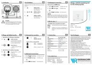
und Bedienungsanleitung für ABUS Fenster-Universalschloss FTS ...
und Bedienungsanleitung für ABUS Fenster-Universalschloss FTS ...
und Bedienungsanleitung für ABUS Fenster-Universalschloss FTS ...

Create successful ePaper yourself
Turn your PDF publications into a flip-book with our unique Google optimized e-Paper software.
Abb./fig.<br />
schéma<br />
afb./ill. 4a<br />
Abb./fig./schéma/afb./ill. 4b<br />
A<br />
Falzhöhe/Rebate height/Recouvrement/<br />
Opdekmaat/Altezza d’incassatura<br />
> 16 mm<br />
1<br />
2 mm<br />
4<br />
7<br />
Schlosskasten<br />
Lock case<br />
Boîtier<br />
Slotkast<br />
Casa<br />
7<br />
Rahmen<br />
Frame<br />
Cadre<br />
Kozijn<br />
Telaio<br />
Anschraubleiste<br />
Screw-on rail<br />
Socle de fixation<br />
Montageplaat<br />
Listello di montaggio<br />
2<br />
Tür/<strong>Fenster</strong><br />
Door/Window<br />
Fenêtre<br />
Deur/Raam<br />
Porta risp. Finestra<br />
<strong>ABUS</strong> - Das gute Gefühl der Sicherheit<br />
4<br />
Abb./fig./schéma/afb./ill. 5<br />
X mm<br />
Schließkasten<br />
Locking case<br />
Gâche<br />
Sluitkast<br />
Scatola<br />
D Technische Änderungen vorbehalten. Für Irrtümer <strong>und</strong> Druckfehler keine Haftung. <strong>ABUS</strong> © 2010<br />
G Subject to technical alterations. No liability for mistakes and printing errors. <strong>ABUS</strong> © 2010<br />
N<br />
N<br />
a<br />
b<br />
c<br />
d<br />
c<br />
b<br />
a<br />
1<br />
a<br />
a<br />
B<br />
Falzhöhe/Rebate height/<br />
Recouvrement/Opdekmaat/<br />
Altezza d’incassatura<br />
14 –16 mm<br />
2 mm<br />
D<br />
Falzhöhe/Rebate height/<br />
Recouvrement/Opdekmaat/<br />
Altezza d’incassatura<br />
1– 9 mm<br />
2 mm<br />
3<br />
2<br />
5<br />
6<br />
C<br />
Falzhöhe/Rebate height/<br />
Recouvrement/Opdekmaat/<br />
Altezza d’incassatura<br />
10 –13 mm<br />
2 mm<br />
E<br />
Falzhöhe/Rebate height/<br />
Recouvrement/Opdekmaat/<br />
Altezza d’incassatura<br />
0 mm<br />
2– 4 mm<br />
e<br />
f<br />
e<br />
D V. Montageanleitung:<br />
Wichtige Hinweise:<br />
1. Vor der Montage prüfen Sie bitte die Einstellung des <strong>Fenster</strong>s bzw.<br />
der <strong>Fenster</strong>tür. Stellen Sie sicher, dass sich das <strong>Fenster</strong>/die <strong>Fenster</strong>tür<br />
einwandfrei öffnen <strong>und</strong> schließen lässt.<br />
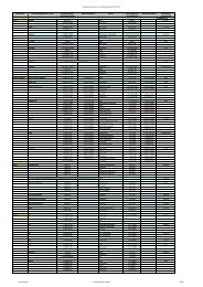
2. Messen Sie auch nach, ob die in Abb. 1 angegebenen Mindestmaße<br />
an Ihrem <strong>Fenster</strong>/Ihrer <strong>Fenster</strong>tür vorhanden sind.<br />
3. Die Bohrlochtiefen bzw. die Schraubenlängen müssen auf die<br />
örtlichen Gegebenheiten abgestimmt werden.<br />
4. Austreten des Bohrers bzw. der Schrauben auf der Rückseite vermeiden!<br />
Ggf. mit Bohranschlag arbeiten oder die vorhandenen<br />
Schrauben kürzen. Beim Bohren keine beweglichen Teile, Dichtungen<br />
oder Glasscheiben verletzen.<br />
Montage:<br />
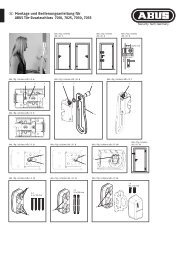
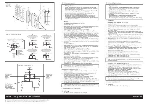
Montage des Schlosskastens (Abb. 4a + 4b)<br />
Falzhöhe ab 14 mm<br />
1. Abdeckplatten (5) des Schlosskastens (1) vorsichtig von unten ausstoßen.<br />
2. Anschraubleiste (4) in gewünschter Höhe 1 mm von der Türbzw.<br />
<strong>Fenster</strong>kante entfernt anhalten.<br />
3. Als Abstandshalter dünnste Unterlage (7) verwenden.<br />
Löcher „b“ (Abb. 4a) anzeichnen <strong>und</strong> vorbohren (s. Bohrtabelle).<br />
4. Anschraubleiste (4) ggf. mit Unterlagen (7) unterfüttern <strong>und</strong> mit Schrauben<br />
6,3 x 60 mm anschrauben, sodass sich die Fixiernocken „N“ (Abb. 4a)<br />
auf der zum <strong>Fenster</strong> abgewandten Seite befinden. Die Oberflächen der<br />
Anschraubleiste (4) <strong>und</strong> des <strong>Fenster</strong>flügels müssen auf einer Höhe liegen.<br />
5. Löcher „c“ durch die Anschraubleiste (4) hindurch schräg zum Mauerwerk<br />
hin bohren <strong>und</strong> Schrauben 6,3 x 60 mm eindrehen.<br />
6. Der eventuelle zusätzliche Einsatz von <strong>ABUS</strong> IM 100 oder <strong>ABUS</strong> BA erfolgt<br />
durch Loch „d“.<br />
7. Schlosskasten (1) mit Schrauben M6 x 35 mm auf der Anschraubleiste (4)<br />
befestigen.<br />
Falzstärke 1–13 mm<br />
1. Abdeckplatten (5) des Schlosskastens (1) vorsichtig von unten ausstoßen.<br />
2. Schlosskasten (1) in gewünschter Höhe 1 mm von der Tür- bzw. <strong>Fenster</strong>kante<br />
entfernt anhalten.<br />
3. Als Abstandshalter dünnste Unterlage (7) verwenden.<br />
4. Löcher „a“ anzeichnen <strong>und</strong> vorbohren (s. Bohrtabelle)<br />
(der eventuelle zusätzliche Einsatz von <strong>ABUS</strong> IM 100 oder <strong>ABUS</strong> BA erfolgt<br />
durch die Löcher „a“).<br />
5. Schlosskasten (1) mit Unterlagen (7) mit Schrauben 6,3 x 60 mm<br />
anschrauben.<br />
Falzstärke 0 mm (z.B. Schiebetür)<br />
1. Abdeckplatten (5) des Schlosskastens (1) vorsichtig von unten ausstoßen.<br />
2. Schlosskasten (1) mit dem Rahmen bündig abschließen lassen.<br />
3. Löcher „a“ anzeichnen <strong>und</strong> vorbohren (s. Bohrtabelle)<br />
(der eventuelle zusätzliche Einsatz von <strong>ABUS</strong> IM 100 oder <strong>ABUS</strong> BA erfolgt<br />
durch die Löcher „a“).<br />
4. Schlosskasten (1) mit Schrauben 6,3 x 60 mm anschrauben.<br />
Anmerkung: Bei Hebe-/Schiebetüren im abgesenkten Zustand<br />
2 Stück <strong>FTS</strong> 88 auf der Öffnungsseite montieren.<br />
Montage des Schließkastens (Abb. 5)<br />
1. Abdeckplatte (6) des Schließkastens (2) vorsichtig von unten durch die<br />
3 Löcher ausstoßen.<br />
2. Schließkasten (2) in gleicher Höhe des montierten Schlosskastens (1)<br />
im Abstand von 2 mm entfernt von diesem anhalten<br />
(bei Hebe-/Schiebetüren 2 bis max. 4 mm).<br />
Als Abstandshalter kann eine Unterlage (7) verwendet werden.<br />
3. Löcher „e“ anzeichnen <strong>und</strong> vorbohren (s. Bohrtabelle).<br />
4. Schließblech (3) gr<strong>und</strong>sätzlich in Schließkasten (2) einlegen (Abb. 4a).<br />
Schließkasten (2) mit Schrauben 4,8 x 25 oder 4,8 x 32 mm anschrauben.<br />
5. Loch „f“ durch den Schließkasten (2) hindurch schräg bohren <strong>und</strong><br />
Schraube 6,3 x 60 mm eindrehen.<br />
Funktion prüfen! Riegel müssen beim Einschließen in den Schließkasten<br />
<strong>und</strong> beim Heben <strong>und</strong> Senken der Hebe-Schiebetüren frei laufen.<br />
6. Abdeckungen (5 <strong>und</strong> 6) aufdrücken.<br />
VI. Bedienung<br />
<strong>FTS</strong> 88 wird mit dem Schlüssel ver- <strong>und</strong> entriegelt.<br />
G V. Assembling Instructions:<br />
Important notes:<br />
1. Prior to assembling, please check the adjustment of the window<br />
or French window. Make sure that the window/French window<br />
can be opened and closed correctly.<br />
2. Check that the min. dimensions shown in fig. 1 apply to your<br />
window or French window.<br />
3. The drill hole depths or screw lengths must be adjusted to local<br />
conditions.<br />
4. Avoid the drill bit or screws coming out on the rear sides!<br />
If necessary, use a bit stop or cut the screws to size.<br />
Do not damage any moving parts, seals or glass panes when drilling.<br />
Assembling:<br />
Assembling of the lock case (fig. 4a + 4b)<br />
Rebate > 14 mm<br />
1. Cautiously eject cover plates (5) of the lock case (1) from below.<br />
2. Hold screw-on rail (4) at desired height 1 mm away from door or window<br />
edge<br />
3. Use thinnest spacer (7) as spacer. Mark holes “b” (fig. 4a) and drill<br />
(see Drilling Table).<br />
4. Back screw-on rail (4) with spacers (7) if necessary and screw on using<br />
screws 6.3 x 60 mm. The surfaces of the screw-on rail (4) and the window<br />
wing must be flush.<br />
5. Drill holes “c” through the screw-on rail (4) at an angle with the masonry<br />
and screw in screws 6.3 x 60 mm.<br />
6. Possible additional use of <strong>ABUS</strong> IM 100 or <strong>ABUS</strong> BA through hole “d”.<br />
7. Fasten lock case (1) on the screw-on rail (4) with screws M6 x 35 mm.<br />
Rebate 1–13 mm<br />
1. Cautiously eject cover plates (5) of the lock case (1) from below.<br />
2. Hold lock case (1) at desired height 1 mm away from door or window<br />
edge.<br />
3. Use thinnest spacer (7) as guide plate to find the right distance.<br />
4. Mark holes “a” and drill (see Drilling Table).<br />
(Possible additional use of <strong>ABUS</strong> IM 100 or <strong>ABUS</strong> BA through holes “a”).<br />
5. Fasten lock case (1) with spacers (7) with screws 6.3 x 60 mm.<br />
Rebate 0 mm (e.g. sliding door)<br />
1. Cautiously eject cover plates (5) of the lock case (1) from below.<br />
2. Hold lock case (1) flush with frame.<br />
3. Mark holes “a” and drill (see Drilling Table) (Possible additional use<br />
of <strong>ABUS</strong> IM 100 or <strong>ABUS</strong> BA through hole “a”).<br />
4. Fasten lock case (1) with screws 6.3 x 60 mm.<br />
Note: For lifting/sliding doors, mount 2 x <strong>FTS</strong> 88 on the opening side<br />
in lowered condition.<br />
Assembling of the casing of the lock (fig. 5)<br />
1. Cautiously eject cover plate (6) of the casing of the lock (2) from below<br />
through the three holes.<br />
2. Hold casing of the lock (2) at height of the lock case mounted (1)<br />
at a distance of 2 mm from the lock case (2 to max. 4 mm for lifting/<br />
sliding doors). A spacer (7) can be used as spacer.<br />
3. Mark holes “e” and drill (see Drilling Table).<br />
4. Insert striking plate (3) into the casing of the lock (2) (fig. 4a).<br />
Fasten casing of the lock (2) with screws 4.8 x 25 or 4.8 x 32 mm.<br />
5. Drill hole “f” through casing of the lock (2) at an angle and screw in<br />
screw 63 x 60 mm.<br />
Check function! Bolts must run free when latching into the casing<br />
of the lock and when lifting or lowering the sliding door.<br />
6. Press on covers (5 and 6).<br />
VI. Operation<br />
The <strong>FTS</strong> 88 is locked/unlocked with the key.<br />
www.abus.com