Electric-System EVS 38/20-DS/IU - Calira
Electric-System EVS 38/20-DS/IU - Calira
Electric-System EVS 38/20-DS/IU - Calira

You also want an ePaper? Increase the reach of your titles
YUMPU automatically turns print PDFs into web optimized ePapers that Google loves.
Betriebsanleitung<br />
Operating Instructions<br />
Mode d´emploi<br />
<strong>Electric</strong>-<strong>System</strong><br />
<strong>EVS</strong> <strong>38</strong>/<strong>20</strong>-<strong>DS</strong>/<strong>IU</strong><br />
! "#$ %&&<br />
Lerchenfeldstr. 9 87600 Kaufbeuren Tel.: +49(0)8341 / 9764-0 Fax: +49(0)8341 / 67806
Vor Anschluss und Inbetriebnahme des Gerätes<br />
unbedingt die Betriebsanleitung lesen!<br />
Inhaltsverzeichnis<br />
Sicherheitshinweise........................................................3<br />
Verwendungszweck .......................................................3<br />
Beschreibung..................................................................4<br />
Sicherungen..............................................................5<br />
Ladevorgang Versorgungsbatterie............................6<br />
Ladevorgang Starterbatterie .....................................7<br />
12 Volt Ausgänge.....................................................8<br />
Technische Daten.........................................................10<br />
Ladekennlinie .........................................................11<br />
Montage .......................................................................12<br />
Aufstellen ...............................................................12<br />
Leitungslängen und Leitungsquerschnitte ....................14<br />
Anschluss<br />
Anschluss an die Bedientafel..................................14<br />
Anschluss an den Frischwassertank........................16<br />
Anschluss an den Abwassertank.............................16<br />
Temperaturfühler, Unschalter Batterie ...................16<br />
Anschluss 12-poliger Stecker .................................17<br />
Anschlussplan 12-poliger Stecker ..........................19<br />
Anschluss unterer Kabelbaum A01 ........................<strong>20</strong><br />
Anschluss oberer Kabelbaum A02 .........................<strong>20</strong><br />
Netzanschluss .........................................................<strong>20</strong><br />
Inbetriebnahme ............................................................21<br />
Wartungshinweise ........................................................22<br />
Maßnahmen bei Störungen.....................................23<br />
Instandsetzung........................................................24<br />
Garantie........................................................................24<br />
Stand: 28.10.<strong>20</strong>03<br />
Technische Änderungen vorbehalten<br />
2<br />
! "#$ %&&<br />
Lerchenfeldstr. 9 87600 Kaufbeuren Tel.: +49(0)8341 / 9764-0 Fax: +49(0)8341 / 67806
Allgemeine Sicherheitshinweise aufmerksam lesen!<br />
Achtung!<br />
Beim Gebrauch von elektrischen Geräten sind zum Schutz vor elektrischem<br />
Schlag, Verletzung und Brandgefahr folgende grundsätzliche<br />
Sicherheitsmaßnahmen zu beachten. Lesen und beachten Sie diese Hinweise,<br />
bevor Sie das Gerät benutzen.<br />
Aufstellen<br />
Achten Sie darauf, dass die Geräte sicher aufgestellt werden und nicht<br />
herabfallen oder umstürzen können. Legen Sie Leitungen stets so, dass keine<br />
Stolpergefahr entsteht. Setzen Sie Elektrogeräte nicht dem Regen aus.<br />
Betreiben Sie Elektrogeräte nicht in feuchter oder nasser Umgebung. Betreiben<br />
Sie Elektrogeräte nicht in der Nähe von brennbaren Flüssigkeiten oder Gasen.<br />
Stellen Sie Ihre elektrischen Geräte so auf, dass Kinder keinen Zugriff darauf<br />
haben.<br />
Schutz vor elektrischem Schlag<br />
Betreiben Sie nur Geräte deren Gehäuse und Leitungen unbeschädigt sind.<br />
Achten Sie auf sichere Verlegung der Kabel. Ziehen Sie nicht an den Kabeln.<br />
Achtung!<br />
Den elektrischen Anschluss der Geräte über einen Fehlerstromschutzschalter<br />
30 mA Nennfehlerstrom absichern und nur so betreiben. EVU-Vorschriften<br />
beachten.<br />
Gebrauch<br />
Benutzen Sie keine elektrischen Geräte entgegen dem, vom Hersteller<br />
angegebenen Verwendungszweck.<br />
Zubehör<br />
Benutzen Sie nur Zubehörteile und Zusatzgeräte die vom Hersteller geliefert<br />
oder empfohlen werden. Der Einsatz anderer Zubehöre birgt Gefahren.<br />
Verwendungszweck<br />
Die Elektroversorgung ist eine Kombination aus einem automatischen<br />
Ladegerät und einem Batterie-Trennautomaten. Sie dient der 12 Volt<br />
Stromverteilung und dem Laden von ausschließlich 12 Volt Bleiakkumulatoren,<br />
bestehend aus 6 Einzelzellen (z.B. Autobatterie), mit einer Kapazität von 70 -<br />
<strong>20</strong>0 Ah. Die Elektroversorgung ist universell einsetzbar und für Dauerbetrieb,<br />
Parallelbetrieb und Pufferbetrieb ausgelegt. Das bevorzugte Einsatzgebiet der<br />
! "#$ %&&<br />
3<br />
Lerchenfeldstr. 9 87600 Kaufbeuren Tel.: +49(0)8341 / 9764-0 Fax: +49(0)8341 / 67806
Elektroversorgung sind Batterien mit Gel- oder Flüssigelektrolyt.<br />
Die Elektroversorgung ist besonders für den Einsatz in Reisemobilen<br />
konzipiert. Die Elektroversorgung darf nur in trockenen Räumen betrieben<br />
werden.<br />
Bestimmungswidriger Gebrauch<br />
Nicht für 6 Volt Batterien, oder<br />
nichtaufladbare Batterien verwenden!<br />
Die Elektroversorgung darf nicht zum Laden von 6 Volt Bleiakkumulatoren<br />
verwendet werden. Werden Batterien mit einer Nennspannung von 6 Volt mit<br />
der Elektroversorgung geladen, so setzt die Gasung sofort ein. Es entsteht<br />
explosives Knallgas.<br />
Die Elektroversorgung darf nicht zum Laden von nichtaufladbaren Batterien<br />
und/oder Nickel-Cadmium-Batterien verwendet werden.<br />
Beim Laden dieser Batteriearten, mit der Elektroversorgung, kann die Hülle<br />
explosionsartig aufplatzen.<br />
Beschreibung<br />
Die Elektroversorgung ist ein Produkt modernster, Mikroprozessor gesteuerter<br />
Schaltnetzteiltechnik. Diese Technik ermöglicht hohe Leistung bei geringem<br />
Gewicht und kleinen Abmessungen. Durch Verwendung hochwertiger<br />
Elektronik arbeitet das Gerät mit einem hohen Wirkungsgrad. Das automatische<br />
Laden erfolgt schonend und ohne schädliches Überladen der Batterie. So wird<br />
die Lebensdauer der Batterie wesentlich verlängert. Nach Herstellen des<br />
Batterieanschlusses und des Netzanschlusses ist die Elektroversorgung in<br />
Betrieb.<br />
Die Elektroversorgung ist für Parallelbetrieb und Pufferbetrieb konzipiert.<br />
Verbraucher können ständig angeschlossen bleiben, dazugeschaltet oder<br />
weggeschaltet werden. Es werden gleichzeitig die Verbraucher versorgt und die<br />
Batterie geladen. Der Verbraucherstrom soll hierbei kleiner als der max.<br />
Ladestrom sein, da sonst keine Ladung der Batterie erfolgt.<br />
Wird die Elektroversorgung zusammen mit einem Temperaturfühler für die<br />
Versorgungsbatterie (Batterie II) betrieben, so regelt die Elektroversorgung die<br />
Ladespannung automatisch in Abhängigkeit der Batterietemperatur. Hierdurch<br />
4<br />
! "#$ %&&<br />
Lerchenfeldstr. 9 87600 Kaufbeuren Tel.: +49(0)8341 / 9764-0 Fax: +49(0)8341 / 67806
wird eine besonders effektive und schonende Ladung der Batterie erreicht.<br />
Ohne Verwendung eines Temperaturfühlers regelt die Elektroversorgung den<br />
Ladevorgang wie bei einer Batterietemperatur von <strong>20</strong>° C.<br />
Das Gerät ist für den Betrieb in einer Umgebungstemperatur bis 35° C<br />
ausgelegt. Steigt die Geräteinnentemperatur durch mangelnde Luftzirkulation<br />
oder zu hohe Umgebungstemperatur, so reduziert sich der Ladestrom<br />
automatisch stufenweise.<br />
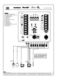
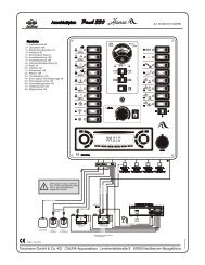
Bild 1<br />
Bild 2<br />
Verbraucherstromkreissicherungen 12 Volt<br />
Die Verbraucherstromkreissicherungen 12 Volt befinden<br />
sich gut zugänglich auf der Gehäuseoberseite. Es handelt<br />
sich um sechs Flachstecksicherungen, die mit Hilfe der<br />
mitgelieferten Sicherungsausziehzange leicht gewechselt<br />
werden können.<br />
Kühlschrank - Sicherungswert 15 A<br />
Dauerstrom für Heizung und Sofortlicht 7,5 A<br />
Abwassertankheizung - Sicherungswert 5 A<br />
Wasserpumpe - Sicherungswert 5 A<br />
Verbraucherstromkreis 2 - Sicherungswert 10 A<br />
Verbraucherstromkreis 1 - Sicherungswert 10 A<br />
Sicherungsautomat 230 Volt<br />
Der Sicherungsautomat für die 230 Volt Netzabsicherung<br />
befindet sich ebenfalls gut zugänglich auf der<br />
Gehäuseoberseite. Je nach Ausführung mit oder ohne<br />
Fehlerstromschutzschalter 30 mA.<br />
! "#$ %&&<br />
5<br />
Lerchenfeldstr. 9 87600 Kaufbeuren Tel.: +49(0)8341 / 9764-0 Fax: +49(0)8341 / 67806
Ladevorgang Versorgungsbatterie (Batterie II)<br />
Die Elektroversorgung besitzt einen elektronischen Verpolungsschutz. Nur<br />
wenn die Batterie richtig angeschlossen ist und eine Mindestspannung von 1,5<br />
Volt anliegt, wird der Ladestrom freigegeben. Während des Ladevorgangs wird<br />
die Batteriespannung ständig über die Messleitung B+ überwacht. Der<br />
Ladevorgang erfolgt gemäß der Ladekennlinie unter geringster Verlustleistung.<br />
(Ladekennlinie siehe Bild 5).<br />
Hauptladephase (alle Spannungswerte bezogen auf <strong>20</strong>° C Batterietemperatur)<br />
Ladung mit maximalem konstanten Ladestrom bis annähernd 14,4 Volt<br />
Batteriespannung erreicht sind. Sinkt in diesem Bereich der Hauptladephase<br />
der Ladestrom bedingt durch den Batterieinnenwiderstand und<br />
Leitungswiderstände unter 90% des Nennstromes ab, wird die Nachladephase<br />
gestartet.<br />
Nachladephase (alle Spannungswerte bezogen auf <strong>20</strong>° C Batterietemperatur)<br />
Die Ladespannung wird über eine Zeitdauer von zehn Stunden bei Gelbatterien<br />
bzw. vier Stunden bei Flüssigelektrolytbatterien konstant auf 14,4 Volt<br />
gehalten. Nach Ablauf dieser Zeit erfolgt eine Umschaltung in die<br />
Erhaltungsladephase. Steigt während dieser Zeit der Strom auf über 90% des<br />
Nennstromes und sinkt dabei die Batteriespannung für einen Zeitraum von<br />
mehr als 15 Minuten bei Flüssigelektrolytbatterien und mehr als zwei Stunden<br />
bei Gelbatterien unter 13,2 Volt, so erfolgt eine Umschaltung zurück in die<br />
Hauptladephase.<br />
Erhaltungsladephase (alle Spannungswerte bezogen auf <strong>20</strong>° C Batterietemperatur)<br />
Die Ladespannung ist auf 13,8 Volt eingestellt. Der Ladestrom sinkt dabei auf<br />
den für die Batterie zur Ausgleichsladung notwendigen Wert ab. Steigt der<br />
Ladestrom bedingt durch Verbraucher auf seinen Nennwert und sinkt die<br />
Batteriespannung für mindestens zwei Minuten unter 13,2 Volt so schaltet das<br />
Gerät wieder in die Hauptladephase zurück<br />
Parallelbetrieb<br />
Wird während der Nachladephase oder der Erhaltungsladephase<br />
Verbraucherstrom entnommen, so wird dieser sofort nachgeladen.<br />
Ladevorgang Starterbatterie (Batterie I)<br />
Parallelschaltung<br />
Fahrbetrieb<br />
Im Fahrbetrieb wird die Starterbatterie (Batterie I) von der Lichtmaschine des<br />
Kraftfahrzeuges geladen. Solange die Lichtmaschine läuft und Spannung am<br />
6<br />
! "#$ %&&<br />
Lerchenfeldstr. 9 87600 Kaufbeuren Tel.: +49(0)8341 / 9764-0 Fax: +49(0)8341 / 67806
Eingang D+ (Kontakt 18) der Elektroversorgungen anliegt, sind die<br />
Versorgungsbatterie und die Starterbatterie parallel geschaltet. Die<br />
Versorgungsbatterie wird von der Lichtmaschine mit geladen. Erhält die<br />
Elektroversorgung keine Spannung am D+ Eingang, so wird die<br />
Parallelschaltung bei unterschreiten einer Spannung von 13,2 Volt aufgehoben.<br />
Sollte es nicht möglich sein den D+ Steuerkontakt der Lichtmaschine<br />
abzugreifen, ist im Gerät eine Schaltautomatik integriert, welche die<br />
Parallelschaltung und Trennung der beiden Batterien in Abhängigkeit von der<br />
Spannung der Starterbatterie ausführt.<br />
Netzbetrieb (alle Spannungswerte bezogen auf <strong>20</strong>° C Batterietemperatur)<br />
Bei 230 Volt Netzanschluss wird die Versorgungsbatterie vorrangig geladen.<br />
Erreicht die Versorgungsbatterie die Spannung von 14,3 Volt, erfolgt die<br />
Parallelschaltung mit der Starterbatterie. Steigt der Ladestrom bedingt durch<br />
Verbraucher auf seinen Nennwert und sinkt die Batteriespannung unter 13,2<br />
Volt so wird die Parallelschaltung automatisch aufgehoben. Die Starterbatterie<br />
bleibt somit immer startfähig.<br />
Solarbetrieb<br />
Bei Anschluss externer Solarzellen wird die Starterbatterie mit geladen, wenn<br />
die Versorgungsbatterie eine Spannung von 14,3 Volt erreicht hat. Fällt die<br />
Spannung der Versorgungsbatterie unter 13,2 Volt ab, so wird die<br />
Parallelschaltung wieder aufgehoben.<br />
12 Volt Ausgänge<br />
Verbraucherstromkreis 1 (unterer Kabelbaum A01 Pin 1) und<br />
Verbraucherstromkreis 2 (oberer Kabelbaum A02 Pin 2)<br />
Die Ausgänge zu den Verbrauchern führen nur dann +12 Volt, wenn das<br />
bistabile Verbraucher-Relais durchgeschaltet hat. Das Verbraucher-Relais<br />
schaltet erst durch, wenn +12 Volt Steuerspannung am Pin Nr. 4 des 12-poligen<br />
Steckers anliegt. Die Verbraucherstromkreise sind mit je einer 10 A<br />
Sicherung abgesichert.<br />
Dauerstrom für Heizung und Sofortlicht (A01 Pin 4)<br />
Die Heizung und das Sofortlicht werden unabhängig vom Verbraucher-Relais<br />
versorgt. Sie sind am Dauerplus angeschlossen und mit einer 7,5 A Sicherung<br />
abgesichert.<br />
Wasserpumpe (A01 Pin 3)<br />
! "#$ %&&<br />
7<br />
Lerchenfeldstr. 9 87600 Kaufbeuren Tel.: +49(0)8341 / 9764-0 Fax: +49(0)8341 / 67806
Wenn der Hauptschalter, auf der Bedientafel eingeschaltet ist und der<br />
Wasserpumpenschalter in Stellung EIN steht, wird die Frischwasserpumpe über<br />
das Wasserpumpen-Relais versorgt. Die Steuerspannung für das<br />
Wasserpumpen-Relais ist am Pin 7 des 12-poligen Steckers angeschlossen. Der<br />
Stromkreis für die Wasserpumpe ist am Gerät mit einer 5 A Sicherung<br />
abgesichert.<br />
Kühlschrank<br />
Umschalter in Stellung Absorber (A01 Pin 5)<br />
Bild 3<br />
Bei laufendem Motor wird der Kühlschrank über die<br />
Lichtmaschine des Fahrzeuges versorgt. Das Kühlschrank-Relais<br />
trennt nach Abstellen des Motors den Kühlschrank von der<br />
Versorgungsbatterie. Die Ansteuerung erfolgt über die Leitung<br />
vom D+ der Lichtmaschine oder über die D+ Schaltautomatik.<br />
Ein Betrieb des Kühlschrankes mit 12 Volt ist somit nur während<br />
der Fahrt möglich. Bei Standpausen kann der Kühlschrank nur<br />
mit Gas oder Netzspannung betrieben werden. Eine Entleerung<br />
der Versorgungsbatterie, als auch der Starterbatterie ist somit<br />
ausgeschlossen. Dieser Stromkreis ist mit einer Sicherung von 15<br />
A abgesichert.<br />
Umschalter in Stellung Kompressor (A01 Pin 5)<br />
Bild 4<br />
Der Kühlschrank wird über Dauerplus versorgt, wenn der<br />
Hauptschalter auf der Bedientafel eingeschaltet ist.<br />
Abwassertankheizung (A01 Pin 15)<br />
Die Abwassertankheizung verhindert bei Minustemperaturen das Einfrieren des<br />
Abwassertanks. Die Steuerspannung für das Abwassertankheizungsrelais ist am<br />
Pin 8 des 12-poligen Steckers angeschlossen. Dieser Stromkreis ist mit einer 5<br />
A Sicherung abgesichert.<br />
8<br />
! "#$ %&&<br />
Lerchenfeldstr. 9 87600 Kaufbeuren Tel.: +49(0)8341 / 9764-0 Fax: +49(0)8341 / 67806
Technische Daten<br />
Stromversorgung Wechselspannung 230 V / 50 Hz, einphasig<br />
Bereich ca. 195 V - 265 V / 50 – 60 Hz.<br />
Ausgangsstrom:<br />
(Ladestrom Batterie II)<br />
Ausgangsstrom:<br />
(Ladestrom Batterie I)<br />
Ladestrom max. <strong>20</strong> A,<br />
arithmetischer Mittelwert, elektronisch geregelt<br />
entsprechend der Ladekennlinie .<br />
Ab 14,3 V Batteriespannung der Batterie II erfolgt die<br />
Parallelschaltung mit Batterie I. Ausgleichsstrom je nach<br />
Ladezustand der Batterie I (Starterbatterie). Fällt die<br />
Spannung der Batterie II unter 13,2 V ab, wird die<br />
Parallelschaltung automatisch aufgehoben.<br />
Ausgangsspannung: Gleichspannung 12 V<br />
Ladevorgang: Automatisch<br />
Schaltautomatik:<br />
(Hauptladephase)<br />
Schaltautomatik:<br />
(Nachladephase)<br />
Schaltautomatik:<br />
(Erhaltungsladephase)<br />
AUS bei Batteriespannung 14,4 V Ladestrom < 18 A,<br />
Zehn Stunden konstant 14,4 V bei Gelbatterien.<br />
Vier Stunden konstant 14,4 V bei Flüssigbatterien.<br />
Erhaltungsladung konstant 13,8 V.<br />
Schaltleistung: Tremat Trennrelais 50 A<br />
Kühlschrankrelais <strong>20</strong> A<br />
Verbraucherrelais 35 A<br />
Temperaturabhäng<br />
ige Regelung<br />
(optional)<br />
Die Werte der Schaltautomatik beziehen sich auf eine<br />
Batterietemperatur von <strong>20</strong>° C. Unter Verwendung eines<br />
Temperaturfühlers an der Batterie II variieren diese<br />
Werte in Abhängigkeit von der Batterietemperatur.<br />
Hohe Temperatur > Absenkung der Schwellwerte.<br />
Niedere Temperatur > höhergestellte Schwellwerte.<br />
Anwendung: Parallelbetrieb, Pufferbetrieb, allgemeiner Ladebetrieb<br />
! "#$ %&&<br />
9<br />
Lerchenfeldstr. 9 87600 Kaufbeuren Tel.: +49(0)8341 / 9764-0 Fax: +49(0)8341 / 67806
Temperatur: Umgebungstemperatur von –25° C bis +35° C. Bei<br />
Betrieb kann sich das Gehäuse auf ca. 75° C erwärmen.<br />
Kühlung: durch Konvektion<br />
Ausführung: Gemäß den Bestimmungen des VDE und des<br />
Gerätesicherheitsgesetzes.<br />
Aufbau gemäß:<br />
Prüfzeichen:<br />
Verwendung Zum Laden von Batterien mit 12 V Nennspannung und<br />
einer Kapazität von 70 - <strong>20</strong>0 Ah und zur 12 V<br />
Stromverteilung.<br />
Gehäuse: Aluminium, blank/rot lackiert, belüftet<br />
Länge:<br />
Breite:<br />
Höhe:<br />
302 mm (ohne Füße)<br />
173 mm (ohne Füße)<br />
145 mm<br />
Gewicht: 3,7 kg (37 N)<br />
Ladekennlinie<br />
HL =<br />
NL =<br />
EL =<br />
Hauptladephase<br />
Nachladephase<br />
Erhaltungsladephase<br />
Bild 5: Ladekennlinie (prinzipieller Verlauf)<br />
10<br />
! "#$ %&&<br />
Lerchenfeldstr. 9 87600 Kaufbeuren Tel.: +49(0)8341 / 9764-0 Fax: +49(0)8341 / 67806
Montage<br />
Sicherheitshinweise<br />
In diesem Gerät sind Bauteile eingebaut, die<br />
einen<br />
Funken oder Lichtbogen erzeugen können!<br />
Der Anschluss des Geräts an das Versorgungsnetzes muss in<br />
Übereinstimmung mit den jeweils geltenden nationalen<br />
Installationsvorschriften vorgenommen werden.<br />
Dieses Gerät beinhaltet Bauteile, die möglicherweise Lichtbögen und<br />
Funken erzeugen. Daher muss das Gerät, während es in einer Garage oder<br />
einem ähnlichen Ort betrieben wird, in einem für diesen Zweck<br />
vorgesehenen Raum oder Gehäuse untergebracht werden!<br />
Bei Verwendung des Gerätes in Reisemobilen, Wohnwagen und Booten<br />
müssen Gerät und die Batterie unbedingt in voneinander getrennten und gut<br />
belüfteten Boxen installiert werden!<br />
Die Montage und der Anschluss von elektrischen Geräten sollte<br />
grundsätzlich durch geeignetes Fachpersonal erfolgen!<br />
Stellen Sie sicher, dass die Stromzufuhr getrennt ist! Netzstecker ziehen!<br />
Benutzen Sie zum Anschluss des Gerätes nur die mitgelieferten Teile sowie<br />
die vorgeschriebenen Leitungsquerschnitte und Sicherungen!<br />
Benutzen Sie nur geeignetes und einwandfreies Werkzeug.<br />
Schließen Sie das Gerät nur gemäß des mitgelieferten Anschlussplanes an!<br />
Aufstellen<br />
Für die Erstausrüstung stehen verschiedene Beipacks zur Verfügung, die<br />
gesondert zu bestellen sind.<br />
Sonderzubehör (nicht im Beipack enthalten)<br />
Batterieschnellverbinder ”Quick Power” Best.Nr. H10 432 0110 00<br />
Temperaturfühler für Batterie II Best.Nr. H10 012 0003 00<br />
Das Gerät ist vor Feuchtigkeit und Nässe geschützt aufzustellen. Der<br />
Aufstellungsort muss sauber, trocken und gut belüftet sein. Bei Betrieb kann<br />
sich das Gehäuse auf ca. 75° C erwärmen. Halten sie daher einen<br />
! "#$ %&&<br />
11<br />
Lerchenfeldstr. 9 87600 Kaufbeuren Tel.: +49(0)8341 / 9764-0 Fax: +49(0)8341 / 67806
Mindestabstand von 100 mm ein und achten Sie darauf, dass die<br />
Lüftungsschlitze nicht verdeckt werden.<br />
Länge: 502 mm / Breite: 373 mm / Höhe: 245 mm<br />
Der für das Gerät bereitgestellte Raum darf oben stehende Abmessungen nicht<br />
unterschreiten, da der Mindestabstand von rundum 100 mm gewährleistet sein<br />
muss. Die separate Box für das Gerät muss oben und seitlich mit<br />
Lüftungsöffnungen versehen sein, die eine Gesamtöffnung von 10 000 mm²<br />
ergeben.<br />
Das Gerät möglichst in der Nähe der Batterie, aber unbedingt in separater<br />
Box aufstellen. Die Box für die Batterie muss mit einer Entlüftung nach außen<br />
versehen sein.<br />
Das Gerät mit den vier mitgelieferten Befestigungsschrauben sicher befestigen.<br />
Die Füße des Gerätes können um 90° gedreht werden. Hierzu müssen die<br />
Schrauben an den Füßen gelöst werden. Danach können die Füße gedreht und<br />
wieder fest verschraubt werden.<br />
Wichtig<br />
Achten sie darauf, dass die Lüftungsschlitze frei bleiben! Der Mindestabstand<br />
soll rundum 100 mm betragen! Unzureichende Belüftung kann zur Überhitzung<br />
des Gerätes führen! Das Gerät ist für den Betrieb in einer<br />
Umgebungstemperatur bis 35° C ausgelegt. Steigt die Geräteinnentemperatur<br />
durch mangelnde Luftzirkulation oder zu hohe Umgebungstemperatur, so<br />
reduziert sich der Ladestrom automatisch stufenweise.<br />
12<br />
! "#$ %&&<br />
Lerchenfeldstr. 9 87600 Kaufbeuren Tel.: +49(0)8341 / 9764-0 Fax: +49(0)8341 / 67806
Leitungslängen und Leitungsquerschnitte<br />
12-poliger Steckverbinder<br />
Batterie I Pluspol<br />
Ladestromleitung rot<br />
Batterie II Pluspol<br />
Ladestrom-<br />
/Versorgungsstromleitu<br />
ng rot<br />
Batterie II Minuspol<br />
Ladestrom- /Versorgungsstromleitung<br />
blau<br />
Anschluss<br />
Nur vorgeschriebene Leitungsquerschnitte<br />
verwenden!<br />
Länge bis 3 m Leitungsquerschnitt 10 mm².<br />
Länge bis 6 m Leitungsquerschnitt 10 mm².<br />
Länge über 6 m Leitungsquerschnitt 16 mm².<br />
Länge bis 6 m Leitungsquerschnitt 10 mm².<br />
Länge bis 6 m Leitungsquerschnitt 10 mm².<br />
Vor dem Anschließen / Trennen von Leitungen<br />
sind die Versorgungsleitungen von Batterie und<br />
Netz zu trennen!<br />
Anschluss an die Bedientafel<br />
12-poliger Flachstecker<br />
Schließen Sie das 12-polige Flachbandkabel an Ihrer Bedientafel an. Die<br />
Belegung der Kontakte finden Sie in der folgenden Aufstellung.<br />
Kontakt 1 Minusanschluss<br />
Kontakt 2 +Testanschluss für Batterie II<br />
Kontakt 3 +Testanschluss für Batterie I<br />
Bild 6: 12-poliger Stecker<br />
! "#$ %&&<br />
13<br />
Lerchenfeldstr. 9 87600 Kaufbeuren Tel.: +49(0)8341 / 9764-0 Fax: +49(0)8341 / 67806
Kontakt 4 Steueranschluss für Verbraucher-Relais<br />
Kontakt 5 Ausgang für Ladekontrolle<br />
Kontakt 6 Ausgang für Trematsignal<br />
Kontakt 7 Steueranschluss für Pumpen-Relais<br />
Kontakt 8 Steueranschluss für Abwassertankheizungs-Relais<br />
Stecken Sie das 12-polige Flachbandkabel in den vorgesehenen Anschluss am<br />
Gerät. Das Flachbandkabel lässt sich nur in der richtigen Position in den<br />
richtigen Anschluss am Gerät einführen. Wenden Sie keine Gewalt an.<br />
7-poliger Flachstecker<br />
Schließen Sie das 7-polige Flachbandkabel an Ihrer Bedientafel an. Die<br />
Belegung der Kontakte finden Sie in der folgenden Aufstellung.<br />
Kontakt 1 AW-Tank Com.<br />
Kontakt 2 AW-Tank ¾<br />
Kontakt 3 FW-Tank Com.<br />
Kontakt 4 FW-Tank ¼<br />
Kontakt 5 FW-Tank ½<br />
Kontakt 6 FW-Tank ¾<br />
Kontakt 7 FW-Tank 1/1<br />
Bild 7: 7-poliger Stecker<br />
Stecken Sie das 7-polige Flachbandkabel in den vorgesehenen Anschluss am<br />
Gerät. Das Flachbandkabel lässt sich nur in der richtigen Position in den<br />
richtigen Anschluss am Gerät einführen. Wenden Sie keine Gewalt an.<br />
14<br />
! "#$ %&&<br />
Lerchenfeldstr. 9 87600 Kaufbeuren Tel.: +49(0)8341 / 9764-0 Fax: +49(0)8341 / 67806
Anschluss an den Frischwassertank<br />
Schließen Sie das 5-polige Flachbandkabel an Ihrem Frischwassertank an. Die<br />
Belegung der Kontakte finden Sie in der folgenden Aufstellung.<br />
Bild 8: 5-poliger<br />
Stecker<br />
Kontakt 1 Com.<br />
Kontakt 2 1/4<br />
Kontakt 3 1/2<br />
Kontakt 4 3/4<br />
Kontakt 5 1/1<br />
Anschluss an den Abwassertank<br />
Schließen Sie das 2-polige Flachbandkabel an Ihrem Abwassertank an. Die<br />
Belegung der Kontakte finden Sie in der folgenden Aufstellung.<br />
Bild 9: 2-poliger<br />
Stecker<br />
Kontakt 1 Com.<br />
Kontakt 2 3/4<br />
Temperaturfühler, Umschalter Batterietyp<br />
Bild 10<br />
Falls Sie einen Temperaturfühler für die Batterie II<br />
verwenden, bringen Sie den Temperaturfühler an der<br />
Stirnseite der Batterie II (Versorgungsbatterie) an. Hierzu<br />
entfernen Sie die Schutzfolie vom Klettband der<br />
Temperaturfühlerbefestigung und drücken dieses kräftig<br />
auf die gewünschte Position an der Batterie II (siehe<br />
Beschreibung Temperaturfühler). Stecken Sie das Kabel<br />
des Temperaturfühlers an den Temperaturfühleranschluss<br />
(Bild 10, 2-poliger Anschluss) des Gerätes an.<br />
! "#$ %&&<br />
15<br />
Lerchenfeldstr. 9 87600 Kaufbeuren Tel.: +49(0)8341 / 9764-0 Fax: +49(0)8341 / 67806
Bild 11<br />
Anschluss 12-poliger Stecker<br />
Bild 12<br />
Bild 13<br />
Im Auslieferzustand ist das Gerät auf den Betrieb mit<br />
Flüssigelektrolytbatterien eingestellt. Stellen Sie bei<br />
Einsatz einer Gelbatterie den Umschalter (Bild 11) auf<br />
die Stellung "Gel" um.<br />
Schließen Sie die Kabel des 12-poligen Steckverbinders<br />
(Bild 12) laut Anschlussplan (Bild 17) an die<br />
Versorgungsbatterie (Batterie II), und die Starterbatterie<br />
(Batterie I) an.<br />
Achten Sie darauf, dass die Kontaktstifte sicher im<br />
Steckverbinder einrasten! Lose Kontaktstifte können zu<br />
Fehlfunktionen oder zum Kurzschluss führen.<br />
Die Minusleitung für die Batterie II (blau 10 mm²) an die<br />
Kontakte 24 und 25 am Gerät und die Minusklemme<br />
(Käfigzugfederklemme Bild 13) am Gerät und den<br />
Minuspol der Batterie II anschließen.<br />
Handhabung der Käfigzugfederklemmen<br />
Bereiten Sie das Anschlusskabel vor. Das Kabelende<br />
muss auf 11 mm abisoliert sein. Aderendhülsen sind nicht<br />
erforderlich.<br />
Folgende Abbildungen zeigen die grundsätzliche<br />
Handhabung von Käfigzugfederklemmen, die im Gerät<br />
eingebaute Version kann äußerlich von den<br />
Abbildungen abweichen, die grundsätzliche<br />
Handhabung bleibt aber gleich.<br />
Die Käfigzugfederklemme kann mit Hilfe eines passenden<br />
Flachschraubendrehers geöffnet werden.<br />
Führen Sie hierzu den Flachschraubendreher in die quadratische Öffnung (Bild<br />
14) und drücken Sie die Käfigzugfederklemme auf (Bild 15). Der Klemmteil<br />
der Feder in der runden Öffnung schwenkt dabei auf.<br />
Führen Sie das Kabel bis zur Isolierung in die Käfigzugfederklemme (runde<br />
Öffnung, Bild 15) ein und ziehen Sie den Flachschraubendreher heraus (Bild<br />
16<br />
! "#$ %&&<br />
Lerchenfeldstr. 9 87600 Kaufbeuren Tel.: +49(0)8341 / 9764-0 Fax: +49(0)8341 / 67806
16). Die Käfigzugfederklemme schließt sich wieder und das Kabel ist sicher<br />
geklemmt.<br />
Achten Sie darauf, dass die Kabelenden fest in den Käfigzugfederklemmen<br />
sitzen!<br />
Bild 14 Bild 15 Bild 16<br />
Käfigzugfederklemme Flachschraubendreher Kabel<br />
Die Plusleitung Batterie II (rot 10 mm²) an die Kontakte 16, 17, 19, <strong>20</strong>, 21 und<br />
22 am Gerät (Bild 17) und den Pluspol der Batterie II anschließen. Diese<br />
Leitung ist unbedingt, nahe dem Pluspol der Batterie II, mit einer 40 A<br />
Sicherung abzusichern!<br />
Die Plusleitung der Batterie I (rot 10 mm²) an die Kontakte 26 und 27 am Gerät<br />
(Bild 17) und den Pluspol der Batterie I anschließen. Diese Leitung ist<br />
unbedingt, nahe dem Pluspol der Batterie I, mit einer 40 A Sicherung<br />
abzusichern!<br />
! "#$ %&&<br />
17<br />
Lerchenfeldstr. 9 87600 Kaufbeuren Tel.: +49(0)8341 / 9764-0 Fax: +49(0)8341 / 67806
Anschlussplan 12-poliger Stecker<br />
- $ .&<br />
" / 0<br />
Nur vorgeschriebene Leitungsquerschnitte und<br />
Sicherungsstärken verwenden! Sicherungen<br />
unbedingt nahe der Pluspole der Batterien<br />
anbringen!<br />
+ ! "#<br />
$ %&"<br />
'" $<br />
( " *<br />
'" $<br />
() *<br />
18<br />
! "#$ %&&<br />
Lerchenfeldstr. 9 87600 Kaufbeuren Tel.: +49(0)8341 / 9764-0 Fax: +49(0)8341 / 67806<br />
+,,<br />
Bild 17: Anschlussplan 12-poliger Stecker<br />
** Diese Sicherungen sind unbedingt erforderlich!<br />
Bei Leitungslängen über 3 m siehe Tabelle Leitungslängen und<br />
Leitungsquerschnitte auf Seite 14.<br />
+,,
Anschluss unterer Kabelbaum A01<br />
Bild 18<br />
Anschluss oberer Kabelbaum A02<br />
Bild 19<br />
Netzanschluss<br />
Der untere Kabelbaum wird am 15poligen Stecker<br />
A01 an die <strong>EVS</strong> angeschlossen.<br />
Der obere Kabelbaum wird am 12poligen Stecker<br />
A02 an die <strong>EVS</strong> angeschlossen.<br />
Vor dem Anschließen / Trennen von Leitungen<br />
sind die Versorgungsleitungen von Batterie und<br />
Netz zu trennen!<br />
Stellen Sie den Potentialausgleich zwischen dem Gerät und dem Reisemobiles<br />
oder Caravan her. Verwenden Sie eine grün/gelbe Leitung mit einem<br />
Mindestquerschnitt von 4 mm². Der Potentialausgleich ersetzt nicht den<br />
Schutzleiter am Netzanschluss.<br />
1 $"& 2 "&$3" $<br />
5 & 6 !<br />
Bild <strong>20</strong>: Potentialausgleich<br />
Schließen Sie die 230 Volt Ausgänge der<br />
Elektroversorgung an die Netzverteilung Ihres<br />
Reisemobiles oder Caravans an. Grün/gelbe Leitung an<br />
Schutzerde! Der 230 Volt Sicherungsautomat der<br />
Elektroversorgung dient der Netzabsicherung und wird<br />
direkt, eingangsseitig an der Einspeisesteckdose Ihres<br />
Reisemobiles oder Caravans angeschlossen.<br />
! "#$ %&&<br />
19<br />
Lerchenfeldstr. 9 87600 Kaufbeuren Tel.: +49(0)8341 / 9764-0 Fax: +49(0)8341 / 67806<br />
4
Bild 21: Netzanschluss<br />
Inbetriebnahme<br />
Prüfen Sie alle Anschlüsse auf sicheren Sitz. Stellen Sie<br />
als Letztes die Netzverbindung über den Buchsenstecker<br />
des Netzkabels her. Die Buchse am Gerät ist mit einer<br />
Verriegelung versehen. Achten Sie beim Anschluss des<br />
Steckers darauf, dass die Verriegelung einrastet. Zum<br />
Abziehen des Steckers muss die Verriegelung, durch<br />
leichtes Anheben des Bügels, entriegelt werden.<br />
Die Elektroversorgung ist in Betrieb sobald die Netzverbindung hergestellt ist.<br />
Vor dem Unterbrechen oder Schließen von Gleichstromverbindungen, z.B.<br />
Ladestromkabel an der Batterie, ist das Gerät netzseitig abzuschalten.<br />
Netzstecker ziehen.<br />
Keinesfalls Batterien mit Zellenschluss laden!<br />
Laden einer Batterie<br />
Wird geladen, obwohl die Batterie einen Zellenschluss hat, oder die<br />
Ladeautomatik außer Betrieb ist, werden explosive Gase (Knallgas) freigesetzt.<br />
Sorgen Sie daher im Batterieraum für ausreichend Außenbelüftung. Vermeiden<br />
Sie Funken und offene Flammen!<br />
Voraussetzungen<br />
Die Batterie muss 12 Volt Nennspannung und eine Mindestkapazität von 70 Ah<br />
haben. Batterien unter dieser Mindestkapazität werden nur unzureichend<br />
geladen. Batterien mit einer zu hohen Kapazität werden zu langsam geladen.<br />
Achtung<br />
Batterien mit Zellenschluss dürfen nicht geladen werden. Explosionsgefahr<br />
durch Knallgasentwicklung!<br />
Ladevorgang<br />
Das Laden der Batterie erfolgt automatisch. Nach zwischenzeitlichem<br />
Netzausfall wird automatisch die Hauptladephase neu gestartet. Die<br />
Hauptladephase wird beendet, wenn die Batteriespannung 14,4 Volt erreicht.<br />
Nach Ablauf der Nachladephase erfolgt die Umschaltung auf<br />
Erhaltungsladephase von konstant 13,8 Volt.<br />
<strong>20</strong><br />
! "#$ %&&<br />
Lerchenfeldstr. 9 87600 Kaufbeuren Tel.: +49(0)8341 / 9764-0 Fax: +49(0)8341 / 67806
Parallelbetrieb<br />
Bei Parallelbetrieb soll der Verbraucherstrom kleiner als der maximale<br />
Ladestrom von <strong>20</strong> A sein. Nur so ist sichergestellt, dass die Batterie aufgeladen<br />
wird, obwohl Verbraucher versorgt werden.<br />
Wartungshinweise<br />
Vor allen Wartungsarbeiten am Gerät ist<br />
unbedingt die Stromzufuhr zu unterbrechen!<br />
Reinigen Sie das Gerät und die Lüftungsschlitze mit einem trockenen,<br />
fusselfreien Tuch.<br />
Maßnahmen bei Störungen<br />
Das Gerät ist wartungsfrei. Sollten dennoch Unregelmäßigkeiten auftreten,<br />
! "#$ %&&<br />
21<br />
Lerchenfeldstr. 9 87600 Kaufbeuren Tel.: +49(0)8341 / 9764-0 Fax: +49(0)8341 / 67806
gehen Sie bitte wie folgt vor.<br />
Störung Maßnahme<br />
Die Batterie wird<br />
nicht geladen.<br />
Die Spannung der<br />
Batterie ist unter<br />
1,5 Volt gesunken.<br />
Die Batterie II<br />
wird im<br />
Fahrbetrieb nicht<br />
geladen.<br />
Der maximale<br />
Ladestrom wird<br />
nicht erreicht.<br />
Sie können keine<br />
der hier<br />
beschriebenen<br />
Störungen<br />
feststellen. Das<br />
Gerät arbeitet<br />
dennoch nicht.<br />
Instandsetzung<br />
Prüfen Sie alle Anschlüsse von der Elektroversorgung zur<br />
Batterie, achten Sie dabei auf die richtige Polung. Stecken<br />
Sie den Netzstecker am Gerät aus und wieder ein. Prüfen<br />
Sie die Sicherungen und den Netzanschluss.<br />
Starten Sie den Motor und lassen Sie ihn ca. 30 Sekunden<br />
laufen. Die Batteriespannung steigt über 1,5 Volt. Der<br />
Ladevorgang beginnt selbständig.<br />
Prüfen Sie die Sicherungen.<br />
Das Gerät wird zu warm, sorgen Sie für bessere<br />
Belüftung des Gerätes.<br />
Wenden Sie sich direkt an den Hersteller:<br />
Trautmann GmbH & Co. KG<br />
CALIRA-Apparatebau<br />
Lerchenfeldstr. 9<br />
87600 Kaufbeuren<br />
Servicetelefon: 0190 / 77 03 80<br />
Homepage:<br />
E-Mail: info@calira.de<br />
(1,24 /min)<br />
Nehmen Sie keine Instandsetzungsarbeiten<br />
oder Veränderungen an dem Gerät vor!<br />
22<br />
! "#$ %&&<br />
Lerchenfeldstr. 9 87600 Kaufbeuren Tel.: +49(0)8341 / 9764-0 Fax: +49(0)8341 / 67806
Ein defektes Gerät kann nur durch den Hersteller oder dessen Service instand<br />
gesetzt werden. Beachten Sie hier die allgemeinen Sicherheitsbestimmungen.<br />
Garantie<br />
Garantie wird in dem Zeitraum von zwei Jahren ab Kaufdatum gewährt.<br />
Mängel infolge Material- oder Fertigungsfehler werden kostenlos beseitigt<br />
wenn:<br />
Das Gerät dem Hersteller kostenfrei zugesandt wird.<br />
Der Kaufbeleg beiliegt<br />
Das Gerät bestimmungsgemäß behandelt und verwendet wurde.<br />
Keine fremden Ersatzteile eingebaut oder Eingriffe vorgenommen wurden.<br />
Nicht unter die Garantie fallen Folgekosten und natürliche Abnützung.<br />
Wichtig<br />
Bei Geltendmachung von Ansprüchen aus Garantie und Gewährleistung ist<br />
eine ausführliche Beschreibung des Mangels unerlässlich. Detaillierte Hinweise<br />
erleichtern und beschleunigen die Bearbeitung. Bitte haben Sie Verständnis<br />
dafür, dass wir Sendungen, die uns unfrei zugehen, nicht annehmen können.<br />
! "#$ %&&<br />
23<br />
Lerchenfeldstr. 9 87600 Kaufbeuren Tel.: +49(0)8341 / 9764-0 Fax: +49(0)8341 / 67806
Table of contents<br />
' & "<br />
It is essential that you read the operating<br />
instructions before connecting and<br />
commissioning the device!<br />
Safety instructions........................................................27<br />
Purpose ........................................................................27<br />
Description...................................................................28<br />
Fuses.......................................................................29<br />
Supply battery charging procedure.........................30<br />
Starter battery charging procedure .........................30<br />
12 volt outputs........................................................31<br />
Technical data..............................................................33<br />
Charging characteristic curve .................................34<br />
Assembly......................................................................35<br />
Setting up................................................................35<br />
Cable lengths and cross-sections..................................37<br />
Connection<br />
Connection to the control panel..............................37<br />
Connection to the fresh water tank .........................39<br />
Connection to the waste water tank ........................39<br />
Temperature sensor, battery changeover switch.....39<br />
Connection of the 12-pole connector......................40<br />
Connection diagram of the 12-pole connector........42<br />
Connection of lower wiring loom A01 ...................43<br />
Connection of upper wiring loom A02 ...................43<br />
Mains connection ...................................................43<br />
Commissioning ............................................................44<br />
Maintenance instructions .............................................45<br />
Procedures in the event of faults.............................46<br />
Repairs....................................................................47<br />
Warranty ......................................................................47<br />
Version: 28.10.<strong>20</strong>03<br />
The right to make technical modifications is reserved.<br />
24<br />
! "#$ %&&<br />
Lerchenfeldstr. 9 87600 Kaufbeuren Tel.: +49(0)8341 / 9764-0 Fax: +49(0)8341 / 67806
' & "<br />
Please read general safety information carefully!<br />
Attention!<br />
The following important safety instructions must be observed when using<br />
electric devices, as protection against electric shock, injury and fire hazard.<br />
Please read and follow these instructions before using the device.<br />
Setting up<br />
Please ensure that the device is placed securely and cannot fall down or tip<br />
over. Always position cables so that nobody can trip over them. Do not expose<br />
electric devices to rain. Do not operate electric devices in a damp or humid<br />
environment. Do not operate electric devices in the vicinity of flammable<br />
liquids or gases. Place electric devices so that children do not have access to<br />
them.<br />
Protection against electric shock<br />
Only operate devices whose housing and cables are undamaged. Ensure safe<br />
cable positioning. Do not pull cables.<br />
Attention!<br />
Safeguard the electric connection of the devices with a 30 mA-rated leakage<br />
current circuit breaker, and only operate it with this protection. Observe the<br />
power supply companies regulations.<br />
Use<br />
Do not use electric devices other than for the purpose specified by the<br />
manufacturer.<br />
Accessories<br />
Only use accessories and supplementary devices supplied or recommended by<br />
the manufacturer. Using other accessories is hazardous.<br />
Purpose<br />
The power supply is a combination of an automatic charger and an automatic<br />
battery separator. It serves for the 12 volt current distribution and for the<br />
charging of exclusively 12 V lead batteries consisting of 6 separate cells (e.g.<br />
car battery) with a capacity of 70 - <strong>20</strong>0 Ah. The power supply is universally<br />
usable and is designed for permanent operation, parallel operation and buffer<br />
operation. The preferred application of the power supply are batteries with gel<br />
or a liquid electrolyte.<br />
The power supply is particularly suitable for the use in mobile homes. The<br />
! "#$ %&&<br />
25<br />
Lerchenfeldstr. 9 87600 Kaufbeuren Tel.: +49(0)8341 / 9764-0 Fax: +49(0)8341 / 67806
' & "<br />
power supply must only be operated in dry spaces.<br />
Inappropriate use<br />
Do not use with 6 volt batteries or<br />
with non-rechargeable batteries!<br />
The power supply must not be used to charge 6 volt lead batteries. If batteries<br />
with a rated voltage of 6 volt are charged with the power supply, gas is created<br />
immediately. Explosive oxyhydrogen gas is generated.<br />
The power supply must not be used to charge non-rechargeable batteries and/or<br />
nickel-cadmium batteries.<br />
When charging these battery types with the power supply, the outer cover may<br />
rupture explosively.<br />
Description<br />
The power supply is a product of up-to-date , microprocessor-controlled<br />
switched-mode power supply technology. This technology permits high output<br />
together with low weight and small dimensions. By using high-quality<br />
electronics, the device operates with high efficiency. Automatic charging<br />
affords protection and prevents harmful battery overload. This considerably<br />
extends the life of the battery. Once connected to the battery and the mains, the<br />
power supply is ready for operation.<br />
The power supply is designed for parallel operation and buffer operation. At all<br />
times, consumers can remain connected, be added or switched off. Consumers<br />
are supplied with the power and the battery is charged at the same time.<br />
Consumer current should be lower than the maximum charging current,<br />
otherwise the battery will not be charged.<br />
If the power supply is operated together with a temperature sensor for the<br />
supply battery (battery II), the power supply controls the charging voltage<br />
automatically depending on the battery temperature. This ensures a particularly<br />
effective and gently charging process for the battery. When not using a<br />
temperature sensor, the power supply controls the charging process as if the<br />
battery temperature was <strong>20</strong>° C.<br />
The device is designed for operation in ambient temperatures of up to 35° C. If<br />
the temperature inside the device rises due to a lack of air circulation or due to<br />
26<br />
! "#$ %&&<br />
Lerchenfeldstr. 9 87600 Kaufbeuren Tel.: +49(0)8341 / 9764-0 Fax: +49(0)8341 / 67806
' & "<br />
high ambient temperature, the charging current is automatically reduced in<br />
steps.<br />
Fig. 1<br />
Fig. 2<br />
12 volt user circuit fuses<br />
The 12 volt user circuit fuses are easily accessible on the<br />
upper side of the housing. There are six flat plug-in fuses<br />
that are easily exchanged with the aid of the fuse<br />
extraction pliers supplied.<br />
Fridge – 15 A fuse<br />
Permanent current for heating and immediate light 7.5 A<br />
Waste water tank heater – 5 A fuse<br />
Water pump – 5 A fuse<br />
User circuit 2 – 10 A fuse<br />
User circuit 1 – 10 A fuse<br />
Circuit breaker 230 volt<br />
The circuit breaker for the 230 volt mains protection is<br />
also easily accessible on the upper side of the housing.<br />
Each according to implementation with or without 30 mA<br />
differential circuit breaker.<br />
Supply battery charging procedure (battery II)<br />
The power supply has electronic protection against polarity inversion. The<br />
! "#$ %&&<br />
27<br />
Lerchenfeldstr. 9 87600 Kaufbeuren Tel.: +49(0)8341 / 9764-0 Fax: +49(0)8341 / 67806
' & "<br />
charging current is only released once the battery is correctly connected and a<br />
minimum voltage of 1.5 volt is applied. During the charging process, the<br />
battery voltage is constantly being monitored through the measuring cable B+.<br />
The charging process follows the charging characteristic curve, with minimal<br />
energy loss (for the charging characteristic curve, Fig. 5).<br />
Main charging phase (all voltage values with respect to a battery temperature of <strong>20</strong> °C)<br />
Charging with maximum constant charging current until the battery reaches<br />
14.4 volt. If the charging current drops below 90 % of the rated current during<br />
this phase due to the internal resistance of the battery and cable resistance, the<br />
post charging phase is started.<br />
Post charging phase (all voltage values with respect to a battery temperature of <strong>20</strong> °C)<br />
The charging voltage is kept constant at 14.4 volt for ten or four hours for gel<br />
batteries and liquid electrolyte batteries, respectively. After this time, the<br />
device switches to the charge phase. If during this phase the current rises above<br />
90 % of the rated current while the battery voltage drops below 13.2 volt for a<br />
period of 15 minutes for liquid electrolyte batteries, or for more than two hours<br />
for gel batteries, then the device switches back to the main charging phase.<br />
Holding charge phase (all voltage values with respect to a battery temperature of <strong>20</strong> °C)<br />
The charging voltage is set to 13.8 volt. At the same time, the charging current<br />
drops to the value necessary for the equalising charge of the battery. If the<br />
charging current rises to its rated value due to a user and the battery voltage<br />
remains below 13.2 volt for at least two minutes, then the device switches back<br />
to the main charging phase.<br />
Parallel operation<br />
If during the post charging or holding charge phase, current is consumed, it is<br />
recharged immediately.<br />
Starter battery charging procedure (battery I)<br />
Parallel circuit<br />
Driving operation<br />
During driving operation, the starter battery (battery I) is charged by the<br />
generator of the vehicle. As long as the generator is running and there is a<br />
voltage on the input D+ (contact 18) of the power supply, the supply battery<br />
and the starter battery are in parallel operation. The supply battery is also<br />
charged by the generator. If there is no voltage at the D+ input of the power<br />
supply, the parallel connection is turned off if the voltage falls below 13.2 volt.<br />
28<br />
! "#$ %&&<br />
Lerchenfeldstr. 9 87600 Kaufbeuren Tel.: +49(0)8341 / 9764-0 Fax: +49(0)8341 / 67806
' & "<br />
If it is not possible to reach the D+ control contact of the generator, an<br />
automatic switch is integrated in the device, which establishes and separates the<br />
parallel connection of the two batteries as a function of the voltage of the<br />
starter battery.<br />
Mains operation (all voltage values with respect to a battery temperature of <strong>20</strong> °C)<br />
When connecting to the mains of 230 volt, the supply battery is charged first.<br />
Once the supply battery reaches a voltage of 14.3 volt, it is switched in parallel<br />
with the starter battery. If the charging current rises to its rated value due to a<br />
user and the battery voltage falls below 13.2 volt, then the parallel connection<br />
is automatically disconnected. The starter battery thus always remains ready to<br />
start.<br />
Solar operation<br />
When connecting external solar cells, the starter battery is also charged<br />
provided that the voltage of the supply battery has reached 14.3 volt. If the<br />
voltage of the supply battery drops below 13.2 volt, the parallel circuit is<br />
disconnected again.<br />
12 volt outputs<br />
User circuit 1 (lower wiring loom A01 Pin 1) and<br />
User circuit 2 (upper wiring loom A02 Pin 2)<br />
The outputs to the users only carry +12 volt if the bistable user relay has<br />
switched on. The user relay only switches on if +12 volt control voltage is<br />
applied to pin no. 4 of the 12-pole plug. The user circuits are each protected by<br />
a 10 A fuse.<br />
Permanent current for heating and immediate light (A01 pin 4)<br />
Heating and immediate light are supplied independently of the user relay. They<br />
are connected to the permanent positive and protected with a 7.5 A fuse.<br />
Water pump (A01 pin 3)<br />
When the main switch on the control board is switched on and the water pump<br />
switch is in the ON position, the fresh water pump will be supplied by the<br />
water pump relay. The control voltage for the water pump relay is connected to<br />
pin 7 of the 12 pole plug. The circuit for the water pump is protected with a<br />
5 A fuse on the unit.<br />
Refrigerator<br />
Changeover switch to position Absorber (A01 pin 5)<br />
! "#$ %&&<br />
29<br />
Lerchenfeldstr. 9 87600 Kaufbeuren Tel.: +49(0)8341 / 9764-0 Fax: +49(0)8341 / 67806
Fig. 3<br />
' & "<br />
When the engine is running, the refrigerator is supplied with<br />
power via the generator of the vehicle. After the engine is<br />
switched off, the refrigerator relay disconnects the refrigerator<br />
from the supply battery. The control action is via the cable from<br />
the D+ of the generator or via the D+ of the automatic switching.<br />
Thus, operating the refrigerator at 12 volt is only possible during<br />
journeys. When the vehicle is parked, the refrigerator can only<br />
be run on gas or mains voltage. This prevents the supply battery<br />
as well as the starter battery from running down. This circuit is<br />
protected by a 15 A fuse.<br />
Changeover switch to position Compressor (A01 pin 5)<br />
Fig. 4<br />
The refrigerator is supplied via the permanent positive when the<br />
main switch is turned on at the control panel.<br />
Waste water tank heating (A01 pin 15)<br />
The waste water tank heating prevents the freezing of the waste water tank at<br />
below freezing temperatures. The control voltage for the waste water tank<br />
heating relay is connected to pin 8 of the 12 pole plug. This circuit is protected<br />
by a 5 A fuse.<br />
30<br />
! "#$ %&&<br />
Lerchenfeldstr. 9 87600 Kaufbeuren Tel.: +49(0)8341 / 9764-0 Fax: +49(0)8341 / 67806
Technical data<br />
' & "<br />
Power supply Alternating voltage 230 V / 50 Hz, single phase<br />
Range approx. 195 V - 265 V / 50 – 60 Hz.<br />
Output current:<br />
(Charging current for<br />
battery II)<br />
Output current:<br />
(Charging current for<br />
battery I)<br />
Output voltage: Direct voltage 12 V<br />
Charging process: Automatic<br />
Automatic<br />
switching:<br />
(Main charging phase)<br />
Automatic<br />
switching:<br />
(Post charging phase)<br />
Automatic<br />
switching:<br />
(Holding charge phase)<br />
Switching<br />
capacity:<br />
Temperature<br />
dependent control<br />
(optional)<br />
Charging current max. <strong>20</strong> A,<br />
arithmetic average, electronically regulated according to<br />
the charging characteristic curve <strong>IU</strong>oU.<br />
When the battery potential of battery II reaches 14.3 V, a<br />
parallel connection is established with battery I.<br />
Compensating current dependent on the charge state of<br />
battery I (starter battery). If the voltage of the battery II<br />
drops below 13.2 V, the parallel circuit is automatically<br />
disconnected.<br />
OFF when battery voltage reached 14.4 V, charging<br />
current < 18 A<br />
Ten hours constant 14.4 V in the case of gel batteries.<br />
Four hours constant 14.4 V in the case of liquid batteries.<br />
Holding charge, constant at 13.8 V.<br />
Tremat isolating relay: 50 A<br />
Refrigerator relay: <strong>20</strong> A<br />
User relay: 35 A<br />
The values of the automatic switching refer to a battery<br />
temperature of <strong>20</strong> °C. When using a temperature sensor at<br />
the battery II, these values vary as a function of the<br />
battery temperature.<br />
High temperature > Lowering of the threshold values.<br />
Low temperature > higher threshold values.<br />
Application: Parallel operation, buffer operation, general charging<br />
operation<br />
! "#$ %&&<br />
31<br />
Lerchenfeldstr. 9 87600 Kaufbeuren Tel.: +49(0)8341 / 9764-0 Fax: +49(0)8341 / 67806
' & "<br />
Temperature: Ambient temperature of –25 °C to +35 °C. During<br />
operation, the housing may heat up to approx. 75 °C.<br />
Cooling: By convection<br />
Implementation: According to Association of German Electrotechnical<br />
Engineers regulations and the provisions of the<br />
Instrument Safety Act.<br />
Design according<br />
to:<br />
Test labelling:<br />
Use For charging batteries with a rated voltage 12 V and a<br />
capacity of 70-<strong>20</strong>0 Ah and for 12 V current distribution.<br />
Housing: Aluminium, bright/painted red, ventilated<br />
Length:<br />
Width:<br />
Height:<br />
302 mm (without legs)<br />
173 mm (without legs)<br />
145 mm<br />
Weight: 3.7 kg (37 N)<br />
Charging characteristic<br />
curve<br />
HL =<br />
NL =<br />
EL =<br />
Main charging phase<br />
Post charging phase<br />
Holding charge phase<br />
Fig. 5: Charging characteristic curve (schematic diagram)<br />
32<br />
! "#$ %&&<br />
Lerchenfeldstr. 9 87600 Kaufbeuren Tel.: +49(0)8341 / 9764-0 Fax: +49(0)8341 / 67806
Assembly<br />
Safety instructions<br />
' & "<br />
This device contains components that may<br />
generate sparks or electric arcing!<br />
Connecting the device to the power supply must comply with the applicable<br />
national installation regulations.<br />
This device contains components that may generate electric arcing and<br />
sparks. Therefore when operating the device in a garage or a similar<br />
location, it must be contained in a room or housing designed for this<br />
purpose!<br />
When using this device in caravans, mobile homes and boats, the device<br />
and the battery must be installed with physical separation between them and<br />
in well-ventilated boxes!<br />
The assembly and connection of electric devices should always be carried<br />
out by qualified personnel!<br />
Always make sure that the power supply is disconnected! Pull out the mains<br />
plug!<br />
When connecting the device, use only the supplied parts and the specified<br />
cable cross-sections and fuses!<br />
Only use suitable and undamaged tools.<br />
Only connect the device according to the supplied connection diagram!<br />
Setting up<br />
For initial set-up various auxiliary packs are available that have to be especially<br />
ordered.<br />
Option (not included)<br />
Quick connector for battery "Quick power", part no. H10 432 0110 00<br />
Temperature sensor for battery II part no. H10 012 0003 00<br />
The device should be set up in a location not exposed to humidity and damp.<br />
The setting up location must be clean, dry and well-ventilated. During<br />
operation, the housing may heat up to approx. 75 °C. Therefore maintain a<br />
! "#$ %&&<br />
33<br />
Lerchenfeldstr. 9 87600 Kaufbeuren Tel.: +49(0)8341 / 9764-0 Fax: +49(0)8341 / 67806
' & "<br />
minimum clear distance of 100 mm and make sure that the ventilation slots are<br />
not covered.<br />
Length: 502 mm / Width: 373 mm / Height: 245 mm<br />
The space provided for the device must not be smaller than the dimensions<br />
specified above, since a minimum clear distance of 100 mm must be provided<br />
all the way around it. The separate box for the device must be provided with<br />
ventilation holes at the top and sides, with a total area of 10,000 mm².<br />
The device should be placed as close as possible to the battery, but always in a<br />
separate box. The box for the battery must have a ventilation hole facing<br />
towards the outside.<br />
Attach the device securely with the four fastening screws supplied. The legs of<br />
the device can be turned 90°. To do so, the bolts at the legs must be loosened.<br />
Then the legs can be turned and re-tightened.<br />
Important<br />
Make sure that the ventilation slots remain unobstructed! The minimum clear<br />
distance must be 100 mm all around! Insufficient ventilation can cause<br />
overheating of the device! The device is designed for operation in ambient<br />
temperatures of up to 35 °C. If the temperature inside the device rises due to a<br />
lack of air circulation or due to high ambient temperature, the charging current<br />
is automatically reduced in steps.<br />
34<br />
! "#$ %&&<br />
Lerchenfeldstr. 9 87600 Kaufbeuren Tel.: +49(0)8341 / 9764-0 Fax: +49(0)8341 / 67806
' & "<br />
Cable lengths and cross-sections<br />
12-pole plug connector<br />
Battery I positive pole<br />
Charging cable red<br />
Battery II positive pole<br />
Charging / supply cable<br />
red<br />
Battery II negative pole<br />
Charging / supply cable<br />
blue<br />
Connection<br />
Only use the specified cross-sections!<br />
For length of up to 3 m, cable cross-section 10 mm².<br />
For length of up to 6 m, cable cross-section 10 mm².<br />
Length over 6 m, cable cross section 16 mm².<br />
For length of up to 6 m, cable cross-section 10 mm².<br />
For length of up to 6 m, cable cross-section 10 mm².<br />
Disconnect the power cables from the battery<br />
and from the mains before connecting /<br />
disconnecting any cables!<br />
Connection to the control panel<br />
12-pole flat plug<br />
Plug the 12-pole flat cable into your control panel. The assignation of the<br />
contacts is according to the following list:<br />
Terminal 1 Negative connection<br />
Fig. 6: 12-pole connector<br />
Terminal 2 + Test connection for battery II<br />
Terminal 3 + Test connection for battery I<br />
Terminal 4 Control connection for user relay<br />
! "#$ %&&<br />
35<br />
Lerchenfeldstr. 9 87600 Kaufbeuren Tel.: +49(0)8341 / 9764-0 Fax: +49(0)8341 / 67806
' & "<br />
Terminal 5 Output for charging control<br />
Terminal 6 Output for Tremat signal<br />
Terminal 7 Control connection for pump relay<br />
Terminal 8 Control connection for waste water tank heating relay<br />
Insert the 12-pole ribbon cable into the socket provided on the device. The flat<br />
cable can only be inserted into the correct socket on the device when in the<br />
correct position. Do not use any force.<br />
7-pole flat plug<br />
Plug the 7-pole flat cable into your control panel. The assignation of the<br />
contacts is according to the following list:<br />
Fig. 7: 7-pole connector<br />
Terminal 1 Waste water tank com.<br />
Terminal 2 Waste water tank ¾<br />
Terminal 3 Fresh water tank com.<br />
Terminal 4 Fresh water tank ¼<br />
Terminal 5 Fresh water tank ½<br />
Terminal 6 Fresh water tank ¾<br />
Terminal 7 Fresh water tank 1/1<br />
Insert the 7-pole ribbon cable into the socket provided on the device. The flat<br />
cable can only be inserted into the correct socket on the device when in the<br />
correct position. Do not use any force.<br />
36<br />
! "#$ %&&<br />
Lerchenfeldstr. 9 87600 Kaufbeuren Tel.: +49(0)8341 / 9764-0 Fax: +49(0)8341 / 67806
' & "<br />
Connection to the fresh water tank<br />
Plug the 5-pole flat cable into your fresh water tank. The assignation of the<br />
contacts is according to the following list:<br />
Fig. 8: 5-pole connector<br />
Terminal 1 Com.<br />
Terminal 2 1/4<br />
Terminal 3 1/2<br />
Terminal 4 3/4<br />
Terminal 5 1/1<br />
Connection to the waste water tank<br />
Plug the 2-pole flat cable into your waste water tank. The assignation of the<br />
contacts is according to the following list:<br />
Fig. 9: 2-pole connector<br />
Terminal 1 Com.<br />
Terminal 2 3/4<br />
Temperature sensor, changeover switch battery type<br />
Fig. 10<br />
If you are using a temperature sensor for the battery II,<br />
fasten the temperature sensor to the face of the battery II<br />
(supply battery). To do so, remove the protective plastic<br />
film from the Velcro strip of the temperature sensor<br />
fixture and press it firmly to the desired position on<br />
battery II (see description of temperature sensor).<br />
Connect the cable of the temperature sensor to the<br />
temperature sensor connection (fig. 10, 2-pole<br />
connection) of the device.<br />
! "#$ %&&<br />
37<br />
Lerchenfeldstr. 9 87600 Kaufbeuren Tel.: +49(0)8341 / 9764-0 Fax: +49(0)8341 / 67806
Fig. 11<br />
' & "<br />
When the device is delivered, it is set to operation with<br />
liquid electrolyte batteries. Change changeover switch<br />
(fig. 11) to “Gel” setting when using a gel battery.<br />
Connection of the 12-pole connector<br />
Fig. 12<br />
Fig. 13<br />
Connect the cables of the 12-pole plug connector (fig. 12)<br />
to the supply battery (battery II) and the starter battery<br />
(battery I) according to the connection diagram (fig. 17).<br />
Make sure that the contact pins engage securely with the<br />
plug connector! Loose contact pins can lead to<br />
malfunctions or short-circuiting.<br />
Connect the negative charging cable for the battery II<br />
(blue 10 mm²) to the contacts 24 and 25 of the device and<br />
the negative pole (cage tension spring clamp fig.13) of<br />
the unit and the negative pole of the battery II.<br />
Handling of the cage tension spring clamps<br />
Prepare the connecting cable. Insulation must be removed<br />
from 11 mm at the end of the cable. Cable end sleeves are<br />
not required.<br />
The following pictures show the basic method of<br />
handling cage tension spring clamps. The version fitted<br />
in your device can differ in detail from these diagrams,<br />
but the fundamental method remains the same.<br />
The cage tension spring clamp can be opened with the help of a suitable flat<br />
screwdriver.<br />
To do so, insert the flat screwdriver into the lower, square opening (fig. 14)<br />
and open the cage tension spring clamp (fig. 15). The clamping element of the<br />
spring in the round opening opens.<br />
Insert the cable into the cage tension spring clamp up to the isolation (round<br />
opening, fig. 15) and pull out the flat screwdriver (fig. 16). The cage tension<br />
spring clamp closes again and the cable is securely clamped.<br />
Make sure that the cable ends sit firmly in the cage tension spring clamps!<br />
<strong>38</strong><br />
! "#$ %&&<br />
Lerchenfeldstr. 9 87600 Kaufbeuren Tel.: +49(0)8341 / 9764-0 Fax: +49(0)8341 / 67806
Cage tension spring<br />
clamp<br />
' & "<br />
Fig. 14 Fig. 15 Fig. 16<br />
Flat screwdriver Cable<br />
Connect the positive supply cable battery II (red 10 mm²) to the contacts 16, 17,<br />
19, <strong>20</strong>, 21, and 22 of the device (fig. 17) and the positive pole of the battery II.<br />
It is essential to install a 40 A fuse near the positive pole of the battery II!<br />
Connect the positive cable of the battery I (red 10 mm²) to the contacts 26 and<br />
27 of the device (fig. 17) and to the positive pole of the battery I. It is essential<br />
to install a 40 A fuse near the positive pole of the battery I!<br />
! "#$ %&&<br />
39<br />
Lerchenfeldstr. 9 87600 Kaufbeuren Tel.: +49(0)8341 / 9764-0 Fax: +49(0)8341 / 67806
' & "<br />
Connection diagram of the 12-pole connector<br />
- $ .&<br />
" / 0<br />
Only use the specified cross-sections and fuses<br />
with the correct rated current! The fuses must<br />
be positioned close to the positive poles of the<br />
batteries!<br />
+ ! "#<br />
$ %&"<br />
'" $<br />
( " *<br />
'" $<br />
() *<br />
40<br />
! "#$ %&&<br />
Lerchenfeldstr. 9 87600 Kaufbeuren Tel.: +49(0)8341 / 9764-0 Fax: +49(0)8341 / 67806<br />
+,,<br />
Fig. 17: Connection diagram of the 12-pole connector<br />
** These fuses are absolutely required!<br />
For cable lengths of over 3 m, see Table Cable Lengths and Cross-Sections on<br />
page 37.<br />
+,,
' & "<br />
Connection of lower wiring loom A01<br />
Fig. 18<br />
Connection of upper wiring loom A02<br />
Fig. 19<br />
Mains connection<br />
The lower wiring loom is connected to the A01<br />
plug on the <strong>EVS</strong>.<br />
The upper wiring loom is connected to the 12 pole<br />
A02 plug on the <strong>EVS</strong>.<br />
Disconnect the power cables from the battery<br />
and from the mains before connecting /<br />
disconnecting any cables!<br />
Provide the potential equalisation between the device and the mobile home or<br />
the caravan. Use a green/yellow cable with a minimum cross-section of 4 mm².<br />
The potential equalisation does not replace the protective conductor in the<br />
mains cable.<br />
1 $"& 2 "&$3" $<br />
5 & 6 !<br />
Fig. <strong>20</strong>: Potential equalisation<br />
Connect the 230 volt outputs of the electric supply to the<br />
mains system of the mobile home or caravan. Connect the<br />
green/yellow cable to the earth circuit! The 230 volt<br />
circuit breaker of the electric supply serves as mains<br />
protection, and is connected directly on the input side to<br />
supply socket of the mobile home or caravan.<br />
! "#$ %&&<br />
41<br />
Lerchenfeldstr. 9 87600 Kaufbeuren Tel.: +49(0)8341 / 9764-0 Fax: +49(0)8341 / 67806<br />
4
Fig. 21: Mains<br />
connection<br />
Commissioning<br />
' & "<br />
Check that all the connections are firm and secure.<br />
Finally implement the mains connection via the female<br />
connector of the mains cable. The socket on the device is<br />
provided with a locking. When connecting the plug, make<br />
sure that the locking engages. In order to remove the<br />
plug, the locking must be released by lightly raising its<br />
wing.<br />
The power supply is operational as soon as it is connected to the mains.<br />
Before breaking or making direct-current connections, e.g. the charging cable<br />
at the battery, the device be switched off at the mains. Pull out the mains plug.<br />
Never charge batteries with short-circuited cells!<br />
Charging a battery<br />
Explosive gases (oxyhydrogen) are produced if charging is carried out with a<br />
short-circuited battery, or when the automatic charging controller is nonoperational.<br />
Therefore it is necessary to ensure sufficient external ventilation in<br />
the battery space. Avoid sparks and open flames!<br />
Prerequisites<br />
The battery must have a rated voltage of 12 volt and a minimum capacity of 70<br />
Ah. Insufficient charging takes place if the battery is below this value. Batteries<br />
with a capacity that is too high are charged too slowly.<br />
Attention<br />
Batteries with short-circuited cells must not be charged. Explosion hazard due<br />
to the generation of oxyhydrogen gas!<br />
Charging process<br />
Battery charging proceeds automatically. After a mains failure, the main<br />
charging process is automatically started again. The main charging process<br />
ends when a battery voltage of 14.4 volt is reached. After the post charging<br />
phase, the device switches to holding charge of constant 13.8 volt.<br />
Parallel operation<br />
In parallel operation, the current drawn up by electrical equipment should be<br />
less than the maximum charging current of <strong>20</strong> A. This is the only way to ensure<br />
that the battery is being charged even though consumers are being supplied.<br />
42<br />
! "#$ %&&<br />
Lerchenfeldstr. 9 87600 Kaufbeuren Tel.: +49(0)8341 / 9764-0 Fax: +49(0)8341 / 67806
' & "<br />
Maintenance instructions<br />
The device must always be disconnected<br />
from the mains before any maintenance!<br />
Clean the device and the ventilation slots with a dry, lint-free cloth.<br />
! "#$ %&&<br />
43<br />
Lerchenfeldstr. 9 87600 Kaufbeuren Tel.: +49(0)8341 / 9764-0 Fax: +49(0)8341 / 67806
Procedures in the event of faults<br />
' & "<br />
The device is maintenance-free. However, if any faults do occur, please<br />
proceed as follows.<br />
Fault Action<br />
The battery is not<br />
being charged.<br />
The voltage of the<br />
battery has<br />
dropped below<br />
1.5 volt.<br />
The battery II is<br />
not charged during<br />
driving operation.<br />
The maximum<br />
charging current is<br />
not reached.<br />
None of the faults<br />
described here<br />
seems to apply.<br />
But the device still<br />
does not work.<br />
Check all connections from the power supply to the<br />
battery. Pay attention to the correct polarity. Remove the<br />
mains plug from the device and plug it back in. Check the<br />
fuses and the mains connection.<br />
Start the motor and let it run for approx. 30 seconds.<br />
Battery voltage rises above 1.5 volt. The charging process<br />
starts automatically.<br />
Check the fuses.<br />
The device overheats. Ensure better ventilation of the<br />
device.<br />
Please contact the manufacturer:<br />
Trautmann GmbH & Co. KG<br />
CALIRA-Apparatebau<br />
Lerchenfeldstr. 9<br />
D-87600 Kaufbeuren<br />
Service telephone: 0190 / 77 03 80<br />
Internet:<br />
e-mail: info@calira.de<br />
(1.24 /min)<br />
44<br />
! "#$ %&&<br />
Lerchenfeldstr. 9 87600 Kaufbeuren Tel.: +49(0)8341 / 9764-0 Fax: +49(0)8341 / 67806
Repairs<br />
' & "<br />
Do not undertake any repairs or<br />
modifications to the device!<br />
A faulty device can only be repaired by the manufacturer or by its service<br />
personnel. Please note the relevant general safety regulations.<br />
Warranty<br />
The warranty is in force for a period of two years from date of purchase.<br />
Defects arising from material or manufacturing faults will be rectified free of<br />
charge, provided that:<br />
The device is sent to the manufacturer postage paid.<br />
Proof of purchase is enclosed.<br />
The device has been handled and used according to its specified purpose.<br />
No foreign spare parts were installed and the device has not been interfered<br />
with.<br />
Consequential costs and normal wear and tear are excluded.<br />
Important<br />
Claims made under warranty should be accompanied by a detailed description<br />
of the fault. This facilitates and expedites the processing. Please bear in mind<br />
that we cannot accept items sent without the correct postage having been paid.<br />
! "#$ %&&<br />
45<br />
Lerchenfeldstr. 9 87600 Kaufbeuren Tel.: +49(0)8341 / 9764-0 Fax: +49(0)8341 / 67806
( ") )* & "<br />
Avant le raccordement et la mise en service de<br />
l’appareil, lire impérativement le mode d’emploi !<br />
Table des matières<br />
Consignes de sécurité...................................................49<br />
Usage prévu .................................................................50<br />
Description...................................................................50<br />
Fusibles ..................................................................51<br />
Processus de chargement de la batterie d’alimentation<br />
................................................................................52<br />
Processus de chargement de la batterie de démarrage<br />
................................................................................53<br />
Sorties 12 Volts......................................................54<br />
Caractéristiques techniques..........................................56<br />
Courbe caractéristique de chargement....................58<br />
Montage .......................................................................59<br />
Installation..............................................................60<br />
Longueurs et sections de conducteurs..........................61<br />
Raccordement<br />
Raccordement au tableau de commande.................61<br />
Raccordement au réservoir d’eau fraîche ...............63<br />
Raccordement au réservoir eaux usées...................63<br />
Capteur de température, commutateur de batterie ..63<br />
Raccordement du connecteur à 12 pôles ................64<br />
Schéma de raccordement connecteur à 12 pôles ....66<br />
Raccordement faisceau de câbles inférieur A01.....67<br />
Raccordement faisceau de câbles supérieur A02....67<br />
Raccordement au réseau.........................................67<br />
Mise en service ............................................................68<br />
Consignes d’entretien...................................................69<br />
Mesures à prendre en cas de pannes.......................70<br />
Réparation ..............................................................71<br />
Garantie........................................................................71<br />
Révision : 28.10.<strong>20</strong>03<br />
Sous réserve de modifications techniques.<br />
46<br />
! "#$ %&&<br />
Lerchenfeldstr. 9 87600 Kaufbeuren Tel.: +49(0)8341 / 9764-0 Fax: +49(0)8341 / 67806
( ") )* & "<br />
Lire attentivement les consignes de sécurité<br />
générales !<br />
Attention !<br />
Pour se protéger des risques de choc électrique, de blessure et d’incendie, liés à<br />
l’utilisation d’appareils électriques, il est nécessaire de respecter les mesures de<br />
sécurité essentielles suivantes. Veuillez lire et observer ces indications avant<br />
d’utiliser votre appareil.<br />
Installation<br />
Prenez garde à ce que les appareils soient en position stable et qu’ils ne<br />
puissent ni tomber, ni se renverser. Posez toujours les câbles de manière à ce<br />
qu’il n’y ait aucun risque de trébucher dessus. N’exposez pas les appareils<br />
électriques à la pluie. Ne faites pas fonctionner vos appareils électriques dans<br />
un environnement humide ou mouillé. Ne faites pas fonctionner vos appareils<br />
électriques à proximité de liquides ou de gaz inflammables. Installez vos<br />
appareils électriques de telle manière que les enfants ne puissent pas y accéder.<br />
Protection contre des chocs électriques<br />
Ne faites fonctionner que des appareils dont le boîtier et les câbles ne sont pas<br />
endommagés. Prenez garde à ce que les câbles soient correctement posés. Ne<br />
tirez pas sur les câbles.<br />
Attention !<br />
Protégez le raccordement électrique des appareils par l’intermédiaire d’un<br />
disjoncteur différentiel, défini pour un courant de fuite nominal de 30 mA, et<br />
ne faites fonctionner vos appareils que dans cette configuration. Respectez les<br />
prescriptions définies par la société distributrice d’électricité.<br />
Utilisation<br />
N’utilisez pas les appareils électriques pour un autre usage que celui pour<br />
lequel ils ont été conçus par le fabricant.<br />
Accessoires<br />
N’utilisez que des pièces accessoires et des appareils auxiliaires fournis ou<br />
recommandés par le fabricant. L’utilisation d’autres accessoires est source de<br />
dangers.<br />
Usage prévu<br />
Cette alimentation électrique est la combinaison d’un chargeur automatique et<br />
d’un automate de découplage des batteries. Elle est utilisée pour la distribution<br />
! "#$ %&&<br />
47<br />
Lerchenfeldstr. 9 87600 Kaufbeuren Tel.: +49(0)8341 / 9764-0 Fax: +49(0)8341 / 67806
( ") )* & "<br />
de tension 12 Volts et le chargement exclusif d'accumulateurs au plomb 12<br />
Volts, composés de 6 cellules indépendantes (par ex. batterie automobile), avec<br />
une capacité de 70 – <strong>20</strong>0 Ah. Cette alimentation électrique peut être utilisée de<br />
manière universelle et elle a été conçue pour un fonctionnement en parallèle,<br />
en continu et en tampon. Les batteries avec électrolyte liquide ou électrolyte<br />
gélifié sont le domaine d’exploitation de prédilection de l’alimentation<br />
électrique.<br />
Cette alimentation électrique est conçue tout particulièrement pour utilisation<br />
en caravane. Cette alimentation électrique ne doit être utilisée que dans des<br />
locaux secs.<br />
Usage contraire aux prescriptions<br />
Ne pas utiliser pour des batteries 6 Volts ou<br />
des batteries non rechargeables !<br />
Cette alimentation électrique ne doit pas être utilisée pour effectuer le<br />
chargement de batteries au plomb 6 Volts. Si des batteries de tension nominale<br />
6 Volts sont chargées avec cette alimentation électrique, alors le dégagement<br />
gazeux intervient immédiatement. Cela donne naissance à un gaz oxhydrique.<br />
Cette alimentation électrique ne doit pas être utilisée pour effectuer le<br />
chargement de batteries non rechargeables et / ou de batteries de type Nickel-<br />
Cadmium.<br />
Si des batteries de ce type sont chargées avec cette alimentation électrique, leur<br />
enveloppe peut éclater sous la forme d’une explosion.<br />
Description<br />
Cette alimentation électrique est un produit doté d’une technologie<br />
d’alimentation à découpage gérée par microprocesseur la plus moderne. Cette<br />
technologie permet d’obtenir un rendement élevé avec un faible poids et de<br />
faibles dimensions. L’emploi d’une électronique haut de gamme confère à<br />
l’appareil un haut degré d’efficacité. Le chargement automatique est réalisé<br />
avec ménagement et sans surcharge dommageable pour les batteries. Cela<br />
permet ainsi de prolonger considérablement la durée de vie des batteries. Après<br />
avoir réalisé le raccordement de la batterie et celui au réseau, l’alimentation<br />
électrique est en service.<br />
48<br />
! "#$ %&&<br />
Lerchenfeldstr. 9 87600 Kaufbeuren Tel.: +49(0)8341 / 9764-0 Fax: +49(0)8341 / 67806
( ") )* & "<br />
Cette alimentation électrique a été conçue pour un mode de fonctionnement en<br />
parallèle et pour un mode de fonctionnement en tampon. Les consommateurs<br />
peuvent rester raccordés en permanence, être connectés ou déconnectés. Les<br />
consommateurs sont alimentés et la batterie est rechargée simultanément. Le<br />
courant consommé doit alors être inférieur au courant de charge maximum, car,<br />
sinon, la batterie n’est pas rechargée.<br />
Si l’alimentation électrique est mise en œuvre avec un capteur de température<br />
pour la batterie d’alimentation (batterie II), l’alimentation électrique adapte<br />
automatiquement la tension de chargement en fonction de la température de la<br />
batterie. Cela permet d’obtenir un chargement de la batterie particulièrement<br />
efficace et délicat. Sans emploi d’un capteur de température, l’alimentation<br />
électrique règle le processus de chargement comme avec une température de<br />
batterie de <strong>20</strong> °C.<br />
L’appareil a été conçu pour une utilisation à une température ambiante de<br />
maximum 35 °C. Si la température interne de l’appareil augmente du fait d’une<br />
circulation d’air insuffisante ou en raison d’une température ambiante trop<br />
élevée, le courant de charge est réduit automatiquement par étapes.<br />
Figure 1<br />
Fusibles du circuit utilisateur 12 Volts<br />
Les fusibles du circuit utilisateur 12 Volts se trouvent en<br />
un endroit très accessible sur le dessus du boîtier. Il s’agit<br />
de 6 fusibles plats qui peuvent facilement être remplacés<br />
au moyen de la pince d’extraction de fusible livrée.<br />
Frigo – valeur de fusible 15 A.<br />
Courant permanent pour chauffage et éclairage immédiat<br />
7,5 A.<br />
Chauffage réservoir eaux usées – valeur de fusible 5 A.<br />
Pompe à eau – valeur de fusible 5 A.<br />
Circuit utilisateur 2- valeur de fusible 10 A.<br />
! "#$ %&&<br />
49<br />
Lerchenfeldstr. 9 87600 Kaufbeuren Tel.: +49(0)8341 / 9764-0 Fax: +49(0)8341 / 67806
Figure 2<br />
( ") )* & "<br />
Circuit utilisateur 1- valeur de fusible 10 A.<br />
Coupe-circuit automatique 230 Volts<br />
Le coupe-circuit automatique pour le fusible réseau<br />
230 Volts se trouve également en un endroit facilement<br />
accessible sur le dessus de l’appareil. Selon le modèle,<br />
avec ou sans disjoncteur différentiel 30 mA.<br />
Processus de chargement de la batterie d’alimentation<br />
(batterie II)<br />
Cette alimentation électrique possède une protection de polarisation<br />
électronique. Le courant de charge est libéré uniquement lorsque la batterie est<br />
correctement raccordée et qu’il y a une tension minimum de 1,5 Volt<br />
appliquée. La tension de la batterie est surveillée constamment pendant le<br />
processus de chargement via le câble de mesure B+. Le processus de<br />
chargement a lieu selon la courbe caractéristique de chargement avec la perte<br />
de puissance la plus réduite possible. (courbe caractéristique de chargement<br />
voir figure 5).<br />
Phase de charge principale (toutes les valeurs de tension se basent sur une température<br />
de batterie de <strong>20</strong> °C)<br />
Charge avec le courant de charge constant maximum jusqu’à atteindre une<br />
tension de batterie de quasiment 14,4 Volts. Si dans cette phase de charge<br />
principale le courant de charge descend en dessous de 90 % du courant<br />
nominal en raison de la résistance interne de la batterie et des résistances de<br />
ligne, la phase de charge complémentaire est démarrée.<br />
Phase de charge complémentaire (toutes les valeurs de tension se basent sur une<br />
température de batterie de <strong>20</strong> °C)<br />
La tension de charge est maintenue constante à 14,4 Volts pendant une durée<br />
de dix heures dans le cas des batteries à électrolyte gélifié et de quatre heures<br />
dans celui des batteries à électrolyte liquide. À l’issue de cette durée, il se<br />
produit une commutation vers la phase de maintien de la charge. Si pendant<br />
cette période les 90 % du courant nominal sont dépassés ou si la tension de la<br />
batterie passe en-dessous de 13,2 Volts pour plus de quinze minutes dans le cas<br />
50<br />
! "#$ %&&<br />
Lerchenfeldstr. 9 87600 Kaufbeuren Tel.: +49(0)8341 / 9764-0 Fax: +49(0)8341 / 67806
( ") )* & "<br />
des batteries à électrolyte liquide et plus de deux heures dans celui des batteries<br />
à électrolyte gélifié, une commutation de retour dans la phase de charge<br />
principale est effectuée.<br />
Phase de maintien de la charge (toutes les valeurs de tension se basent sur une<br />
température de batterie de <strong>20</strong> °C)<br />
La tension de charge est réglée sur 13,8 Volts. Le courant de charge diminue<br />
pendant ce temps jusqu’à la valeur nécessaire à la batterie pour la charge<br />
d’égalisation. Si le courant de charge augmente du fait d’utilisateurs jusqu’à sa<br />
valeur nominale et si la tension de la batterie descend pour au moins deux<br />
minutes en dessous de 13,2 Volts, l’appareil se commute à nouveau en phase<br />
de charge principale.<br />
Exploitation en parallèle<br />
Si pendant la phase de charge complémentaire ou pendant la phase de maintien<br />
de la charge du courant est prélevé, celui-ci est immédiatement rechargé.<br />
Processus de chargement de la batterie de démarrage<br />
(batterie I)<br />
Connexion en parallèle<br />
Mode de fonctionnement en déplacement<br />
En circulation, la batterie de démarrage (batterie I) est chargée par l’alternateur<br />
du véhicule. Tant que l’alternateur fonctionne et qu’une tension est présente à<br />
l’entrée D+ (contact 18) de l’alimentation électrique, les batteries<br />
d’alimentation et de démarrage sont connectées en parallèle. La batterie<br />
d’alimentation est elle aussi chargée par l’alternateur. Si l’alimentation<br />
électrique n’a pas de tension à l’entrée D+, la connexion en parallèle est<br />
supprimée lorsque la tension tombe en dessous de 13,2 Volts.<br />
S’il n’est pas possible de recevoir le contact de commande D+ de l’alternateur,<br />
l’appareil est équipé d’un automatisme de commutation qui réalise la<br />
commutation en parallèle et la séparation des deux batteries en fonction de la<br />
tension de la batterie de démarrage.<br />
Alimentation par secteur (toutes les valeurs de tension se basent sur une température de<br />
batterie de <strong>20</strong> °C)<br />
Avec un raccordement au réseau 230 Volts, la batterie d’alimentation est<br />
chargée prioritairement. Lorsque la batterie d’alimentation a atteint une tension<br />
de 14,3 Volts, la connexion en parallèle avec la batterie de démarrage a lieu. Si<br />
le courant de charge atteint sa valeur nominale du fait d’utilisateurs et si la<br />
tension de la batterie tombe en dessous de 13,2 Volts, la connexion en parallèle<br />
est automatiquement supprimée. La batterie de démarrage reste ainsi toujours<br />
! "#$ %&&<br />
51<br />
Lerchenfeldstr. 9 87600 Kaufbeuren Tel.: +49(0)8341 / 9764-0 Fax: +49(0)8341 / 67806
prête à démarrer.<br />
( ") )* & "<br />
Mode de fonctionnement solaire<br />
En cas de raccordement de cellules solaires externes, la batterie de démarrage<br />
est également chargée, lorsque la batterie d’alimentation a atteint une tension<br />
de 14,3 Volts. Si la tension de la batterie d’alimentation tombe sous 13,2 Volts,<br />
la connexion en parallèle est de nouveau supprimée.<br />
Sorties 12 Volts<br />
Circuit utilisateur 1 (faisceau de câbles inférieur A01 contact 1) et<br />
Circuit utilisateur 2 (faisceau de câbles supérieur A02 contact 2)<br />
Les sorties à destination des utilisateurs ne fournissent la tension +12 Volts que<br />
lorsque le relais utilisateur bistable a commuté. Le relais utilisateur ne<br />
commute que lorsque la tension de commande +12 Volts est appliquée sur le<br />
contact n° 4 du connecteur à 12 pôles. Chaque circuit utilisateur est protégé par<br />
un fusible 10 A.<br />
Courant permanent pour chauffage et éclairage immédiat (A01 contact 4)<br />
Le chauffage et l’éclairage immédiat sont alimentés indépendamment du relais<br />
utilisateur. Ils sont raccordés au plus permanent et protégés par un fusible de<br />
7,5 A.<br />
Pompe à eau (A01 contact 3)<br />
Lorsque le commutateur principal sur le tableau de commande est enclenché et<br />
si le commutateur de la pompe à eau est sur MARCHE, la pompe à eau fraîche<br />
est alimentée par l’intermédiaire du relais de la pompe à eau. La tension de<br />
commande pour le relais de la pompe à eau est raccordée au contact n° 7 du<br />
connecteur à 12 pôles. Le circuit électrique pour la pompe à eau est protégé sur<br />
l’appareil par un fusible 5 A.<br />
Réfrigérateur<br />
Commutateur en position Absorbeur (A01 contact 5)<br />
Figure 3<br />
Lorsque le moteur tourne, le réfrigérateur est alimenté par<br />
l’intermédiaire de l’alternateur du véhicule. Lorsque le moteur a<br />
été coupé, le relais réfrigérateur découple le réfrigérateur de la<br />
batterie d’alimentation. La commande est effectuée au moyen du<br />
câble du D+ de l’alternateur ou via l’automate de commutation<br />
D+. Ainsi, un fonctionnement du réfrigérateur avec une tension<br />
de 12 Volts n’est possible que pendant un déplacement. À<br />
l’arrêt, le réfrigérateur ne peut fonctionner qu’au gaz ou avec<br />
52<br />
! "#$ %&&<br />
Lerchenfeldstr. 9 87600 Kaufbeuren Tel.: +49(0)8341 / 9764-0 Fax: +49(0)8341 / 67806
( ") )* & "<br />
une tension du réseau. On évite ainsi une décharge complète de<br />
la batterie d’alimentation ainsi que de la batterie de démarrage.<br />
Ce circuit électrique est protégé par un fusible de 15 A.<br />
Commutateur en position Compresseur (A01 contact 5)<br />
Figure 4<br />
Le réfrigérateur est alimenté au travers du plus permanent<br />
lorsque le commutateur principal est enclenché sur le tableau de<br />
commande.<br />
Chauffage du réservoir eaux usées (A01 contact 15)<br />
Le chauffage du réservoir eaux usées empêche ce dernier de geler en cas de<br />
températures extérieures négatives. La tension de commande pour le relais du<br />
chauffage réservoir eaux usées est raccordée au contact n° 8 du connecteur à<br />
12 pôles. Ce circuit électrique est protégé par un fusible de 5 A.<br />
! "#$ %&&<br />
53<br />
Lerchenfeldstr. 9 87600 Kaufbeuren Tel.: +49(0)8341 / 9764-0 Fax: +49(0)8341 / 67806
Caractéristiques techniques<br />
Alimentation de<br />
courant :<br />
Courant de sortie :<br />
(courant de charge<br />
batterie II)<br />
Courant de sortie :<br />
(courant de charge<br />
batterie I)<br />
( ") )* & "<br />
Tension alternative 230 V / 50 Hz, monophasée<br />
Plage de tension comprise entre 195 V et 265 V environ /<br />
50 – 60 Hz.<br />
Courant de charge <strong>20</strong> A max.,<br />
valeur moyenne arithmétique, réglé de manière<br />
électronique en fonction de la courbe caractéristique de<br />
charge <strong>IU</strong>oU.<br />
Dès que la tension de la batterie II a atteint 14,3 V, la<br />
connexion en parallèle avec la batterie I est effectuée.<br />
Courant de compensation en fonction de l'état de charge<br />
de la batterie I (batterie de démarrage). Si la tension de la<br />
batterie II tombe en dessous de 13,2 V, la connexion en<br />
parallèle est automatiquement supprimée.<br />
Tension de sortie : Tension continue 12 V<br />
Processus de<br />
chargement :<br />
Commutation<br />
automatique :<br />
(phase de charge<br />
principale)<br />
Commutation<br />
automatique :<br />
(phase de charge<br />
complémentaire)<br />
Commutation<br />
automatique :<br />
(phase de maintien)<br />
Puissance de<br />
commutation:<br />
Régulation<br />
dépendant de la<br />
température (en<br />
option)<br />
Automatique<br />
OFF pour une tension de batterie 14,4 Volts, courant de<br />
charge < 18 A.<br />
14,4 V constants pendant dix heures pour les batteries à<br />
électrolyte gélifié.<br />
14,4 V constants pendant quatre heures pour les batteries<br />
à liquides.<br />
Charge de maintien, tension constante à 13,8 V.<br />
Relais de coupure Tremat 50 A<br />
Relais de réfrigérateur <strong>20</strong> A<br />
Relais circuit utilisateurs 35 A<br />
Les valeurs de l’automatisme de commutation se basent<br />
sur une température de batterie de <strong>20</strong> °C. L'utilisation<br />
d'un capteur de température à la batterie II permet de faite<br />
varier ces valeurs en fonction de la température de la<br />
54<br />
! "#$ %&&<br />
Lerchenfeldstr. 9 87600 Kaufbeuren Tel.: +49(0)8341 / 9764-0 Fax: +49(0)8341 / 67806
( ") )* & "<br />
batterie.<br />
Température élevée > diminution des valeurs de seuil.<br />
Température basse > augmentation des valeurs de seuil.<br />
Applications : Mode de fonctionnement en parallèle, mode de<br />
fonctionnement en tampon, mode de charge général<br />
Température : Température ambiante comprise entre -25 et +35° C. En<br />
fonctionnement, la température du boîtier peut monter à<br />
75 °C environ.<br />
Refroidissement : Par convection<br />
Réalisation : Conforme aux dispositions de l’Association des<br />
Électrotechniciens Allemands (VDE) et de la loi sur la<br />
sécurité des appareils.<br />
Réalisation selon :<br />
Marque de<br />
conformité :<br />
Utilisation Pour le chargement de batteries avec une tension<br />
nominale de 12 V et une capacité de 70 - <strong>20</strong>0 Ah; pour la<br />
distribution de tension 12 V.<br />
Boîtier : En aluminium, fini brillant / peint rouge, ventilé.<br />
Longueur :<br />
Largeur :<br />
Hauteur :<br />
302 mm (sans pieds)<br />
173 mm (sans pieds)<br />
145 mm<br />
Poids : 3,7 kg (37 N)<br />
! "#$ %&&<br />
55<br />
Lerchenfeldstr. 9 87600 Kaufbeuren Tel.: +49(0)8341 / 9764-0 Fax: +49(0)8341 / 67806
Courbe caractéristique de<br />
chargement<br />
HL =<br />
NL =<br />
EL =<br />
phase de charge<br />
principale<br />
phase de charge<br />
complémentaire<br />
phase de charge de<br />
maintien<br />
( ") )* & "<br />
Figure 5 : Courbe caractéristique de charge (tracé de principe)<br />
56<br />
! "#$ %&&<br />
Lerchenfeldstr. 9 87600 Kaufbeuren Tel.: +49(0)8341 / 9764-0 Fax: +49(0)8341 / 67806
Montage<br />
Consignes de sécurité<br />
( ") )* & "<br />
Cet appareil contient des composants<br />
susceptibles de générer des étincelles ou des<br />
arcs électriques !<br />
Le raccordement de l’appareil au réseau d’alimentation doit être réalisé en<br />
conformité avec les directives d’installation en vigueur dans le pays<br />
concerné.<br />
Cet appareil contient des composants qui peuvent générer des arcs<br />
électriques ou des étincelles. C’est pourquoi, lorsque l’appareil est utilisé<br />
dans un garage ou dans un lieu de ce type, celui-ci doit être placé dans un<br />
compartiment ou dans un boîtier prévu à cet effet !<br />
Lorsque cet appareil est utilisé dans une caravane, un camping-car ou un<br />
bateau, l’appareil et la batterie doivent impérativement être installés dans<br />
deux caissons séparés l’un de l’autre et bien ventilés !<br />
Le montage et le raccordement des appareils électriques doivent, par<br />
principe, être réalisés par des spécialistes qualifiés !<br />
Assurez-vous que l’alimentation de courant est bien coupée ! Débranchez la<br />
fiche secteur !<br />
Pour procéder au raccordement de l’appareil, utilisez uniquement les pièces<br />
livrées, de même que les sections de conducteurs et les fusibles prescrits !<br />
Utilisez uniquement des outils appropriés et dans un état impeccable.<br />
Raccordez impérativement l’appareil en vous conformant au schéma de<br />
raccordement fourni !<br />
Installation<br />
! "#$ %&&<br />
57<br />
Lerchenfeldstr. 9 87600 Kaufbeuren Tel.: +49(0)8341 / 9764-0 Fax: +49(0)8341 / 67806
( ") )* & "<br />
Pour l’équipement de base, différents paquets sont disponibles, à commander<br />
séparément.<br />
Accessoires spéciaux (non contenu dans le paquet joint)<br />
Connecteur rapide de batterie « Quick Power » N° de réf.. H10 432 0110 00<br />
Capteur de température pour batterie II N° de réf. H10 012 0003 00<br />
Cet appareil doit être installé dans un endroit protégé contre l’humidité.<br />
L’endroit où l’appareil est installé doit être propre, sec et bien ventilé. En<br />
fonctionnement, la température du boîtier peut monter à 75 °C environ. C’est<br />
pourquoi il faut rester à une distance minimale de 100 mm et s’assurer que les<br />
fentes de ventilation ne sont pas couvertes.<br />
Longueur : 502 mm / largeur : 373 mm / hauteur : 245 mm<br />
Les dimensions de l’enceinte mise à disposition pour l’appareil ne peuvent pas<br />
être inférieures aux dimensions indiquées ci-dessus, car il faut garantir un<br />
espace minimal de 100 mm tout autour. Le caisson séparé de l’appareil doit<br />
être équipé, sur le haut et sur le côté, d’ouvertures d’aération, qui offrent une<br />
ouverture totale de 10 000 mm².<br />
Placer l’appareil aussi près que possible de la batterie, mais impérativement<br />
dans un caisson séparé. Le caisson de la batterie doit être équipé d’un système<br />
d’évacuation de l’air vers l’extérieur.<br />
Fixer solidement l’appareil avec les quatre vis de fixation fournies. Les pieds<br />
de l’appareil peuvent être pivotés de 90°. Pour ce faire, dévisser les vis des<br />
pieds, faire pivoter ceux-ci puis resserrer les vis.<br />
Important<br />
Veiller à ce que les fentes de ventilation restent libres ! L’espace libre<br />
minimum doit être de 100 mm au moins tout autour ! Une ventilation<br />
insuffisante peut entraîner une surchauffe de l’appareil ! L’appareil a été conçu<br />
pour une utilisation à une température ambiante de maximum 35 °C. Si la<br />
température interne de l’appareil augmente du fait d’une circulation d’air<br />
insuffisante ou en raison d’une température ambiante trop élevée, le courant de<br />
charge est réduit automatiquement par étapes.<br />
58<br />
! "#$ %&&<br />
Lerchenfeldstr. 9 87600 Kaufbeuren Tel.: +49(0)8341 / 9764-0 Fax: +49(0)8341 / 67806
( ") )* & "<br />
Longueurs et sections de conducteurs<br />
Connecteur à 12 pôles<br />
Pôle positif de batterie I<br />
Ligne de courant de<br />
charge rouge<br />
Pôle positif de batterie<br />
II<br />
Ligne de courant de<br />
charge / d’alimentation<br />
rouge<br />
Pôle négatif de<br />
batterie II<br />
Ligne de courant de<br />
charge / d’alimentation<br />
bleue<br />
Raccordement<br />
Utilisez uniquement des sections de<br />
conducteurs prescrits !<br />
Longueur max. 3 m : section 10 mm².<br />
Longueur max. 6 m : section 10 mm².<br />
Longueur supérieure à 6 m : section 16 mm².<br />
Longueur max. 6 m : section 10 mm².<br />
Longueur max. 6 m : section 10 mm².<br />
Avant de connecter / déconnecter des câbles,<br />
les câbles d’alimentation de la batterie et du<br />
réseau doivent être préalablement<br />
déconnectés !<br />
Raccordement au tableau de commande<br />
Fiche plate à 12 pôles<br />
Raccordez le câble ruban plat à 12 pôles à votre tableau de commande. Vous<br />
trouverez l’affectation des contacts sur le relevé ci-dessous.<br />
Figure 6 : Connecteur à 12 pôles<br />
! "#$ %&&<br />
59<br />
Lerchenfeldstr. 9 87600 Kaufbeuren Tel.: +49(0)8341 / 9764-0 Fax: +49(0)8341 / 67806
Contact 1 Raccordement négatif<br />
( ") )* & "<br />
Contact 2 Raccordement d’essais + pour la batterie II<br />
Contact 3 Raccordement d’essais + pour la batterie I<br />
Contact 4 Raccordement de commande des relais utilisateurs<br />
Contact 5 Sortie pour le contrôle de charge<br />
Contact 6 Sortie pour le signal Tremat<br />
Contact 7 Raccordement de commande des relais pompes<br />
Contact 8 Raccordement de commande du chauffage du réservoir eaux<br />
usées<br />
Enfichez le câble ruban plat à 12 pôles sur le connecteur prévu de l’appareil.<br />
Le câble ruban plat ne peut être introduit qu’en position correcte, sur le bon<br />
connecteur. Vous ne devez pas forcer dessus pour l’enficher.<br />
Fiche plate à 7 pôles<br />
Raccordez le câble ruban plat à 7 pôles à votre tableau de commande. Vous<br />
trouverez l’affectation des contacts sur le relevé ci-dessous.<br />
Figure 7 : Connecteur à 7 pôles<br />
Contact 1 Com. réservoir eaux usées<br />
Contact 2 Réservoir eaux usées ¾<br />
Contact 3 Com. Réservoir eau fraîche<br />
Contact 4 Réservoir eau fraîche ¼<br />
Contact 5 Réservoir eau fraîche ½<br />
Contact 6 Réservoir eau fraîche ¾<br />
Contact 7 Réservoir eau fraîche 1/1<br />
Enfichez le câble ruban plat à 7 pôles sur le connecteur prévu de l’appareil. Le<br />
câble ruban plat ne peut être introduit qu’en position correcte, sur le bon<br />
connecteur. Vous ne devez pas forcer dessus pour l’enficher.<br />
60<br />
! "#$ %&&<br />
Lerchenfeldstr. 9 87600 Kaufbeuren Tel.: +49(0)8341 / 9764-0 Fax: +49(0)8341 / 67806
( ") )* & "<br />
Raccordement au réservoir d’eau fraîche<br />
Raccordez le câble ruban plat à 5 pôles au réservoir d’eau fraîche. Vous<br />
trouverez l’affectation des contacts sur le relevé ci-dessous.<br />
Figure 8 : Connecteur à<br />
5 pôles<br />
Contact 1 Com.<br />
Contact 2 1/4<br />
Contact 3 1/2<br />
Contact 4 3/4<br />
Contact 5 1/1<br />
Raccordement au réservoir eaux usées<br />
Raccordez le câble ruban plat à 2 pôles au réservoir eaux usées. Vous<br />
trouverez l’affectation des contacts sur le relevé ci-dessous.<br />
Figure 9 : Connecteur à<br />
2 pôles<br />
Contact 1 Com.<br />
Contact 2 3/4<br />
Capteur de température, commutateur pour type de batterie<br />
Figure 10<br />
En cas d’utilisation d’un capteur de température pour la<br />
batterie II, installer ce capteur de température sur le côté<br />
frontal de la batterie II (batterie d’alimentation). Enlever<br />
pour ce faire le film de protection de la bande<br />
autoagrippante de la fixation du capteur de température et<br />
pousser celui-ci en l’appuyant fortement à la position<br />
désirée de la batterie II (voir la description du capteur de<br />
température). Brancher le câble du capteur de<br />
température au connecteur (figure 10, connecteur à 2<br />
pôles) prévu à cet effet sur l’appareil.<br />
! "#$ %&&<br />
61<br />
Lerchenfeldstr. 9 87600 Kaufbeuren Tel.: +49(0)8341 / 9764-0 Fax: +49(0)8341 / 67806
Figure 11<br />
( ") )* & "<br />
À la livraison, l’appareil est réglé pour une exploitation<br />
avec des batteries à électrolyte liquide. En cas<br />
d’utilisation d’une batterie à électrolyte gélifié, placer le<br />
commutateur en position « Gel » (figure 11).<br />
Raccordement du connecteur à 12 pôles<br />
Figure 12<br />
Figure 13<br />
Raccordez les câbles du connecteur multibroches à 12<br />
pôles (figure 12) à la batterie d’alimentation (batterie II)<br />
et à la batterie de démarrage (batterie I), comme indiqué<br />
sur le schéma de raccordement (figure 17).<br />
Prenez garde à ce que les broches de contact<br />
s’enclenchent bien dans le connecteur multibroches ! Des<br />
broches de contact qui ne tiennent pas peuvent provoquer<br />
des fonctionnements défectueux ou des courts-circuits.<br />
Raccorder le câble négatif de la batterie II (bleu 10 mm²)<br />
aux contacts 24 et 25, à la borne négative (borne cage à<br />
ressort de tension, figure 13) de l’appareil, et au pôle<br />
négatif de la batterie II.<br />
Manipulation des bornes cage à ressort de tension<br />
Préparez le câble de raccordement. L’extrémité du câble<br />
doit être dénudée sur 11 mm. Des embouts ne sont pas<br />
nécessaires.<br />
Les figures suivantes montrent le principe de<br />
manipulation des bornes cage à ressort de tension,<br />
l’aspect du modèle monté dans l’appareil peut être<br />
différent de celui montré sur les figures, le principe de<br />
manipulation reste le même.<br />
La borne cage à ressort de tension peut être ouverte avec un tournevis plat<br />
adapté.<br />
Introduire pour ce faire le tournevis plat dans l’ouverture carrée inférieure<br />
(figure 14) et appuyer pour ouvrir le blocage de la borne cage à ressort de<br />
tension (figure 15). La pièce de serrage du ressort dans l’ouverture ronde<br />
s’ouvre en pivotant.<br />
62<br />
! "#$ %&&<br />
Lerchenfeldstr. 9 87600 Kaufbeuren Tel.: +49(0)8341 / 9764-0 Fax: +49(0)8341 / 67806
( ") )* & "<br />
Introduire le câble jusqu’à la gaine dans la borne cage à ressort de tension<br />
(ouverture ronde, figure 15) et retirer le tournevis plat (figure 16). La borne<br />
cage à ressort de tension se referme et le câble est bien serré.<br />
S’assurer que les extrémités sont bien en position dans les bornes cage à ressort<br />
de tension !<br />
Figure 14 Figure 15 Figure 16<br />
Borne cage à ressort de<br />
tension<br />
Tournevis plat Câble<br />
Raccorder le câble positif de la batterie II (rouge 10 mm²) aux contacts 16, 17,<br />
19, <strong>20</strong>, 21 et 22 de l’appareil (figure 17) et au pôle positif de la batterie II. Ce<br />
câble doit impérativement être protégé par un fusible 40 A près du pôle positif<br />
de la batterie II !<br />
Raccorder le câble positif de la batterie I (rouge 10 mm²) aux contacts 26 et 27<br />
de l’appareil (figure 17) et au pôle positif de la batterie I. Ce câble doit<br />
impérativement être protégé par un fusible 40 A près du pôle positif de la<br />
batterie I !<br />
! "#$ %&&<br />
63<br />
Lerchenfeldstr. 9 87600 Kaufbeuren Tel.: +49(0)8341 / 9764-0 Fax: +49(0)8341 / 67806
( ") )* & "<br />
Schéma de raccordement connecteur à 12 pôles<br />
- $ .&<br />
" / 0<br />
Utilisez uniquement des sections de<br />
conducteurs et des fusibles à courants<br />
nominaux prescrits ! Installer impérativement les<br />
fusibles à proximité des pôles plus des<br />
batteries !<br />
+ ! "#<br />
$ %&"<br />
'" $<br />
( " *<br />
'" $<br />
() *<br />
64<br />
! "#$ %&&<br />
Lerchenfeldstr. 9 87600 Kaufbeuren Tel.: +49(0)8341 / 9764-0 Fax: +49(0)8341 / 67806<br />
+,,<br />
Figure 17 : Schéma de raccordement connecteur à 12 pôles<br />
** Ces fusibles sont indispensables !<br />
Pour des longueurs de conducteurs de plus de 3 m, reportez-vous au tableau<br />
des longueurs et sections de conducteurs en page 61.<br />
+,,
( ") )* & "<br />
Raccordement faisceau de câbles inférieur A01<br />
Figure 18<br />
Le faisceau de câbles inférieur doit être raccordé à<br />
la fiche à 15 pôles A01 de l’alimentation.<br />
Raccordement faisceau de câbles supérieur A02<br />
Figure 19<br />
Raccordement au réseau<br />
Le faisceau de câbles supérieur doit être raccordé<br />
à la fiche à 12 pôles A02 de l’alimentation.<br />
Avant de connecter / déconnecter des câbles,<br />
les câbles d’alimentation de la batterie et du<br />
réseau doivent être préalablement<br />
déconnectés !<br />
Établissez la compensation de potentiel entre l’appareil et le camping-car ou la<br />
caravane. Utilisez pour cela un câble vert / jaune, avec une section minimale de<br />
4 mm². La compensation de potentiel ne remplace pas le conducteur de<br />
protection présent sur la connexion au réseau.<br />
1 $"& 2 "&$3" $<br />
5 & 6 !<br />
Figure <strong>20</strong> : Compensation de potentiel<br />
! "#$ %&&<br />
65<br />
Lerchenfeldstr. 9 87600 Kaufbeuren Tel.: +49(0)8341 / 9764-0 Fax: +49(0)8341 / 67806<br />
4
Figure 21 :<br />
Raccordement au<br />
réseau<br />
Mise en service<br />
( ") )* & "<br />
Raccordez les sorties 230 Volts de l’alimentation<br />
électrique au réseau de distribution de votre camping-car<br />
ou de votre caravane. Mise à la terre de protection avec le<br />
conducteur vert / jaune ! Le coupe-circuit automatique<br />
230 Volts de l’alimentation électrique sert de fusible<br />
réseau et il est directement raccordé, côté entrée, à la<br />
prise d’alimentation de courant de votre camping-car ou<br />
de votre caravane.<br />
Vérifiez que tous les raccordements sont bien fixés. En<br />
dernier lieu, établissez la connexion au réseau par<br />
l’intermédiaire du connecteur femelle du câble secteur.<br />
La douille sur l’appareil est équipée d’un dispositif de<br />
verrouillage. Prenez garde à ce que, lors du raccordement<br />
du connecteur, le dispositif de verrouillage soit bien<br />
encliqueté. Pour retirer le connecteur, il faut libérer le<br />
dispositif de verrouillage en soulevant légèrement la<br />
bride.<br />
L’alimentation électrique fonctionne dès que le raccordement au réseau a été<br />
réalisé.<br />
Avant d’interrompre ou de couper les connexions à courant continu comme par<br />
ex. le câble de courant de charge de la batterie, l’appareil doit être mis hors<br />
service au niveau du réseau. Débranchez la fiche secteur !<br />
Ne jamais charger des batteries avec des<br />
éléments en court-circuit !<br />
Chargement d’une batterie<br />
Si le chargement a lieu, et ceci bien que la batterie ait des éléments en courtcircuit<br />
ou que le chargeur automatique soit hors service, des gaz explosifs (gaz<br />
oxhydrique) sont libérés. C’est pourquoi vous devez vous assurer que la<br />
ventilation externe est suffisante dans l’enceinte de la batterie. Évitez toute<br />
apparition d’étincelles ou de flammes nues !<br />
Conditions<br />
La batterie doit avoir une tension nominale de 12 Volts et une capacité<br />
minimale de 70 Ah. Les batteries qui ont une capacité minimale inférieure à<br />
66<br />
! "#$ %&&<br />
Lerchenfeldstr. 9 87600 Kaufbeuren Tel.: +49(0)8341 / 9764-0 Fax: +49(0)8341 / 67806
( ") )* & "<br />
ces valeurs ne seront qu’insuffisamment chargées. Les batteries avec une<br />
capacité trop élevée sont chargées trop lentement.<br />
Attention<br />
Les batteries avec éléments en court-circuit ne peuvent pas être chargées.<br />
Risque d’explosion dû à la formation de gaz oxhydrique !<br />
Processus de chargement<br />
Le chargement de la batterie s’effectue automatiquement. Après une coupure<br />
de courant, le processus de charge principale est automatiquement redémarré.<br />
Le processus de charge principale est terminé lorsque la tension de la batterie a<br />
atteint 14,4 Volts. À l’issue de la phase de charge complémentaire se produit la<br />
commutation à la charge de maintien avec une tension constante de 13,8 Volts.<br />
Exploitation en parallèle<br />
En mode de fonctionnement parallèle, le courant consommé doit être inférieur<br />
au courant de charge maximum de <strong>20</strong> A. Il n’y a qu’ainsi que l’on peut garantir<br />
le chargement de la batterie, même lorsque des consommateurs électriques sont<br />
alimentés.<br />
Consignes d’entretien<br />
Avant toute opération d’entretien à effectuer sur<br />
l’appareil, il faut impérativement couper<br />
l’alimentation de courant !<br />
Nettoyez l’appareil et les fentes de ventilation avec un chiffon sec, sans<br />
peluches.<br />
! "#$ %&&<br />
67<br />
Lerchenfeldstr. 9 87600 Kaufbeuren Tel.: +49(0)8341 / 9764-0 Fax: +49(0)8341 / 67806
( ") )* & "<br />
Mesures à prendre en cas de pannes<br />
Cet appareil ne nécessite aucun entretien. Si, toutefois, des anomalies devaient<br />
survenir sur l’appareil, veuillez procéder comme suit :<br />
Panne Mesure à prendre<br />
La batterie n’est<br />
pas chargée.<br />
La tension de la<br />
batterie est tombée<br />
en dessous de<br />
1,5 Volt.<br />
La batterie II n’est<br />
pas chargée<br />
pendant la<br />
circulation.<br />
Le courant de<br />
charge maximum<br />
n’est pas atteint.<br />
Vous n’observez<br />
aucune des pannes<br />
décrites ci-dessus.<br />
Malgré tout,<br />
l’appareil ne<br />
fonctionne pas.<br />
Contrôlez tous les raccordements de l’alimentation<br />
électrique vers la batterie, et vérifiez que la bonne<br />
polarité est respectée. Débranchez puis rebranchez la<br />
fiche secteur de l’appareil. Vérifier les fusibles et la<br />
connexion au réseau.<br />
Démarrez le moteur et laissez-le tourner pendant environ<br />
30 secondes. La tension de la batterie remonte au-dessus<br />
de 1,5 Volt. Le processus de chargement démarre de<br />
manière autonome.<br />
Contrôlez les fusibles.<br />
L’appareil chauffe de trop, assurer une meilleure<br />
ventilation de l’appareil.<br />
Adressez-vous directement au fabricant :<br />
Trautmann GmbH & Co. KG<br />
CALIRA-Apparatebau<br />
Lerchenfeldstr. 9<br />
D-87600 Kaufbeuren<br />
Téléphone du service après-vente : 0190 / 77 03 80 (1,24<br />
/min.)<br />
Internet :<br />
Adresse électronique : info@calira.de<br />
68<br />
! "#$ %&&<br />
Lerchenfeldstr. 9 87600 Kaufbeuren Tel.: +49(0)8341 / 9764-0 Fax: +49(0)8341 / 67806
Réparation<br />
( ") )* & "<br />
N’effectuez pas de travaux de réparation<br />
ou de modifications sur l’appareil !<br />
Un appareil défectueux ne peut être réparé que par le fabricant ou par son<br />
service après-vente. Respectez ici les consignes générales de sécurité.<br />
Garantie<br />
La garantie est assurée pendant une période de deux ans à compter de la date<br />
d’achat. Les défauts résultant d’un vice de matériel ou de fabrication sont<br />
réparés gratuitement lorsque :<br />
L’appareil a été renvoyé sans frais au fabricant.<br />
La quittance d’achat a été jointe.<br />
L’appareil a été manipulé et utilisé conformément aux prescriptions.<br />
Aucune pièce de rechange étrangère n’a été montée et aucune intervention<br />
n’a été effectuée.<br />
Les frais subséquents et l’usure naturelle ne tombent pas sous le coup de la<br />
garantie.<br />
Important<br />
En cas de mise en valeur de droits relevant de la garantie, il est indispensable<br />
d’effectuer une description détaillée du défaut en question. Des renseignements<br />
détaillés facilitent et accélèrent le traitement. Nous vous prions de bien vouloir<br />
faire preuve de compréhension sur le fait que nous ne pouvons pas accepter<br />
les envois, qui nous parviennent en port dû.<br />
! "#$ %&&<br />
69<br />
Lerchenfeldstr. 9 87600 Kaufbeuren Tel.: +49(0)8341 / 9764-0 Fax: +49(0)8341 / 67806
+ & +, - ) .<br />
+ & /" .<br />
+0& " " ) /"<br />
1 . 2 &" 2<br />
$ /" " $ 8" " ." 60 6 # F6 # ?" :% & % $&$<br />
7 8"$ # 6" " 5 9" &5 % 9" $# $:8 : :8 9 " $ 9& #<br />
;8" "$ " " $ 8 < " ; 2 & 2 &" 2 $" 9<br />
#="9 " " ; ; > $<br />
/ 0 % 3 $9<br />
?" :#" @<br />
E" :8 9 " @<br />
E" #="9 " @<br />
? 3 A & % 9 $%<br />
' $:# 9 $8 $ : :" &<br />
' B) # 9 $8 $ # #;:"<br />
+% # C # D8;#$<br />
" "<br />
C "G C " # % Rue et n°<br />
1 H I J 6 " # 8 9 # K # 8 "&F 9"&$;<br />
J &: J &8 J;&;8<br />
E )$9 # 9 $8 $ E; $ " $ # &="88" $&<br />
! "#$<br />
B50 060145 00