
You also want an ePaper? Increase the reach of your titles
YUMPU automatically turns print PDFs into web optimized ePapers that Google loves.
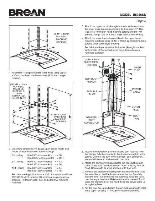
model B5936SS<br />
Page <br />
(8) M4 x 10mm<br />
PAN HEAD<br />
MACHINE<br />
SCREWS<br />
3. Attach the upper set of (4) angle brackets to the outside of<br />
the lower angle brackets according to dimension “H”. Use<br />
(16) M4 x 10mm pan head machine screws and (16) M4<br />
serrated flange nuts (4 at each angle bracket connection).<br />
4. Attach the angle bracket assemblies to the upper hood<br />
mounting locations using (8) M4 x 10mm pan head machine<br />
screws (2 for each angle bracket).<br />
For 10-ft. ceilings: Attach a third set of (4) angle brackets<br />
to the inside of the second set of angle brackets using<br />
hardware supplied.<br />
1. Assemble (4) angle brackets to the hood using (8) M4<br />
x 10mm pan head machine screws (2 for each angle<br />
bracket).<br />
(16) M4 x 10mm<br />
PAN HEAD<br />
MACHINE<br />
SCREWS &<br />
(16) M4<br />
SERRATED<br />
FLANGE NUTS<br />
(4) M4 x 8mm<br />
SHEET METAL<br />
SCREWS<br />
non-duct<br />
plenum<br />
flexible<br />
duct<br />
FRONT<br />
inner<br />
flue<br />
power<br />
cable<br />
3”<br />
(8) M4 x 10mm<br />
PAN HEAD<br />
MACHINE<br />
SCREWS<br />
H<br />
damper /<br />
duct<br />
connector<br />
outer<br />
flue<br />
duct<br />
tape<br />
2. Determine dimension “H” based upon ceiling height and<br />
height of hood installation above cooktop:<br />
8-ft. ceiling <strong>Hood</strong> 30” above cooktop H = 30”<br />
<strong>Hood</strong> 30½” above cooktop H = 29½”<br />
9-ft. ceiling <strong>Hood</strong> 30” above cooktop H = 42”<br />
<strong>Hood</strong> 36” above cooktop H = 36”<br />
10-ft. ceiling <strong>Hood</strong> 30” above cooktop H = 54”<br />
<strong>Hood</strong> 36” above cooktop H = 48”<br />
For 10-ft. ceilings: Purchase a 10-ft. flue extension (Model<br />
FXN59SS) which includes (4) additional angle mounting<br />
brackets, (1) longer upper flue, and additional mounting<br />
hardware.<br />
5. Measure the length of 6” round flexible duct required from<br />
the damper / duct connector to the ductwork rough-in in the<br />
ceiling. Connect the duct to the damper / duct connector,<br />
secure with tie wrap and seal with duct tape.<br />
6. Attach the aluminum flexible duct to the non-duct plenum<br />
collar. Make sure non-duct plenum “front” is facing front of<br />
hood. Secure with tie wrap and seal with duct tape.<br />
7. Remove the protective coating from the inner the flue. Turn<br />
the inner flue so that the louvers are at the top. Carefully<br />
slide the inner flue down into the outer flue. Slide the flues<br />
over the angle brackets. Make sure the side marked “front”<br />
faces the control side of the hood. Feed the power cable up<br />
through the flues.<br />
8. Pull the inner flue up and attach the non-duct plenum with collar<br />
to the upper flue using (4) M4 x 8mm sheet metal screws.