PAX-30-120+ manual.qxd - Alecto
PAX-30-120+ manual.qxd - Alecto
PAX-30-120+ manual.qxd - Alecto
You also want an ePaper? Increase the reach of your titles
YUMPU automatically turns print PDFs into web optimized ePapers that Google loves.
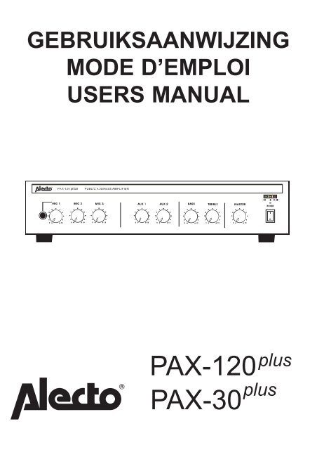
GEBRUIKSAANWIJZING<br />
MODE D’EMPLOI<br />
USERS MANUAL<br />
<strong>PAX</strong>-120 plus<br />
<strong>PAX</strong>-<strong>30</strong> plus
NL: Gebruiksaanwijzing . . . . . . 3<br />
Garantiebewijs . . . . . . . . . . 25<br />
FR: Mode d’emploi . . . . . . . . . . 11<br />
Bon de garantie . . . . . . . . . 26<br />
GB:users manaul . . . . . . . . . . . 17<br />
Guarantee card . . . . . . . . . 27<br />
Technical Specifications . . . . . . 24<br />
2
FUNCTIES<br />
NL<br />
1. Microfoon jack input<br />
2. Microfoon 1 volumeregelaar<br />
3. Microfoon 2 volumeregelaar<br />
4. Microfoon 3 volumeregelaar<br />
5. Aux 1 volumeregelaar<br />
6. Aux 2 volumeregelaar<br />
7. Lage-tonenregelaar<br />
8. Hoge-tonenregelaar<br />
9. Master-volumeregelaar<br />
10. Netschakelaar<br />
11. LED-VU-meter<br />
12. Spannings instelschakelaar.<br />
13. Netingang (2<strong>30</strong>V / 115V)<br />
14. Zekering <strong>PAX</strong>-<strong>30</strong> (T 1A/250V)<br />
<strong>PAX</strong>-120 (T 2.5A/250V)<br />
15. Aansluitstrip voor 24V en luidsprekers<br />
16. Line/microfoon instelschakelaar<br />
17. Mic.3 XLR-ingang<br />
18. Mic.3 Jack-ingang<br />
19. Mic.2 XLR-ingang<br />
20. Mic.2 Jack-ingang<br />
3<br />
21. Mic 1 XLR-ingang<br />
22. Mic 1 DIN-ingang / CHIME / MUTE<br />
connector<br />
23. Aan/uit-schakelaar CHIME<br />
24. Aansluiting effectapparaart<br />
25. CINCH-uitgang voor tape recorder<br />
26. CINCH AUX 2 ingang<br />
27. CINCH AUX 1 ingang<br />
28. Telefoonoproep ingang<br />
29. Volumeregelaar voor telefoon ingang
INSTALLATIE<br />
ATTENTIE<br />
Zorg eroor dat de ventilatieopeningen aan de boven- en onderzijde van de versterker<br />
vrijblijven om een gelijkmatige warmteafvloeiing te garanderen.<br />
Pas nadat alle in- en uitgangen zijn aangesloten, mag de voeding worden aangesloten.<br />
Zet veiligheidshalve de POWER schakelaar van de versterker op uit (0) en draai alle<br />
regelaars op minimaal (0).<br />
INGANGEN<br />
MICROFOON:<br />
De microfooningangen zijn voorzien van een XLR-, en een jack-ingang en zijn gebalanceerd<br />
uitgevoerd. Microfoon 1 is tevens voorzien van een DIN ingang.<br />
XLR aansluiting<br />
Pin 1 = afscherming (GND)<br />
Pin 2 = signaal +<br />
Pin 3 = signaal -<br />
Jack aansluitingPin 1 = afscherming (GND)<br />
(achterzijde)* Pin 2 = signaal -<br />
Pin 3 = signaal +<br />
DIN aansluiting Pin 1 = Signaal +<br />
Pin 2 = afscherming (GND)<br />
Pin 3 = Signaal -<br />
Pin 4 = CHIME<br />
Pin 5 = GND<br />
*: de jackaansluiting aan de voorzijde is een standaard 6.3mm mono uitvoering<br />
Fantoomvoeding:<br />
Via een jumpertje kan de fantoomvoeding,<br />
welke voor bepaalde condensatormicrofoons<br />
nodig zijn, worden geactiveerd. Dit jumpertje<br />
zit op de printplaat, binnen in de <strong>PAX</strong>-<strong>30</strong>/120.<br />
BIJ HET VERWIJDEREN VAN DE KAP VAN<br />
DE VERSTERKER, ALTIJD DE STEKKER<br />
UIT HET STOPCONTACT NEMEN.<br />
Plaats eerst de kap terug op de versterker alvorens<br />
de voeding weer in te schakelen.<br />
4
MUTE:<br />
Op microfoon 1 is een MUTE functie actief. Zodra en zolang er door microfoon 1<br />
gesproken wordt, worden alle overige signalen onderdrukt behalve de TEL/EMER aansluiting.<br />
CHIME:<br />
Zodra PIN-4 en PIN-5 met elkaar doorverbonden worden, klinkt er een DING DONG<br />
signaal en worden de muzieksignalen onderdrukt. Deze doorverbinding kan middels<br />
een eenvoudige drukknop gerealiseerd worden of kan worden ingebouwd in een<br />
(tafel)microfoon).<br />
MIC-3 / LINE:<br />
MIC 3 kan ook dienen als line-kanaal. Hiervoor dient schakelaar LINE/MIC in de positie<br />
‘line’ te worden gezet.<br />
AUX:<br />
De <strong>PAX</strong>-<strong>30</strong>/120 heeft twee ingangen voor muziekbronnen: AUX-1 en AUX-2. Deze stereo<br />
ingangen zijn intern mono geschakeld. Sluit hier een apparaat op aan welke een<br />
uitgangssignaal op line-niveau levert (zoals tape, tuner, CD, DVD of video speler).<br />
Indien de schakelaar LINE/MIC in de positie ‘LINE’ is gezet, is deze ingang ook<br />
geschikt voor muziekbronnen op line-niveau.<br />
TEL/EMER:<br />
Deze ingang kan verbonden worden met een van de telefoonaansluitingen van een<br />
telefooncentrale voor omroep via een telefoontoestel. Let op dat alleen telefooncentrales<br />
met een ruimtebeluister- of babyfoon-functie aangesloten kunnen worden. Bij de<br />
telefooncentrale zet u dan de aansluiting waarop de versterker is aangesloten in de<br />
modus ‘babyfoon’. Raadpleeg bij twijfel de gebruiksaanwijzing van de telefoon centrale<br />
of neem contact op met de leverancier ervan.<br />
5
POWER IN:<br />
Op deze ingang kan een effect apparaat worden aangesloten, zie item pre-out bij het<br />
hoofdstuk UITGANGEN voor verdere uitleg.<br />
UITGANGEN<br />
LAAGOHMIG:<br />
Gebruik de COM - 8 ohm uitgang indien de afstand tot aan de luidsprekers korter is<br />
dan 50 à 75 meter. De aangesloten luidsprekers moeten laagohmig (8-16 ohm) zijn.<br />
Bij het gebruik van laag ohmige luidsprekers, moet het totaal vermogen van alle<br />
luidsprekers gelijk of meer zijn dan het versterker vermogen (anders zal bij vol<br />
versterkerkermogen een of meer luidsprekers worden beschadigd) en moet ook de<br />
eind impedantie tussen 8 en 16 ohm uitkomen.<br />
Bij het in serie schakelen van de<br />
luidsprekers moeten de individuele<br />
impedanties bij elkaar worden<br />
opgeteld.<br />
Bij het parallel schakelen van<br />
gelijkwaardige luidsprekers moet<br />
de impedantie van één enkele<br />
luidspreker gedeeld worden door<br />
het aantal luidsprekers.<br />
Maak eventueel gebruik van een<br />
combinatie van serie en parallel<br />
schakelen, om de vereiste impedantie<br />
te bereiken.<br />
LIJNUITGANG:<br />
Gebruik de COM - 25V, COM - 70V of COM - 100V bij luidsprekerafstanden van meer<br />
dan 50 à 75 meter. Gebruik alleen luidsprekers met een lijntransformator.<br />
Bij aansluiting op de 100 volt uitgang moet het bij elkaar opgeteld vermogen van alle<br />
aangesloten luidsprekers (lees luidsprekertrafo's) gelijk of minder bedragen dan het<br />
RMS vermogen (<strong>PAX</strong>-<strong>30</strong> = <strong>30</strong>Watt/ <strong>PAX</strong>-120 = 120 Watt) van de versterker; worden er<br />
meer luidsprekers aangesloten dan de versterker aan stroom kan leveren dan kan de<br />
versterker defect raken (let op: dit is ongeacht de stand van de volumeregelaars).<br />
6
Komt, bij totaaltelling, het luidsprekervermogen toch boven het versterkervermogen,<br />
gebruik dan de 70-volt uitgang; het is nu toegestaan om tot een luidsprekervermogen<br />
te gaan die 2 x zo groot is als het versterkervermogen, of gebruik de 25 volt uitgang;<br />
het is nu toegestaan om tot een luidsprekervermogen te gaan die 4 x zo groot is als<br />
het versterkervermogen. De maximale haalbare geluidsdruk per luidspreker is nu wel<br />
lager.<br />
Alle luidsprekers moeten parallel aangesloten<br />
worden; bij het 100-volt systeem is serieschakeling<br />
niet toegestaan.<br />
In de regel zijn de luidsprekerlijntrafo's voorzien<br />
van diverse vermogensaftakkingen waardoor een<br />
grote flexibiliteit verkregen wordt.<br />
Gebruik de laagvermogen aftakking waar minder<br />
volume vereist is en gebruik de hoogvermogen<br />
aftakking waar meer volume gewenst is.<br />
Het is toegestaan om individuele luidsprekers te<br />
voorzien van een aan/uit schakelaar of om de diverse<br />
aftakkingen van de lijntransformator te voorzien van<br />
een draaischakelaar waardoor een vorm van volumeregeling<br />
verkregen wordt.<br />
Voor de telling van het max. aangesloten vermogen dient in het geval van een draaischakelaar<br />
het hoogste vermogen worden genomen.<br />
BIJ GEBRUIK VAN HET 25-, 70- OF 100-VOLT LUIDSPREKERSYSTEEM,<br />
DIENEN DEZELFDE RICHTLIJNEN IN ACHT GENOMEN TE WORDEN ALS DE<br />
RICHTLIJNEN DIE GELDEN VOOR HET LICHTNET. RAADPLEEG UW PLAATSE-<br />
LIJKE INSTALLATEUR OF ENERGIEBEDRIJF.<br />
TAPE OUT:<br />
Via de tape out ingang kan mbv. een cassettedeck, mini-disc of een ander opname<br />
apparaat het geluidsignaal worden opgenomen. Het telefoonsignaal wordt niet mee<br />
opgenomen.<br />
PRE-OUT:<br />
Pre-out is een uitgang waar het totale geluidsignaal, inclusief de telefooningang, op<br />
line-niveau aanwezig is. Vanaf de fabriek is deze uitgang door middel van een U-stekker<br />
doorverbonden met de ingang ‘Power-in’. Indien u deze doorverbinding verwijderd,<br />
kunt u een limiter of een effect-apparaat (equalizer, echo/nagalm e.d.) aansluiten.<br />
Ook is het mogelijk om met een speciale verdeelstekker het pre-out-signaal te splitsen<br />
voor aansluiting naar een extra versterker.<br />
7
VOEDING<br />
Plug het netsnoer in aansluiting 2<strong>30</strong>VAC aan de achterzijde, en steek de stekker in<br />
een randaarde wandcontactdoos, of sluit een 24V accu aan op de 24 VDC klemmen<br />
aan de achterzijde van de <strong>PAX</strong>-<strong>30</strong>/120 (Let hierbij goed op de polariteit).<br />
Waarschuwing:<br />
Bij gebruik van accuvoeding, zal het chassis van de versterker verbonden zijn met<br />
de - (min) van de voeding. Bij gebruik van het 2<strong>30</strong> Volt lichtnet als voeding, zal het<br />
chassis van de versterker verbonden zijn met de aarde van het lichtnet. De versterker<br />
alleen op een geaarde wandcontactdoos aansluiten.<br />
GEBRUIK<br />
ATTENTIE:<br />
Zet, alvorens u de versterker inschakelt, veiligheidshalve alle regelaars op minimaal.<br />
MUZIEK:<br />
Met de AUX-1/2 regelaars regelt u het volume van de muziekbronnen die<br />
aangesloten zijn op de ingangen AUX-1 en AUX-2. Ingang MIC-3 kan met schakelaar<br />
line-mic omgezet worden naar line zodat dit kanaal geschikt is voor linesignalen. Met<br />
regelaar MIC 3 kan nu het volume van de muziekbron geregeld worden welke is aangesloten<br />
op mic 3 ingang.<br />
MICROFOON:<br />
De regelaars MIC-1, MIC-2 en MIC-3 regelen het volume van de microfoons<br />
die aangesloten zijn op de respectievelijke ingangen (zie achterzijde versterker).<br />
MASTERVOLUME:<br />
Met de mastervolumeregelaar kan het totale geluidsbeeld in volume geregeld worden.<br />
Alleen de TEL/EMER-ingang heeft voorrang op deze regeling. Dit volume kan alleen<br />
met de TEL/EMER regelaar (29) aan de achterzijde geregeld worden.<br />
TOONREGELING:<br />
Gebruik de knop BASS om de lage tonen te versterken (rechtsom) of te<br />
verzwakken (linksom). Gebruik de knop TREBLE om de hoge tonen te versterken<br />
(rechtsom) of te verzwakken (linksom).<br />
TEL/EMER VOLUME<br />
Met de volume-instelknop (zie 29) aan de achterzijde kan het volume van het telefoonsignaal<br />
geregeld worden. Deze regeling gaat buiten de mastervolumeregeling om.<br />
8
MUTE:<br />
Zodra en zolang er gesproken wordt in de microfoon die aangesloten is op de MIC-1<br />
ingang, worden alle geluidssignalen, exclusief de signalen van de telefoonaansluiting<br />
(TEL/EMER), onderdrukt.<br />
CHIME:<br />
Via de pinnen 4 en 5 van de MIC1-DIN ingang aan de achterzijde, kan met behulp van<br />
een drukknop een DING DONG signaal worden geactiveerd. Deze externe drukknop<br />
kan ook in een tafelmicrofoon worden gemonteerd.<br />
WAARSCHUWING/ONDERHOUD<br />
- de versterker is voor gebruik binnenshuis, in een droge omgeving; gebruik de<br />
versterker nooit in een vochtige of natte omgeving.<br />
- laat geen voorwerpen door de ventilatieopeningen in de versterker vallen;<br />
gebeurt dit wel, schakel dan DIREKT de voeding uit (ook de toevoer) en breng de<br />
versterker ter controle naar uw leverancier.<br />
- zowel aan de onder- als aan de bovenzijde dient een ruimte van 1 tot 2 cm vrij te<br />
blijven zodat overtollige warmte onbelemmerd afgevoerd kan worden.<br />
- het chassis van de versterker is verbonden met de aarde van het netsnoer en met<br />
de - (min) van een DC voeding.<br />
- reinig de behuizing alleen met een licht vochtige doek; schakel eerst de versterker<br />
uit alvorens u deze reinigt.<br />
- schakel de versterker alleen in nadat alle volumeregelaars op MINIMUM (0)<br />
gedraaid zijn, dit voorkomt schrikeffect.<br />
- het langdurig bloot staan aan een hoog geluidsvolume kan het gehoor<br />
beschadigen.<br />
- zorg voor een zodanig volume dat andere geluidssignalen uit de omgeving<br />
onbelemmerd tot u en anderen kunnen doordringen.<br />
9
FR<br />
FONCTIONS<br />
1. Entrée microphone 1 (jack)<br />
2. Contrôle de volume microphone 1<br />
3. Contrôle de volume microphone 2<br />
4. Contrôle de volume microphone 2<br />
5. Contrôle de volume Aux 1<br />
6. Contrôle de volume Aux 2<br />
7. Contrôle le grave<br />
8. Contrôle l'aigu<br />
9. Contrôle de volume “Master”<br />
10. Interrupteur alimentation<br />
11. LED-VU<br />
12. Commutateur 115/2<strong>30</strong>V<br />
13. Entrée (2<strong>30</strong>V / 115V)<br />
14. Fusible <strong>PAX</strong>-<strong>30</strong> (T 1A/250V)<br />
<strong>PAX</strong>-120 (T 2.5A/250V)<br />
15. Prise 24V et haut-parleur<br />
16. Commutatuer Line/MIC3<br />
17. Entrée microphone 3 (XLR)<br />
18. Entrée microphone 3 (jack)<br />
19. Entrée microphone 2 (XLR)<br />
20. Entrée microphone 2 (jack)<br />
21. Entrée microphone 1 (XLR)<br />
22. Entrée microphone 1 (DIN)<br />
raccordement CHIME / MUTE<br />
23. Commutateur CHIME<br />
24. Jonction appareils déffects<br />
25. Sortie d’enregistrement<br />
26. Entrée AUX2 (cinch)<br />
27. Entrée AUX1 (cinch)<br />
28. Entrée signal téléphonique<br />
29. Contrôle de volume signal<br />
téléphonique<br />
10
L'INSTALLATION<br />
ATTENTION<br />
Faites attention à la ventilation; afin de garantir un écoulement de la chaleur, il est<br />
nécessaire de ne pas couvrir l'aération.<br />
Des que vous avez brancher toutes les sorties et les entrées, vous pouvez brancher<br />
l'alimentation. Mettez pour des raisons de securité l'interrupteur POWER à 0 et mettez<br />
toutes les régulateurs au minimum (0).<br />
ENTRÉES<br />
MICROPHONE:<br />
Les entrées microphones sont pourvu d'une XLR et une entrée jack qui sont équilibrée.<br />
Microphone 1 et pourvu d'une entrée DIN.<br />
Raccordement XLR<br />
Raccordement Jack<br />
contact 1 = blindé (GND)<br />
contact 2 = signal +<br />
contact 3 = signal -<br />
contact 1 = blindé (GND)<br />
contact 2 = signal -<br />
contact 3 = signal +<br />
Raccordement DIN contact 1 = signal +<br />
contact 2 = blindé (GND)<br />
contact 3 = signal -<br />
contact 4 = CHIME<br />
contact 5 = GND<br />
*: le raccordement sur le devant est standard 6,3 mm. mono.<br />
Alimentation Fantoom:<br />
Par la petite fiche (jumper) vous pouvez activer<br />
l'alimentation fantoom. Celle-ci est pour des<br />
microphones-condensateurs. Cette petite fiche<br />
se trouve sur le circuit électronique à l'interieur<br />
du <strong>PAX</strong>-<strong>30</strong>/120.<br />
SI VOUS ENLEVEZ LE KAPOT DU AMPLIFI-<br />
CATEUR, DEBRANCHEZ LA FICHE DE SEC-<br />
TEUR.<br />
Mettez nouveau le kapot sur l'amplificateur avant brancher la fiche de secteur.<br />
11
MUTE:<br />
Sur le microphone 1, la fonction MUTE est activé. Pendant une communication dans le<br />
microphone, touts les autres signaux sont coupé, sauf la raccordement TEL/EMER.<br />
CHIME:<br />
Des qu'on a fait le pont entre contact 4 et 5, vous attendez un signal DING DONG et<br />
touts les signaux sont coupé. On peut faire cette pontage des contact 4 et 5 par un<br />
interrupteur - encastré dans un microphone de table.<br />
MIC-3 / LINE:<br />
Vous pouvez utillisez MIC 3 comme canal-line. Il faut mettre l'interrupteur LINE/MIC en<br />
position LINE.<br />
AUX:<br />
Le <strong>PAX</strong>-<strong>30</strong>/120 a deux entrées pour des sources musicales : AUX1 et AUX2. Cettes<br />
entrées stereo sont à l'interieur brancher a la façon mono.Raccordez sur cette entrée<br />
un appareil en niveau-line (comme CD, DVD, VCR etc..).<br />
Si vous avez mis l'interrupteur LINE/MIC en position LINE, cette entrée est exigeant<br />
pour des sources musicale au niveau Line.<br />
TEL/EMER:<br />
Cette entrée peut être brancher à un raccordement téléphonique d'un centrale pour un<br />
appel par un téléphone. Faites attention que vous pouvez brancher uniquement des<br />
centraux avec la fonction monitoring ou la fonction babyphone. Vous devez mettre<br />
votre centrale au fonction babyphone. Consultez votre mode d'emploi de votre centrale<br />
téléphonique.<br />
POWER IN :<br />
Vous pouvez brancher sur cette entrée un appareil des effects, voir pre-out, chapitre<br />
SORTIES pour des explications supplementaires.<br />
12
LA SORTIE<br />
OHM BAS:<br />
En cas que la distance entre les haut-parleurs est moins que 50 à 75 mètres, il faut utiliser<br />
la sortie COM-8 Ohm. Les haut-parleurs doivent avoir la impedance entre le 4 et<br />
le 16 Ohm.<br />
Si vous utilisez des haut-parleurs<br />
en ohm bas, la puissance totale<br />
doit être pareille ou plus que la<br />
puissance de l'amplificateur<br />
(sinon, vous pouvez endommager<br />
un ou plusieurs haut-parleurs).<br />
L'impédance final doit être entre les 4 et les 16 ohm.<br />
Additionnez les impédances individuelles<br />
de chaque haut-parleur en cas d'une<br />
couplage en série.<br />
Divisez l'impédance d'un seul haut-parleur<br />
par le nombre d'haut-parleurs en cas d'une<br />
couplage en parallèle.<br />
Il est possible de combiner une couplage en série avec une couplage en parallèle afin<br />
d'atteindre l'impédance exigée.<br />
SORTIE LIGNES:<br />
Utilisez la sortie COM-25V, COM-70V ou la sortie COM-100V si la distance entres les<br />
haut-parleurs est plus que 50 à 75 mètres. Utilisez des haut-parleurs avec un transformateur<br />
de sortie lignes.<br />
La puissance totale de chaque haut-parleur<br />
raccordé doit être pareille ou moins que la<br />
puissance effective de l'amplificateur<br />
(cfr. les données techniques); si la puissance<br />
des haut-parleurs raccordés est plus grand<br />
que le courant livré par l'amplificateur,<br />
l'amplificateur grillera (indépendant de la<br />
position du bouton de contrôle du volume).<br />
Utilisez la sortie de 70 Volt si la puissance totale des haut-parleurs raccordés dépasse<br />
la puissance de l'amplificateur, maintenant, la puissance des haut-parleurs peut être la<br />
double de la puissance de l'amplificateur. Ou utillisez la sortie 25 Volt; il est permetter<br />
de raccorder des haut-parleur avec une puissance qui est 4 x la puissance de l'amplificateur.<br />
13
Branchez les haut-parleurs en parallèle; une couplage en série est interdite chez un<br />
système de 100 volt.<br />
Le transformateur d'un haut-parleur est pourvu de plusieurs<br />
branchements, utilisez le branchement de la capacité basse<br />
pour un volume petit et utilisez le branchement de la capacité<br />
plus fort si vous désirez plus de volume.<br />
Vous pouvez brancher un commutateur de mise en marche ou un bouton de<br />
contrôle du volume sur cheque haut-parleur.<br />
RESPECTEZ LES DIRECTIVES DU RESEAU DE 2<strong>30</strong> VOLT SI VOUS UTILISEZ UN<br />
SYSTEME D'HAUT-PARLEURS DE 70 OU 100 VOLT. CONSULTEZ L'INSTALLA-<br />
TEUR LOCAL OU LA COMPAGNIE DISTRIBUTEUR D'ENERGIE.<br />
TAPE OUT:<br />
Par l'entrée tape out, vous pouvez enregistrer des signaux de bruit avec un cassette,<br />
mini-disc ou autre appareils d'enrégistrage. Il est inpossible de enregistrer des signaux<br />
téléphoniques<br />
PRE-OUT:<br />
Pre-out est une sortie avec les signaux totales, incl. le signal téléphonique en niveau<br />
line. A l'usine, cette sortie est connecter par une fiche-U à l'entrée Power-In.<br />
Si vous enlevez cette connection, vous pouvez brancher des appareils d'effects ou un<br />
equalizer.<br />
Vous pouvez brancher aussi une fiche de partage pour diviser le signal pre-out vers un<br />
autre amplificateur.<br />
L'ALIMENTATION:<br />
Reliez, à votre choix, l'amplificateur au réseau secteur (fil d'alimentation fourni) ou à un<br />
courant continu de 24 volt. (il est nécessaire que l'alimentation de 24 volt livre 240watt<br />
(10 amp.) au minimum)<br />
Avertissement:<br />
En utilisant un accumulateur, le chassis de l'amplificateur sera relié avec le póle négatif<br />
de l'alimentation. En utilisant le réseau de 2<strong>30</strong> volt comme alimentation, le chassis de<br />
l'amplificateur sera relié avec le terre du réseau. Raccordez l'amplificateur à une prise,<br />
mise à la terre.<br />
14
L'UTILISATION<br />
ATTENTION:<br />
Mettez toutes les interrupteur à minimum avant de mettre l'amplificateur en marche.<br />
LA MUSIQUE:<br />
Ajustez re volume des sources musicales en utilisant les régulateurs AUX-1/2, raccordés<br />
sur les entrées AUX-1 et AUX-2. Vous pouvez changer entrée MIC-3 avec l'interrupteur<br />
line-mic à line pour utillisez cette entrée avec des signaux line. Avec le régulateur<br />
MIC 3, vous pouvez régler la volume de la source musicale qui est brancher à<br />
l'entrée MIC 3.<br />
MICROPHONE:<br />
Les régulaleurs MIC-1, MIC-2 et MIC-3 règlent le volume des microphones<br />
raccordés sur les entrées respectives (l'arrière de l'amplificateur).<br />
MASTERVOLUME:<br />
Avec le régulateur master, vous pouvez régler la volume totale. Uniquement l'entrée<br />
TEL/EMER a priorité à cette réglage. Vous pouvez régler uniquement cette volume à<br />
l'arriere (29).<br />
LE CONTRÔLE DE TONALITÉ:<br />
Utilisez le bouton BASS afin d'amplifier les sons graves (à droite) ou tournez ce bouton<br />
à gauche afin de diminuer les sons graves. Utilisez le bouton TREBLE afin d'amplifier<br />
les sons aigus (à droite) ou tournez ce bouton à gauche afin de diminuer les sons<br />
aigus.<br />
TEL/EMER VOLUME:<br />
Avec le bouton-volume (voir 29) à l'arrière, vous pouvez régler la volume du signal<br />
téléphonique. Cette réglage est hors la réglage master.<br />
AUTO MUTE:<br />
Dès que el tant que vous parlez au microphone, raccordé sur l'entrée MIC-1, tous les<br />
autres signaux, excl. les signaux de raccordement téléphonique (TEL/EMER), seront<br />
retenus.<br />
CHIME:<br />
Par les contacts 4 et 5 de l'entrée MIC1-DIN à l'arrière, vous pouvez activer un signal<br />
Ding Dong qui ce fait par un bouton extern. Ce bouton peut être monter à un microphone<br />
de table.<br />
15
AVERTISSEMENT / ENTRETIEN<br />
- N'uttillisez jamais l'amplificateur en aucun cas dans un endroit humide.<br />
- L'amplificateur ne peut pas être ouvrit que par un technicien qualifié; l'amplificateur<br />
ne contient pas des pièces de réserve.<br />
- Ne laissez pas tomber des objets dans votre amplificateur; débrayez-le dans ce cas<br />
et appelez un technicien qualifié.<br />
- Espacez les ventilations (1 à 2 cm.) de manière que la chaleur excédentaire peut<br />
être écoulée.<br />
- Le châssis de l'amplificateur est relié avec le terre du fil d'alimentation et avec le "-"<br />
d'une alimentation CD.<br />
- Nettoyez l'amplificateur uniquement avec un chiffon doux; nettoyez le panneau<br />
frontal avec un chiffon légèrement humide (débranchez l'amplificateur).<br />
- Branchez l'amplificateur après vous avez vérifié les régulateurs du volume (volume<br />
minimal).<br />
- L'exposition prolongée au volumes élevés peut dommager l'ouïe.<br />
- Réglez le volume sur une telle manière que vous pouvez toujours entendre les<br />
autres sons dans l'entourage.<br />
16
FUNCTIONS<br />
GB<br />
1. Mic 1 input (phone)<br />
2. Mic 1 volume control<br />
3. Mic 2 volume control<br />
4. Mic 3 volume control<br />
5. Aux 1 volume control<br />
6. Aux 2 volume control<br />
7. Master tone control (bass)<br />
8. Master tone control (treble)<br />
9. Master-volume control<br />
10. Power ON/OFF switch<br />
11. Output level indicator<br />
12. Mains voltage selector switch<br />
13. Mains input socket<br />
14. AC fuse holder <strong>PAX</strong>-<strong>30</strong> (T1A/250V)<br />
<strong>PAX</strong>-120 (T 2.5A/250V)<br />
15. DC power & output terminals<br />
16. Mic 3 Line/Mic selector switch<br />
17. Mic.3 XLR-input (balanced)<br />
18. Mic.3 Jack-input (phone/balanced)<br />
19. Mic.2 XLR-input (balanced)<br />
20. Mic.2 Jack-input (phone/balanced)<br />
21. Mic 1 XLR-input (balanced)<br />
22. Mic 1 DIN-input (balanced)<br />
CHIME / MUTE connector<br />
23. CHIME ON/OFF switch<br />
24. Pre-out / Power-IN (RCA phono)<br />
25. Tape output (RCA phono)<br />
26. AUX 2 input (2x RCA phono)<br />
27. AUX 1 input (2x RCA phono)<br />
28. TEL/EMER input terminals<br />
29. TEL/EMER input level control<br />
17
INSTALLATION<br />
ATTENTION<br />
Make sure the ventilation openings at the top and bottom of the amplifier remain clear<br />
to guarantee a continuous convection.<br />
During installation, set the POWER switch of the amplifier to OFF (0) and set the MIC-<br />
1, 2 & 3 controls and the AUX-1 & 2 controls to minimum (0); do not connect the power<br />
supply yet.<br />
INPUT<br />
MICROPHONE:<br />
MIC1 input is either a standard 1/4" mono jack on front panel or XLR and DIN on the<br />
rear panel (with selectable phantom power).<br />
XLR (balanced operation)<br />
Pin 1 = ground (GND)<br />
Pin 2 = signal live<br />
Pin 3 = signal return<br />
1/4” stereo Jack (balanced operation (backside only)*<br />
Pin 1 = ground (GND)<br />
Pin 2 = signal live<br />
Pin 3 = signal return<br />
DIN (balanced operation)<br />
Pin 1 = Signal live<br />
Pin 2 = ground (GND)<br />
Pin 3 = Signaal -<br />
Pin 4 = CHIME<br />
Pin 5 = GND<br />
*: the frontside 1/4” jack is a standard mono version<br />
MIC1 input has VOX priority which will override MIC2 / MIC3 and AUX1 / AUX2 input<br />
signals but NOT the TEL/EMER input.<br />
MIC1-3 input are XLR, DIN and phone jack with selectable phantom power located on<br />
the rear panel and wired as above. The phantom power is factory set to off and can be<br />
enabled as follow:<br />
18
1. Remove power lead trom the AC wall socket.<br />
2. Remove top cover.<br />
3. Locate the jumper<br />
4. connect jumper to the centre pin and ON position<br />
to enable the phantom power<br />
ALWAYS DISCONNECT THE AMPLIFIER FROM<br />
THE MAINS WHEN REMOVING THE COVER.<br />
CHIME:<br />
Switching on the <strong>manual</strong> chime on/off switch on the rear panel and short the pin4, pin5<br />
of the DIN Socket will activate the chime function ("Ding-Dong" attention signal preceding<br />
a call).<br />
AUX:<br />
The equipment provides two auxiliary inputs which may be used for connecting other<br />
signal sources such as a Radio Tuner, CD or Cassette player. The level Control operates<br />
on each of the input sources. Turn the control clockwise to increase the volume or<br />
anticlockwise to reduce the volume.<br />
The Aux input sockets are standard RCA phono, two sockets are supplied and these<br />
are linked together internally, this allows stereo signal sources to be used without the<br />
need to obtain a special lead, however you may wish to check with the manufacturer of<br />
the signal source to ensure that no damage will result if the left and right output channels<br />
are put in parallel.<br />
In case the backside switch LINE/MIC is set to ‘LINE’ this input can be used for music<br />
as well.<br />
TEL/EMER:<br />
This input is for emergency announcements/signals and is not effected by the master<br />
volume control. Input level can be set by level control on the rear. The TEL input has<br />
the highest priority and will override all other inputs.<br />
Be aware that the telephone exchange must have a ‘babyphone’ or ‘room listening’<br />
functionality.<br />
POWER IN AND PRE OUT:<br />
Connects the mixer/preamplifier stage to the power amplifier stage. The connecting link<br />
must be plugged in for normal operation as a mixer/amplifier. If a compressor/limiter,<br />
equalizer, or other external signal processor is used in the sound system, connect the<br />
"PRE OUT to the input of the external processor and the output of the processor to"<br />
POWER IN" In the signal chain, "PRE OUT' is after the tone controls and the master<br />
volume control.<br />
19
OUTPUTS<br />
LOW IMPEDANCE:<br />
Use the COM-8 Ohm output in case the distance to the loudspeakers is shorter than<br />
50 t0 75 metres.<br />
When using low impedance loudspeakers, the total power of the loudspeakers<br />
should be equal or larger than the amplifier output. Otherwise one or more<br />
loudspeakers will be damaged when<br />
the output is at its maximum. Make<br />
sure the total impedance remains<br />
in between 4 and 16 ohm:<br />
When connected in series, the<br />
impedances of each of the speakers<br />
can be added.<br />
When (equal) loudspeakers are<br />
connected in parallel, the impedance<br />
of a single loudspeaker must be<br />
devided by the number of speakers.<br />
Eventually, use a combination of series<br />
and parallel connection to obtain the<br />
required impedance.<br />
LINE OUTPUT:<br />
Use the COM-25V, COM-70V or COM-100 V output terminals for loudspeaker-distances<br />
of more than 50 to 75 metres. Use only speakers with a line transformer.<br />
In case of connection to the 100 volt output,<br />
the power of all loudspeaker (-transformers)<br />
connected should be equal or less than the<br />
effective RMS output power of the amplifier<br />
(<strong>PAX</strong>-<strong>30</strong> = <strong>30</strong> Watt / <strong>PAX</strong>-120 = 120Watt).<br />
Should more loudspeakers be connected than<br />
the amplifier can supply, the amplifier will burn<br />
out no matter what the settings of the volume<br />
controls are.<br />
All loudspeakers should be connected in parallel; with the 100 volts system, series<br />
connection is not allowed.<br />
20
In case the total loudspeakerpower exceeds the amplifier's power, use the 70 volt output;<br />
it is now allowed to connect loudspeakers up to twice the amplifier power.<br />
When the 25V output is used, it is allowed to connect loudspeakers up to 4 times the<br />
amplifier power<br />
As a rule of thumb, loudspeaker transformers are provided<br />
with several power terminals obtaining a larger flexability;<br />
use the low power terminal where less volume is required<br />
and use the high power terminal where more volume is<br />
requlred.<br />
It is allowed to provide individual loudspeakers with an on/off switch or with a rotary<br />
switch (with connections to several terminals) to obtain a kind of volume control.<br />
WHEN USING THE 25, 70 OR 100 VOLTS LOUDSPEAKER SYSTEM, THE SAME<br />
RULES SHOULD BE APPllED AS ARE VALID FOR THE 2<strong>30</strong> VOLTS MAINS SUP-<br />
PLY. COUNCEL YOUR ENERGY COMPANY.<br />
TAPE OUT:<br />
These standard RCA phono sockets provide a mixed output suitable for connection to<br />
a tape or Cassette recorder.<br />
POWER SUPPLY:<br />
Connect the amplifier either to the mains 2<strong>30</strong> VAC (power cord included) or to a 24V /<br />
10A DC power source.<br />
WARNINGS:<br />
When using a battery supply, the cabinet of the amplifier will be connected to the “-”<br />
(minus) of the supply. When using a 2<strong>30</strong> Vac mains supply, the cabinet of the amplifier<br />
will be connected to the ground of the mains. Connect the amplifier to a grounded outlet<br />
only.<br />
21
USAGE<br />
ATTENTION:<br />
Prior to switch-on the amplifier, set the MIC-1, 2 & 3 controls and the AUX-1 & 2 controls<br />
to minimum (0).<br />
MUSIC:<br />
With the AUX-1/2 controls you control the volume of the music sources connected to<br />
the AUX-1/2 inputs. Input MIC-3 can be switched into a music input (position ‘LINE’).<br />
Use control MIC-3 to control the volume,<br />
Microphone:<br />
The MIC-1, MIC-2 and MIC-3 controls control the volume of the microphones connected<br />
to the equal named inputs (see rear of amplifier).<br />
MASTERVOLUME:<br />
Use the MASTER control to adjust the master volume except the volume from the<br />
TEL/EMER input.<br />
TONE CONTROL:<br />
Use the BASS control to amplify (clockwise) or weaken (anti-clockwise) the low frequency<br />
signals. Use the TREBLE control to amplify (clockwise) or weaken (anti-clockwise)<br />
the high frequency signals.<br />
TEL/EMER VOLUME:<br />
Use the control (29) on the rear to control the volume of the telephone / emergency<br />
signal. The MASTER control does not affect this volume.<br />
AUTO MUTE:<br />
As soon and as long there is speach present in the microphone connected to the MIC-<br />
1 input, all other signals, excluding the TEL/EMER input, are being supressed.<br />
CHIME:<br />
When connecting a pushbutton between PIN-4 and PIN-5 of the rear-side DIN socket,<br />
you can generate a DING DONG signal. This pushbutton can be built-in into a<br />
(table)microphone.<br />
22
WARNINGS/MAINTENANCE<br />
- never use the amplifier in moist or wet surroundings;<br />
- the amplifier may only be opened and repaired by authorised personnel; the<br />
amplifier does not contain spare parts;<br />
- do not (let) drop any objects through the ventilation holes; if this happens,<br />
immediately switch off the amplifier and cut the power supply. Bring your amplifier to<br />
your dealer;<br />
- make sure the ventilatlon openings at the top and bottom of the amplifier have a<br />
clearance of at least 1 to 2 cm to guarantee a continuous convection;<br />
- the cabinet of the amplifier is connected with ground of the mains and with the “-”<br />
(minus) of the DC supply;<br />
- clean the cabinet with a light moist cloth only; switch off the amplifier before you<br />
start cleaning;<br />
- switch on the amplifier only after setting all controls to MINIMUM (0), this prevents<br />
plops;<br />
- when exposed to a high volume for a long period of time, the hearing might be<br />
damaged;<br />
- set the volume in such a way that other sounds from the surroundings still reach you<br />
and others.<br />
23
SPECIFICATIONS<br />
Supply:<br />
AC115V / 2<strong>30</strong>V, 50 / 60Hz±10% switchable<br />
Battery Voltage:<br />
DC 24V (MAX 10 % deviation)<br />
Outputs:<br />
Speaker outputs: 8 Ohm, 25V, 70V, 100V<br />
<strong>PAX</strong>-<strong>30</strong>: Rated <strong>30</strong>W max. 45W<br />
<strong>PAX</strong>-120: Rated 120W max. 180W<br />
Tape out: 350mV, 4,7KOhm<br />
Inputs:<br />
Mic1~Mic3: 1mV, 250Ohm balanced with phantom<br />
power selectabel.<br />
Aux1: 200mV, 47KOhm, unbalanced.<br />
Aux2: 500mV, 47KOhm, unbalanced.<br />
Line (Mic3): 200mV, 47KOhm, balanced.<br />
TEL: 0.1~1V, 600Ohm, adjustable, balanced.<br />
Power in: 1V, 47KOhm, unbalanced<br />
Frequency response: Mic1~Mic3: 60Hz ~15KHz ±3dB<br />
Aux1~Aux2: 60Hz~15KHz ±3dB<br />
TEL : 100Hz ~ 15KHz ±3dB<br />
Total harmonic distortion: Less than 1% at 1KHz, rated power<br />
Signal to noise ratio: All volume controls C.C.W.:75dB below rated power<br />
Mic1 ~ Mic3: 60dB below rated power<br />
Aux1 ~ Aux2: 70dB below rated power<br />
TEL: 70dB below rated power<br />
Tone controls:<br />
Bass: ± 10dB at 100Hz<br />
Treble ± 10dB at 10KHz<br />
Controls:<br />
Mic1 ~ MIc3 volume control<br />
Aux1 ~ Aux2 volume control<br />
Master volume control<br />
Tone controls (Bass, Treble)<br />
TEL input level control<br />
Mic3(Line-Mic) selector switch<br />
Chime on/off switch<br />
AC 115V/2<strong>30</strong>V voltage selector switch<br />
Indicators:<br />
Power indicator (LED), output level indicators (3 LED)<br />
AC power consumption: <strong>PAX</strong>-<strong>30</strong> = 90 Watts <strong>PAX</strong>-120 = 360 watts<br />
DC power consumption: <strong>PAX</strong>-<strong>30</strong> = 2 A <strong>PAX</strong>-120 = 8A<br />
Priority (VOX):<br />
Priority level (Using for mic1, the 5 pole DIN<br />
connector, phone jack or XLR connector). TEL/EMER<br />
(3), Mic1 (2), Mic2 (1), Mic3 (1), and Aux/CD (1).<br />
Dimentions ( H x W x D ): 88 x 4<strong>30</strong> x 260 mm<br />
Weight: <strong>PAX</strong>-<strong>30</strong> = Approx 6.5Kg <strong>PAX</strong>-120 = Approx 9.5Kg<br />
Color:<br />
Black<br />
24
GARANTIEBEWIJS<br />
Naam:<br />
Adres:<br />
postcode:<br />
Plaats:<br />
Telefoon:<br />
serienummer:<br />
Bewaar hier<br />
uw kassa- of koopbon<br />
Op de <strong>Alecto</strong> <strong>PAX</strong>-<strong>30</strong>/120plus heeft u een garantie van 12 MAANDEN na aankoopdatum.<br />
Wij garanderen gedurende die periode de kosteloze herstelling van defecten<br />
ontstaan door materiaal- en constructiefouten. Een en ander ter uiteindelijke beoordeling<br />
van de importeur.<br />
HOE TE HANDELEN:<br />
Bemerkt u een defect, raadpleeg dan eerst deze gebruiksaanwijzing. Geeft deze<br />
hieromtrent geen uitsluitsel, raadpleeg dan de leverancier van deze portofoon<br />
Bij een defect kunt u de versterker, voorzien van een duidelijke klachtomschrijving en<br />
een gedateerde aankoopbon bij uw leverancier inleveren. Deze zal voor spoedige<br />
reparatie, resp. verzending naar de importeur zorgdragen.<br />
DE GARANTIE VERVALT:<br />
Bij ondeskundig gebruik, foutieve aansluiting, gebruik van niet originele onderdelen of<br />
toebehoren, verwaarlozing en bij defecten ontstaan door vocht, vuur, overstroming,<br />
blikseminslag en natuurrampen. Bij onbevoegde wijzigingen en/of reparaties door derden.<br />
Bij onjuist transport van het apparaat zonder geschikte verpakking en indien het<br />
apparaat niet vergezeld is van dit garantiebewijs en de aankoopbon.<br />
Iedere verdere aansprakelijkheid, met name voor eventuele gevolgschade, is uitgesloten.<br />
25
BON DE GARANTIE<br />
Nom<br />
Adresse<br />
Code postal<br />
Domicilie<br />
Téléphone<br />
Attachez ici votre bon de caisse ou d'achat<br />
Le <strong>Alecto</strong> <strong>PAX</strong>-<strong>30</strong>/120plus vous donne un garantie de 12 mois après date d'achat.<br />
Nous vous assurons pendant cette période une réparation gratuite des défauts causés<br />
par des défauts de construction ou de matériaux. Cela au jugement de l'importateur.<br />
COMMENT AGIR<br />
Si vous constatez un défaut, il faut d'abord consulter le mode d'emploi. Si cela ne vous<br />
sert à rien, il faut consulter votre fournisseur avec une description nette de votre réclamation.<br />
Celui-ci prendra l'appareil avec ce bon de garantie et le bon d'achtat daté et assurera<br />
une réparation rapide ou l'envoi à l'importateur.<br />
LA GARANTIE ECHOIT<br />
· En cas d'utilisation incompétente, d'un raccordement fautif, d'une utilisation des<br />
pièces détachées ou des accessoires pas originaux et en cas d'une négligence ou<br />
des défauts causés par incendie, inondation, foudre et catastrophes naturelles.<br />
· En cas de modifications illégales ou/et réparations par tiers.<br />
· En cas de transport fautif de l'appareil sans emballage approprié ou en cas où<br />
l'appareil n'est pas accompagné de ce bon de garantie et le bon d'achat.<br />
Tout autre responsabilité notamment aux conséquences éventuelles est excluse.<br />
26
GUARANTEE CARD<br />
CUSTOMER:<br />
Name:<br />
Address:<br />
Zip-code:<br />
City:<br />
Telephone:<br />
attach here<br />
your purchase<br />
ticket<br />
You have a guarantee of 12 MONTHS after the date of purchase of this<br />
<strong>PAX</strong>-<strong>30</strong>/120plus. We guarantee during this period the free repair of defects caused by<br />
material- and construction faults. This at the importers discretion.<br />
HOW TO ACT:<br />
If you notice a defect, consult the <strong>manual</strong> first. If this <strong>manual</strong> gives you no definite<br />
answer, consult your dealer with a clear description of your complaint. He will collect<br />
the device together with this guarantee card and the dated purchase ticket and he will<br />
take care of a prompt repair, respectively free sending to the importer.<br />
THE GUARANTEE EXPIRES:<br />
When used inexpert, faulty connections, use of unoriginal parts or accessories, negligence<br />
and defects caused by fire, flood, stroke of lightning and natural disasters. With<br />
unqualified modifications or repairs by third persons. With incorrect transport without a<br />
suitable packing. If the device is not handed in with the correct filled in guarantee card<br />
and the purchase ticket.<br />
All further responsibilities, in particular subsequent damages, are excluded.<br />
27


