MANUAL GRUPO HIDRÃULICO SUELO RADIANTE ... - Orkli
MANUAL GRUPO HIDRÃULICO SUELO RADIANTE ... - Orkli
MANUAL GRUPO HIDRÃULICO SUELO RADIANTE ... - Orkli

Create successful ePaper yourself
Turn your PDF publications into a flip-book with our unique Google optimized e-Paper software.
5.<br />
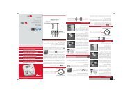
INSTALLATION AND START-UP<br />
6<br />
129<br />
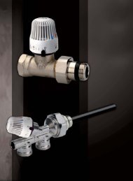
• Connecting the pipes<br />
We recommend making the connections to the hydraulic unit with the corresponding<br />
connectors before fixing the unit in place, to prevent damage to the EPP casing.<br />
• Wall mounting the hydraulic unit<br />
1. Drill holes in the wall for the rawl plugs at the distances shown.<br />
2. Place the fixing plate in the position shown and place the screws in the holes.<br />
Note: make sure the visible elements coincide with the holes in the hydraulic unit cover.<br />
• Filling the installation<br />
1. Turn the manual/motorised mixing valve to an intermediate position.<br />
2. Check the shut-off valves are open.<br />
3. Fill the circuit.<br />
4. Start up the pump, set to minimum pressure, and vary the operating setting to help drain the circuit (for the YONOS PARA pump,<br />
use the drain function). After draining the installation, leave the pump in operating position.<br />
• Electrical connections<br />
Pump:<br />
Mixer motor:<br />
Room temperature: . .. . .. . .. . .. . .. . .. . .. . .. . .. . .. . .. . max. +55 ºC<br />
.. . .. . .. . .. . .. . .. . .. . .. . .. . .. . .. . .. . .. . .. . .. . .. . .. . .. . .. min. -5 ºC<br />
Power supply:. .. . .. . .. . .. . .. . .. . .. . .. . .. . .. 230 ± 10% VCA.50 Hz<br />
Electricity consumption: . .. . .. . .. . .. . .. . .. . .. . .. . .. . .. . .. . .. 5 VA<br />
Protection type: . .. . .. . .. . .. . .. . .. . .. . .. . .. . .. . .. . .. . .. . .. . .. .IP41<br />
Protection class: . .. . .. . .. . .. . .. . .. . .. . .. . .. . .. . .. . .. . .. . .. . .. . .. . II<br />
Torque: . .. . .. . .. . .. . .. . .. . .. . .. . .. . .. . .. . .. . .. . .. . .. . .. . .. . .. 6Nm<br />
Nominal power of auxiliary switch: .. . .. . .. . .. . .. 6(3) A 250 V CA<br />
Weight: . .. . .. . .. . .. . .. . .. . .. . .. . .. . .. . .. . .. . .. . .. . .. . .. . .. . .0,4 kg<br />
M<br />
CCW<br />
bk<br />
CW<br />
bn<br />
N<br />
bu<br />
Phase (black): rotation direction<br />
Phase (brown): rotation direction<br />
Neutral (blue)<br />
Phase: brown<br />
Neutral: blue<br />
Earth: yellow-green<br />
C<br />
wh<br />
NO<br />
rd<br />
Common (white)<br />
Normally open (red)<br />
Normally closed<br />
NC<br />
og<br />
• High efficiency pump operation<br />
Led colour<br />
Continuous green<br />
Meaning Diagnostic Cause Remedy<br />
Quick green<br />
blinks<br />
Normal running<br />
Air venting routine running<br />
air<br />
Pump run as expected or is<br />
faced to a phenomenon that<br />
shortly affects its running<br />
Pump runs during 10 min in air<br />
venting function. Afterwards the<br />
installer has to adjust the targeted<br />
performance<br />
Normal running<br />
Δp-v<br />
Venting<br />
routine<br />
air<br />
Δp-c<br />
Red/green<br />
blinking<br />
Abnormal situation (pump<br />
functional but stopped)<br />
Pump will restart by itself after the<br />
abnormal situation disappeared<br />
1) Undervoltage or overvoltage:<br />
U253V<br />
1) Check voltage supply:<br />
195V< U