DEWALT Industrial Tool Co., 701 East Joppa Road, Baltimore, MD ...
DEWALT Industrial Tool Co., 701 East Joppa Road, Baltimore, MD ...
DEWALT Industrial Tool Co., 701 East Joppa Road, Baltimore, MD ...

Create successful ePaper yourself
Turn your PDF publications into a flip-book with our unique Google optimized e-Paper software.
English<br />
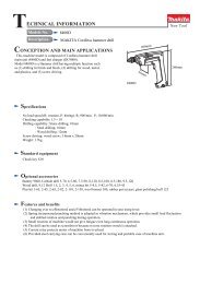
MATERIAL REMOVAL SCALE<br />
Your planer is equipped with a material removal scale,<br />
which indicates the amount of wood being removed in a<br />
planing operation. (Fig. 11 ) Ensure the workpiece is under<br />
the material removal gauge label on the front of the tool. The<br />
material removal gauge readout is to the right of this label.<br />
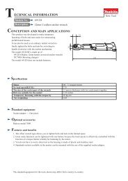
TURRET STOP<br />
Your planer is equipped with a turret stop (Fig. 12) for<br />
repetitive planing of pre-set depths. Stops are set at 0", 1/4",<br />
1/2" and 3/4". Use the 0" setting when planing between 1/8"<br />
and 1/4". To set a planing depth using the turret stop:<br />
• Turn the turret stop until the desired measurement<br />
shows (Figure 12).<br />
• Unlock the headlock lever, and turn the depth<br />
adjustment lever clockwise until it contacts the turret<br />
stop. Do not turn the handle past its stopping point.<br />
• Plane the workpiece and measure the finished<br />
thickness. Make fine adjustments if necessary.<br />
The 3/4" turret stop can be adjusted for other planing<br />
thicknesses. Adjusting the 3/4" turret stop does not affect<br />
the other turret stop settings. To adjust the 3/4" stop for<br />
other thicknesses:<br />
• Unlock the head lock lever (Fig. 8) and turn the<br />
adjustment handle counter-clockwise to raise the cutting<br />
head (Fig. 9) fully.<br />
• From the back of the tool, locate the turret adjustment<br />
bolt shown in Fig. 12. This bolt is set for a 3/4" depth of<br />
cut at the factory. Loosen the jam nut and adjust the<br />
bolt up or down to reach the desired planing depth.<br />
• Turn the depth adjustment lever clockwise until it<br />
contacts the turret stop. Do not turn the handle past its<br />
stopping point.<br />
• Plane your workpiece and measure its finished<br />
thickness. Make additional adjustments, if necessary,<br />
following the steps above.<br />
NOTE: For best results, make several passes, planing both<br />
sides of the workpiece. See “Proper Planing Technique”<br />
below.<br />
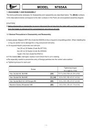
On/Off Switch<br />
To turn the planer on, flip up the switch, as shown in<br />
Figure 13. The planer locks on automatically. To turn the<br />
tool off, press the switch down. A hole is provided in the<br />
switch for insertion of a padlock to lock off the planer<br />
(Figure 13).<br />
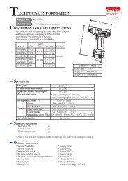
Proper Planing Technique<br />
WARNING: Plane only wood that is free from foreign<br />
objects, with no loose knots and as few tight knots as<br />
possible. Do not plane wood that is severely warped,<br />
twisted, knotted or bowed.<br />
Your planer works best on lumber with at least one flat<br />
surface. If both sides of your workpiece are rough, use a<br />
jointer to level one surface.<br />
MATERIAL<br />
REMOVAL<br />
GAUGE<br />
MATERIAL<br />
REMOVAL<br />
SCALE<br />
FIG. 11<br />
TURRET<br />
ADJUSTMENT BOLT<br />
TURRET STOP<br />
PADLOCK<br />
HOLE<br />
FIG. 13<br />
SWITCH<br />
MATERIAL<br />
REMOVAL GAUGE<br />
FIG. 12<br />
4<br />
3 4<br />
1/8<br />
3/32<br />
1/16<br />
1/32<br />
0<br />
KEEP HANDS<br />
AWAY FROM<br />
CUTTER HEAD.<br />
FIG. A<br />
BOWED WOOD WILL BE FLATTENED BY<br />
FEED ROLLERS AND CUTTERHEAD…<br />
FIG. B<br />
FIG. 14<br />
DIRECTION<br />
OF FEED<br />
TOP FLAT<br />
BOTTOM FLAT<br />
…BUT BOW WILL RETURN<br />
AFTER WOOD IS PLANED<br />
R