DEWALT Industrial Tool Co., 701 East Joppa Road, Baltimore, MD ...
DEWALT Industrial Tool Co., 701 East Joppa Road, Baltimore, MD ...
DEWALT Industrial Tool Co., 701 East Joppa Road, Baltimore, MD ...

You also want an ePaper? Increase the reach of your titles
YUMPU automatically turns print PDFs into web optimized ePapers that Google loves.
English<br />
remove the bow, use a jointer.<br />
Planing<br />
After making all adjustments, turn the tool on and wait until<br />
the knives reach full speed. The workpiece should not be in<br />
contact with the feed rollers or the cutterhead when the tool<br />
is switched on.<br />
Feed wood into the planer as shown in Figure 14. Do not<br />
force wood into the cutterhead. Let the feed rollers<br />
determine how fast the wood is planed.<br />
Adjustments<br />
Changing Knives<br />
REMOVING KNIVES<br />
Your planer is equipped with two knives attached to a<br />
rotating cutterhead. To remove the knives:<br />
1) Turn off and unplug planer. Lift the headlock lever to the<br />
up, or unlocked position.<br />
2) Adjust the depth of cut until the scale reads about 3".<br />
This will ensure ample room to change the knives.<br />
3) Remove the two allen screws near the tool tray, shown in<br />
Figure 15. Carefully lift off the dust chute. CAUTION:<br />
Removing the dust chute leaves the knives exposed.<br />
4) If the eight bolts shown in Figure 16 are not visible,<br />
carefully rotate the cutterhead using a small piece of<br />
scrap wood. Keep your fingers away from the<br />
cutterhead until the eight bolts are visible.<br />
5) When the eight bolts shown in Figure 16 are positioned<br />
as shown, ensure the cutterhead lock lever is in its<br />
locked position and the cutterhead is stable. The knives<br />
will also lock, preventing any further rotation.<br />
6) Using the supplied L-shaped wrench, loosen, but do<br />
not remove the two end bolts shown in Figure 17.<br />
7) Carefully remove the middle six bolts. WARNING:<br />
The knife is spring loaded, and may move toward you<br />
when the six bolts are removed.<br />
8) Press the cutterhead lock lever (Figure 18) down toward<br />
the knife and gently roll the cutterhead backward until<br />
the knife can be removed.<br />
9) Press the cutterhead lock lever (Figure 18) down and<br />
roll the cutterhead until the other knife assembly is<br />
visible. Remove this knife following the steps above.<br />
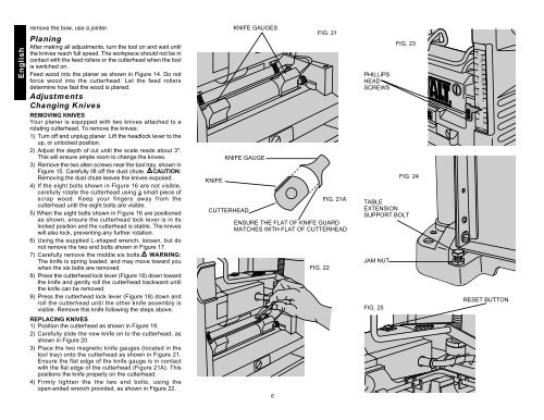
REPLACING KNIVES<br />
1) Position the cutterhead as shown in Figure 19.<br />
2) Carefully slide the new knife on to the cutterhead, as<br />
shown in Figure 20.<br />
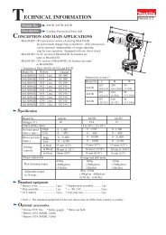
3) Place the two magnetic knife gauges (located in the<br />
tool tray) onto the cutterhead as shown in Figure 21.<br />
Ensure the flat edge of the knife gauge is in contact<br />
with the flat edge of the cutterhead (Figure 21A). This<br />
positions the knife properly on the cutterhead.<br />
4) Firmly tighten the the two end bolts, using the<br />
open-ended wrench provided, as shown in Figure 22.<br />
KNIFE<br />
KNIFE GAUGES<br />
KNIFE GAUGE<br />
CUTTERHEAD<br />
FIG. 21<br />
FIG. 22<br />
FIG. 21A<br />
ENSURE THE FLAT OF KNIFE GUARD<br />
MATCHES WITH FLAT OF CUTTERHEAD<br />
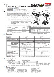
PHILLIPS<br />
HEAD<br />
SCREWS<br />
TABLE<br />
EXTENSION<br />
SUPPORT BOLT<br />
JAM NUT<br />
FIG. 25<br />
FIG. 23<br />
FIG. 24<br />
R<br />
RESET BUTTON<br />
6