KTRRU-052.204 – KTRRU-052.203 –
KTRRU-052.204 – KTRRU-052.203 –
KTRRU-052.204 – KTRRU-052.203 –

Create successful ePaper yourself
Turn your PDF publications into a flip-book with our unique Google optimized e-Paper software.
<strong>KTRRU</strong>-<strong>052.204</strong> <strong>–</strong><br />
<strong>KTRRU</strong>-<strong>052.203</strong> <strong>–</strong><br />
mit Aus(ZwangZu)/Tag/ECO-Schalter / with “OFF (forced switch-off)/day/ECO switch”<br />
avec commutateur du type «Arrêt (coupure forcée) / Jour / ECO»<br />
ohne Schalter / without this switch / sans commutateur de ce type<br />
Elektronischer Unterputz-Klimaregler im Flächenschalterrahmen mit<br />
Taupunktaufschaltung zur Regelung von Kühldecken<br />
Flush-framed electronic climate controller with dew point signal addition<br />
for the control of cooling ceilings<br />
Régulateur électronique conçu pour l’installation encastrée avec des cadres de<br />
recouvrement plats, type avec adjonction d’un signal de point de rosée pour la régulation<br />
des opérations climatiques exécutées par des plafonds réfrigérants<br />
Sicherheitshinweis!<br />
Dieses Gerät darf nur durch eine Elektrofachkraft geöffnet und gemäß dem entsprechenden<br />
Schaltbild im Gehäusedeckel / auf dem Gehäuse / in der Bedienungsanleitung installiert<br />
werden. Dabei sind die bestehenden Sicherheitsvorschriften zu beachten.<br />
Achtung! Der Betrieb in der Nähe von Geräten, welche nicht den EMV-Richtlinien entsprechen,<br />
kann zur Beeinflussung der Gerätefunktionen führen. Nach der Installation ist<br />
der Betreiber in die Funktion und Bedienung der Regelung einzuweisen. Die Bedienungsanleitung<br />
muss für Bedien- und Wartungspersonal an frei zugänglicher Stelle aufbewahrt<br />
werden.<br />
D<br />
Safety information!<br />
GB<br />
No persons other than expert electricians only must open this device in due compliance<br />
with the wiring diagram shown in the housing cover / on the housing / represented in the<br />
corresponding operating instructions. All expert electricians committed to the execution<br />
of any such works must comply with the relevant safety regulations currently operative<br />
and in force.<br />
Caution! The operation of the controller in the vicinity of other devices that do not<br />
comply with the EMC directives may affect its functions. The company charged with the<br />
installation of the device must, after the completion of the installation works, instruct the<br />
user of the control system into its functions and in how to operate it correctly. These<br />
operating instructions must be kept at a place that can be accessed freely by the operating<br />
and/or servicing personnel in charge.<br />
1. Anwendung 1. Application<br />
Dieser Regler wurde speziell zur Heiz-/Kühlregelung in 2- und 4-Rohr-Leitungssystemen<br />
für Hotel-, Wohn- und Geschäftsräume entwickelt und kann bis zu 5 Ventilantriebe<br />
(24V~, stromlos geschlossen) je Ausgang ansteuern. Besonders geeignet ist der <strong>KTRRU</strong><br />
durch die Möglichkeit der Taupunktüberwachung zur Kühldeckenregelung. Für andere,<br />
vom Hersteller nicht vorherzusehende Einsatzgebiete, sind die dort gültigen Sicherheitsvorschriften<br />
zu beachten. Eignung hierfür siehe Punkt 11. Gewährleistung.<br />
This controller has been specially devised for the dew point signal addition based control<br />
of the heating and cooling operations performed in 2 and 4-pipe systems that exist in<br />
hotel rooms, living spaces and business premises. The device is able to trigger up to 5<br />
valve drives per output (24V, normally closed). The <strong>KTRRU</strong> is, owing to its dew point<br />
monitoring function, particularly suited for the control of cooling ceilings. Regarding<br />
other applications not to be foreseen by the manufacturer of this device, the safety standards<br />
concerning these applications need to be followed and adhered to. Regarding the<br />
aptitude of the device for any such other application, please refer to section 11. herein<br />
(Warranty).<br />
2. Funktionen allgemein 2. General description of the functions of the device<br />
Der <strong>KTRRU</strong> misst mit einem internen Fühler die Raumtemperatur und aktiviert bei Abweichung<br />
zum eingestellten Sollwert die Heizung bzw. Kühlung. Der Regler wird mittels<br />
Steckbrücke (Jumper 1, vgl. Pkt. 9) an das Leitungssystem, 2-Rohr oder 4-Rohr (Werkseinstellung)<br />
angepasst. Im 4-Rohr-Leitungssystem ohne Change-Over-Funktion wird der<br />
Regler im Heiz-/Kühlbetrieb mit neutraler Zone betrieben, so dass bei gleichzeitiger Bereitstellung<br />
von Heiz- und Kühlenergie innerhalb eines Gebäudes verschiedene Räume<br />
beheizt und gekühlt werden können.<br />
2.1. Heiz-/Kühlumschaltung im 4-Rohrsystem (Change-Over-Funktion)<br />
Diese Funktion muss mittels Steckbrücke (Jumper 2, vgl. Pkt. 9) ausgewählt werden.<br />
Wenn das Gebäude nicht gleichzeitig mit Heiz- und Kühlmedium versorgt wird, kann<br />
über einen externen Kontakt (Change-Over-Kontakt) die nicht mit Heiz- oder Kühlmedium<br />
versorgte Seite gesperrt werden. So wird je nach Kontaktstellung der Kühlausgang<br />
in der Heizsaison oder der Heizausgang in der Kühlsaison nicht angesteuert. Durch<br />
diese Funktion werden die Ventilantriebe der gesperrten Seite geschont und Energie eingespart.<br />
Kontakt geöffnet = Kühlbetrieb (Heizkreis gesperrt), Kontakt geschlossen =<br />
Heizbetrieb (Kühlkreis gesperrt).<br />
2.2. Heiz-/Kühlumschaltung im 2-Rohrsystem (Change-Over-Funktion)<br />
Im 2-Rohrbetrieb wird der Regler mit einem gemeinsamen Heiz-/Kühlausgang betrieben,<br />
der über einen externen Kontakt (Change-Over-Kontakt) umgeschaltet wird. So ist es<br />
möglich, eine zentrale Umschaltung für alle Regler zu realisieren. Kontakt geöffnet =<br />
Kühlbetrieb, Kontakt geschlossen = Heizbetrieb. Verdrahtung siehe Punkt 10.<br />
2.3. Kühlunterbrechung bei Kondensatbildung durch optionalen Taupunktsensor<br />
Die Funktion kühlen kann bei Kondensatbildung durch einen optionalen externen Sensor<br />
unterbrochen werden. Der Taupunktsensor muss an den Ort mit der größten<br />
Taupunktwahrscheinlichkeit an den Kühlkreislauf montiert werden. Kann dieser<br />
Montageort nicht eindeutig festgelegt werden, besteht die Möglichkeit, bis zu 5<br />
Taupunktsensoren parallel an den Regler anzuschließen. Vorzugsweise sollten die Taupunktsensoren<br />
am in den Raum führenden Zulauf und/oder im Fensterbereich montiert<br />
werden. Siehe auch Punkt 6. Zubehör.<br />
2.4. Energiesparfunktion (ECO Betrieb)<br />
Durch einen externen Kontakt (ECO Kontakt) oder den Schalter kann die Energiesparfunktion<br />
ausgelöst werden. Wird diese Funktion gewählt, wird im Heizbetrieb auf eine um 3K<br />
geringere und im Kühlbetrieb auf eine um 3K höhere Temperatur geregelt. So kann bei<br />
nicht belegten bzw. ungenutzten Räumen oder Etagen per Hand oder zeitgesteuert über<br />
einen Uhrenkontakt eine zentrale Energieeinsparung realisiert werden. Verdrahtung siehe<br />
Punkt 10.<br />
Kontakt geschlossen = ECO Funktion, Kontakt offen = Normalbetrieb<br />
2.5. Schalterfunktionen<br />
Der <strong>KTRRU</strong>-<strong>052.204</strong> verfügt über einen „Aus(ZwangZu)/Tag/ECO“-Schalter. In Stellung<br />
„Aus“ wird der Frostschutz durch den Regler gewährleistet.<br />
2.6. Frostschutzfunktion<br />
Steht der Schalter des <strong>KTRRU</strong>-<strong>052.204</strong> in Stellung „Aus“ (ZwangZu), wird weiterhin die<br />
Raumtemperatur überwacht und bei Frostgefahr kleiner 5°C die Ventile zwangsgeöffnet.<br />
Die Frostschutzüberwachung ist unabhängig von den gewählten Funktionen und Stellungen<br />
der Steckbrücken in Schalterstellung „Aus“ aktiv. Bei Auslösung werden die Ventile<br />
geöffnet und die Aktivierung durch rotes Leuchten der Lampe angezeigt.<br />
The <strong>KTRRU</strong> measures, based on the data that are delivered to it by an internal sensor, the<br />
temperature that exists in the related room and, in the event a deviation of the actual<br />
value with regard to the set value is detected, triggers the activation of the heating or<br />
cooling installation as needed. A jumper (jumper 1, see section 9.) enables to adjust the<br />
controller to the pipe system that is to be controlled, scilicet a 2-pipe or 4-pipe system<br />
(factory setting). A neutral zone between the heating and cooling control ranges of<br />
change-over function-less devices that are employed for the control of 4-pipe systems<br />
enables, so long as the required heating and cooling energy is being provided, the<br />
heating and cooling of different rooms within the same building.<br />
2.1. Heating / cooling change-over function for the control of 4-pipe systems<br />
Setting a jumper (jumper 2, see section 9.) enables to select this function. In the case<br />
the related building can only be supplied with either heating or cooling agent, the side of<br />
the system that is not supplied with one of these media at that time, can be disabled by<br />
means of an external contact (change-over contact). Depending on the position of the<br />
switch, either the cooling output during the heating season or the heating output during<br />
the cooling season remains thus untriggered. This function protects the valve drives on<br />
the disabled side of the system and helps save energy. Contact open = operation in<br />
cooling mode (heating circuit disabled); contact closed = operation in heating mode<br />
(cooling circuit disabled).<br />
2.2. Heating / cooling changeover function for the control of 2-pipe systems<br />
A joint heating/cooling output, the changeover of which is triggered by means of an<br />
external contact (changeover contact), enables to use the device for the control of 2-pipe<br />
systems. All controllers employed for the management of the system can, based on this<br />
function, be changed over from one central point. Contact open = operation in cooling<br />
mode; contact closed = operation in heating mode. As for cabling, see section 10.<br />
2.3. Interruption of the cooling operation in the event of the formation of condensate<br />
based on the operation of a special dew point sensor (optional)<br />
Optionally, an external sensor can be connected in addition that enables to trigger the<br />
interruption of the cooling mode operation in the event it detects the formation of condensate.<br />
This dew point sensor must be installed at the place within the cooling circuit<br />
where the formation of condensate (dew point) is most likely. If this place of installation<br />
cannot be defined clearly, a total of up to 5 dew point sensors can be connected in parallel<br />
to the controller. Preferably, the required dew point sensors should be installed on the<br />
supply line that leads into the related room and/or should be installed close to the<br />
windows. Regarding thereto, please see also section 6.,“Accessories”.<br />
2.4. Energy economizing function (ECO mode)<br />
The economizing function can be triggerd via an external contact (ECO contact) or via a<br />
switch provided for this purpose. a temperature decrease of 3K is effected while operating<br />
in heating mode and a temperature increase of 3K admitted while operating in cooling<br />
mode. With currently unoccupied or unused rooms or floors the saving of energy<br />
can, from a central point, thus either be controlled manually or, based on a time contact,<br />
in a time-controlled manner. As for cabling, see section 10.<br />
Contact closed = ECO function; contact opened = normal operating mode.<br />
2.5. Switch functions<br />
The <strong>KTRRU</strong>-<strong>052.204</strong> has been equipped with an “OFF (forced switch-off) / day / ECO”<br />
switch. Even if this switch is in OFF position, the controller continues directing the<br />
related antifreezing operations.<br />
2.6. Antifreezing function<br />
Even if the switch of the <strong>KTRRU</strong>-<strong>052.204</strong> has been set to OFF (forced switch-off), the<br />
supervision and control of the room temperature will be continued. Once the system<br />
detects that frost is imminent, i.e. if temperatures fall below 5°C, the valves are opened<br />
forcibly. Even it the switch has been set to OFF, the frost protection monitoring continues<br />
to be active independent of the actually selected functions or jumper positions. The triggering<br />
of the antifreezing function results in the opening of the valves, the activation of<br />
which is indicated by the red indicating lamp.<br />
Stand 10.2010 (10/112) 1 5 21 252 04
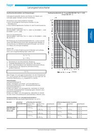
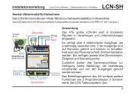
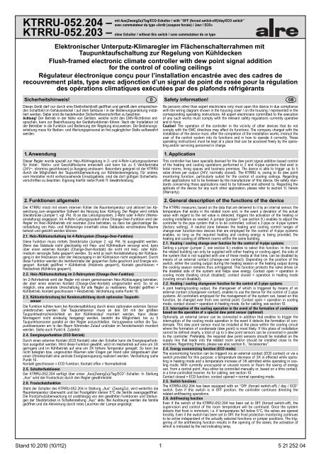
2.7. Begrenzung des Einstellbereichs<br />
Um den Einstellbereich einzuengen, wird der sich unter dem Einstellknopf befindliche<br />
Stift abgezogen und die Einstellfahnen verstellt (rot für maximal und blau für minimal<br />
mögliche Einstellung). Anschließend wird der Stift wieder eingesteckt und somit die Begrenzungen<br />
arretiert.<br />
Einstellfahne für<br />
maximalen<br />
Temperaturwert<br />
Einstellfahne für<br />
minimalen<br />
Temperaturwert<br />
2.7. Suppression of the setting range<br />
The setting pins located underneath of the adjusting knob enable to delimit the setting<br />
range of the controller mechanically. To enable this and to fix the new limitations, the<br />
adjusting knob must be removed by pulling it off and, after the adjustment of the related<br />
setting pins (red for max. and blue for min. possible setting) be put on again.<br />
Pin for the setting<br />
of the max.<br />
temperature value<br />
Pin for the setting<br />
of the min.<br />
temperature value<br />
3. Anzeigen<br />
Der Regler verfügt über eine Lampe zur Anzeige des Regelzustandes.<br />
rot = heizen<br />
blau = kühlen<br />
gelb = Kühlunterbrechung durch Kondensatbildung<br />
rot in Schalterstellung „Aus“ = Frostschutzauslösung<br />
4. Montage<br />
Je nach Gerätetyp oder Verpackungsgröße wird das Gerät entweder geschlossen oder<br />
der schnelleren Montage wegen geöffnet ausgeliefert. Das Gerät mit dem<br />
50 x 50 mm Gehäusedeckel ist mittels Zwischenrahmens der Schalterhersteller nach<br />
DIN 49075 in nahezu alle Schalterprogramme integrierbar. Das Gerät mit dem<br />
55 x 55 mm Gehäusedeckel ist ebenfalls für diverse Schalterprogramme geeignet. Bei<br />
Mehrfachrahmen ist der Regler immer an unterster Stelle zu montieren. Der Regler ist<br />
zur Montage in die UP-Dose bestimmt und darf nicht direkt Wärme- oder Kältequellen<br />
ausgesetzt werden. Es ist darauf zu achten, dass der Regler auch rückseitig keiner<br />
Fremderwärmung oder -kühlung, z.B. bei Hohlwänden durch Zugluft oder Steigleitungen<br />
ausgesetzt wird.<br />
Zum Öffnen des Reglers ist die Schraube nach Abziehen des Einstellknopfes zu lösen<br />
und die Reglerkappe inklusive Rahmen abzunehmen. Nach elektrischem Anschluss und<br />
Montage in die UP-Dose ist der Regler in umgekehrter Reihenfolge wieder zu schließen.<br />
Siehe auch Punkt 8.<br />
4. Mounting<br />
The controller is, depending on the type version of the device or size of the package used<br />
or it, either delivered in closed or, in order to facilitate its fast installation, also in opened<br />
condition. The device with the 50 x 50 mm housing cover can be integrated into almost all<br />
currently available flush switch installation frame systems when using DIN 49075 compliant<br />
intermediate frames. The device with the 55 x 55 mm housing cover too can be<br />
combined with different commercially available switch lines. If using multiple frames, the<br />
controller must always be mounted in the lowest position. The device is determined for the<br />
installation in an UP box and must not be exposed directly to any heat or cold sources.<br />
Care must be taken to ensure that it is not exposed to the influence of heat or cold sources<br />
that warm or cool the device at its back (through air flows in cavity walls or the temperatures<br />
radiated by ascending pipelines, f. ex.).<br />
To open the controller, remove the adjusting knob first, then loosen the screw and remove<br />
both the controller cap and the frame. After its electrical connection and installation in the<br />
UP box, the closing of the controller takes place in inverse order (see section 8.).<br />
5. Technische Daten 5. Technical data<br />
Versorgungs- und Schaltspannung: 24V, 50/60Hz, Sicherheitskleinspannung Supply- and switching voltage: 24V, 50/60Hz, safety extra low voltage<br />
Ausgänge / Schaltleistung:<br />
2 x Relaiskontakte je 1A<br />
Outputs / switching capacity: 2 x relay contacts, 1A each<br />
(max. 5 Ventilantriebe je Ausgang)<br />
(max. 5 valve drives per output)<br />
Regelbereich: 21°C ±8K<br />
Control range: 21°C ±8K<br />
Schaltdifferenz heizen:<br />
< 1K<br />
Switching difference (heating): < 1K<br />
Schaltdifferenz kühlen:<br />
< 1K<br />
Switching difference (cooling): < 1K<br />
Neutrale Zone:<br />
+/-1K<br />
Neutral zone:<br />
+/-1K<br />
Frostschutzauslösung: < 5°C<br />
Anti-frost triggering: < 5°C<br />
ECO-Zone:<br />
±3K fest eingestellt<br />
ECO zone:<br />
±3K réglée fixe<br />
Skala:<br />
Schwellpfeile rot/blau, Wohlfühlpunkt<br />
Scale:<br />
red and blue swelling arrows with well-being<br />
Fühler:<br />
NTC, intern<br />
point mark<br />
Elektrischer Anschluss: Schraubklemmen 0,5 … 2,5 mm 2<br />
Sensor:<br />
NTC, internal type<br />
Leistungsaufnahme:<br />
0,6W (1,0VA)<br />
Elektrischer Anschluss: terminal screws (0,5 … 2,5 mm 2 )<br />
Schutzart:<br />
IP30 nach entsprechender Montage<br />
Power consumption:<br />
0,6W (1,0VA)<br />
Schutzklasse:<br />
III<br />
Degree of protection:<br />
IP 30 (after corresponding installation)<br />
Montage:<br />
in UP-Dose Ø 55 mm<br />
Protection class:<br />
III<br />
Umgebungstemperatur: 0 … 40°C<br />
Installation:<br />
in an UP box (Ø 55 mm)<br />
Lagertemperatur:<br />
-20 … +70°C<br />
Ambient temperature: 0 … 40°C<br />
Zulässige Luftfeuchtigkeit:<br />
max. 95% r.H. nicht kondensierend<br />
Storage temperature:<br />
-20 … +70°C<br />
Gehäusematerial und Farbe: Polycarbonat (PC), reinweiß<br />
Admissible air moisture:<br />
max. 96% r.h., non condensing<br />
(ähnlich RAL 9010) oder cremeweiß<br />
Housing material and colour: polycarbonate (PC), pure white<br />
(ähnlich RAL1013)<br />
(similar to RAL 9010)<br />
Ausstattung:<br />
mech. Bereichseinengung<br />
or cream white (similar to RAL1013)<br />
Aus(ZwangZu)/Tag/ECO-Schalter bei<br />
Equipment:<br />
mech. Bereichseinengung<br />
<strong>KTRRU</strong>-<strong>052.204</strong><br />
mechanical range suppression, model<br />
<strong>KTRRU</strong>-<strong>052.204</strong> with OFF<br />
(forced switch-off) / day / ECO switch<br />
6. Zubehör (optional) 6. Accessories (optional)<br />
3. Indicators<br />
The controller has been equipped with a lamp for the indication of the control condition.<br />
red = heating<br />
blue = cooling<br />
yellow = interruption of the cooling operation due to the formation of condensate<br />
red in switch position OFF = anti-frost triggering<br />
Taupunktsensoren TPS 1, TPS 2 und TPS 3. Dew point sensors type TPS 1, TPS 2 and TPS 3.<br />
7. Verwendete Symbole<br />
7. Explanation of symbols<br />
Bedien- und Anzeigesymbole<br />
Normalbetrieb<br />
ECO-Betrieb<br />
Regelung Aus (Frostschutz)<br />
Heizung EIN<br />
Kühlung EIN<br />
Wohlfühltemperatur ca.21°C<br />
ECO<br />
Klemmensymbole<br />
Heizen / Kühlen /<br />
Heizen<br />
Phase Betriebsspannung V+<br />
Masse Betriebsspannung<br />
Heiz-/Kühl-Umschaltung<br />
H / C<br />
ECO-Kontakt<br />
ECO<br />
Taupunktsensor<br />
Masse Fühler<br />
F<br />
Control and indicating symbols<br />
Normal operation<br />
ECO mode<br />
Control OFF (frost protection)<br />
Heating ON<br />
Cooling ON<br />
Comfort temperature (approx. 21°C)<br />
ECO<br />
Terminal symbols<br />
Heating / Cooling /<br />
Heating<br />
Phase V+<br />
Operating voltage<br />
Heating / cooling changeover H / C<br />
ECO contact<br />
ECO<br />
Dew point sensor<br />
Sensor mass<br />
F<br />
Cosignes de sécurité!<br />
Uniquement des personnes qualifiées en matière d’électricité doivent ouvrir ce dispositif<br />
en conformité avec le schéma des connexions représenté dans le couvercle du boîtier /<br />
apposé sur le boîtier / représenté dans les notices d’instructions correspondantes. Tous<br />
électriciens spécialisés chargés de l’exécution de tels travaux doivent se conformer aux<br />
prescriptions de sécurité actuellement en vigueur s’y rapportant. Attention! L’opération<br />
dans les environs d’autres dispositifs qui ne répondent pas à la directive EMC peut<br />
porter préjudice au fonctionnement du dispositif. Les instructions de service sont à<br />
garder à un lieu librement accessible pour les opérateurs et hommes de service.<br />
F<br />
1. Application<br />
Ce régulateur a été spécialement conçu pour le contrôle des opérations de chauffage ou<br />
de refroidissement exécutées par des systèmes à 2 ou 4 conduites installés dans des<br />
hôtels, des habitations et des bureaux. Le dispositif permet de contrôler un nombre de<br />
jusqu’à 5 entraînements de soupape (24V~/4, types de soupapes normalement fermées)<br />
par sortie. Le <strong>KTRRU</strong> convient, grâce à sa fonction de surveillance du point de rosée, en<br />
particulier pour le contrôle de plafonds réfrigérants. Concernant des autres applications<br />
pas à prévoir par le fabricant de ce dispositif, les standards de sécurité se rapportant à<br />
ces applications sont à respecter. En ce qui concerne l’aptitude ou l’approbation du dispositif<br />
pour des telles applications, veuillez également faire attention aux informations de<br />
garantie dans chapitre 11. (Garantie) dans cette notice d’instructions.<br />
2
2. Description générale des fonctions du dispositif<br />
Le <strong>KTRRU</strong> mesure, sur la base des données délivrées par un détecteur interne, la température<br />
qui existe dans le local correspondant et déclenche, dans le cas ou il détecte une déviation<br />
vis-à-vis de la valeur de consigne préréglée, l’activation de l’installation de chauffage ou<br />
de refroidissement selon besoin. Des ponts enfichables (pont enfichable 1, cf. chapitre 9.)<br />
permettent l’adaptation du régulateur aux systèmes tubulaires à 2 ou 4 (ajustage d’usine)<br />
conduites. Une zone neutre entre les plages de réglage des dispositifs sans contact de permutation<br />
utilisés pour le contrôle de systèmes à 4 conduites permet, tant que l’alimentation<br />
des énergies de chauffage et de refroidissement continue, le chauffage et refroidissement de<br />
différentes salles ou chambres dans le même bâtiment.<br />
2.1. Fonction de permutation chauffage/refroidissement pour le contrôle de systèmes à 4<br />
conduites<br />
La sélection de cette fonction se fait par moyen de la mise d’un pont enfichable (pont enfichable<br />
2,cf.chapitre 9.).Lorsque le bâtiment peut être alimenté uniquement soit de médium<br />
de chauffage ou de médium de refroidissement, le côté du système ne pas alimenté avec un<br />
de ces médias à ce moment, peut être immobilisé par l’actionnement d’un contact de permutation<br />
externe. En fonction de la position du commutateur, la sortie de refroidissement ne<br />
sera donc pas déclenchée durant la saison de chauffage et, par contre, la sortie de chauffage<br />
ne pas durant la saison de refroidissement. Cette fonction permet d’épargner les entraînements<br />
des soupapes installés dans le système passagèrement immobilisé et de faire des<br />
économies d’énergie. Contact ouvert = opération en mode de service «refroidissement» (circuit<br />
de chauffage en condition immobilisée); contact fermé = opération en mode de service<br />
«chauffage» (circuit de refroidissement immobilisé).<br />
2.2. Fonction de permutation chauffage/refroidissement pour le contrôle de systèmes à 2<br />
conduites<br />
Une sortie commune «chauffage/refroidissement», dont la permutation est déclenchée par<br />
moyen d’un contact de permutation externe, permet l’utilisation du dispositif pour le contrôle<br />
de systèmes à 2 conduites. Tous régulateurs utilisés pour le pilotage du système peuvent,<br />
sur la base de cette fonction, donc être permutés à partir d’un point central. Contact ouvert =<br />
opération en mode de service «refroidissement»; contact fermé = opération en mode de<br />
service «chauffage». Concernant le câblage, cf. pargraphe 10.<br />
2.3. Interruption de l’opération durant le mode de fonctionnement «refroidissement»<br />
dans le cas d’une formation d’eau de condensation piloté par l’opération d’un détecteur<br />
du point de condensation externe (facultatif)<br />
Facultativement, un détecteur externe peut être raccordé en plus qui permet de déclencher<br />
l’interruption de l’opération en mode de fonctionnement «refroidissement» dans le cas où il<br />
détecterait une formation de l’eau de condensation. Ce détecteur du point de condensation<br />
doit, afin de garantir le fonctionnement parfait du dispositif, être installé le plus proche que<br />
possible au lieu sur le circuit frigorifique où la formation de l’eau condensée aura lieu le plus<br />
vraisemblablement (point de rosée). Pour des cas où il n’est possible de définir clairement ce<br />
lieu d’installation, le dispositif permet le raccordement parallèle de jusqu’à 5 détecteurs du<br />
point de condensation. De préférence, il faudrait installer les détecteurs du point de condensation<br />
requis sur la conduite d’alimentation qui mène dans la salle correspondante et/ou les<br />
installer près des fenêtres. Voir aussi chapitre 6. (Accessoires).<br />
2.4. Fonction économisante concernant la consommation d’énergie (mode de service ECO)<br />
Cette fonction peut être déclenchée par un contact externe (contact ECO) ou par un commutateur<br />
spécialement prévu à cet effet. Cette fonction une fois sélectionnée, un abaissement de<br />
la température sera effectué durant l’opération en mode de service «chauffage» par 3K et une<br />
augmentation de la température par 3K durant l’opération en mode de service «refroi-dissement».<br />
Avec des salles, locaux ou étages actuellement inoccupés ou inutilisés, l’économisation<br />
d’énergie peut donc, à partir d’un point central, être contrôlé soit manuellement ou, sur la<br />
base d’un contact d’horloge, de manière temporisée. Concernant le câblage, cf. pargraphe 10.<br />
Contact fermé = fonctionnement en mode de service ECO, contact ouvert = service normal.<br />
2.5. Fonctions du commutateur<br />
Le <strong>KTRRU</strong>-<strong>052.204</strong> est doté d’un commutateur sélecteur spécial du type «Arrêt (coupur<br />
forcée) / Jour / ECO». Lorsque le commutateur est en position «arrêt», le régulateur garantit<br />
le maintien de la fonction antigel.<br />
2.6. Fonction antigel<br />
Lorsque l’interrupteur du <strong>KTRRU</strong>-<strong>052.204</strong> est en positon ARRET (coupure forcée), la surveillance<br />
de la température ambiante sera toutefois continuée et les soupapes forcément ouvertes<br />
en cas du danger de gel (c’est-à-dire en cas de températures en dessous de 5°C). Le témoin<br />
lumineux rouge sert pour l’indication du déclenchement de la fonction antigel.<br />
2.7 Resserrage de domaine<br />
La plage de réglage peut être limitée mécaniquement au moyen des éléments mobiles d’ajustage<br />
que se trouvent en dessous du bouton de réglage. Pour faire ça, il faut d’abord enlever le<br />
bouton en le retirant. L’ajustage (fixation) des éléments de butée (rouge pour température<br />
max. et bleu pour température min.) une fois terminée, le bouton peut encore être replacé.<br />
Broche pour le réglage<br />
de la valeur de<br />
température maximale<br />
Broche pour le réglage<br />
de la valeur de<br />
température minimale<br />
3. Voyants lumineux<br />
Le régulateur est doté d’un voyant pour l’indication de l’état de réglage<br />
Rouge = chauffer<br />
Bleu = refroidir<br />
Jaune = interruption de l’opération durant mode de fonctionnement «refroidissement»<br />
par raison de formation de l’eau condensée Allumage rouge avec le commutateur en<br />
position d’ARRET = déclenchement de la fonction antigel<br />
4. Montage<br />
Le dispositif est, selon son type ou la taille du paquet utilisé pour son emballage, livré<br />
soit en condition fermée ou, pour faciliter son installation rapide, en condition ouverte.<br />
Le dispositif avec le couvercle de la taille 50 x 50 mm peut, lors de l’utilisation d’un cadre<br />
intermédiaire en conformité avec DIN 49075, être intégré dans presque tous les systèmes<br />
de cadres de recouvrement actuellement en vente. Le modèle avec le couvercle de la<br />
taille 55 x 55 mm aussi convient pour l’intégration dans des commutateurs de diverses<br />
gammes. Lors de l’utilisation de cadres multiples, il faut toujours monter le régulateur à<br />
la position la plus basse. Le dispositif est prévu pour l’installation dans une boîte encastrée<br />
et ne doit pas être exposé à l’influence de sources de chaleur ou de froid. Il faut<br />
également veiller à ce que le dispositif ne soit pas exposé à l’influence de sources de<br />
chaleur ou de froide, qui le chauffent ou refroidissent à sa face arrière (par des courants<br />
d’air dans des murs creux ou par les températures répandues par des conduites montantes,<br />
par ex.). Pour ouvrir le régulateur, d’abord retirer le bouton de réglage et desserrer<br />
la vis. Ensuite enlever le couvercle du régulateur conjointement avec le cadre de recouvrement.<br />
Pour refermer le régulateur après le raccordement électrique et l’installation du<br />
régulateur dans la boîte encastrée, procéder en ordre inverse (voir chapitre 8.).<br />
5. Caractéristiques techniques<br />
Tension d’alimentation et de commutation:24V, 50/60Hz, tension de sécurité extra réduite<br />
Sorties / puissance de coupure: 2 x contacts de relais (1A en chaque cas)<br />
(max. 5 entraînements des soupapes par sortie)<br />
Plage de réglage: 21°C ±8K<br />
Différentiel chauffage:<br />
< 1K<br />
Différentiel refroidissement:<br />
< 1K<br />
Zone neutre:<br />
+/-1K<br />
Déclenchement antigel: < 5°C<br />
Zone ECO:<br />
±3K, réglée fixe<br />
Echelle:<br />
flèches gonflantes rouge et bleue avec repère<br />
pour l’indication du point de bien-être<br />
Détecteur:<br />
NTC, type interne<br />
Raccordement électrique: bornes à vis (0,5 … 2,5 mm 2 )<br />
Puissance absorbée:<br />
0,6W (1,0VA)<br />
Type de protection:<br />
IP 30 (après installation correspondante)<br />
Indice de protection:<br />
III<br />
Installation:<br />
dans une boîte encastrée (Ø 55 mm)<br />
Température ambiante: 0 … 40°C<br />
Température de stockage:<br />
-20 … +70°C<br />
Humidité de l’aire admissible:<br />
max. 95 % r.h., non condensant<br />
Matériau du boîtier et couleur: polycarbonate (PC), blanc alpin<br />
(pareil à RAL 9010)<br />
ou blanc crème (pareil à RAL1013)<br />
Equipement:<br />
limitation de la plage de réglage mécanique;<br />
modèle <strong>KTRRU</strong>-<strong>052.204</strong> avec commutateur du<br />
type «Arrêt (coupure forcée) / Jour / ECO»<br />
6. Accessoires (facultatif<br />
Détecteurs du point de rosée types TPS 1, TPS 2 et TPS 3.<br />
7. Symboles utilisés<br />
Symbole de commande et d’indication<br />
Fonctionnement normal<br />
Opération en mode de service «ECO» ECO<br />
Réglage ARRET (protection antigel)<br />
Chauffage MARCHE<br />
Refroidissement MARCHE<br />
Température de bien-être (env. 21°C)<br />
Symboles bornier<br />
Chauffage / refroidissement /<br />
Chauffage<br />
Phase V+<br />
Tension de service<br />
Permutation chauffage/refroidissement H / C<br />
Contact ECO<br />
ECO<br />
Détecteur du point de rosée<br />
Masse du détecteur<br />
F<br />
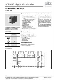
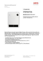
8. Installations- und Montagehinweise / Installation and mounting information / Précision d’installation et de montage<br />
Regler 50 x 50 mit alre-Rahmen<br />
Controller (50 x 50) with alre type frame<br />
Régulateur (50 x 50) avec cadre de recouvrement type alre<br />
Regler 50 x 50 mit Beispiel-Rahmen und Zwischenrahmen<br />
Controller (50 x 50) with sample frame and intermediate frame<br />
Régulateur (50 x 50) avec cadre de recouvrement et cadre intermédiaire<br />
(exemple)<br />
3<br />
Regler 55 x 55 mit Beispiel-Rahmen<br />
Controller (55 x 55) with sample frame<br />
Régulateur (50 x 50) avec cadre de recouvrement (exemple)
9. Justageeinstellungen / Adjustment settings / Réglages d’ajustage<br />
Jumper 1:<br />
<strong>–</strong> Brücke links<br />
= 2-Rohrsystem<br />
<strong>–</strong> Brücke rechts<br />
= 4-Rohrsystem<br />
(Werkseinstellung)<br />
Jumper 2:<br />
<strong>–</strong> mit Brücke<br />
= ohne Change-Over-Funktion<br />
im 4-Rohrsystem<br />
(Werkseinstellung)<br />
<strong>–</strong> ohne Brücke<br />
= mit Change-Over-Funktion<br />
im 4-Rohrsystem<br />
Jumper 1:<br />
<strong>–</strong> Jumper in left position<br />
= 2-pipe system<br />
<strong>–</strong> Jumper in right position<br />
= 4-pipe system<br />
(factory setting)<br />
Jumper 2:<br />
<strong>–</strong> with jumper<br />
= without changeover function<br />
when used with 4-pipe systems<br />
(factory setting)<br />
<strong>–</strong> without jumper<br />
= with changeover function<br />
when used with 4-pipe systems<br />
Pont enfichable 1:<br />
<strong>–</strong> Pont enfichable à gauche<br />
= système à 2 conduites<br />
<strong>–</strong> Pont enfichable à droite<br />
= système à 4 conduites<br />
(ajustage d’usine)<br />
Pont enfichable 2:<br />
<strong>–</strong> avec pont enfichable<br />
= sans fonction de permutation<br />
lorsqu’utilisé pour le contrôle de systèmes à 4 conduites<br />
(ajustage d’usine)<br />
<strong>–</strong> sans pont enfichable<br />
= avec fonction de permutation<br />
lorsqu’utilisé pour le contrôle de systèmes à 4 conduites<br />
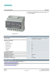
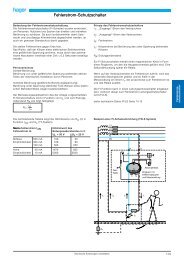
10. Maßzeichnungen und Anschluss-Schaltbilder / Dimensioned drawings and connection diagrams<br />
Dessins cotés et schémas de branchement<br />
Regler 50 x 50 mit alre-Rahmen<br />
Controller (50 x 50) with alre type frame<br />
Régulateur (50 x 50) avec cadre de recouvrement type alre<br />
Regler 50 x 50 mit Beispiel-Rahmen und Zwischenrahmen<br />
Controller (50 x 50) with sample frame and intermediate frame<br />
Régulateur (50 x 50) avec cadre de recouvrement et cadre<br />
intermédiaire (exemple)<br />
Regler 55 x 55 mit Beispiel-Rahmen<br />
Controller (55 x 55) with sample frame<br />
Régulateur (55 x 55) avec cadre de recouvrement (exemple)<br />
Anschluss im 2-Rohr-Leitungssystem (siehe auch<br />
Punkt 9., Jumper 1)<br />
Connection for the control of 2-pipe systems (see<br />
also section 9., Jumper1)<br />
Raccordement pour le contrôle de systèmes à 2<br />
conduites (voir également chapitre 9.,<br />
pont enfichable 1)<br />
Anschluss im 4-Rohr-Leitungssystem (siehe auch Punkt 9.,<br />
Jumper 1)<br />
Connection for the control of 4-pipe systems (see also section<br />
9., Jumper 1)<br />
Raccordement pour le contrôle de systèmes à 4 conduites<br />
(voir également chapitre 9.,<br />
pont enfichable 1)<br />
Achtung! Die Masse der Versorgungsspannung darf nicht mit der Masse der Fühler verbunden werden, ein Zusammenschluss oder<br />
eine Verwechslung führt zur Zerstörung des Reglers.<br />
Caution! The supply voltage ground must not be connected to the sensor mass. An interconnection or a confusion results in the<br />
destruction of the controller!<br />
Attention! Ne pas relier la terre de la tension d’alimentation à la masse des détecteurs, car une connexion résulterait dans la destruction<br />
du régulateur.<br />
Regler 1 / Controller 1<br />
Régulateur 1<br />
Regler 2 / Controller 2<br />
Régulateur 2<br />
····<br />
Regler 20 / Controller 20<br />
Régulateur 20<br />
H/C-Relais<br />
H/C relay<br />
Relais chauff./refroid.<br />
Verdrahtung für Heiz-Kühl-Umschaltung und/oder ECO mehrerer Regler (max. 20 Regler).<br />
Cabling for heating/cooling mode and/or ECO switchover of several controllers (max. 20 controllers).<br />
Câblage pour la commutation entre les modes de services chauffage/refroidissement et/ou ECO de plusieurs régulateurs<br />
(maximum 20 régulateurs).<br />
11. Gewährleistung / Warranty / Garantie<br />
Die von uns genannten technischen Daten wurden unter Laborbedingungen nach allgemein gültigen Prüfvorschriften <strong>–</strong> insbesondere DIN-Vorschriften <strong>–</strong> ermittelt. Nur insoweit werden Eigenschaften<br />
zugesichert. Die Prüfung der Eignung für den vom Auftraggeber vorgesehenen Verwendungszweck bzw. den Einsatz unter Gebrauchsbedingungen obliegt dem Auftraggeber; hierfür übernehmen wir<br />
keine Gewährleistung. Änderungen vorbehalten.<br />
The technical data specified herein have been determined under laboratory conditions and in compliance with generally approved test regulations, in particular DIN standards. Technical characteristics<br />
can only be warranted to this extent. The testing with regard to the qualification and suitability for the client’s intended application or the use under service conditions shall be the client’s own duty. We<br />
refuse to grant any warranty with regard thereto. Subject to change without notice.<br />
Les données techniques indiquées dans cette notice d’instructions ont été déterminées sous conditions laboratoires en conformité avec des prescriptions d’essai généralement approuvées, notamment<br />
les normes DIN. Les caractéristiques techniques ne peuvent être garanties que dans cette mesure. La vérification du dispositif en rapport à sa qualification et appropriation pour l’application prévue ou<br />
son utilisation sous conditions de service incombe au client. Nous n’assumons aucune garantie à cet égard. Sous réserve de modifications techniques.<br />
ALRE-IT Regeltechnik GmbH · Richard-Tauber-Damm 10 · D-12277 Berlin<br />
Tel.: +49(0)30/399 84-0 · Fax: +49(0)30/391 70 05 · mail@alre.de · www.alre.de<br />
4<br />
ECO-Relais<br />
ECO relay<br />
Relais ECO