ROSSELLA R1 â LOLA â LUNA - ofenseite.com
ROSSELLA R1 â LOLA â LUNA - ofenseite.com
ROSSELLA R1 â LOLA â LUNA - ofenseite.com

You also want an ePaper? Increase the reach of your titles
YUMPU automatically turns print PDFs into web optimized ePapers that Google loves.
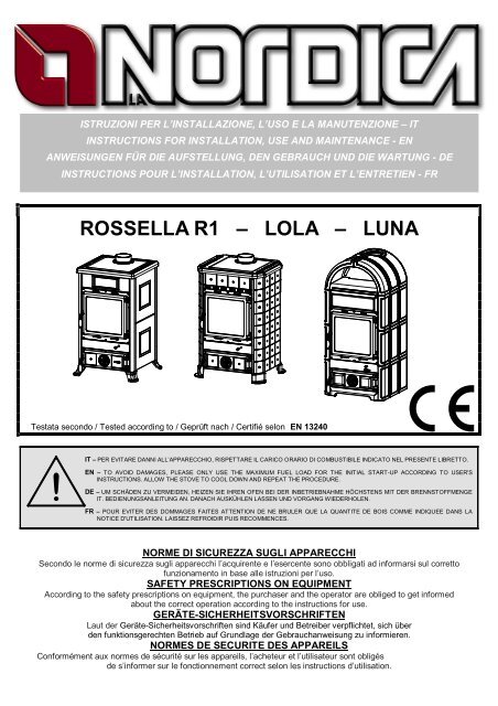
ISTRUZIONI PER L’INSTALLAZIONE, L’USO E LA MANUTENZIONE – IT<br />
INSTRUCTIONS FOR INSTALLATION, USE AND MAINTENANCE - EN<br />
ANWEISUNGEN FÜR DIE AUFSTELLUNG, DEN GEBRAUCH UND DIE WARTUNG - DE<br />
INSTRUCTIONS POUR L’INSTALLATION, L’UTILISATION ET L’ENTRETIEN - FR<br />
<strong>ROSSELLA</strong> <strong>R1</strong> – <strong>LOLA</strong> – <strong>LUNA</strong><br />
Testata secondo / Tested according to / Geprüft nach / Certifié selon EN 13240<br />
|<br />
IT – PER EVITARE DANNI ALL’APPARECCHIO, RISPETTARE IL CARICO ORARIO DI COMBUSTIBILE INDICATO NEL PRESENTE LIBRETTO.<br />
!<br />
EN – TO AVOID DAMAGES, PLEASE ONLY USE THE MAXIMUM FUEL LOAD FOR THE INITIAL START-UP ACCORDING TO USER'S<br />
INSTRUCTIONS. ALLOW THE STOVE TO COOL DOWN AND REPEAT THE PROCEDURE.<br />
DE – UM SCHÄDEN ZU VERMEIDEN, HEIZEN SIE IHREN OFEN BEI DER INBETRIEBNAHME HÖCHSTENS MIT DER BRENNSTOFFMENGE<br />
IT. BEDIENUNGSANLEITUNG AN. DANACH AUSKÜHLEN LASSEN UND VORGANG WIEDERHOLEN.<br />
FR – POUR EVITER DES DOMMAGES FAITES ATTENTION DE NE BRULER QUE LA QUANTITE DE BOIS COMME INDIQUEE DANS LA<br />
NOTICE D'UTILISATION. LAISSEZ REFROIDIR PUIS RECOMMENCES.<br />
NORME DI SICUREZZA SUGLI APPARECCHI<br />
Secondo le norme di sicurezza sugli apparecchi l’acquirente e l’esercente sono obbligati ad informarsi sul corretto<br />
funzionamento in base alle istruzioni per l’uso.<br />
SAFETY PRESCRIPTIONS ON EQUIPMENT<br />
According to the safety prescriptions on equipment, the purchaser and the operator are obliged to get informed<br />
about the correct operation according to the instructions for use.<br />
GERÄTE-SICHERHEITSVORSCHRIFTEN<br />
Laut der Geräte-Sicherheitsvorschriften sind Käufer und Betreiber verpflichtet, sich über<br />
den funktionsgerechten Betrieb auf Grundlage der Gebrauchanweisung zu informieren.<br />
NORMES DE SECURITE DES APPAREILS<br />
Conformément aux normes de sécurité sur les appareils, l’acheteur et l’utilisateur sont obligés<br />
de s’informer sur le fonctionnement correct selon les instructions d’utilisation.
<strong>ROSSELLA</strong> – <strong>LOLA</strong> – <strong>LUNA</strong><br />
DICHIARAZIONE DI CONFORMITA’ DEL COSTRUTTORE<br />
Oggetto: assenza di amianto e cadmio<br />
Si dichiara che tutti i nostri apparecchi vengono assemblati con materiali che non presentano parti di amianto o suoi<br />
derivati e che nel materiale d’apporto utilizzato per le saldature non è presente/utilizzato in nessuna forma il cadmio,<br />
<strong>com</strong>e previsto dalla norma di riferimento.<br />
Oggetto: Regolamento CE n. 1935/2004<br />
Si dichiara che in tutti gli apparecchi da noi prodotti, i materiali destinati a venire a contatto con i cibi sono adatti<br />
all’uso alimentari, in conformità al Regolamento CE in oggetto.<br />
DECLARATION OF CONFORMITY OF THE MANUFACTURER<br />
Object: Absence of asbestos and cadmium<br />
We declare that the materials used for the assembly of all our appliances are without asbestos parts or asbestos derivates and that in the<br />
material used for welding, cadmium is not present, as prescribed in relevant norm.<br />
Object: CE n. 1935/2004 regulation.<br />
We declare that in all products we produce, the materials which will get in touch with food are suitable for alimentary<br />
use, according to the a.m. CE regulation.<br />
KONFORMITÄTSERKLÄRUNG DES HERSTELLERS<br />
Betreff: Fehlen von Asbest und Kadmium<br />
Wir bestätigen, dass die verwendeten Materialen oder Teilen für die Herstellung der La Nordica Geräte ohne Asbest<br />
und Derivat sind und auch das Lot für das Schweißen immer ohne Kadmium ist.<br />
Betreff: Ordnung CE n. 1935/2004.Wir erklären in alleiniger Verantwortung, dass die Materialen der Teile, die für<br />
den Kontakt mit Lebensmitteln vorgesehen sind, für die Nahrungsbenutzung geeignet sind und der Richtlinien CE n.<br />
1935/2004 erfüllen<br />
DÉCLARATION DE CONFORMITÉ DU FABRICANT<br />
Objet: absence d'amiante et de cadmium<br />
Nous déclarons que tous nos produits sont assemblés avec des matériaux qui ne présentent pas de parties en<br />
amiante ou ses dérivés et que le matériel d'apport utilisé pour les soudures ne présente/utilise pas de cadmium, sous<br />
aucune forme, <strong>com</strong>me prévu par la norme de référence.<br />
Objet: Règlement CE n. 1935/2004. Nous déclarons que dans tous nos appareils, les matériaux destinés à entrer en<br />
contact avec les aliments sont aptes à l'usage alimentaire, conformément au Règlement CE en question<br />
2 1191015 – Rev.04 – IT – EN – DE – FR
<strong>ROSSELLA</strong> – <strong>LOLA</strong> – <strong>LUNA</strong><br />
INDICE<br />
IT<br />
1. DATI TECNICI ................................................................................................................................................... 5<br />
2. DESCRIZIONE TECNICA .................................................................................................................................. 6<br />
2.1. REGISTRO ARIA PRIMARIA (valvola girevole) ........................................................................................................... 6<br />
2.2. REGISTRO ARIA SECONDARIA ................................................................................................................................ 6<br />
3. NORME PER L’INSTALLAZIONE ...................................................................................................................... 6<br />
4. SICUREZZA ANTINCENDIO ............................................................................................................................. 7<br />
4.1. PRONTO INTERVENTO ............................................................................................................................................ 7<br />
5. CANNA FUMARIA ............................................................................................................................................. 8<br />
5.1. POSIZIONE DEL COMIGNOLO .................................................................................................................................. 8<br />
6. COLLEGAMENTO AL CAMINO ....................................................................................................................... 10<br />
7. AFFLUSSO D’ARIA NEL LUOGO D’INSTALLAZIONE DURANTE LA COMBUSTIONE ................................... 10<br />
8. COMBUSTIBILI AMMESSI / NON AMMESSI ................................................................................................... 10<br />
9. ACCENSIONE ................................................................................................................................................. 11<br />
10. FUNZIONAMENTO NORMALE .................................................................................................................... 12<br />
11. FUNZIONAMENTO NEI PERIODI DI TRANSIZIONE ................................................................................... 12<br />
12. SCALDAVIVANDE (dove presente – <strong>LUNA</strong>) ................................................................................................. 13<br />
13. MANUTENZIONE E CURA .......................................................................................................................... 13<br />
13.1. PULIZIA CANNA FUMARIA ...................................................................................................................................... 13<br />
13.2. PULIZIA VETRO ...................................................................................................................................................... 13<br />
13.3. PULIZIA CASSETTO CENERE................................................................................................................................. 13<br />
13.4. LE MAIOLICHE ........................................................................................................................................................ 13<br />
14. FERMO ESTIVO .......................................................................................................................................... 15<br />
15. COLLEGAMENTO ALLA CANNA FUMARIA DI UN CAMINETTO O FOCOLARE APERTO ......................... 15<br />
16. SCHEDA TECNICA / TECHNICAL DATA SHEETS / TECHNISCHE KARTE / FICHE TECHNIQUE ............. 51<br />
17. POSIZIONAMENTO DEI DEFLETTORI / POSITION OF DEFLECTORS / STELLUNG DER PRALLPLATTEN /<br />
POSITION DES DEFLECTEURS ............................................................................................................................. 52<br />
INDEX<br />
EN<br />
1. TECHNICAL DATA .......................................................................................................................................... 16<br />
2. TECHNICAL DESCRIPTION ............................................................................................................................ 16<br />
2.1. PRIMARY AIR CONTROL (movable valve) ............................................................................................................... 17<br />
2.2. SECONDARY AIR CONTROL .................................................................................................................................. 17<br />
3. RULES FOR INSTALLATION........................................................................................................................... 17<br />
4. FIRE SAFETY .................................................................................................................................................. 17<br />
4.1. FIRST-AID MEASURES ........................................................................................................................................... 18<br />
5. FLUE ............................................................................................................................................................... 18<br />
5.1. CHIMNEY CAP ........................................................................................................................................................ 19<br />
6. CONNECTION TO THE CHIMNEY .................................................................................................................. 20<br />
7. AIR ENTRANCE INTO THE INSTALLATION PLACE DURING COMBUSTION ................................................ 21<br />
8. ADMITTED/NOT ADMITTED FUEL ................................................................................................................. 21<br />
9. LIGHTING ........................................................................................................................................................ 22<br />
10. NORMAL OPERATION ................................................................................................................................ 23<br />
11. OPERATION DURING TRANSITION PERIODS........................................................................................... 23<br />
12. FOOD WARMER OPERATION (if present – <strong>LUNA</strong>) ..................................................................................... 23<br />
13. MAINTENANCE AND CARE ........................................................................................................................ 23<br />
13.1. CLEANING OF THE FLUE ....................................................................................................................................... 24<br />
13.2. CLEANING OF THE GLASS ..................................................................................................................................... 24<br />
13.3. CLEANING OF THE ASH-DRAWER ......................................................................................................................... 24<br />
13.4. MAJOLICAS............................................................................................................................................................. 24<br />
14. SUMMER STOP .......................................................................................................................................... 25<br />
15. CONNECTING A CHIMNEY OR OPEN FURNACE TO THE FLUE .............................................................. 26<br />
16. SCHEDA TECNICA / TECHNICAL DATA SHEETS / TECHNISCHE KARTE / FICHE TECHNIQUE ............. 51<br />
17. POSIZIONAMENTO DEI DEFLETTORI / POSITION OF DEFLECTORS / STELLUNG DER PRALLPLATTEN /<br />
POSITION DES DEFLECTEURS ............................................................................................................................. 52<br />
1191015 – Rev.04 – IT – EN – DE – FR 3
<strong>ROSSELLA</strong> – <strong>LOLA</strong> – <strong>LUNA</strong><br />
INHALTSÜBERSICHT<br />
DE<br />
1. TECHNISCHE ANGABEN................................................................................................................................ 27<br />
2. TECHNISCHE BESCHREIBUNG ..................................................................................................................... 28<br />
2.1. DER PRIMÄRLUFTSCHIEBER (drehebare Klapppe) ................................................................................................ 28<br />
2.2. DER SEKUNDÄRLUFTSCHIEBER ........................................................................................................................... 28<br />
3. INSTALLATIONSVORSCHRIFTEN .................................................................................................................. 28<br />
4. BRANDSCHUTZ .............................................................................................................................................. 29<br />
4.1. NOTFALLMASSNAHMEN ........................................................................................................................................ 29<br />
5. SCHORNSTEINROHR..................................................................................................................................... 30<br />
5.1. SCHORNSTEIN ....................................................................................................................................................... 30<br />
6. KAMINANSCHLUSS ........................................................................................................................................ 32<br />
7. LUFTZUSTROM IN DEN AUFSTELLRAUM BEI DER VERBRENNUNG .......................................................... 32<br />
8. ZULÄSSIGE / UNZULÄSSIGE BRENNSTOFFE .............................................................................................. 33<br />
9. ANZÜNDEN ..................................................................................................................................................... 34<br />
10. NORMALBETRIEB....................................................................................................................................... 34<br />
11. BETRIEB IN DER ÜBERGANGSZEIT .......................................................................................................... 35<br />
12. TELLERWÄRMERFACH (wenn anwesend – <strong>LUNA</strong>) .................................................................................... 35<br />
13. WARTUNG UND PFLEGE ........................................................................................................................... 35<br />
13.1. REINIGUNG DES SCHORNSTEINS ......................................................................................................................... 35<br />
13.2. REINIGUNG DES GLASES ...................................................................................................................................... 36<br />
13.3. REINIGUNG DES ASCHEKASTENS ........................................................................................................................ 36<br />
13.4. DIE KACHELN ......................................................................................................................................................... 36<br />
14. SOMMERPAUSE ......................................................................................................................................... 37<br />
15. ANSCHLUSS AN DEN RAUCHABZUG EINES OFFENEN KAMINS ............................................................ 37<br />
16. SCHEDA TECNICA / TECHNICAL DATA SHEETS / TECHNISCHE KARTE / FICHE TECHNIQUE ............. 51<br />
17. POSIZIONAMENTO DEI DEFLETTORI / POSITION OF DEFLECTORS / STELLUNG DER PRALLPLATTEN /<br />
POSITION DES DEFLECTEURS ............................................................................................................................. 52<br />
TABLE DES MATIERES<br />
FR<br />
1. DONNES TECHNIQUES ................................................................................................................................. 39<br />
2. DESCRIPTION TECHNIQUE ........................................................................................................................... 40<br />
2.1. REGULATEUR AIR PRIMAIRE (vanne pivotante) ..................................................................................................... 40<br />
2.2. REGULATEUR AIR SECONDAIRE .......................................................................................................................... 40<br />
3. NORMES POUR L’INSTALLATION ................................................................................................................. 40<br />
4. SECURITE ANTINCENDIE .............................................................................................................................. 41<br />
4.1. INTERVENTION EN CAS D’URGENCE .................................................................................................................... 41<br />
5. CONDUIT DE FUMEE ..................................................................................................................................... 42<br />
5.1. POSITION DU TERMINAL DU CONDUIT DE FUMEE ............................................................................................... 42<br />
6. RACCORDEMENT AU CONDUIT DE FUMEE ................................................................................................. 44<br />
7. AFFLUX DE L'AIR DANS LE LIEU D'INSTALLATION PENDANT LA COMBUSTION ....................................... 44<br />
8. COMBUSTIBLES ADMIS / NON ADMIS .......................................................................................................... 45<br />
9. ALLUMAGE ..................................................................................................................................................... 45<br />
10. FONCTIONNEMENT NORMAL .................................................................................................................... 46<br />
11. FONCTIONNEMENT PENDANT LES PERIODES DE TRANSITION ............................................................ 47<br />
12. CHAUFFE-PLATS (où présent – <strong>LUNA</strong>) ....................................................................................................... 47<br />
13. ENTRETIEN ET SOIN .................................................................................................................................. 47<br />
13.1. NETTOYAGE DU CONDUIT DE FUMEE .................................................................................................................. 47<br />
13.2. NETTOYAGE DE LA VITRE ..................................................................................................................................... 47<br />
13.3. NETTOYAGE DU CENDRIER .................................................................................................................................. 48<br />
13.4. LES FAIENCES LA NORDICA .................................................................................................................................. 48<br />
14. ARRET PENDANT L’ETE ............................................................................................................................ 49<br />
15. RACCORDEMENT AU CONDUIT DE FUMEE D’UNE CHEMINEE OU D’UN FOYER OUVERT .................. 49<br />
16. SCHEDA TECNICA / TECHNICAL DATA SHEETS / TECHNISCHE KARTE / FICHE TECHNIQUE ............. 51<br />
17. POSIZIONAMENTO DEI DEFLETTORI / POSITION OF DEFLECTORS / STELLUNG DER PRALLPLATTEN /<br />
POSITION DES DEFLECTEURS ............................................................................................................................. 52<br />
4 1191015 – Rev.04 – IT – EN – DE – FR
<strong>ROSSELLA</strong> – <strong>LOLA</strong> – <strong>LUNA</strong><br />
1. DATI TECNICI<br />
Definizione:<br />
Stufa a legna secondo EN 13240<br />
<strong>ROSSELLA</strong><br />
<strong>R1</strong><br />
<strong>LOLA</strong><br />
<strong>LUNA</strong><br />
Sistema costruttivo 1 1 1<br />
Potenza nominale in kW 8 8 8<br />
Rendimento in % 81.9 81.9 81.9<br />
Diametro tubo in mm 130 130 130<br />
Consumo orario legna in kg / h (legna con 20% umidità) 2.3 2.3 2.3<br />
Depressione a rendimento calorifico nominale in mmH 2 O – legna 1.2 1.2 1.2<br />
Emissione gas di scarico in g/s – legna 7.2 7.2 7.2<br />
CO misurato al 13% di ossigeno in % 0.1 0.1 0.1<br />
Temperatura gas di scarico nel mezzo in C° - legna 163 163 163<br />
Dimensioni apertura focolare in mm (L x H) 315 x 285 315 x 285 315 x 285<br />
Dimensioni corpo focolare / testata focolare in mm (L x H x P) 377x395x415 377x420x385 377x420x385<br />
Tipo di griglia<br />
Piana,girevole dall’esterno<br />
Altezza stufa in mm 915 920 1169<br />
Larghezza stufa in mm 578 623 540<br />
Profondità stufa (con maniglie) in mm 586 562 564<br />
Peso in Kg 156 160 193<br />
Distanze di sicurezza antincendio Capitolo 4<br />
Il volume di riscaldamento delle stufe secondo EN 13240, per edifici il cui isolamento termico non corrisponde alle<br />
disposizioni sulla protezione del calore, è:<br />
(30 Kcal/h x m 3 ) - tipo di costruzione favorevole: 230 m³<br />
(40 Kcal/h x m 3 ) - tipo di costruzione meno favorevole: 172 m³<br />
(50 Kcal/h x m 3 ) - tipo di costruzione sfavorevole: 138 m³<br />
Con un isolamento termico adeguato alle disposizioni sulla protezione del calore il volume di riscaldamento è<br />
maggiore.<br />
Con un riscaldamento temporaneo, in caso di interruzioni superiori a 8h, la capacità di riscaldamento diminuisce del<br />
25% circa.<br />
1191015 – Rev.04 – IT 5
<strong>ROSSELLA</strong> – <strong>LOLA</strong> – <strong>LUNA</strong><br />
2. DESCRIZIONE TECNICA<br />
Le stufe a legna La Nordica si addicono a riscaldare spazi abitativi per alcuni periodi, o a sostenere un riscaldamento<br />
centralizzato insufficiente. Esse sono ideali per appartamenti di vacanza e case del fine settimana oppure <strong>com</strong>e<br />
riscaldamento ausiliario durante tutto l’anno. Come <strong>com</strong>bustibili vengono utilizzati ceppi di legna.<br />
La stufa è costituita di lastre in lamiera d’acciaio zincata, ghisa smaltata e ceramica termo-radiante. Il focolare è<br />
internamente rivestito di singole lastre in ghisa, la parte posteriore è estraibile. Grazie a dei fori calibrati, praticati su<br />
quest’ultima, viene garantito un apporto di aria pre-riscaldata all’interno del focolare, ottenendo così una post<strong>com</strong>bustione<br />
che aumenta il rendimento e riduce le emissioni dei gas. Al suo interno si trova una griglia girevole<br />
estraibile. Il focolare è dotato di una porta panoramica con vetro ceramico (resistente fino a 700°C). Questo consente<br />
un’affascinante vista sulle fiamme ardenti. Inoltre viene così impedita ogni possibile fuoriuscita di scintille e fumo.<br />
Il riscaldamento dell’ambiente avviene:<br />
• per convezione (circa 70%): il passaggio dell’aria attraverso il doppio mantello della stufa rilascia calore<br />
nell’ambiente.<br />
• per irraggiamento (circa 30%): attraverso il vetro panoramico e le superfici esterne calde della stufa viene<br />
irraggiato calore nell’ambiente.<br />
La stufa è dotata di registri per l’aria primaria e secondaria, con i quali viene<br />
regolata la <strong>com</strong>bustione.<br />
Vedi paragrafo 10.<br />
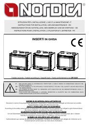
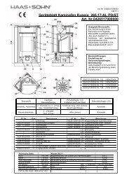
2.1. REGISTRO ARIA PRIMARIA (valvola girevole)<br />
Con il registro (valvola girevole) posto sotto la porta del focolare viene<br />
regolato il passaggio dell’aria primaria attraverso il cassetto cenere e la griglia<br />
in direzione del <strong>com</strong>bustibile (Figura 1 pos.A). L’aria primaria è necessaria<br />
per il processo di <strong>com</strong>bustione. Il cassetto cenere deve essere svuotato<br />
regolarmente, in modo che la cenere non possa ostacolare l’entrata dell’aria<br />
primaria per la <strong>com</strong>bustione. Attraverso l’aria primaria viene anche mantenuto<br />
vivo il fuoco.<br />
Durante la <strong>com</strong>bustione di legna, il registro dell’aria primaria deve essere<br />
aperto solo un poco, poiché altrimenti la legna arde velocemente e la stufa si<br />
può surriscaldare.<br />
C<br />
B<br />
2.2. REGISTRO ARIA SECONDARIA<br />
Nella parte inferiore (Figura 1 pos.B) e nella parte superiore (pos.C) della<br />
porta del focolare si trova il registro per l’aria secondaria. Questo registro<br />
deve essere aperto (quindi spostato verso destra) in particolar modo per la<br />
<strong>com</strong>bustione di legna.<br />
A<br />
Figura 1<br />
3. NORME PER L’INSTALLAZIONE<br />
La stufa è assemblata e pronta per l’allacciamento e deve essere collegata mediante un raccordo all’esistente canna<br />
fumaria della casa. Il raccordo deve essere possibilmente corto, rettilineo, orizzontale o posizionato leggermente in<br />
salita. I collegamenti devono essere a tenuta stagna. E’ obbligatorio rispettare norme nazionali ed europee,<br />
disposizioni locali o in materia di legislazione edilizia, nonché regolamentazioni antincendio. Pertanto vi<br />
consigliamo di informarvi preventivamente presso il Vs. capo spazzacamino distrettuale.<br />
Bisogna inoltre verificare il sufficiente afflusso d’aria necessario alla <strong>com</strong>bustione, a tale proposito è fondamentale<br />
prestare attenzione a finestre e porte con chiusura stagna (guarnizioni di tenuta).<br />
Non è consentito il collegamento di più apparecchi allo stesso camino. Il diametro dell’apertura della canna fumaria<br />
per il collegamento deve corrispondere per lo meno al diametro del tubo fumo.<br />
L’apertura dovrebbe essere dotata di una connessione a muro per la ricezione del tubo di scarico e di un rosone.<br />
Prima dell’installazione verificare se la portata della sottostruttura regge il peso del vostro apparecchio. In caso di<br />
portata insufficiente è necessario adottare opportune misure (ad es. piastra per la distribuzione del peso).<br />
La Nordica S.p.A. non è responsabile del prodotto modificato senza autorizzazione e tanto meno per l’uso di<br />
ricambi non originali.<br />
NON MODIFICARE IL FOCOLARE.<br />
6 1191015 – Rev.04 – IT
<strong>ROSSELLA</strong> – <strong>LOLA</strong> – <strong>LUNA</strong><br />
4. SICUREZZA ANTINCENDIO<br />
Nell’installazione della stufa devono essere osservate le seguenti misure di sicurezza:<br />
a) Al fine di assicurare un sufficiente isolamento termico, rispettare la distanza minima di sicurezza dal retro e da<br />
entrambi i lati da elementi costruttivi ed oggetti infiammabili e sensibili al calore (mobili, rivestimenti di legno,<br />
stoffe ecc.) (vedi Figura 2 - A). Tutte le distanze minime di sicurezza sono indicate sulla targhetta tecnica<br />
del prodotto e NON si deve scendere al di sotto dei valori indicati).<br />
b) davanti alla porta del focolare, nell’area di radiazione della stessa, non deve esserci alcun oggetto o materiale di<br />
costruzione infiammabile e sensibile al calore a meno di 100 cm di distanza. Tale distanza può essere ridotta a<br />
40 cm qualora venga installata una protezione, retroventilata e resistente al calore, davanti all’intero <strong>com</strong>ponente<br />
da proteggere.<br />
c) qualora il prodotto venga installato su un pavimento di materiale infiammabile, bisogna prevedere un sottofondo<br />
ignifugo. I pavimenti in materiale infiammabile, <strong>com</strong>e moquette, parquet o sughero etc., devono essere<br />
sostituiti da uno strato di materiale non infiammabile, ad esempio ceramica, pietra, vetro o acciaio etc.<br />
(dimensioni secondo l’ordinamento regionale). Il sottofondo deve sporgere dall’apparecchio lateralmente di 30cm<br />
e frontalmente di almeno 50 cm oltre all’apertura della porta di carico (vedi Figura 2 B).<br />
d) sopra al prodotto non devono essere presenti <strong>com</strong>ponenti infiammabili (es. mobili - pensili).<br />
La stufa deve funzionare esclusivamente con il cassetto cenere inserito. I residui solidi della <strong>com</strong>bustione (ceneri)<br />
devono essere raccolti in un contenitore ermetico e resistente al fuoco. La stufa non deve mai essere accesa in<br />
presenza di emissioni gassose o vapori (per esempio colla per linoleum, benzina ecc.). Non depositate materiali<br />
infiammabili nelle vicinanze della stufa.<br />
A<br />
B<br />
Figura 2<br />
Durante la <strong>com</strong>bustione viene sprigionata energia termica che <strong>com</strong>porta un marcato riscaldamento delle superfici,<br />
della porta e del vetro del focolare, delle maniglie delle porte o di <strong>com</strong>ando, del tubo fumi ed eventualmente della<br />
parte anteriore dell’apparecchio. Evitate il contatto con tali elementi senza un corrispondente abbigliamento protettivo<br />
o senza utensili accessori (guanti resistenti al calore, dispositivi di <strong>com</strong>ando).<br />
Fate in modo che i bambini siano consapevoli di questi pericoli e teneteli lontani dal focolare durante il suo<br />
funzionamento.<br />
Quando si utilizza un <strong>com</strong>bustibile errato o troppo umido si potrebbero formare dei depositi (creosoto) nella canna<br />
fumaria con possibile incendio della canna fumaria stessa<br />
4.1. PRONTO INTERVENTO<br />
Se si manifesta un incendio nel collegamento o nella canna fumaria :<br />
a) Chiudere la porta di caricamento e del cassetto cenere.<br />
b) Chiudere i registri dell’aria <strong>com</strong>burente<br />
c) Spegnere tramite l’uso di estintori ad anidride carbonica ( CO2 a polveri )<br />
d) Richiedere l’immediato intervento dei Vigili del Fuoco<br />
Non spegnere il fuoco con l’uso di getti d’acqua.<br />
Quando la canna fumaria smette di bruciare, farla verificare da uno specialista per individuare eventuali crepe o punti<br />
permeabili.<br />
1191015 – Rev.04 – IT 7
<strong>ROSSELLA</strong> – <strong>LOLA</strong> – <strong>LUNA</strong><br />
5. CANNA FUMARIA<br />
Requisiti fondamentali per un corretto funzionamento<br />
dell’apparecchio:<br />
• la sezione interna deve essere preferibilmente<br />
circolare;<br />
• essere termicamente isolata ed impermeabile e<br />
costruita con materiali idonei a resistere al calore, ai<br />
prodotti della <strong>com</strong>bustione ed alle eventuali condense;<br />
• essere priva di strozzature ed avere andamento<br />
verticale con deviazioni non superiori a 45°;<br />
• se già usata deve essere pulita;<br />
• rispettare i dati tecnici del manuale di istruzioni;<br />
(1) (2)<br />
(3)<br />
(4)<br />
A+1/2A<br />
Max.<br />
A+1/2A<br />
A<br />
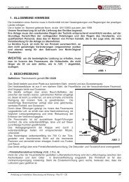
Qualora le canne fumarie fossero a sezione quadrata o<br />
rettangolare gli spigoli interni devono essere arrotondati con<br />
raggio non inferiore a 20 mm. Per la sezione rettangolare il<br />
rapporto massimo tra i lati deve essere ≤ 1,5.<br />
Una sezione troppo piccola provoca una diminuzione del<br />
tiraggio. Si consiglia un’altezza minima di 4 m.<br />
Sono vietate e pertanto pregiudicano il buon funzionamento<br />
dell’apparecchio: fibrocemento, acciaio zincato, superfici<br />
interne ruvide e porose. In Figura 3 sono riportati alcuni esempi<br />
di soluzione.<br />
La sezione minima deve essere di 4 dm 2 (per esempio<br />
20x20cm) per gli apparecchi il cui diametro di condotto è<br />
inferiore a 200mm, o 6,25dm 2 (per esempio 25x25cm) per<br />
gli apparecchi con diametro superiore a 200mm.<br />
(1) Canna fumaria in acciaio AISI 316 con doppia<br />
camera isolata con materiale resistente a<br />
400°C. Efficienza 100% ottima.<br />
(2) Canna fumaria in refrattario con doppia<br />
camera isolata e rivestimento esterno in<br />
calcestruzzo alleggerito. Efficienza 100%<br />
ottima.<br />
(3) Canna fumaria tradizionale in argilla sezione<br />
quadrata con intercapedini. Efficienza 80%<br />
ottima.<br />
(4) Evitare canne fumarie con sezione<br />
rettangolare interna il cui rapporto sia diverso<br />
Il tiraggio creato dalla vostra canna fumaria deve essere dal disegno. Efficienza 40% mediocre.<br />
Figura 3<br />
sufficiente ma non eccessivo.<br />
Una sezione della canna fumaria troppo importante può<br />
presentare un volume troppo grande da riscaldare e dunque provocare delle difficoltà di funzionamento<br />
dell’apparecchio; per evitare ciò provvedete ad intubare la stessa per tutta la sua altezza. Una sezione troppo piccola<br />
provoca una diminuzione del tiraggio.<br />
La canna fumaria deve essere adeguatamente distanziata da materiali infiammabili o <strong>com</strong>bustibili mediante<br />
un opportuno isolamento o un’intercapedine d’aria.<br />
E’ vietato far transitare all’interno della stessa tubazioni di impianti o canali di adduzione d’aria. E’ proibito inoltre<br />
praticare aperture mobili o fisse, sulla stessa, per il collegamento di ulteriori apparecchi diversi.<br />
5.1. POSIZIONE DEL COMIGNOLO<br />
Il tiraggio della canna fumaria dipende anche dall’idoneità del <strong>com</strong>ignolo.<br />
È pertanto indispensabile che, se costruito artigianalmente, la sezione di uscita sia più di due volte la sezione interna<br />
della canna fumaria.<br />
Dovendo sempre superare il colmo del tetto, il <strong>com</strong>ignolo dovrà assicurare lo scarico anche in presenza di vento<br />
(Figura 4).<br />
Il <strong>com</strong>ignolo deve rispondere ai seguenti requisiti:<br />
• avere sezione interna equivalente a quella del camino.<br />
• avere sezione utile d’uscita doppia di quella interna della canna fumaria.<br />
• essere costruito in modo da impedire la penetrazione nella canna fumaria di pioggia, neve e di qualsiasi<br />
corpo estraneo.<br />
• essere facilmente ispezionabile, per eventuali operazioni di manutenzione e pulizia.<br />
(1) Comignolo industriale<br />
ad elementi prefabbricati,<br />
consente un ottimo<br />
smaltimento dei fumi.<br />
(2) Comignolo artigianale.<br />
La giusta sezione di uscita<br />
deve essere minimo 2 volte<br />
la sezione interna della<br />
canna fumaria, ideale 2,5<br />
volte.<br />
(3) Comignolo per canna<br />
fumaria in acciaio con<br />
cono interno deflettore<br />
dei fumi.<br />
Figura 4<br />
8 1191015 – Rev.04 – IT
<strong>ROSSELLA</strong> – <strong>LOLA</strong> – <strong>LUNA</strong><br />
50 cm (1) In caso di canne fumarie affiancate un <strong>com</strong>ignolo dovrà<br />
sovrastare l’altro d’almeno 50 cm al fine d’evitare trasferimenti di<br />
pressione tra le canne stesse.<br />
Figura 5<br />
2 m 10 m<br />
1<br />
m<br />
(1) Il <strong>com</strong>ignolo non deve avere ostacoli entro i 10 m da muri,<br />
falde ed alberi. In caso contrario innalzare lo stesso d’almeno 1 m<br />
sopra l’ostacolo.<br />
Il <strong>com</strong>ignolo deve oltrepassare il colmo del tetto d’almeno 1 m.<br />
Figura 6<br />
> _ A<br />
>A<br />
0,5 m<br />
H min.<br />
(1)Asse colmo<br />
α<br />
(2)Tetto<br />
Figura 7<br />
COMIGNOLI DISTANZE E POSIZIONAMENTO UNI 10683/98<br />
Inclinazione del tetto<br />
Distanza tra il colmo e il<br />
camino<br />
Altezza minima del camino (misurata<br />
dallo sbocco)<br />
α A (m) H (m)<br />
15°<br />
30°<br />
45°<br />
60°<br />
< 1,85 m 0,50 m oltre il colmo<br />
> 1,85 m 1,00 m dal tetto<br />
< 1,50 m 0,50 m oltre il colmo<br />
> 1,50 m 1,30 m dal tetto<br />
< 1,30 m 0,50 m oltre il colmo<br />
> 1,30 m 2,00 m dal tetto<br />
< 1,20 m 0,50 m oltre il colmo<br />
> 1,20 m 2,60 m dal tetto<br />
1191015 – Rev.04 – IT 9
<strong>ROSSELLA</strong> – <strong>LOLA</strong> – <strong>LUNA</strong><br />
6. COLLEGAMENTO AL CAMINO<br />
Gli apparecchi con chiusura automatica della porta (tipo 1) devono obbligatoriamente funzionare, per motivi di<br />
sicurezza, con la porta del focolare chiusa (fatta eccezione per la fase di carico del <strong>com</strong>bustibile o l’eventuale<br />
rimozione della cenere).<br />
Gli apparecchi con le porte non a chiusura automatica (tipo 2) devono essere collegati ad una propria canna fumaria.<br />
Il funzionamento con porta aperta è consentito soltanto previa sorveglianza.<br />
La stufa è dotata di uno scarico fumi superiore.<br />
Il tubo di collegamento alla canna fumaria deve essere più corto possibile, rettilineo, a tenuta stagna e conforme alle<br />
normative vigenti.<br />
Il collegamento deve essere eseguito con tubi stabili e robusti (Vi consigliamo uno spessore di 2 mm) ed essere<br />
fissato ermeticamente alla canna fumaria. Il diametro interno del tubo di collegamento deve corrispondere al diametro<br />
esterno del tronchetto di scarico fumi della stufa DIN 1298.<br />
ATTENZIONE: qualora il collegamento attraversi particolari <strong>com</strong>posti da materiali infiammabili, nel raggio di 20cm<br />
attorno al tubo tutti i materiali infiammabili devono essere sostituiti da materiali ignifughi e resistenti al calore.<br />
Per un buon funzionamento dell’apparecchio è essenziale che nel luogo d’installazione venga immessa sufficiente<br />
aria per la <strong>com</strong>bustione (vedi paragrafo 7).<br />
La depressione al camino (TIRAGGIO) deve essere di almeno 12 Pascal (=1,2 mm di colonna d’acqua). La<br />
misurazione deve essere fatta sempre ad apparecchio caldo (resa calorifica nominale). Quando la depressione<br />
supera i 17 Pascal (1,7 mm di colonna d’acqua) è necessario ridurre la stessa con l’installazione di un regolatore di<br />
tiraggio supplementare (valvola a farfalla) sul tubo di scarico o nel camino.<br />
Per motivi di sicurezza la porta del focolare può essere aperta solo durante il caricamento di <strong>com</strong>bustibile. Il focolare<br />
deve rimanere chiuso durante il funzionamento ed i periodi di non-utilizzo.<br />
7. AFFLUSSO D’ARIA NEL LUOGO D’INSTALLAZIONE DURANTE LA COMBUSTIONE<br />
Poiché le stufe ricavano la loro aria di <strong>com</strong>bustione dal locale di installazione, è essenziale che nel luogo stesso<br />
venga immessa una sufficiente quantità d’aria. In caso di finestre e porte a tenuta stagna (es .case costruite con il<br />
criterio di risparmio energetico) è possibile che l’ingresso di aria fresca non venga più garantito e questo <strong>com</strong>promette<br />
il tiraggio dell’apparecchio, il vostro benessere e la vostra sicurezza. Bisogna pertanto garantire una alimentazione<br />
aggiuntiva di aria fresca mediante una presa d’aria esterna posta nelle vicinanze dell’apparecchio oppure tramite la<br />
posa di una conduttura per l’aria di <strong>com</strong>bustione che porti verso l’esterno od in un vicino locale areato, ad eccezione<br />
del locale caldaia o garage (VIETATO).<br />
Il tubo di collegamento deve essere liscio con un diametro minimo di 120 mm, deve avere una lunghezza massima di<br />
4 m e presentare non più di tre curve. Qualora questo sia collegato direttamente con l’esterno deve essere dotato di<br />
un apposito frangivento.<br />
L’entrata dell’aria per la <strong>com</strong>bustione nel luogo d’installazione non deve essere ostruita durante il funzionamento della<br />
stufa. E’ assolutamente necessario che negli ambienti, in cui vengono fatte funzionare stufe con un tiraggio naturale<br />
del camino, venga immessa tanta aria quanta ne è necessaria per la <strong>com</strong>bustione, ossia fino a 20 m³/ora. Il naturale<br />
ricircolo dell’aria deve essere garantito da alcune aperture fisse verso l’esterno, la loro grandezza è stabilita da<br />
relative normative in materia. Chiedete informazioni al Vostro spazzacamino di fiducia. Le aperture devono essere<br />
protette con delle griglie e non devono mai essere otturate.<br />
Le cappe di aspirazione, installate nel stesso locale dove è installata la stufa o nello stesso impianto di aria interna,<br />
possono influenzare negativamente il funzionamento della stufa (fino a provocare l’uscita di fumi nei locali<br />
dell’abitazione, nonostante la porta del focolare sia chiusa). Per tanto, le cappe di aspirazione non devono in nessun<br />
caso essere fatte funzionare contemporaneamente alla stufa.<br />
La depressione di una cappa aspirante può, nella peggiore delle ipotesi, trasformare la canna fumaria della<br />
stufa in presa d’aria esterna risucchiando i fumi nell’ambiente con conseguenze gravissime per le persone.<br />
8. COMBUSTIBILI AMMESSI / NON AMMESSI<br />
I <strong>com</strong>bustibili ammessi sono ceppi di legna da ardere. Si devono utilizzare esclusivamente ceppi di legna secca<br />
(contenuto d’acqua max 20%).<br />
I pezzi di legna dovrebbero avere una lunghezza di ca.30cm ed una circonferenza di 30cm max.<br />
La legna usata <strong>com</strong>e <strong>com</strong>bustibile deve avere un contenuto d’umidità inferiore al 20% e la si ottiene con un tempo di<br />
essiccazione di almeno un anno (legno tenero) o di due anni (legno duro) collocando tale legna in un luogo asciutto e<br />
10 1191015 – Rev.04 – IT
<strong>ROSSELLA</strong> – <strong>LOLA</strong> – <strong>LUNA</strong><br />
ventilato (per esempio sotto una tettoia). La legna umida rende l’accensione più difficile, perché è necessaria una<br />
maggiore quantità d’energia per far evaporare l’acqua presente.<br />
Il contenuto umido ha inoltre lo svantaggio che, con l’abbassarsi della temperatura, l’acqua si condensa prima nel<br />
focolare e quindi nel camino. La legna fresca contiene circa il 60% di H2O, perciò non è adatta ad essere bruciata.<br />
Tra gli altri non possono essere bruciati: resti di carbone, ritagli, cascami di corteccia e pannelli, legna umida<br />
o trattata con vernici, materiali di plastica; in tal caso decade la garanzia sull’apparecchio.<br />
Carta e cartone devono essere utilizzati solo per l’accensione. La <strong>com</strong>bustione di rifiuti è vietata e danneggerebbe<br />
la stufa e la canna fumaria, provocando inoltre danni alla salute, ed in virtù del disturbo olfattivo reclami da parte del<br />
vicinato.<br />
La legna non è un <strong>com</strong>bustibile a lunga durata e pertanto non è possibile un riscaldamento continuo della stufa<br />
durante la notte.<br />
IMPORTANTE: l’uso continuo e prolungato di legna particolarmente ricca di oli aromatici (p.e. Eucalipto, Mirto, etc.)<br />
provoca il deterioramento (sfaldamento) repentino dei <strong>com</strong>ponenti in ghisa che <strong>com</strong>pongono il prodotto.<br />
Specie<br />
Kg/mc<br />
KWh/Kg<br />
Umidità 20%<br />
Faggio 750 4,0<br />
Cerro 900 4,2<br />
Olmo 640 4,1<br />
Pioppo 470 4,1<br />
Larice * 660 4,4<br />
Abete rosso * 450 4,5<br />
Pino silvestre * 550 4,4<br />
* LEGNI RESINOSI POCO ADATTI PER UNA STUFA<br />
9. ACCENSIONE<br />
IMPORTANTE: alla prima accensione è inevitabile che venga prodotto un odore sgradevole (dovuto all’essiccamento<br />
dei collanti nella cordicella di guarnizione o delle vernici protettive), che sparisce dopo un breve utilizzo. Deve<br />
<strong>com</strong>unque essere assicurata una buona ventilazione dell’ambiente. Alla prima accensione Vi consigliamo di<br />
caricare una quantità ridotta di <strong>com</strong>bustibile e di aumentare lentamente la resa calorifica dell’apparecchio.<br />
Per effettuare una corretta prima accensione dei prodotti trattati con vernici per alte temperature, occorre sapere<br />
quanto segue:<br />
• i materiali di costruzione dei prodotti in questione non sono omogenei, infatti coesistono parti in ghisa, in<br />
acciaio, in refrattario e in maiolica;<br />
• la temperatura alla quale il corpo del prodotto è sottoposto non è omogenea: da zona a zona si registrano<br />
temperature variabili dai 300°C ai 500°C;<br />
• durante la sua vita, il prodotto è sottoposto a cicli alternati di accensioni e di spegnimento durante la stessa<br />
giornata e a cicli di intenso utilizzo o di assoluto riposo al variare delle stagioni;<br />
• la stufa nuova, prima di potersi definire stagionata, dovrà essere sottoposta a diversi cicli di avviamento per<br />
poter consentire a tutti i materiali ed alla vernice di <strong>com</strong>pletare le varie sollecitazioni elastiche;<br />
• in particolare inizialmente si potrà notare l’emissione di odori tipici dei metalli sottoposti a grande<br />
sollecitazione termica e di vernice ancora fresca. Tale vernice, sebbene in fase di costruzione venga cotta a<br />
250°C per qualche ora, dovrà superare più volte e p er una certa durata la temperatura di 350°C, prima di<br />
incorporarsi perfettamente con le superfici metalliche.<br />
Diventa quindi importante seguire questi piccoli accorgimenti in fase di accensione:<br />
1. Assicuratevi che sia garantito un forte ricambio d'aria nel luogo dove è installato l'apparecchio.<br />
2. Nelle prime accensioni, caricare non eccessivamente la camera di <strong>com</strong>bustione (circa metà della quantità<br />
indicata nel manuale d'istruzioni) e tenere il prodotto acceso per almeno 6-10 ore di continuo, con i registri<br />
meno aperti di quanto indicato nel manuale d'istruzioni.<br />
3. Ripetere questa operazione per almeno 4-5 o più volte, secondo la Vostra disponibilità.<br />
1191015 – Rev.04 – IT 11
<strong>ROSSELLA</strong> – <strong>LOLA</strong> – <strong>LUNA</strong><br />
4. Successivamente caricare sempre più (seguendo <strong>com</strong>unque quanto descritto sul libretto di istruzione<br />
relativamente al massimo carico) e tenere possibilmente lunghi i periodi di accensione evitando, almeno in<br />
questa fase iniziale, cicli di accensione-spegnimento di breve durata.<br />
5. Durante le prime accessioni nessun oggetto dovrebbe essere appoggiato sulla stufa ed in particolare sulle<br />
superfici laccate. Le superfici laccate non devono essere toccate durante il riscaldamento.<br />
6. Una volta superato il "rodaggio" si potrà utilizzare il Vostro prodotto <strong>com</strong>e il motore di un’auto, evitando<br />
bruschi riscaldamenti con eccessivi carichi.<br />
Per accendere il fuoco consigliamo di usare piccoli listelli di legno con carta oppure altri mezzi di accensione in<br />
<strong>com</strong>mercio, escluse tutte le sostanze liquide <strong>com</strong>e per es. alcool, benzina, petrolio e simili.<br />
Le aperture per l’aria (primaria e secondaria) devono essere aperte contemporaneamente solo un po' (si deve aprire<br />
anche l’eventuale valvola a farfalla posta sul tubo di scarico fumi). Quando la legna <strong>com</strong>incia ad ardere si può<br />
caricare altro <strong>com</strong>bustibile regolando l’aria per la <strong>com</strong>bustione secondo le indicazioni di cui al paragrafo 10.<br />
Mai sovraccaricare la stufa (confrontate la tabella tecnica – quantità max. di <strong>com</strong>bustibile caricabile).<br />
Troppo <strong>com</strong>bustibile e troppa aria per la <strong>com</strong>bustione possono causare surriscaldamento e quindi<br />
danneggiare la stufa.<br />
10. FUNZIONAMENTO NORMALE<br />
Gli apparecchi con chiusura automatica della porta (tipo 1) devono obbligatoriamente funzionare, per motivi di<br />
sicurezza, con la porta del focolare chiusa (fatta eccezione per la fase di carico del <strong>com</strong>bustibile o l’eventuale<br />
rimozione della cenere ).<br />
Gli apparecchi con le porte non a chiusura automatica (tipo 2) devono essere collegati ad una propria canna fumaria.<br />
Il funzionamento con porta aperta è consentito soltanto previa sorveglianza.<br />
IMPORTANTE: Per motivi di sicurezza la porta del focolare può essere aperta solo durante il caricamento di<br />
<strong>com</strong>bustibile. Il focolare deve rimanere chiuso durante il funzionamento ed i periodi di non-utilizzo.<br />
Il potere calorifico nominale della stufa è pari a 8 kW e viene raggiunto con un tiraggio (depressione) minimo di 12 Pa<br />
( = 1,2 mm di colonna d’acqua ).<br />
Con i registri posti sulla facciata della stufa viene regolata l’emissione di calore della stufa. Si devono aprire secondo<br />
il bisogno calorifico. La migliore <strong>com</strong>bustione (con emissioni minime) viene raggiunta quando, caricando legna, la<br />
maggior parte dell’aria per la <strong>com</strong>bustione passa attraverso il registro dell’aria secondaria.<br />
Non si deve mai sovraccaricare la stufa (vedi quantità max nella tabella sottostante).<br />
Troppo <strong>com</strong>bustibile e troppa aria per la <strong>com</strong>bustione possono causare surriscaldamento e quindi<br />
danneggiare la stufa . I danni causati da surriscaldamento non sono coperti da garanzia.<br />
Bisogna pertanto usare la stufa sempre con porta chiusa per evitare l’effetto forgia.<br />
Oltre che dalla regolazione dell’aria per la <strong>com</strong>bustione, l’intensità della <strong>com</strong>bustione e quindi la resa calorifica della<br />
Vostra stufa è influenzata dal camino. Un buon tiraggio del camino richiede una regolazione più ridotta dell’aria per la<br />
<strong>com</strong>bustione, mentre uno scarso tiraggio necessita maggiormente di un’esatta regolazione dell’aria per la<br />
<strong>com</strong>bustione.<br />
Per verificare la buona <strong>com</strong>bustione della stufa, controllate se il fumo che esce dal camino è trasparente. Se è bianco<br />
significa che la stufa non è regolata correttamente o la legna è troppo bagnata; se invece il fumo è grigio o nero è<br />
segno che la <strong>com</strong>bustione non è <strong>com</strong>pleta (è necessaria una maggior quantità di aria secondaria).<br />
COMBUSTIBILE<br />
Legna<br />
<strong>ROSSELLA</strong> <strong>LOLA</strong> <strong>LUNA</strong><br />
Aria primaria<br />
(valvola girevole)<br />
*5mm<br />
APERTO<br />
Aria<br />
secondaria<br />
5mm<br />
APERTO<br />
Aria primaria<br />
(valvola girevole)<br />
*5mm<br />
APERTO<br />
Aria<br />
secondaria<br />
5mm<br />
APERTO<br />
Aria primaria<br />
(valvola girevole)<br />
5mm<br />
APERTO<br />
Carica oraria 2.3 kg/h 2.3 kg/h 2.3 kg/h<br />
* girare la valvola affinché l’apertura misura 5 mm rispetto al cerchio esterno (= punto più ampio)<br />
Aria<br />
secondaria<br />
5mm<br />
APERTO<br />
11. FUNZIONAMENTO NEI PERIODI DI TRANSIZIONE<br />
Durante il periodo di transizione, ovvero quando le temperature esterne sono più elevate, in caso di improvviso<br />
aumento della temperatura si possono avere dei disturbi alla canna fumaria che fanno si che i gas <strong>com</strong>busti non<br />
vengono aspirati <strong>com</strong>pletamente. I gas di scarico non fuoriescono più <strong>com</strong>pletamente (odore intenso di gas).<br />
12 1191015 – Rev.04 – IT
<strong>ROSSELLA</strong> – <strong>LOLA</strong> – <strong>LUNA</strong><br />
In tal caso scuotete più frequentemente la griglia e aumentate l’aria per la <strong>com</strong>bustione. Caricate in seguito una<br />
quantità ridotta di <strong>com</strong>bustibile facendo sì che questo bruci più rapidamente (con sviluppo di fiamme) e si stabilizzi<br />
così il tiraggio della canna fumaria. Controllate quindi che tutte le aperture per la pulizia e i collegamenti al camino<br />
siano ermetici.<br />
12. SCALDAVIVANDE (dove presente – <strong>LUNA</strong>)<br />
Dopo aver pulito la griglia, caricate del <strong>com</strong>bustibile. Grazie all’apporto d’aria per la <strong>com</strong>bustione la temperatura dello<br />
scaldavivande può essere sensibilmente influenzata. Un sufficiente tiraggio al camino e dei canali ben puliti per il<br />
flusso dei fumi roventi attorno allo scaldavivande sono fondamentali.<br />
13. MANUTENZIONE E CURA<br />
Fate controllare dal Vostro spazzacamino responsabile di zona la regolare installazione della stufa, il collegamento al<br />
camino e l’aerazione.<br />
Per la pulizia delle parti smaltate usare acqua saponata o detergenti non abrasivi o chimicamente non aggressivi.<br />
IMPORTANTE : si possono usare esclusivamente parti di ricambio espressamente autorizzate ed offerte da La<br />
Nordica. In caso di bisogno Vi preghiamo di rivolgerVi al Vs rivenditore specializzato.<br />
L’ APPARECCHIO NON PUÒ ESSERE MODIFICATO!<br />
13.1. PULIZIA CANNA FUMARIA<br />
La corretta procedura di accensione, l’utilizzo di quantità e tipi di <strong>com</strong>bustibili idonei, il corretto posizionamento del<br />
registro dell’aria secondaria, il sufficiente tiraggio del camino e la presenza d’aria <strong>com</strong>burente sono indispensabili per<br />
il funzionamento ottimale dell’apparecchio. Almeno una volta l’anno è consigliabile eseguire una pulizia <strong>com</strong>pleta, o<br />
qualora sia necessario (problemi di malfunzionamento con scarsa resa). Questa operazione, fatta esclusivamente a<br />
stufa fredda, dovrebbe essere svolta da uno spazzacamino che contemporaneamente può effettuare un’ispezione.<br />
Durante la pulizia bisogna togliere dalla stufa il cassetto cenere ed il tubo fumi.<br />
Si può pulire il vano di raccolta fumi dal focolare e, dopo aver tolto il tubo fumi, anche dal tronchetto di scarico con<br />
l’aiuto di una spazzola e di un aspiratore.<br />
Fate attenzione che dopo la pulizia tutte le parti smontate vengano reinstallate in modo ermetico.<br />
13.2. PULIZIA VETRO<br />
Tramite uno specifico ingresso dell’aria secondaria la formazione di deposito di sporco, sul vetro della porta, viene<br />
efficacemente rallentata. Non può <strong>com</strong>unque mai essere evitata con l’utilizzo dei <strong>com</strong>bustibili solidi (es. legna umida )<br />
e questo non è da considerarsi <strong>com</strong>e un difetto dell’apparecchio .<br />
IMPORTANTE: la pulizia del vetro panoramico deve essere eseguita solo ed esclusivamente a stufa fredda<br />
per evitarne l’esplosione. Non usare <strong>com</strong>unque panni, prodotti abrasivi o chimicamente aggressivi.<br />
La corretta procedura di accensione, l’utilizzo di quantità e tipi di <strong>com</strong>bustibili idonei, il corretto posizionamento del<br />
registro dell’aria secondaria, il sufficiente tiraggio del camino e la presenza dell’aria <strong>com</strong>burente sono indispensabili<br />
per il funzionamento ottimale dell’apparecchio e per mantenere pulito il vetro.<br />
ROTTURA DEI VETRI: i vetri essendo in vetroceramica resistenti fino ad uno sbalzo termico di 750°C, no n<br />
sono soggetti a shock termici. La loro rottura può essere causata solo da shock meccanici (urti o chiusura<br />
violenta della porta ecc.). Pertanto la sostituzione non è in garanzia .<br />
13.3. PULIZIA CASSETTO CENERE<br />
Tutte le stufe a legna La Nordica hanno una griglia focolare ed un cassetto cenere per la<br />
raccolta delle ceneri (Figura 8 pos.A). Vi consigliamo di svuotare periodicamente il<br />
cassetto cenere e di evitarne il riempimento totale per non surriscaldare la griglia. Inoltre<br />
Vi consigliamo di lasciare sempre 3-4cm di cenere nel focolare.<br />
ATTENZIONE: le ceneri tolte dal focolare vanno riposte in un recipiente di materiale<br />
ignifugo dotato di un coperchio stagno. Il recipiente va posto su di un pavimento<br />
ignifugo, lontano da materiali infiammabili fino allo spegnimento e raffreddamento<br />
<strong>com</strong>pleto delle ceneri.<br />
A<br />
Figura 8<br />
13.4. LE MAIOLICHE<br />
Le maioliche La NORDICA sono prodotti di alta fattura artigianale e <strong>com</strong>e tali possono presentare micro-puntinature,<br />
cavillature ed imperfezioni cromatiche. Queste caratteristiche ne testimoniano la pregiata natura.<br />
1191015 – Rev.04 – IT 13
<strong>ROSSELLA</strong> – <strong>LOLA</strong> – <strong>LUNA</strong><br />
Smalto e maiolica, per il loro diverso coefficiente di dilatazione, producono microscrepolature (cavillatura) che ne<br />
dimostrano l’effettiva autenticità.<br />
Per la pulizia delle maioliche si consiglia di usare un panno morbido ed asciutto; se si usa un qualsiasi detergente o<br />
liquido, quest’ultimo potrebbe penetrare all’interno dei cavilli evidenziando gli stessi.<br />
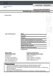
ISTRUZIONI PER IL MONTAGGIO DELLE PIASTRELLE <strong>LUNA</strong> – Figura 9<br />
1- Togliere le quattro viti (A) poste sulla parte superiore della stufa sotto il cappello in ghisa.<br />
2- Posizionare la cupola in metallo (B) in corrispondenza dei quattro fori e fissarla con le viti (A)<br />
precedentemente tolte.<br />
3- Fissare, con le viti in dotazione, il semicerchio posteriore (M) in corrispondenza dei due fori posti sulla schiena<br />
dell’apparecchio.<br />
4- Posizionare la piastrella inferiore (C).<br />
5- Agganciare la piastrella superiore (D) sui supporti (E).<br />
6- Inserire tre piastrelle laterali (F) in un lato, iniziando dal basso e agganciando i supporti (G) in corrispondenza<br />
dei sostegni laterali (I).Per questa operazione non utilizzare gli agganci (N).<br />
7- Ripetere l’operazione precedente sul lato opposto della stufa.<br />
8- Posizionare la piastrella piana (O) sugli appositi supporti del cappello in ghisa.<br />
9- Posizionare le due piastrelle curve (L) ed (I) sopra la cupola in metallo (B), agganciandole ai supporti <strong>com</strong>e<br />
mostrato nel particolare.<br />
10- Avvitare le due viti (P) nelle apposite sedi poste sulle piastrelle curve (non fissare troppo).<br />
AVVERTENZE<br />
- Togliere il nastro adesivo (H) prima di procedere con il montaggio delle piastrelle laterali.<br />
- Agganciare le piastrelle usando molta cura in quanto, essendo fragili, si possono danneggiare.<br />
<strong>LUNA</strong><br />
Figura 9<br />
14 1191015 – Rev.04 – IT
<strong>ROSSELLA</strong> – <strong>LOLA</strong> – <strong>LUNA</strong><br />
14. FERMO ESTIVO<br />
Dopo aver effettuato la pulizia del focolare, del camino e della canna fumaria, provvedendo all’eliminazione totale<br />
della cenere ed altri eventuali residui, chiudere tutte le porte del focolare ed i relativi registri e sconnettere<br />
l’apparecchio dal camino.<br />
Consigliamo di effettuare l’operazione di pulizia della canna fumaria almeno una volta all’anno; verificare nel<br />
frattempo l’effettivo stato delle guarnizioni che, se non perfettamente integre, non garantiscono il buon funzionamento<br />
dell’apparecchio!<br />
In tal caso è necessaria la sostituzione delle stesse.<br />
In caso di umidità del locale dove è posto l’apparecchio, sistemare dei sali assorbenti all’interno del focolare.<br />
Proteggere le parti in ghisa grezze, se si vuole mantenere inalterato nel tempo l’aspetto estetico, con della vaselina<br />
neutra.<br />
15. COLLEGAMENTO ALLA CANNA FUMARIA DI UN CAMINETTO O FOCOLARE APERTO<br />
Il canale fumi è il tratto di tubo che collega il prodotto alla canna fumaria, nel collegamento devono essere rispettati<br />
questi semplici ma importantissimi principi:<br />
• per nessuna ragione si dovrà usare il canale fumo avente un diametro inferiore a quello del collarino di uscita<br />
di cui è dotato il prodotto;<br />
• ogni metro di percorso orizzontale del canale fumo provoca una sensibile perdita di carico che dovrà<br />
eventualmente essere <strong>com</strong>pensata con un innalzamento della canna fumaria;<br />
• il tratto orizzontale non dovrà <strong>com</strong>unque mai superare i 2m (UNI 10683-2005);<br />
• ogni curva del canale fumi riduce sensibilmente il tiraggio della canna fumaria che dovrà essere<br />
eventualmente <strong>com</strong>pensata innalzandola adeguatamente;<br />
• la Normativa UNI 10683-2005 – ITALIA prevede che le curve o variazioni di direzione non devono in nessun<br />
caso essere superiori a 2 <strong>com</strong>presa l’immissione in canna fumaria.<br />
Volendo usare la canna<br />
fumaria di un caminetto o<br />
focolare aperto, sarà<br />
necessario chiudere<br />
ermeticamente la cappa al<br />
di sotto del punto di<br />
imbocco del canale fumo<br />
pos.A Figura 10.<br />
Se poi la canna fumaria è<br />
troppo grande (p.e. cm<br />
30x40 oppure 40x50) è<br />
necessario intubarla con<br />
un tubo di acciaio inox di<br />
almeno 200mm di<br />
diametro, pos.B, avendo<br />
cura di chiudere bene lo<br />
spazio rimanente fra il<br />
tubo stesso e la canna<br />
fumaria immediatamente<br />
sotto al <strong>com</strong>ignolo pos. C.<br />
C - Tamponamento<br />
B<br />
A - Chiusura ermetica<br />
Sportello di<br />
ispezione<br />
Figura 10<br />
Per ulteriori informazioni Vi preghiamo cortesemente di rivolgerVi al Vostro rivenditore di fiducia<br />
1191015 – Rev.04 – IT 15
<strong>ROSSELLA</strong> – <strong>LOLA</strong> – <strong>LUNA</strong><br />
1. TECHNICAL DATA<br />
Description :<br />
Stove tested according to EN 13240<br />
<strong>ROSSELLA</strong><br />
<strong>R1</strong><br />
<strong>LOLA</strong><br />
<strong>LUNA</strong><br />
Constructive system 1 1 1<br />
Rating power in kW 8 8 8<br />
Efficiency in % 81.9 81.9 81.9<br />
Pipe diameter in mm 130 130 130<br />
Hourly wood consumption in kg / h (wood with 20% humidity) 2.3 2.3 2.3<br />
Depression by rating calorific value in mmH 2 O wood 1.2 1.2 1.2<br />
Emission of exhaust gases in g/s- wood 7.2 7.2 7.2<br />
Mean content of CO to 13% O 2 in % 0.1 0.1 0.1<br />
Temperature of exhaust gases in °C - wood 163 163 163<br />
Size of hearth opening in mm (W x H) 315 x 285 315 x 285 315 x 285<br />
Hearth body size /Hearth head in mm (W x H x D) 377x395x415 377x420x385 377x420x385<br />
Grate type<br />
Flat grate, from outside movable<br />
Stove height in mm 915 920 1169<br />
Stove width in mm 578 623 540<br />
Stove depth in mm 586 562 564<br />
Weight in Kg 156 160 193<br />
Safety measures Chapter 4<br />
The heating volume of the stoves according to EN 13240, for those buildings in which the thermal insulation does not<br />
correspond to the instructions on heat protection is:<br />
(30 Kcal/h x m 3 ) - type of favourable construction: 230 m³<br />
(40 Kcal/h x m 3 ) - type of less favourable construction: 172 m³<br />
(50 Kcal/h x m 3 ) - type of unfavourable construction: 138 m³<br />
With a suitable thermal insulation, corresponding to the provisions on heat protection, the heating volume is greater.<br />
In case of a temporary heating, with interruptions of more than 8 hours, the heating volume decreases of about 25%.<br />
2. TECHNICAL DESCRIPTION<br />
The chimney stoves of La Nordica are suitable to heat living spaces for some periods or to support an insufficient<br />
centralized heating system. They are ideal for holiday apartments and weekend houses or as an auxiliary heating<br />
system during the whole year. As fuel, it is possible to use wood logs.<br />
The stove is made of sheets in galvanized steel, enamelled cast iron and thermo radiant ceramic.<br />
16 1191015 – Rev.04 – EN
<strong>ROSSELLA</strong> – <strong>LOLA</strong> – <strong>LUNA</strong><br />
The hearth is internally sheathed with single sheets in cast iron and inside it there is a turning and extractable grate;<br />
the back side is extractable. Thanks to some calibrated holes made over that side, the supply of pre-heated air inside<br />
hearth is guaranteed and having, in this way, a post-<strong>com</strong>bustion which increases theyield and reduces gas output.<br />
Inside it there is a turning and extractable grate. The hearth is equipped with a panoramic door with ceramic glass<br />
(resistant up to 700 °C) This allows a wonderful vi ew on the burning flames and avoids any possible output of sparks<br />
and smoke.<br />
The heating of the environment is made by:<br />
• Convection: (70%) the air passage through the double mantel of the stove releases heat into the<br />
environment;<br />
• Irradiation (30%): through the panoramic glass and the external hot surfaces of the stove, the heat is<br />
radiated into the environment.<br />
The stove is equipped with controls of primary and secondary air by which it<br />
is adjusted the <strong>com</strong>bustion air.<br />
(see chapter 10).<br />
C<br />
2.1. PRIMARY AIR CONTROL (movable valve)<br />
With the primary air control (movable valve), which is found below the hearth<br />
door it is adjusted the passage of air through the ash drawer and the grate in<br />
the fuel direction (Picture 1 pos.A). The primary air is necessary for the<br />
<strong>com</strong>bustion process. The ash drawer must be regularly emptied, so that the<br />
ash does not obstruct the primary air entry. Through the primary air the fire is<br />
also kept alive.<br />
During wood <strong>com</strong>bustion, the register of primary air must be opened only for<br />
a while, because otherwise the wood burns fast and the stove may overheat.<br />
B<br />
2.2. SECONDARY AIR CONTROL<br />
On the inferior part (Picture 1 pos. B) and on the over part (pos. C) of the<br />
door there is the secondary air control. Also this register must be opened<br />
(then moved to the right), especially for wood <strong>com</strong>bustion.<br />
A<br />
Picture 1<br />
3. RULES FOR INSTALLATION<br />
The stove, assembled and ready for the installation, must be connected with a junction to the existing flue of the<br />
house. The junction must be possibly short, straight, horizontal or positioned a little uphill. The connections must be<br />
tight.<br />
It is obligatory to respect the National and European rules, local regulations concerning building matter and<br />
also fireproofs rules. Please apply to your chimney sweeper for all information.<br />
You should verify the sufficient air entrance for the <strong>com</strong>bustion in the installation place, with particular attention to<br />
windows and doors with tight closing (seal ropes).<br />
It is not allowed the connection of various appliances to the same chimney. The diameter of the opening for the<br />
connection must correspond at least to the diameter of the smokes pipe. The opening should be equipped with a wall<br />
connection for the reception of the exhaust pipe and a rose window.<br />
Before installation, verify if your floor can support the weight of the stove (for ex. distributing weight plate).<br />
LA NORDICA is not responsible in case of modification of the product and for the use of not original spare<br />
parts.<br />
THE HEARTHS MUST NOT BE MODIFIED.<br />
4. FIRE SAFETY<br />
In the installation of the stove the following safety measures are to be followed:<br />
a) In order to ensure sufficient thermal insulation, respect the minimum safety distance from objects or furnishing<br />
<strong>com</strong>ponents flammable and sensitive to heat (furniture, wood sheathings, fabrics. etc.) and from materials with<br />
flammable structure (see Picture 2 - A). All the minimum safety distances are shown on the product data<br />
plate and lower values must not be used.<br />
b) in front of the chimney stove there must not be any flammable object or building material, sensitive to heat, at less<br />
100 cm’s. of distance. This distance can be reduced to 40 cm’s if you will install in front of the element to protect<br />
a retro ventilated and heat resistant protection.<br />
c) If the product is installed on a non totally refractory floor, one must foresee a fireproof background. The floors<br />
made of inflammable material, such as moquette, parquet or cork etc., must be replaced by a layer of no-<br />
1191015 – Rev.04 – EN 17
<strong>ROSSELLA</strong> – <strong>LOLA</strong> – <strong>LUNA</strong><br />
inflammable material, for instance ceramic, stone, glass or steel etc. (dimensions according to the local<br />
regulations). The platform must stick out 30 cm’s sideways and 50 cm’s on the front side over the loading door<br />
(Picture 2 B)<br />
d) no flammable <strong>com</strong>ponents (e.g. wall units) must be present above the product.<br />
The chimney stove must operate exclusively with the ash drawer inserted. The solid residue of the <strong>com</strong>bustion<br />
(ashes) must be collected in a hermetic container, resistant to fire. The stove must never be ignited when there are<br />
gas or steam emissions (e.g. glue for linoleum, gasoline, etc.). Never deposit flammable materials near the stove.<br />
During the <strong>com</strong>bustion will be spread thermal energy which warms up the surfaces, the door, the fireplace glass, the<br />
handles and knobs, the smoke pipe and the front side of the stove. Please avoid the contact of these parts without<br />
gloves or the relevant tools.<br />
Warn children of the danger and keep them away during the operation of the stove.<br />
The use of a wrong or wet fuel causes the formation of creosote deposits in the flue and will fuel a chimney fire.<br />
A<br />
B<br />
Picture 2<br />
4.1. FIRST-AID MEASURES<br />
Should any fire arise in the stack or in the flue:<br />
a) Close the feeding door and the ash drawer door;<br />
b) Close the controls of <strong>com</strong>bustion air;<br />
c) Extinguish the fire using carbon dioxide fire-fighting means (CO 2 dust);<br />
d) Seek immediate intervention of FIRE BRIGADE.<br />
DO NOT EXTINGUISH FIRE USING WATER JETS.<br />
When the fire has been extinguished, let the flue check by an expert to find possible cracks and permeable points.<br />
5. FLUE<br />
Essential requirements for a correct operation of the appliance:<br />
• the internal section must be preferably circular;<br />
• be thermally insulated and water-proof and produced with materials suitable to resist to heat, <strong>com</strong>bustion<br />
products and possible condensates;<br />
• not be throttled and show a vertical arrangement with deviations not greater than 45°;<br />
• if already used, it must be clean;<br />
• observe the technical data of the instructions manual;<br />
Should the flues have a square or rectangular section, internal edges must be rounded with a radius not lower than 20<br />
mm. For the rectangular section, the maximum ratio between the sides must be ≤ 1.5.<br />
18 1191015 – Rev.04 – EN
<strong>ROSSELLA</strong> – <strong>LOLA</strong> – <strong>LUNA</strong><br />
A too small section causes a decrease of the draught. It is<br />
suggested a minimum height of 4 m.<br />
(1) (2)<br />
The following features are forbidden and therefore they endanger<br />
the good operation of the appliance: asbestos cement,<br />
galvanized steel, rough and porous internal surfaces. Picture 3<br />
gives some examples of execution.<br />
The minimum section must be 4 dm 2 (for example 20 x 20<br />
cm’s) for appliances whose duct diameter is lower than 200<br />
mm, or 6.25 dm 2 (for example 25 x 25 cm’s) for appliances<br />
with diameter greater than 200 mm.<br />
(3)<br />
(4)<br />
A+1/2A<br />
Max.<br />
A+1/2A<br />
A<br />
The draught created by the flue must be sufficient, but not<br />
excessive.<br />
A too big flue section can feature a too big volume to be heated<br />
and consequently cause difficulties in the operation of the<br />
appliance; to avoid this, tube the flue along its whole height. A too<br />
small section causes a decrease of the draught.<br />
The flue must be properly spaced from any flammable<br />
materials or fuels through a proper insulation or an air<br />
cavity.<br />
It is forbidden to let plant piping or air feeding channels pass in<br />
the same flue. Moreover, it is forbidden to create movable or fixed<br />
openings on the same for the connection of further other<br />
appliances.<br />
(1) AISI 316 steel flue with double chamber<br />
insulated with material resistant to 400°C.<br />
Efficiency 100% excellent.<br />
(2) Refractory flue with double insulated chamber<br />
and external coating in lightweight concrete.<br />
Efficiency 100% excellent.<br />
(3) Traditional clay flue square section with<br />
cavities. Efficiency 80% excellent.<br />
(4) Avoid flues with rectangular internal section<br />
whose ratio differs from the drawing. Efficiency<br />
40% poor.<br />
Picture 3<br />
5.1. CHIMNEY CAP<br />
The draught of the flue depends also on the suitability of the chimney cap.<br />
Therefore, if it is handicraft constructed, the output section must be more than twice as big as the internal section of<br />
the flue.<br />
Should it be necessary to exceed the ridge of the roof, the chimney cap must assure the discharge also in case of<br />
windy weather (Picture 4).<br />
The chimney cap must meet the following requirements:<br />
• have internal section equivalent to that of the stack.<br />
• have a useful output section twice as big as the flue internal one.<br />
• be manufactured in such a way as to prevent the penetration of rain, snow, and any other foreign body in the flue.<br />
• be easily checkable, for any possible maintenance and cleaning operation.<br />
(1) Industrial chimney cap<br />
with pre-fabricated<br />
elements – it allows an<br />
excellent discharge of the<br />
smokes.<br />
(2) Handicraft chimney cap.<br />
The right output section must<br />
be at least twice as big as the<br />
internal section of the flue<br />
(ideal value: 2.5 times).<br />
(3) Chimney cap for steel<br />
flue with conical deflector<br />
of smokes.<br />
Picture 4<br />
50 cm<br />
(1) In case of flues side by side, a chimney cap must be higher<br />
than the other one of at least 50 cm in order to avoid pressure<br />
transfers between the flues themselves.<br />
Picture 5<br />
1191015 – Rev.04 – EN 19
<strong>ROSSELLA</strong> – <strong>LOLA</strong> – <strong>LUNA</strong><br />
2 m 10 m<br />
1<br />
m<br />
(1) The chimney cap must not show hindrances within 10 m from<br />
walls, pitches and trees. Otherwise raise it of at least 1 m over the<br />
hindrance.<br />
The chimney cap must exceed the ridge of the roof of at least 1 m.<br />
Picture 6<br />
> _ A<br />
>A<br />
0,5 m<br />
H min.<br />
(1)Ridge axis<br />
α<br />
(2)Roof<br />
Picture 7<br />
CHIMNEY CAPS - DISTANCES AND POSITIONING UNI 10683/98<br />
Inclination of the<br />
roof<br />
Distance between the roof<br />
ridge and the stack<br />
Minimum height of the stack<br />
(measured from the outlet)<br />
α A (m) H (m)<br />
15°<br />
30°<br />
45°<br />
60°<br />
< 1.85 m 0.50 m above the roof ridge<br />
> 1.85 m 1.00 m from the roof<br />
< 1.50 m 0.50 m above the roof ridge<br />
> 1.50 m 1.30 m from the roof<br />
< 1.30 m 0.50 m above the roof ridge<br />
> 1.30 m 2.00 m from the roof<br />
< 1.20 m 0.50 m above the roof ridge<br />
> 1.20 m 2.60 m from the roof<br />
6. CONNECTION TO THE CHIMNEY<br />
For safety reasons the door of the appliances with constructive system 1, must be opened only for the loading of the<br />
fuel or for removing the ashes, while during the operation and the rest, the door of the hearth must remain closed.<br />
The appliances with constructive system 2 must be connected to their own flue. The operating with open door is<br />
allowed under supervision.<br />
20 1191015 – Rev.04 – EN
<strong>ROSSELLA</strong> – <strong>LOLA</strong> – <strong>LUNA</strong><br />
The stove is endowed with an upper exhaust pipe. The connection pipe to the flue must be the shortest possible,<br />
right, tight and according to the current regulations.<br />
The connection to the chimney must be performed with stable and strong pipes (we re<strong>com</strong>mend a thickness of 2<br />
mm). The pipe for smokes exhaust must be fixed hermetically to the chimney. The diameter inside the connection<br />
pipe must correspond to the external diameter of the smokes exhaust small trunk of the stove. This is ensured by<br />
pipes according to DIN 1298.<br />
ATTENTION: Eventual flammable pieces in the area of 20 cm’s round the connection pipes must be changed with<br />
fireproof and not sensitive to heat materials.<br />
For a good operation of the equipment it is essential that in the installation place it is introduced sufficient air for<br />
<strong>com</strong>bustion (see chapter 7).<br />
The depression on the chimney should be 12 Pascal (=1.2 mm of water column). The measurement must be done<br />
always with the equipment hot (rating calorific value). When the depression exceeds 17 PA (1.7mm of water column)<br />
it is necessary to reduce the same with the installation of an additional flue adjuster (butterfly valve) on the exhaust<br />
pipe or in the chimney.<br />
For safety reasons the door of the stove must be opened only for the loading of the fuel or for removing the ashes,<br />
while during the operation and the rest, the door of the hearth must remain closed.<br />
7. AIR ENTRANCE INTO THE INSTALLATION PLACE DURING COMBUSTION<br />
As the stoves take their <strong>com</strong>bustion air from the installation place, it is essential that a sufficient quantity of air is<br />
introduced in the installation room itself.<br />
In case of tight doors and windows (for example houses built according to the energy saving criteria) it is possible that<br />
the air entrance is not guaranteed, <strong>com</strong>promising the draught, the welfare and the security of the people. It is<br />
necessary to guarantee a further air entrance through an external air intake, to be positioned in the nearby of the<br />
appliance or through air connection towards outside or a near ventilated room, with the exception of thermal units<br />
place or garages (FORBIDDEN).<br />
The connection pipe must be flat with a minimum diameter of 120 mm, a maximum length of 4 m and with no more<br />
than 3 bends. If there is a direct connection with the outside it must be endowed with a special windbreak.<br />
The air entrance for <strong>com</strong>bustion into the installation place must not be closed during the operation of the stove. It is<br />
absolutely necessary that in the environment in which the stoves operate with the natural flue of the chimney, it is<br />
introduced as much air as necessary for the <strong>com</strong>bustion, i.e. up to 20 m 3 /hour.<br />
The natural recirculation of air must be ensured by some fixed openings on the outside. The size of the necessary<br />
openings for air is fixed by the relevant prescriptions. Ask information to your chimney sweeper. The openings should<br />
be protected with grids and should never be obstructed.<br />
An extraction hood (aspirating) installed in the same room or in a room nearby, in case of insufficient flow of fresh air<br />
may negatively affect the functions of your appliance with the output of <strong>com</strong>busted gasses (smoke, smell even if with<br />
the door closed). As consequence the extraction hoods must not absolutely work at the same time with the stove.<br />
The depression in an extraction hood can at worst hypothesis, transforms the flue into an external air intake,<br />
by sucking the smokes of the rooms with dangerous consequences for the people.<br />
8. ADMITTED/NOT ADMITTED FUEL<br />
The fuel admitted is made of wood logs. One must use only logs of dry wood (water content max. 20 %). The wood<br />
pieces should have a length of 30 cm’s and a maximum circumference of 30 cm’s.<br />
The wood used as fuel must have a moisture contents lower than 20%, which is obtained after at least 1 year drying<br />
(tender wood) or 2 years (hard wood) and must be stored in a dry and ventilated place (for ex. under a shed). The wet<br />
wood makes ignition more difficult because it is necessary a greater quantity of energy to evaporate the existing<br />
water. The humid contents has the disadvantage that, with the temperature lowering, the water condensates first in<br />
the hearth and then in the chimney. The unseasoned wood contains about 60 % of H20, and then it is not suitable to<br />
be burnt.<br />
Among the others, the following cannot be burnt: remainders of coal, cut-outs, scraps of bark and panels,<br />
humid wood or treated with varnishes, plastic materials; in this case the warranty on the equipment expires.<br />
Paper and carton must be used only for ignition.<br />
The <strong>com</strong>bustion of wastes is forbidden and may damage the stove and the chimney, causing health damages and<br />
claims by the neighbourhood owing to the bad smell.<br />
The wood is not a fuel, which allows a continuous operation of the appliance, as consequence the heating all over the<br />
night is not possible.<br />
1191015 – Rev.04 – EN 21
<strong>ROSSELLA</strong> – <strong>LOLA</strong> – <strong>LUNA</strong><br />
Variety<br />
Kg/mc<br />
KWh/Kg<br />
moistness 20%<br />
Beech 750 4,0<br />
Oak 900 4,2<br />
Elm 640 4,1<br />
Poplar 470 4,1<br />
Larch* 660 4,4<br />
Spruce* 450 4,5<br />
Scots pine * 550 4,4<br />
* Resinous wood not suitable for the burning<br />
ATTENTION : the continuous and protracted use of aromatic wood (eucalyptus, myrtle etc.) quickly damages the<br />
cast iron parts (cleavage) of the product.<br />
9. LIGHTING<br />
IMPORTANT: The first time that the appliance is lit, there will be an odour given off (due to the drying of the<br />
adhesives of the junction chord), which disappears after a short use. It must be ensured, in any case, a good<br />
ventilation of the environment. Upon the first ignition we suggest loading a reduced quantity of fuel and slightly<br />
increasing the calorific value of the equipment.<br />
To perform a correct first lighting of the products treated with paints for high temperature, it is necessary to know the<br />
following information:<br />
• the construction materials of the involved products are not homogeneous, as matter of fact there are<br />
simultaneously parts in cast iron, refractory, majolica and steel;<br />
• the temperature to which the body of the product is subject is not homogeneous: from area to area, variable<br />
temperatures within the range of 300°C - 500 °C are detected.<br />
• during its life, the product is subject to alternated lighting and extinguishing cycles in the same day, as well as<br />
to cycles of intense use or of absolute standstill when season changes;<br />
• the new appliance, before being considered seasoned has to be subject to many start cycles to allow all<br />
materials and paints to <strong>com</strong>plete the various elastic stresses;<br />
• in detail, initially it is possible to remark the emission of smells typical of metals subject to great thermal<br />
stress, as well as of wet paint. This paint, although during the manufacture it is backed at 250 °C fo r some<br />
hours, must exceed many times and for a given period of time the temperature of 350 °C before be<strong>com</strong>ing<br />
<strong>com</strong>pletely embedded in the metallic surfaces.<br />
Therefore, it is extremely relevant to take these easy steps during the lighting:<br />
1) Make sure that a strong air change is assured in the room where the appliance is installed.<br />
2) During the first starts, do not load excessively the <strong>com</strong>bustion chamber (about half the quantity indicated in<br />
the instructions manual) and keep the product continuously ON for at least 6-10 hours with the registers less<br />
open than the value indicated in the instructions manual.<br />
3) Repeat this operation for at least 4-5 or more times, according to your possibilities.<br />
4) Then load more and more fuel (following in any case the provisions contained in the installation booklet<br />
concerning maximum load) and, if possible, keep the lighting periods long avoiding, at least in this initial<br />
phase, short ON/OFF cycles.<br />
5) During the first starts, no object should be leaned on the appliance and in detail on painted surfaces.<br />
Painted surfaces must not be touched during heating.<br />
6) Once the «break-in» has been <strong>com</strong>pleted, it is possible to use the product as the motor of a car, avoiding<br />
abrupt heating with excessive loads.<br />
To light the fire, it is suggested using small wood pieces together with paper or other traded lighting means. It is<br />
forbidden to use any liquid substance as for ex. alcohol, gasoline, oil and similar.<br />
The openings for air (primary and secondary) must be opened together just a little (you must open the eventual<br />
butterfly valve placed on the pipe of smokes exhaust). When the wood starts burning, adjust the air for <strong>com</strong>bustion<br />
according to the instructions on paragraph 10.<br />
22 1191015 – Rev.04 – EN
<strong>ROSSELLA</strong> – <strong>LOLA</strong> – <strong>LUNA</strong><br />
Never overload the stove (<strong>com</strong>pare the technical table - max. quantity of loadable fuel).<br />
Too much fuel and too much air for the <strong>com</strong>bustion may cause overheating and then damage the stove, as a<br />
consequence some scratches in the lower front part of the stove could happen.<br />
The warranty does not cover the damages due to overheating of the equipment.<br />
10. NORMAL OPERATION<br />
For safety reasons the door of the appliances with constructive system 1, must be opened only for the loading of the<br />
fuel or for removing the ashes, while during the operation and the rest, the door of the hearth must remain closed.<br />
The appliances with constructive system 2 must be connected to their own flue. The operating with open door is<br />
allowed under supervision.<br />
IMPORTANT: For safety reasons the door of the hearth can be opened only for the loading of the fuel. The<br />
hearth door must always remain closed during operation or rest.<br />
The nominal power of the appliance (8 kW) will be reached with a minimum depression in the chimney of 12 Pa ( =<br />
1,2 mm of water column).<br />
With the registers located on the front of the appliance it is possible to adjust the heat emission of the same. They<br />
have to be opened according to the calorific need. The best <strong>com</strong>bustion (with minimum emissions) is reached when,<br />
by loading the wood, most part of the air for <strong>com</strong>bustion flows through the secondary air register.<br />
Never overload the appliance (see the hourly wood load in the table here below). Too much fuel and too much<br />
air for the <strong>com</strong>bustion may cause overheating and then damage the stove.<br />
The warranty does not cover the damages due to overheating of the equipment.<br />
You should always use the stove with the door closed in order to avoid damages due to overheating (forge effect).<br />
FUEL<br />
Wood<br />
<strong>ROSSELLA</strong> <strong>LOLA</strong> <strong>LUNA</strong><br />
Primary air<br />
(turning valve)<br />
*5mm<br />
OPEN<br />
Secondary<br />
air<br />
5mm<br />
OPEN<br />
Primary air<br />
(turning valve)<br />
*5mm<br />
OPEN<br />
Secondary<br />
air<br />
5mm<br />
OPEN<br />
Primary air<br />
(turning valve)<br />
*5mm<br />
OPEN<br />
Mass of fuel hourly 2.3 kg/h 2.3 kg/h 2.3 kg/h<br />
Secondary<br />
air<br />
5mm<br />
OPEN<br />
Besides by the adjustment of air for the <strong>com</strong>bustion, the intensity of <strong>com</strong>bustion and then the calorific value of your<br />
stove is affected by the chimney. A good flue of the chimney requires a more reduced adjustment of air for the<br />
<strong>com</strong>bustion, while a poor flue needs more an exact adjustment of air for <strong>com</strong>bustion.<br />
To verify the good <strong>com</strong>bustion of the stove, check if the smoke <strong>com</strong>ing out from the chimney is transparent. If it is<br />
white, it means that the stove is not correctly adjusted or the wood is too wet; if on the contrary the smoke is grey or<br />
black, it means that the <strong>com</strong>bustion is not <strong>com</strong>plete (it is necessary a greater quantity of secondary air).<br />
11. OPERATION DURING TRANSITION PERIODS<br />
During transition periods when the external temperatures are higher, if there is a sudden increase of temperature it<br />
can happen that the <strong>com</strong>bustion gases inside the flue cannot be <strong>com</strong>pletely sucked up.<br />
The exhaust gases do not <strong>com</strong>e out <strong>com</strong>pletely (intense smell of gas). In this case, shake the grating more frequently<br />
and increase the air for the <strong>com</strong>bustion. Then, load a reduced quantity of fuel in order to permit a rapid burning<br />
(growing up of the flames) and the stabilization of the draught.<br />
Then, check that all openings for the cleaning and the connections to the stack are air-tight.<br />
12. FOOD WARMER OPERATION (if present – <strong>LUNA</strong>)<br />
After shaking the grate, load some fuel. Thanks to the air flow for the <strong>com</strong>bustion, the temperature of the food warmer<br />
may be<strong>com</strong>e remarkably affected. A good draught of the chimney and channels well cleaned for the flow of burning<br />
smokes around the food warmer are fundamental.<br />
13. MAINTENANCE AND CARE<br />
Let check the installation of your stove, the connection to chimney and the ventilation by your chimney sweeper.<br />
For the cleaning of enamelled surfaces use soap water or not aggressive and not chemically abrasive detergents.<br />
1191015 – Rev.04 – EN 23
<strong>ROSSELLA</strong> – <strong>LOLA</strong> – <strong>LUNA</strong><br />
IMPORTANT: It is possible to use exclusively spare parts clearly authorized and offered by LA NORDICA. In case of<br />
need please apply to your dealer!<br />
THE APPLIANCE CAN NOT BE MODIFIED!<br />
13.1. CLEANING OF THE FLUE<br />
A correct lighting, the burning of a proper fuel, the loading of the suggested quantity of fuel, the right adjustments of<br />
the secondary air control, the sufficient draught of the chimney and the presence of air for the <strong>com</strong>bustion, are<br />
essential for the good operation of the appliance.<br />
The appliance should be <strong>com</strong>pletely cleaned at least once a year or every time it is needed (in case of bad working<br />
and low yield).The cleaning must be carried out exclusively with cold equipment.<br />
This operation should be carried out by a chimney sweeper who can simultaneously perform an audit of the flue<br />
(checking of possible deposits). During the cleaning, it is necessary to remove from the appliance the ash drawer<br />
and the smokes pipes. It is possible to clean the space for the collection of smokes from the hearth or through the<br />
smoke exhaust, by using a brush and a vacuum cleaner. Once the cleaning has been <strong>com</strong>pleted, the same has<br />
to be positioned back in its seat.<br />
13.2. CLEANING OF THE GLASS<br />
Thanks to a specific entry of the secondary air the building of deposit on the glass of the door is slowed down in a<br />
remarkable way. However the building of this deposit cannot be avoided with the use of solid fuels such as wet wood,<br />
and this is not to be considered as a defect of the appliance.<br />
IMPORTANT: The cleaning of the sight glass must be carried out only and exclusively with cold appliance to<br />
avoid the explosion of the same.<br />
Do not use cloths, abrasive or chemically aggressive products by cleaning the hearth glass.<br />
The correct lighting phase, the use of proper quantities and types of fuels, the correct position of the secondary air<br />
regulator, enough draught of the chimney-flue and the presence of <strong>com</strong>bustion air are the essential elements for the<br />
optimal functioning of the appliance and for the cleaning of the glass.<br />
BREAK OF GLASSES:<br />
Considering that the glasses are manufactured in glass-ceramic and resistant to heat shock up to 750 °C, they<br />
are not subject to thermal shocks. Their break can be caused only by mechanic shocks (bumps or violent<br />
closure of the door, etc.). Therefore, their replacement is not included in the warranty.<br />
13.3. CLEANING OF THE ASH-DRAWER<br />
All the appliances are equipped with a hearth grate and an ash drawer for the collection of<br />
the ashes (Picture 8 pos.A).<br />
It is suggested to empty periodically the ash drawer and to avoid it fills <strong>com</strong>pletely in order<br />
not to overheat the grate. Moreover, we re<strong>com</strong>mend leaving always 3-4 cm of ash in the<br />
hearth.<br />
ATTENTION: The ashes removed from the hearth have to be stored in a container made<br />
of fire-resistant material equipped with an air-tight cover.<br />
The container has to be placed on a fire-resistant floor, far from flammable materials up to<br />
the switching off and <strong>com</strong>plete cooling.<br />
A<br />
Picture 8<br />
13.4. MAJOLICAS<br />
LA NORDICA has chosen majolica tiles, which are the result of high-quality artisan work and therefore the majolica<br />
may present crackles, speckles, and shadings. These characteristics certify their precious origin.<br />
Enamel and majolica, due to their different coefficient of dilatation, produce microcrackles, which show their authentic<br />
feature.<br />
For the cleaning of the majolica we suggest using a soft and dry cloth; if you use a detergent or liquid, the latter might<br />
soak in and make the crackles more visible.<br />
INSTRUCTION FOR <strong>LUNA</strong> TILES ASSEMBLY – Picture 9<br />
1- Remove the four screws (A) placed on the upper part of the stove under the cap in cast iron.<br />
2- Place the metal cap (B) in correspondence of the four holes and fix it with the screws (A) previously removed.<br />
3- Place the lower tile (C)<br />
4- Hook the upper tile (D) on the supports (E).<br />
5- Insert the three side tiles (F) in one side, starting from the bottom and hooking the supports (G) in<br />
correspondence of the side supports (I). For this operation do not use the hooks (N).<br />
6- Repeat the previous operation on the opposite side of the stove.<br />
24 1191015 – Rev.04 – EN
<strong>ROSSELLA</strong> – <strong>LOLA</strong> – <strong>LUNA</strong><br />
7- Place the flat tile (O) on the suitable supports of the cast iron cap.<br />
8- Place the two curved tiles (L) and (I) over the metal cap (B) hooking them to the supports as shown in the<br />
detail.<br />
9- Screw up the two screws (P) in the suitable seats placed on the curved tiles (do not tighten too much).<br />
WARNINGS:<br />
- Remove adhesive tape (H) before proceeding with the assembly of side tiles.<br />
- Hook the tiles using a great care because they are fragile and may be<strong>com</strong>e damaged.<br />
<strong>LUNA</strong><br />
Picture 9<br />
14. SUMMER STOP<br />
After cleaning the hearth, chimney and hood, totally eliminating the ash and other eventual residues, close all the<br />
doors of the hearth and the relevant registers and disconnect the appliance from the chimney.<br />
We suggest performing the cleaning operation of the flue at least once per year; verifying in the meantime the actual<br />
status of the rope seals which cannot ensure the good operation of the equipment if they are not in good condition<br />
and are not making a good seal! In this case the seals must be replaced.<br />
In presence of dampness in the room where the stove has been placed, we advise you to put absorbent salts into the<br />
hearth.<br />
If you want to keep for long the aesthetic look of the cooker it is important to protect its internal walls in row cast iron<br />
with neutral Vaseline.<br />
1191015 – Rev.04 – EN 25
<strong>ROSSELLA</strong> – <strong>LOLA</strong> – <strong>LUNA</strong><br />
15. CONNECTING A CHIMNEY OR OPEN FURNACE TO THE FLUE<br />
The smoke channel is the section of tube that connects the product to the flue, in the connection these simple but<br />
very important principles must be followed:<br />
• for no reason must the smoke channel be used with a diameter lower than that of the neck of the outlet with<br />
which the product is fitted;<br />
• each metre of horizontal route of the smoke channel causes a small leak of charge which should be<br />
<strong>com</strong>pensated for by raising the flue;<br />
• the horizontal section must never be higher than 2 m (UNI 10683-2005);<br />
• each bend of the smoke channel considerably reduces the draught of the flue which must be <strong>com</strong>pensated<br />
for by raising it suitably;<br />
• the UNI 10683-2005 Regulation –Italy requires that the bends or variations of direction must in no case be<br />
greater than 2 including the emission into the flue.<br />
Wanting to use the flue of a chimney or open furnace, it will be necessary to close the hood hermetically below the<br />
inlet point of the smoke channel pos. A Picture 10.<br />
If the flue is too large (e.g. cm 30x40 or 40x50) it is necessary to duct it with a stainless steel tube of at least 200 mm<br />
of diameter, pos. B taking care to close the space between the tube itself and the flue immediately below the chimney<br />
cap pos. C.<br />
C - Plugging<br />
B<br />
A – Hermetic closure<br />
Inspection<br />
hatch<br />
Picture 10<br />
For further information please contact your Dealer.<br />
26 1191015 – Rev.04 – EN
<strong>ROSSELLA</strong> – <strong>LOLA</strong> – <strong>LUNA</strong><br />
1. TECHNISCHE ANGABEN<br />
Beschreibung:<br />
Kaminofen nach EN 13240<br />
<strong>ROSSELLA</strong><br />
<strong>R1</strong><br />
<strong>LOLA</strong><br />
<strong>LUNA</strong><br />
Bauart 1 1 1<br />
Nennwärmeleistung in kW 8 8 8<br />
Wirkungsgrad % 81.9 81.9 81.9<br />
Rauchrohrdurchmesser in mm 130 130 130<br />
Stündlicher Holzverbrauch in kg / h (Holz mit 20% Feuchtigkeit) 2.3 2.3 2.3<br />
Förderdruck bei Nennwärmeleistung in mmH 2O - Holz 1.2 1.2 1.2<br />
Abgasmassenstrom in g/s – Holz 7.2 7.2 7.2<br />
CO bez. auf 13% O2 in % 0.1 0.1 0.1<br />
Abgastemperatur in °C – Holz gemessen in Abgasstutzen 163 163 163<br />
Größe der Feuerraumöffnung in mm (B x H) 315 x 285 315 x 285 315 x 285<br />
Größe des Feuerraumsbodens/des Feuertopfes in mm (B x H x T) 377x395x415 377x420x385 377x420x385<br />
Rostkonstruktionen<br />
Planrost, von außen von außen abrüttelbar<br />
Höhe der Feuerstätte in mm 915 920 1169<br />
Breite der Feuerstätte in mm 578 623 540<br />
Tiefe (mit Griffen) der Feuerstätte in mm 586 562 564<br />
Gewicht in Kg 156 160 193<br />
Mindeste Brandschutzabstände Abschnitt 4<br />
Das Raumheizvermögen des Ofens nach EN 13240, für Gebäude deren Wärmedämmung nicht der<br />
Wärmeschutzverordnung entspricht, beträgt:<br />
(30 Kcal/h x m 3 ) - günstige Bauweise: 230 m³<br />
(40 Kcal/h x m 3 ) - weniger günstige Bauweise: 172 m³<br />
(50 Kcal/h x m 3 ) - ungünstige Bauweise: 138 m³<br />
Bei Wärmedämmung gemäß Wärmeschutzverordnung erhöht sich das Raumheizvermögen.<br />
Bei Zeitweiligheizung mit mehr als 8 Stunden lang Einstellungen, vermindert das Raumheizvermögen von ca. 25%.<br />
1191015 – Rev.04 – DE 27
<strong>ROSSELLA</strong> – <strong>LOLA</strong> – <strong>LUNA</strong><br />
2. TECHNISCHE BESCHREIBUNG<br />
Die Kaminöfen von La Nordica eignen sich dafür, Wohnräume zeitweise zu beheizen bzw. zur Unterstützung einer<br />
nicht ausreichenden Raumheizung. Sie sind ideal für Ferienwohnungen und Wochenendhäuser bzw. als<br />
Zusatzheizung während des ganzen Jahres. Als Brennstoffe werden Holzscheite verwendet.<br />
Der Kaminofen, gemäss der Version, besteht aus verzinktem Stahlblechplatten, emailliertem Gußeisen,<br />
wärmeausstrahlender Keramik und Specksteinplatten.<br />
Die Feuerstelle ist innen mit einzelnen Gußplatten verkleidet und die herausziehbare Rückwand aus<br />
Gusseisen ist mit Bohrungen versehen. Durch diese Bohrungen tritt die vorwärmte Luft ein, die eine<br />
Postverbrennung mit einer Erhöhung der Leistung und Verminderung des Unverbrennbahregases erlaubt.<br />
Im Innenraum der Feuerstelle befindet sich ein herausnehmbarer Drehrost.<br />
Die Feuerstelle ist mit einer Panoramatür mit hitzebeständigem Keramikglas (bis 700°C) ausgestattet. D as ermöglicht<br />
einen faszinierenden Blick auf die züngelnden Flammen. Außerdem wird so ein möglicher Funkenflug und der Austritt<br />
von Rauch verhindert.<br />
Die Raumbeheizung erfolgt:<br />
a) durch Konvektion (ca. 70%): der Luftstrom durch den doppelten Ofenmantel leitet die Wärme in den Raum<br />
ab.<br />
b) durch Strahlung (ca. 30%): über die Sichtfensterscheibe und heiße Außenflächen des Ofens werden Wärme<br />
in den Raum abgestrahlt.<br />
Der Kaminofen ist mit Primär- und Sekundärluftschieber ausgestattet, mit<br />
welchen wird die Verbrennungsluft reguliert. Vgl. Abschnitt 10.<br />
2.1. DER PRIMÄRLUFTSCHIEBER (drehebare Klapppe)<br />
Mit dem unteren Luft-Schieber (an der Feuerstelletuer) wird der Zustrom an<br />
Primärluft im unteren Ofenteil durch den Aschenkasten und den Rost in<br />
Richtung Brennstoff eingestellt (ABB. 1 - A) Die Primärluft ist für den<br />
Verbrennungsprozeß notwendig. Der Aschenkasten muß regelmäßig entleert<br />
werden, da die Asche den Eintritt der primären Verbrennungsluft behindern<br />
kann. Durch die Primärluft wird auch das Feuer am Brennen gehalten.<br />
Der Primärluft-Schieber darf während der Verbrennung von Holz nur wenig<br />
geöffnet werden, da andernfalls das Holz schnell verbrennt und der<br />
Kaminofen sich überhitzen kann.<br />
C<br />
B<br />
2.2. DER SEKUNDÄRLUFTSCHIEBER<br />
Über der Feuerraumtür befindet sich der Sekundärluft-Schieber (ABB. 1 B –<br />
C). Dieser Schieber muß ebenfalls bei der Verfeuerung von Holz geöffnet<br />
werden (also nach rechts geschoben werden).<br />
A<br />
ABB. 1<br />
3. INSTALLATIONSVORSCHRIFTEN<br />
Der Kaminofen ist anschlussfertig montiert und muss mit einem Verbindungsstück an den bestehenden<br />
Hausschornstein angeschlossen werden. Das Verbindungsstück soll möglichst kurz, geradlinig, waaggerecht oder<br />
leicht steigend angeordnet sein. Verbindungen sind abzudichten.<br />
Nationale und Europäische Normen, örtliche und baurechtliche Vorschriften sowie feuerpolizeiliche<br />
Bestimmungen sind einzuhalten. Informieren Sie daher vorher Ihren Bezirks-Schornsteinfegermeister.<br />
Es ist sicherzustellen, dass die für die Verbrennung benötigte Luftmenge ausreichend ist. Hierauf ist besonders bei<br />
dichtschließenden Fenstern und Türen (Dichtlippe) zu achten.<br />
Mehrfachbelegung des Schornsteins ist zulässig.<br />
Der Durchmesser der Anschlußöffnung des Schornsteins muß mindestens dem Durchmesser des Rauchgasrohres<br />
entsprechen. Die Öffnung sollte mit einem Wandfutter für die Aufnahme des Rauchgasrohres und mit einer Rosette<br />
ausgestattet sein.<br />
Prüfen Sie vor dem Aufstellen, ob die Tragfähigkeit der Unterkonstruktion dem Gewicht Ihres Kaminofens standhält.<br />
Bei unzureichender Tragfähigkeit müssen geeignete Maßnahme (z.B. Platte zur Lastverteilung) getroffen werden, um<br />
diese zu erreichen.<br />
La Nordica SpA haftet nicht für Produkte, die ohne Genehmigung geändert werden, und ebenso wenig, wenn<br />
keine Originalersatzteile verwendet werden.<br />
DIE FEUERSTÄTTE DARF NICHT VERÄNDERT WERDEN!<br />
28 1191015 – Rev.04 – DE
<strong>ROSSELLA</strong> – <strong>LOLA</strong> – <strong>LUNA</strong><br />
4. BRANDSCHUTZ<br />
Beim Einbau des Ofens müssen folgende Sicherheitsmaßnahmen beachtet werden:<br />
a) Um eine ausreichende Wärmedämmung zu gewährleisten, muss die Mindestanforderungen für<br />
Sicherheitsabstand (siehe ABB. 2 A) eingehalten werden. Alle Sicherheitsabstände sind auf der Typenschild<br />
des Produktes gezeigt und sollten nicht unter der angegebenen Werte liegen.<br />
b) Vor der Tür des Feuerraumes sowie in ihrem Ausstrahlungsbereich dürfen sich in einer Entfernung von<br />
mindestens 100 cm kein entflammbarer oder hitzeempfindlicher Gegenstand oder Baumaterial befinden. Diese<br />
Entfernung kann auf 40 cm verringert werden, wenn vor dem gesamten zu schützenden Bauteil eine beidseitig<br />
belüftete und hitzebeständige Schutzvorrichtung angebracht wird.<br />
c) Wenn das Produkt auf einem leicht entzündlichen Boden installiert wird, muss ein feuerfester Unterbau<br />
vorgesehen werden. Fußböden aus brennbaren Materialien wie Teppich, Parkett oder Kork, müssen durch<br />
einen entsprechenden Belag aus nicht brennbaren Baustoffen, zum Beispiel Keramik Stein, Glas oder Stahl<br />
ersetzt werden (Abmessungen nach der regionalen Ordnung). Der Belag muss sich seitlich auf mindestens 30<br />
cm über die Feuerungsöffnung und vorn auf mindestens 50 cm hinaus erstrecken. (ABB. 2 B).<br />
d) Oben sollte das Produkt keine entzündliche Teilen (z.B. Hängeschränke) befinden.<br />
A<br />
B<br />
ABB. 2<br />
Der Ofen darf nur mit eingesetzter Aschenlade betrieben werden. Die festen Verbrennungsrückstände (Asche)<br />
müssen in einem hermetisch geschlossenen und feuerfesten Behälter gesammelt werden. Der Ofen darf niemals in<br />
Gegenwart von Gas- oder Dampfemissionen (z.B. Leim für Linoleum, Benzin usw.) angezündet werden. Keine<br />
entflammbaren Materialien in der Nähe des Herdes aufbewahren.<br />
Durch den Abbrand von Brennstoff wird Wärmeenergie freigesetzt, die zu einer starken Erhitzung der Oberflächen,<br />
der Tür und der Glasscheibe des Feuerraums, der Türgriffe, der Schieber, des Rauchrohrs und gegebenenfalls des<br />
Vorderteils des Geräts führt. Die Berührung dieser Teile ohne entsprechende Schutzkleidung oder Hilfsmittel<br />
(hitzebeständige Handschuhe, Bedienvorrichtungen) ist zu vermeiden.<br />
Machen Sie Kinder auf diese Gefahren aufmerksam und halten Sie sie während des Heizbetriebes vom Ofen<br />
fern.<br />
Bei Verwendung eines falschen oder zu feuchten Brennstoffes, könnten sich Ablagerungen im Schornstein (Kreosot)<br />
bilden, die zu Brandgefahr im Schornstein selbst führen können.<br />
4.1. NOTFALLMASSNAHMEN<br />
Bei Brand im Anschlussstück oder im Rauchfang:<br />
a) Ladetür und Aschenladetür schließen<br />
b) Verbrennungsluftregler schließen<br />
c) Löschen mit Hilfe von Kohlensäurelöschern ( CO2-Pulver )<br />
d) Sofort die Feuerwehr rufen<br />
Das Feuer nicht mit einem Wasserstrahl löschen<br />
Sobald der Schornstein aufgehört hat zu brennen, Prüfung durch einen Spezialisten durchführen lassen, um allfällige<br />
Risse oder durchlässige Stellen auffinden zu können.<br />
1191015 – Rev.04 – DE 29
<strong>ROSSELLA</strong> – <strong>LOLA</strong> – <strong>LUNA</strong><br />
5. SCHORNSTEINROHR<br />
Grundsätzliche Anforderungen für den richtigen Betrieb der Ausrüstung:<br />
• Das Innenteil soll vorzugsweise rund sein;<br />
• Das Schornsteinrohr muss thermisch isoliert,<br />
wasserdicht, und mit Materialen aufgebaut sein, welche<br />
die Wärme, die Verbrennungsprodukte und etwaige<br />
Kondensaten bestehen;<br />
(1) (2)<br />
• Es muss keine Querschnittreduzierung aufweisen<br />
und muss einen senkrechten Lauf mit Biegungen nicht<br />
hoher al 45° haben;<br />
• Wenn es schon angewandt worden ist, muss es<br />
sauber sein;<br />
(3)<br />
(4)<br />
• Die technischen Angaben des<br />
Gebrauchshandbuches beachten.<br />
Sollten die Schornsteinrohre einen viereckigen oder<br />
rechteckigen Querschnitt aufweisen, müssen die Innenkanten<br />
mit einem Radius nicht kleiner als 20 mm abgerundet sein.<br />
Was den rechteckigen Querschnitt betrifft, muss das Verhältnis<br />
zwischen den Seiten ≤ 1,5.<br />
Ein zu kleiner Querschnitt verursacht eine Verminderung des<br />
Zuges.<br />
Eine Mindesthöhe von 4 m wird empfohlen.<br />
Folgende Materialen sind verboten und gefährden demzufolge<br />
den richtigen Betrieb der Ausrüstung:<br />
Asbestfaserstoff, verzinkter Stahl, innerliche rohe und porige<br />
Oberflächen. ABB. 3 gibt einige Losungsbeispiele an.<br />
Der Mindestquerschnitt muss 4 dm 2 (zum Beispiel 20 x 20<br />
cm) für die Ausrüstungen mit Rohrquerschnitt kleiner als<br />
200mm sein, oder 6,25 dm2 (Zum Beispiel 25 x 25 cm) für<br />
die<br />
Ausrüstungen mit Rohrquerschnitt großer als 200 mm<br />
betragen.<br />
Der von Ihrem Schornsteinrohr erzeugte Zug muss<br />
ABB. 3<br />
ausreichend aber nicht übertrieben sein.<br />
Ein Schornsteinrohr mit einem zu weiten Querschnitt kann ein Volumen aufweisen, das zu groß zu heizen ist und das<br />
demzufolge Betriebsstörungen bei der Ausrüstung verursachen kann. Um das zu vermeiden, ist das Schornsteinrohr<br />
seine ganze Höhe lang in einem anderen Rohr einzuführen. Ein zu kleiner Querschnitt verursacht eine<br />
Zugverminderung.<br />
Der Schornsteinrohr muss von entzündlichen und wärmeempfindlichen Materialen durch eine passende<br />
Isolierung oder ein Luftzwischenraum entfernt sein. Es ist verboten, innerhalb des Schornsteinrohrs<br />
Anlagerohre oder Luftanleitungen durchgehen zu lassen. Keine Öffnung weder beweglich noch fest für den<br />
Anschluss anderer Geräte durchführen.<br />
5.1. SCHORNSTEIN<br />
Der Zug des Schornsteinrohres hängt von der Tauglichkeit des Schornsteines an.<br />
Wenn der Schornstein handwerklich gebaut ist, muss der Ausgangsquerschnitt zwangsmäßig zwei Male größer als<br />
der Innenquerschnitt des Schornsteinrohrs sein.<br />
Da er den Firstträger immer überschreiten muss, muss der Schornstein das Abblasen auch dann sichern, wenn es<br />
Wind gibt (ABB. 4 ).<br />
Der Schornstein muss mit folgenden Anforderungen übereinstimmen:<br />
• Er muss einen zum Kaminquerschnitt äquivalenten Innenquerschnitt haben.<br />
• Er muss einen anwendbaren Ausgangsquerschnitt haben, der doppelt so groß wie der Innenquerschnitt des<br />
Schornsteinrohrs ist.<br />
• Er muss derart aufgebaut sein, dass Regen, Schnee und allerlei Fremdkörper ins Schornsteinrohr nicht<br />
durchdringen können.<br />
• Er muss einfach zu prüfen sein, im Rahmen von etwaigen Wartungs- und Reinigungsvorgängen.<br />
A+1/2A<br />
Max.<br />
A+1/2A<br />
(1) Schornsteinrohr aus Stahl AISI 316 mit<br />
doppelter mit 400°C beständigem<br />
Material verkleideter Kammer.<br />
Wirkungsgrad 100 % ausgezeichnet.<br />
(2) Schornsteinrohr aus feuerfestem Material<br />
mit doppelter isolierter Kammer und<br />
Außenverkleidung aus Halbdichtbeton.<br />
Wirkungsgrad 100 % ausgezeichnet.<br />
(3) Traditionelles Schornsteinrohr aus Ton -<br />
viereckiger Querschnitt mit Spalten.<br />
Wirkungsgrad 80 % ausgezeichnet.<br />
(4) Schornsteinrohre mit rechteckigem<br />
Innenquerschnitt sind zu vermeiden,<br />
dessen Verhältnis von der Zeichnung<br />
abweicht. Wirkungsgrad 40 % mäßig.<br />
A<br />
30 1191015 – Rev.04 – DE
<strong>ROSSELLA</strong> – <strong>LOLA</strong> – <strong>LUNA</strong><br />
(1) Industrialschornstein mit<br />
Fertigteilelemente - er<br />
gestattet<br />
eine<br />
ausgezeichnete<br />
Abgasentsorgung.<br />
(2) Handwerklicher<br />
Schornstein. Der richtige<br />
Ausgangsquerschnitt muss<br />
mindestens 2 Male des<br />
Innenquerschnittes des<br />
Schornsteinrohrs betragen,<br />
ideal wäre: 2,5 Male<br />
(3) Schornstein für<br />
Schornsteinrohr aus<br />
Stahl mit einer<br />
Kegelförmigen<br />
Rauchumlenkplatte<br />
ABB. 4<br />
50 cm<br />
(1) Im Falle von naheliegenden Schornsteinrohren muss<br />
ein Schornstein den anderen um mindestens 50cm<br />
überragen, um Druckübertragungen unter den<br />
Schornsteinrohren selbst zu vermeiden.<br />
ABB. 5<br />
2 m 10 m<br />
1<br />
m<br />
(1) Der Schornstein muss keine Hindernisse innerhalb 10m<br />
von Mauern, Schichten und Bäumen. Anderenfalls der<br />
Schornstein mindestens 1m über das Hindernis stellen.<br />
Der Schornstein muss den Firstträger um mindestens 1m<br />
überschreiten.<br />
ABB. 6<br />
>A<br />
0,5 m<br />
> _ A<br />
(1) Firstträgerachse<br />
(2) Dach<br />
H min.<br />
(1)<br />
(1)Asse colmo<br />
(2)<br />
α<br />
(2)Tetto<br />
ABB. 7<br />
1191015 – Rev.04 – DE 31
<strong>ROSSELLA</strong> – <strong>LOLA</strong> – <strong>LUNA</strong><br />
SCHORNSTEINE ABST ÄNDE UND STELLUNG UNI 10683/98<br />
Dachneigung<br />
Abstand zwischen<br />
Firstträger und dem<br />
Schornstein<br />
Mindesthöhe vom Schornstein<br />
(vom Austritt gemessen)<br />
15°<br />
< 1,85 m 0,50 m vom First<br />
> 1,85 m 1,00 m vom Dach<br />
¡ A (m) H (m)<br />
30°<br />
45°<br />
60°<br />
< 1,50 m 0,50 m vom First<br />
> 1,50 m 1,30 m vom Dach<br />
< 1,30 m 0,50 m vom First<br />
> 1,30 m 2,00 m vom Dach<br />
< 1,20 m 0,50 m vom First<br />
> 1,20 m 2,60 m vom Dach<br />
6. KAMINANSCHLUSS<br />
Aus Sicherheitsgründen müssen Geräte mit selbstschließender Tür (Bauart 1), außer beim Nachlegen von Brennstoff<br />
und dem eventuellen Entfernen der Asche, zwingend mit geschlossenem Feuerraum betrieben werden. Geräte ohne<br />
selbstschließende Türen (Bauart 2) müssen an einen eigenen Schornstein angeschlossen werden. Der Betrieb mit<br />
offener Tür ist nur unter Aufsicht zulässig.<br />
Der Ofen ist mit einem oberen Rauchrohranschluss ausgestattet.<br />
Das Rohr für den Anschluss an den Schornstein muss möglichst kurz, gerade und dicht sein sowie den geltenden<br />
gesetzlichen Bestimmungen entsprechen.<br />
Der Anschluss ist mit Hilfe von stabilen und robusten Rohren herzustellen (wir empfehlen eine Stärke von 2 mm) und<br />
hermetisch dicht am Rauchfang zu befestigen. Der Innendurchmesser des Verbindungsrohrs muss dem<br />
Außendurchmesser des Rauchabzugsstutzens entsprechen (DIN 1298).<br />
ACHTUNG: Falls der Anschluss besondere Verbunde von brennbarem Material durchquert, müssen sämtliche<br />
brennbaren Stoffe im Umkreis von 20 cm um das Rohr durch feuerfestes und hitzebeständiges Material ersetzt<br />
werden.<br />
Es ist äußerst wichtig, dass am Aufstellort des Ofens eine ausreichende Luftmenge zugeführt wird (siehe Abschnitt<br />
7).<br />
Der Unterdruck im Schornstein sollte 12 Pa (= 1,2 mm Wassersäule) sein. Die Messung muss immer bei warmem<br />
Ofen (Nennheizleistung) durchgeführt werden. Wenn der Unterdruck 17 PA (1,7 mm Wassersäule) übersteigt, muss<br />
er durch Einbau eines zusätzlichen Zugreglers (Drosselklappe) am Abzugsrohr oder im Schornstein verringert<br />
werden.<br />
Aus Sicherheitsgründen kann die Feuerungstuer nur beim Nachlegen von Brennstoff geöffnet werden. Während des<br />
Betriebs und wenn das Gerät nicht geheizt wird, soll der Feuerraum geschlossen bleiben.<br />
7. LUFTZUSTROM IN DEN AUFSTELLRAUM BEI DER VERBRENNUNG<br />
Da Holzöfen von der Innenluft abhängen, d.h. die Verbrennungsluft aus dem Raum entnehmen, in dem sie aufgestellt<br />
sind, ist es äußerst wichtig, dass diesem Raum eine ausreichende Luftmenge zugeführt wird. Bei hermetisch dichten<br />
Fenstern und Türen (z.B. bei Häusern, die nach dem Kriterium der Energieersparnis gebaut wurden) ist es möglich,<br />
dass die Frischluftzufuhr nicht mehr gewährleistet ist, wodurch das Zugverhalten des Geräts und Ihr Wohlbefinden<br />
und Ihre Sicherheit beeinträchtigt sind. Daher muss für eine zusätzliche Frischluftzufuhr durch den Einbau eines<br />
Außenluftanschlusses in der Nähe des Gerätes oder durch Verlegen einer nach außen oder in einen benachbarten<br />
32 1191015 – Rev.04 – DE
<strong>ROSSELLA</strong> – <strong>LOLA</strong> – <strong>LUNA</strong><br />
und belüfteten Raum -ausgenommen Heizkesselraum und Garage (verboten) - führenden Leitung für die<br />
Verbrennungsluft gesorgt werden.<br />
Das Verbindungsrohr muss glatt sein und einen mindesten Durchmesser von 120 mm haben. Es darf eine Länge von<br />
höchstens 4 m haben und nicht mehr als 3 Krümmungen aufweisen. Wenn das Rohr direkt nach außen<br />
angeschlossen wird, muss es über einen entsprechenden Windschutz verfügen.<br />
Die Verbrennungsluftzufuhr in den Aufstellungsraum darf während des Ofenbetriebes nicht verschlossen werden. Es<br />
ist unbedingt erforderlich, daß in den Räumen, in denen Kaminöfen mit natürlichem Schornsteinzug betrieben<br />
werden, so viele Luft zugeführt wird, wie für die Verbrennung erforderlich ist. Dies können bis zu 20 m 3 /Stunde Luft<br />
sein.<br />
Der natürliche Luftzustrom muß durch ständig nach außen gehende Öffnungen gewährleistet sein. Die Größe der<br />
erforderlichen Luftöffnungen ist in den einschlägigen Vorschriften festgelegt. Befragen Sie Ihren Schornsteinfeger.<br />
Die Öffnungen sollen mit Gittern geschützt werden und dürfen nicht verstopft werden Eine im gleichen oder<br />
angrenzenden Raum installierte Dunstabzughaube (Abluft) kann bei ungenügender Frischluftzuführung die Funktion<br />
Ihres Ofens erheblich beeinflussen (Tiefdruck und Rauchausgang aus dem Gerät). Es ist daher nötig, dass eine<br />
größere Luftmenge gewährt wird.<br />
Der Unterdruck einer Abzugshaube, kann im schlimmsten Falle, die Raumrauche verschlucken, mit schweren<br />
Folgen für die Leute.<br />
8. ZULÄSSIGE / UNZULÄSSIGE BRENNSTOFFE<br />
Die zulässigen Brennstoffe sind Brennholzscheite. . Es dürfen nur trockene Holzscheite (Wassergehalt 20%)<br />
verwendet werden. Die Holzstücke sollten eine Länge von etwa 30 cm und einen Umfang von 30 cm aufweisen.<br />
Das als Brennstoff verwendete Holz muß einen Feuchtigkeitsgehalt unter 20% haben (Trocknungszeit 1 Jahr für<br />
weiches Holz, zwei Jahren für hartes Holz) und an einem trockenen Ort gelagert werden zum Beispiel unter einem<br />
Schutzdach).<br />
Feuchtes Holz macht das Anfeuern schwierig, weil eine größere Energiemenge für die Verdunstung des vorhandenen<br />
Wassers erforderlich ist.<br />
Der Feuchtgehalt hat außerdem den Nachteil, dass sich das Wasser bei Absinken der Temperatur zuerst im<br />
Feuerraum und dann im Schornstein kondensiert.<br />
Frisches Holz enthält etwas 60% H2O und ist daher nicht zum Verbrennen geeignet.<br />
Es dürfen nur die oben genannten Brennstoffe verfeuert werden. Nicht verbrannt werden darf unter anderem:<br />
Kohlegruß, Feinhackschnitzel, Rinden- und Spanplattenabfälle, feuchtes und/oder mit Holzschutzmitteln<br />
behandeltes Holz (insbesondere Kunststoff); in solchem Fall wird die Garantie auf das Gerät verfallen.<br />
Papier und Karton dürfen nur zum Anzuenden benutzt werden.<br />
Die Verbrennung von Abfällen ist verboten und würde außerdem den Ofen und den Schornstein beschädigen,<br />
Gesundheitsschäden verursachen und aufgrund der Geruchsbelästigung Beschwerden der Nachbarn hervorrufen.<br />
Holz ist kein Dauerbrennstoff, sodass ein Durchheizen des Herdes über Nacht nicht möglich ist.<br />
Typ<br />
Kg/mc<br />
KWh/Kg<br />
Feuchtigkeit 20%<br />
Buchen 750 4,0<br />
Zerreichen 900 4,2<br />
Ulme 640 4,1<br />
Pappel 470 4,1<br />
Laerche * 660 4,4<br />
Rottanne * 450 4,5<br />
Waldkiefer * 550 4,4<br />
*Harzige Holz nicht geeignet für einen Ofen.<br />
WICHTIG: Die ständige und dauernde Verwendung von Aromatischölreichen Holz (Eukalyptus, Myrte etc.),<br />
wird eine schnelle Beschädigung (Abspaltung) der Gussteilen des Gerätes verursachen.<br />
1191015 – Rev.04 – DE 33
<strong>ROSSELLA</strong> – <strong>LOLA</strong> – <strong>LUNA</strong><br />
9. ANZÜNDEN<br />
Es ist unvermeidlich, dass beim ersten Anfeuern (wegen der Nachtrockung des Klebstoffs in der Dichtschnur oder<br />
den Schutzlacken) ein unangenehmer Geruch entsteht, der nach kurzer Betriebsdauer verschwindet. Es muss in<br />
jedem Fall eine gute Belüftung des Raums gesichert sein. Beim ersten Anfeuern empfehlen wir, eine geringe<br />
Brennstoffmenge in den Ofen zu geben und die Heizleistung des Geräts langsam zu erhöhen.<br />
Um die erste Anzündung der mit hochtemperaturbeständigen Lacken behandelten Produkte richtig auszuführen,<br />
sollten Sie Folgendes wissen:<br />
Die Konstruktionswerkstoffe für die betreffenden Produkte sind sehr unterschiedlicher Art, denn sie bestehen<br />
aus Bauteilen aus Gusseisen, Stahl, Schamotte und aus Kacheln.<br />
Das Ofengehäuse wird sehr unterschiedlichen Temperaturen ausgesetzt: Je nach Bereich werden<br />
Temperaturunterschiede zwischen 300 °C und 500 °C g emessen.<br />
Während seiner Lebensdauer wird der Ofen im Laufe ein und desselben Tages wechselnden Zyklen<br />
unterworfen, bei denen er angezündet und abkühlen lassen wird. Je nach Jahreszeit kann der Ofen zudem sehr<br />
intensiv genutzt werden oder sogar ganz ruhen.<br />
Bevor der neue Ofen als ganz ausgetrocknet betrachtet werden kann, muss er verschiedenen<br />
Anfeuerungszyklen unterworfen werden, damit alle Materialien und der Lack die unterschiedliche<br />
Beanspruchung bei Erhitzen und Abkühlen abschließen können.<br />
Insbesondere kann anfangs der typische Geruch von Metall, das großer Hitze ausgesetzt wird, sowie von<br />
frischem Lack wahrgenommen werden. Auch wenn dieser Lack bei der Herstellung des Ofens einige Stunden<br />
lang bei 250°C gebrannt wurde, muss er doch mehrmal s und während einer gewissen Dauer über die<br />
Temperatur von 350°C erhitzt werden, bevor er sich vollkommen mit den Metallflächen verbindet.<br />
Daher ist es sehr wichtig, dass Sie folgende Hinweise beim Anzünden befolgen:<br />
1. Sorgen Sie für verstärkte Frischluftzufuhr zu dem Aufstellraum des Ofens.<br />
2. Bei den ersten Anzündvorgängen nicht zuviel Brennstoff –etwa die Hälfte der in der Anleitung angegebenen<br />
Menge- in die Brennkammer einfüllen und die Verbrennungsluftschieber kleiner als in der Bedienungsanleitung<br />
angegeben einstellen. Den Ofen mindestens 6-10 Stunden ununterbrochen in Funktion lassen.<br />
3. Diesen Vorgang sollten Sie, je nach der Ihnen zur Verfügung stehenden Zeit, mindestens 4-5 mal oder auch<br />
häufiger wiederholen.<br />
4. Danach sollten sie langsam immer mehr Brennstoff in den Ofen einfüllen (wobei jedoch niemals die in der<br />
Betriebsanleitung angegebene Höchstfüllmenge überschritten werden darf). Weiter sollten Sie das Feuer im Ofen<br />
möglichst lange brennen lassen, so dass wenigstens in der ersten Zeit des Gebrauchs kurze Anzünd- bzw.<br />
Abkühlzeiten vermieden werden.<br />
5. Während der ersten Inbetriebnahme sollten keine Gegenstände auf dem Ofen, insbesondere auf lackierten<br />
Flächen, abgestellt werden. Die lackierten Flächen sollten beim Anheizen nicht berührt werden.<br />
6. Sobald der Ofen wie der Motor eines Autos „eingelaufen“ ist, können Sie ihn regelmäßig einsetzen, dabei sollten<br />
Sie jedoch plötzliches starkes Erhitzen mit übermäßiger Ofenfüllung vermeiden.<br />
Zum Anzünden sind kleine Holzstreifen mit Zeitungspapier bzw. andere im Handel erhältliche Zünder zu empfehlen.<br />
Es dürfen keine Flüssigkeiten wie z. B. Spiritus, Benzin, Petroleum oder ähnliches verwendet werden.<br />
Die Luftöffnungen (primär und sekundär) sind zusammen zu öffnen (auch die eventuell an dem Rauchgasrohr<br />
vorhandene Drosselklappe ist zu öffnen). Wenn das Holz brennt, können andere Brennstoffe nachgefüllt werden und<br />
die Verbrennungsluft nach den Vorgaben des 10. Abschnittes eingestellt werden.<br />
Nie den Ofen überlasten (vergleichen Sie die technische Tabelle - maximal aufzugebende Brennstoffmassen).<br />
Zuviel Brennstoff und zuviel Verbrennungsluft können Überhitzung verursachen und den Ofen beschädigen.<br />
Eventuelle Schaden wegen Überhitzung sind nicht auf Garantie gedeckt.<br />
10. NORMALBETRIEB<br />
Aus Sicherheitsgründen müssen Geräte mit selbstschließender Tür (Bauart 1), außer beim Nachlegen von Brennstoff<br />
und dem eventuellen Entfernen der Asche, zwingend mit geschlossenem Feuerraum betrieben werden.<br />
Geräte ohne selbstschließende Türen (Bauart 2) müssen an einen eigenen Schornstein angeschlossen werden. Der<br />
Betrieb mit offener Tür ist nur unter Aufsicht zulässig.<br />
WICHTIG: Aus Sicherheitsgründen kann die Feuerraumtuer nur beim Nachlegen von Brennstoff geöffnet<br />
werden. Der Feuerraum muss beim Betrieb oder Abkühlzeiten geschlossen bleiben.<br />
Die Nennwärmeleistung des Ofens beträgt 8 kW. Sie wird bei einem Mindestförderdruck von 12 Pascal erreicht (=1,2<br />
mm Wassersäule) . Mit den auf der Ofenfront angebrachten Luftschiebern wird die Wärmeabgabe der Feuerstelle<br />
eingestellt. Sie sind je nach Wärmebedarf zu öffnen. Der beste (geringe Emissionen) Abbrand wird erreicht, wenn bei<br />
Einsatz von Holz der größte Teil der Verbrennungsluft über die Sekundärluftschieber zugeführt wird.<br />
34 1191015 – Rev.04 – DE
<strong>ROSSELLA</strong> – <strong>LOLA</strong> – <strong>LUNA</strong><br />
Nie der Ofen überlasten (vergleichen Sie die technische Tabelle – maximal aufzugebenden Brennstoffmassen).<br />
Zuviel Brennstoff und zuviel Verbrennungsluft können Überhitzung verursachen und den Ofen beschädigen.<br />
Eventuelle Schaden wegen Überhitzung sind nicht auf Garantie gedeckt.<br />
Man darf immer den Ofen mit geschlossener Tür benutzen, um die Überhitzungsschaden zu vermeiden .<br />
(Schmiedeeffekt) .<br />
Brennstoff<br />
Holz<br />
<strong>ROSSELLA</strong> <strong>LOLA</strong> <strong>LUNA</strong><br />
Primärluft<br />
(drehbare Ventil)<br />
*5mm<br />
OFFEN<br />
Sekundärluft<br />
5mm OFFEN<br />
Primärluft<br />
(drehbare Ventil)<br />
*5mm<br />
OFFEN<br />
Sekundärluft<br />
5mm OFFEN<br />
Primärluft<br />
(drehbare Ventil)<br />
*5mm<br />
OFFEN<br />
Stündliche Laden 2.3 kg/h 2.3 kg/h 2.3 kg/h<br />
Sekundärluft<br />
5mm OFFEN<br />
Neben der Einstellung der Verbrennungsluftschieber, beeinflußt der Schornstein die Intensität der Verbrennung und<br />
damit die Heizleistung Ihres Kaminofens.<br />
Erhöhter Schornsteinzug erfordert kleinere Verbrennungslufteinstellungen, geringerer Schornsteinzug erfordert<br />
größere Verbrennungslufteinstellungen.<br />
Um die gute Verbrennung Ihres Kaminofens zu prüfen, kontrollieren Sie, ob der aus dem Schornstein austretender<br />
Rauch transparent ist. Wenn er weiß ist, bedeutet das, daß der Ofen nicht richtig eingestellt ist oder das Holz zu naß<br />
ist; wenn er grau oder schwarz scheint, ist dies ein Zeichnen für unvollständige Verbrennung (es ist eine höhere<br />
Sekundärluftmenge erforderlich).<br />
11. BETRIEB IN DER ÜBERGANGSZEIT<br />
Während der Übergangszeit, d. h. bei höheren Außentemperaturen, kann es bei plötzlichem Temperaturanstieg zu<br />
Störungen des Schornsteineinzugs kommen, sodass die Abgase nicht vollständig abgezogen werden. Die Abgase<br />
treten nicht mehr vollständig aus (intensiver Gasgeruch).<br />
In diesem Fall sollten Sie den Rost häufiger rütteln und die Verbrennungsluft erhöhen. Legen Sie dann eine geringere<br />
Brennstoffmenge nach und sorgen Sie dafür, dass diese schneller (mit Flammentwicklung) abbrennt und dadurch der<br />
Schornsteinzug stabilisiert wird. Kontrollieren Sie schließlich, ob alle Reinigungsöffnungen und die Kaminanschlüsse<br />
dicht sind.<br />
12. TELLERWÄRMERFACH (wenn anwesend – <strong>LUNA</strong>)<br />
Geben Sie nach dem Abrütteln des Rostes Brennstoff auf. Mit Hilfe der Verbrennungsluftzuführung kann die<br />
Backraumtemperatur beeinflußt werden. Ein ausreichender Schornsteinzug und gut gereinigte Heizgaszüge um den<br />
Backraum herum sind für ein gutes Backergebnis wichtig.<br />
13. WARTUNG UND PFLEGE<br />
Lassen Sie die ordnungsgemäße Aufstellung Ihres Kaminofens, den Schornsteinanschluß und die Lüftung von dem<br />
zuständigen Bezirkschornsteinfegermeister prüfen.<br />
Für die Reinigung der Emailteile Seifenwasser oder nicht scheuernde oder chemisch aggressive Reinigungsmittel<br />
verwenden.<br />
WICHTIG: Es dürfen nur Ersatzteile verwendet werden, die von LA NORDICA SpA ausdrücklich zugelassen bzw.<br />
angeboten werden. Bitte wenden Sie sich bei Bedarf an Ihren Fachhändler.<br />
DIE FEUERSTÄTTE DARF NICHT VERÄNDERT WERDEN!<br />
13.1. REINIGUNG DES SCHORNSTEINS<br />
Das richtige Anfeuern, die Verwendung der geeigneten Art und Menge von Brennstoff, die korrekte Einstellung des<br />
Sekundärluftreglers, der ausreichende Kaminzug und das Vorhandensein von Verbrennungsluft sind für eine optimale<br />
Funktionsweise des Geräts unerlässlich.<br />
Der Kaminofen sollte mindestens einmal pro Jahr vollständig gereinigt werden (oder im Fall von Betriebsprobleme).<br />
Die Reinigung darf nur bei kaltem Ofen erfolgen. Diese Arbeit sollte von einem Schornsteinfeger ausgeführt werden,<br />
der gleichzeitig eine Inspektion vornehmen kann.<br />
In die Reinigung muß der Ofen mit dem Rauchgaskasten und das Rauchgasrohr einbezogen werden. Der<br />
Rauchgaskasten kann vom Feuerraum aus und nach Abbau des Rauchgasrohres vom Abgasstutzen mit Hilfe einer<br />
Bürste und eines Saugers gereinigt werden.<br />
Nach der Reinigung sollen alle Teilen wieder hermetisch eingestellt werden.<br />
1191015 – Rev.04 – DE 35
<strong>ROSSELLA</strong> – <strong>LOLA</strong> – <strong>LUNA</strong><br />
13.2. REINIGUNG DES GLASES<br />
Die Bildung von Schmutzablagerungen auf der Glasscheibe der Tür wird durch einen speziellen Sekundärlufteinlass<br />
wirksam verzögert. Bei der Verwendungen von festen Brennstoffen (z. B. feuchtem Holz) können Ablagerungen nie<br />
ganz vermieden werden. Dabei handelt es sich jedoch nicht um einen Fehler des Ofens.<br />
WICHTIG: die Reinigung des Türglases darf nur erfolgen, wenn der Kaminofen kalt ist, um ein Platzen des<br />
Glases zu vermeiden. Keine Tücher und scheuernde oder chemisch aggressive Mittel verwenden.<br />
Das richtige Anfeuern, die Verwendung der geeigneten Art und Menge an Brennstoff, die korrekte Einstellung des<br />
Sekundärluftreglers, der ausreichende Kaminzug und das Vorhandensein von Verbrennungsluft sind für eine optimale<br />
Funktionsweise des Geräts und für die Glassauberkeit unerlässlich.<br />
BRECHEN VON GLAESER: Die Gläser sind aus Keramikglas und deswegen bis 750° wärmebeständig. Sie<br />
sind nicht für Thermischenschock anfällig. Das Brechen kann nur von Mechanischenschock verursacht<br />
werden (Stöße, starke Schließung der Tür etc). Das Ersatzteil ist daher nicht auf Garantie.<br />
13.3. REINIGUNG DES ASCHEKASTENS<br />
Alle Kaminöfen von La Nordica haben einen Feuerrost und einem Aschenkasten, um die<br />
Ansammlung der Aschen zu ermöglichen (ABB. 8 A). Wir empfehlen, den Aschenkasten<br />
periodisch zu entleeren bzw. das Überfüllen zu vermeiden, um den Rost nicht zu<br />
überhitzen. Außerdem empfehlen wir bei der Verbrennung von Holz immer 3-4 cm Asche<br />
im Feuerraum zu lassen.<br />
ACHTUNG:<br />
Die von der Feuerstelle entfernten Aschen sind in einem Behälter aus feuerfestem<br />
Material mit einem dichten Deckel aufzubewahren.<br />
Der Behälter ist auf einem feuerfesten Boden weit von brennbaren Stoffen bis zur<br />
vollkommenen Löschung der Aschen zu stellen.<br />
ABB. 8<br />
A<br />
13.4. DIE KACHELN<br />
Die La Nordica Kacheln werden in hochstehender handwerklicher Arbeit geschaffen. Dadurch können sie<br />
Mikroporenbildung, Haarrisse und Farbunterschiede aufweisen.<br />
Gerade diese Eigenschaften sind ein Beweis dafür, dass sie aus wertvoller handwerklicher Fertigung stammen.<br />
Email und Kacheln bilden wegen ihres unterschiedlichen Dehnungskoeffizienten Mikrorisse (Haarrisse), die ihre<br />
Echtheit beweisen.<br />
Zum Reinigen der Kacheln empfehlen wir Ihnen, ein weiches, trockenes Tuch zu benutzen; falls Sie irgendein<br />
Reinigungsmittel oder eine Flüssigkeit benutzen, könnte letztere in die Haarrisse eindringen und sie deutlicher<br />
hervortreten lassen.<br />
KACHELN AUFSTELLUNGSANLEITUNG – ABB. 9<br />
1- Nehmen Sie die vier Schrauben weg (A), die sich in dem oberen Teil des Ofens, unter den gusseisernen<br />
Deckel, befinden.<br />
2- Stellen Sie die metallische Kuppel (B) und befestigen Sie die Schrauben (A) in den entsprechenden Löchern.<br />
3- Bringen Sie die untere Kachel an (C)<br />
4- Haken Sie die obere Kachel (D) in den Stützen ein (E).<br />
5- Setzen Sie von unten nach oben die drei seitlichen Kacheln ein (F), haken Sie die Kachel an den seitlichen<br />
Stützen ein (G-I). Während dieser Entwicklung gebrauchen Sie nicht die Kupplungen (N).<br />
6- Wiederholen Sie das Verfahren an der anderen Seite des Ofens.<br />
7- Bringen Sie die flache Kachel (O) an der Stützen des gusseisernen Deckels.<br />
8- Bringen Sie die zwei gebogenen Kacheln (L und I) auf die metallische Kuppel (B) an, und haken Sie die an<br />
die Stützen ein, wie angezeigt in der Zeichnung.<br />
9- Befestigen Sie (nicht zu viel) die zwei Schrauben der gebogenen Kacheln (P).<br />
WARNUNG<br />
- Nehmen Sie das Klebband weg (H), und dann stellen Sie die seitlichen Kacheln<br />
- Haken Sie die Kacheln mit Sorgfalt ein, da sie sehr zerbrechlich sind<br />
36 1191015 – Rev.04 – DE
<strong>ROSSELLA</strong> – <strong>LOLA</strong> – <strong>LUNA</strong><br />
<strong>LUNA</strong><br />
ABB. 9<br />
14. SOMMERPAUSE<br />
Nach der Reinigung des Ofens, des Kamins und des Schornsteins, bei der die Asche und eventuelle sonstige<br />
Rückstände vollständig zu beseitigen sind, alle Türen des Ofens und die entsprechenden Regler schließen und den<br />
Ofen vom Kamin/Schornstein trennen.<br />
Wir raten, mindestens einmal jährlich eine Reinigung des Schornsteins durchzuführen. In der Zwischenzeit den<br />
tatsächlichen Zustand der Dichtungen prüfen. Wenn diese nicht vollständig intakt sind, ist kein<br />
einwandfreier Betrieb des Ofens gewährleistet!<br />
In diesem Fall ist es notwendig, die Dichtungen auszuwechseln.<br />
Falls der Raum, in dem sich der Ofen befindet, feucht ist, Salze mit absorbierender Wirkung in den Feuerraum<br />
streuen.<br />
Die rohen Gusseisenteile mit neutraler Vaseline schützen, wenn das Aussehen im Laufe der Zeit unverändert<br />
erhalten bleiben soll.<br />
15. ANSCHLUSS AN DEN RAUCHABZUG EINES OFFENEN KAMINS<br />
Der Rauchkanal ist der Rohrabschnitt, der das Produkt mit dem Rauchabzug verbindet. Bei der Verbindung sind<br />
diese einfachen, aber äußerst wichtigen Grundsätze zu beachten:<br />
1191015 – Rev.04 – DE 37
<strong>ROSSELLA</strong> – <strong>LOLA</strong> – <strong>LUNA</strong><br />
• Auf keinen Fall darf ein Rauchkanal benutzt werden, der einen geringeren Durchmesser als die<br />
Ausgangsmanschette hat, mit dem das Produkt ausgestattet ist.<br />
• Jeder Meter eines horizontalen Verlaufs des Rauchkanals verursacht einen merklichen Lastverlust, der<br />
gegebenenfalls durch eine Erhöhung des Rauchabzugs auszugleichen ist;<br />
• Der horizontale Abschnitt darf in keinem Fall 2m überschreiten (UNI 10683-2005);<br />
• Jeder Bogen des Rauchkanals verringert den Zug des Rauchabzugs erheblich, was gegebenenfalls durch<br />
dessen angemessene Erhöhung des Rauchabzugs auszugleichen ist.<br />
• Die Norm UNI 10683-2005 – ITALIA sieht vor, dass es in keinem Fall mehr als 2 Bögen oder<br />
Richtungsänderungen – einschließlich der Mündung in den Rauchabzug – sein dürfen.<br />
Wenn der Rauchabzug eines offenen Kamins benutzt werden soll, muss die Haube unter der Stelle der Einmündung<br />
des Rauchkanals hermetisch verschlossen werden (Pos. A ABB. 10).<br />
Wenn der Rauchabzug zu groß ist (z.B. 30x40 oder 40x50 cm), muss er mit einem Rohr aus rostfreiem Stahl von<br />
mindestens 200mm Durchmesser verrohrt werden (Pos.B), wobei darauf zu achten ist, den verbliebenen Raum<br />
zwischen dem Rohr und dem Rauchabzug unmittelbar unter dem Schornstein fest zu schließen (Pos. C).<br />
C - Abdichtung<br />
B<br />
A – Hermetischer<br />
Verschluss<br />
Inspektionsklappe<br />
ABB. 10<br />
Für jede weitere Erklärung wenden Sie sich bitte an Ihren Vertrauenshändler<br />
38 1191015 – Rev.04 – DE
<strong>ROSSELLA</strong> – <strong>LOLA</strong> – <strong>LUNA</strong><br />
1. DONNES TECHNIQUES<br />
Description:<br />
Poêle à bois selon EN 13240<br />
<strong>ROSSELLA</strong><br />
<strong>R1</strong><br />
<strong>LOLA</strong><br />
<strong>LUNA</strong><br />
Système de construction 1 1 1<br />
Puissance nominale en kW 8 8 8<br />
Rendement en % 81.9 81.9 81.9<br />
Diamètre tuyau en mm 130 130 130<br />
Quantité max <strong>com</strong>bustible – bois en kg 2.3 2.3 2.3<br />
Pression à rendement calorifique nominal en mmH 2 O - bois 1.2 1.2 1.2<br />
Emission gaz de décharge en g/s – bois 7.2 7.2 7.2<br />
CO mesuré à 13% d’oxygène en % 0.1 0.1 0.1<br />
Température gaz de décharge en °C - bois 163 163 163<br />
Dimensions ouverture foyer en mm (L x H) 315 x 285 315 x 285 315 x 285<br />
Dimensions corps du foyer / tête du foyer en mm (L x H x P) 377x395x415 377x420x385 377x420x385<br />
Type de grille<br />
Grille plate, pivotante depuis l’extérieur<br />
Hauteur in mm 915 920 1169<br />
Largeur in mm 578 623 540<br />
Profondeur (avec poignées) en mm 586 562 564<br />
Poids en kg 156 160 193<br />
Distances de sécurité anti-incendie Chap. 4<br />
La capacité de chauffage des poêles selon EN 13240, pour les édifices dont l’isolation thermique ne correspond pas<br />
aux dispositions sur la protection de la chaleur, est de:<br />
(30 Kcal/h x m 3 ) - type de construction favorable: 230 m³<br />
(40 Kcal/h x m 3 ) - type de construction moins favorable: 172 m³<br />
(50 Kcal/h x m 3 ) - type de construction défavorable: 138 m³<br />
Avec une isolation thermique conforme aux dispositions sur la protection de la chaleur, le volume de chauffage est<br />
supérieur.<br />
En cas de chauffage temporaire, des interruptions de plus de 8 h. provoquent une diminution de 25% environ de la<br />
capacité de chauffage.<br />
1191015 – Rev.04 – FR 39
<strong>ROSSELLA</strong> – <strong>LOLA</strong> – <strong>LUNA</strong><br />
2. DESCRIPTION TECHNIQUE<br />
Les poêles à bois La Nordica permettent de chauffer des espaces de logement pendant certaines périodes ou de<br />
<strong>com</strong>pléter un chauffage centralisé insuffisant. Ils conviennent parfaitement aux appartements de vacances ou de<br />
week-end ou bien <strong>com</strong>me chauffage d’appoint pendant toute l’année. Comme <strong>com</strong>bustible, ils utilisent des bûches de<br />
bois.<br />
Le poêle se <strong>com</strong>pose de plaques de tôle d’acier zinguée, fonte émaillée et céramique thermo radiante.<br />
Le foyer est entièrement revêtu de plaques individuelles de fonte, la partie arrière est amovible. Grace aux trous<br />
calibrés qui se trouvent sur cette plaque, il est garanti une arrive d’air préchauffée à l’intérieur du foyer. On obtient<br />
dans cette façon une post<strong>com</strong>bustion, qui augmente le rendement en réduisant les émissions des gas. A l’intérieur du<br />
foyer se trouve une grille pivotante amovible. Le foyer est équipé d’une porte panoramique avec vitre céramique<br />
(résistante jusqu’à 700°C), ce qui permet une vue f ascinante sur les flammes. De plus ceci permet également d’éviter<br />
tout échappement d’étincelles et de fumée.<br />
Le chauffage du milieu ambiant se fait:<br />
• par convection (environ 70%) : Le passage de l’air à travers le double manteau du poêle libère de la chaleur<br />
dans le milieu ambiant.<br />
• par rayonnement (environ 30%): la chaleur est rayonnée dans le milieu ambiant à travers la vitre<br />
panoramique et les superficies<br />
externes chaudes du poêle.<br />
Le poêle est équipé de régulateurs pour l’air primaire et secondaire avec les<br />
quels on règle l’air de <strong>com</strong>bustion. Voir chap. 10.<br />
2.1. REGULATEUR AIR PRIMAIRE (vanne pivotante)<br />
Le registre d'air inférieur (vanne pivotante) règle le passage d'air primaire<br />
dans le bas du poêle à travers le bac à cendres et la grille en direction du<br />
<strong>com</strong>bustible (Figure 1 - A) L’air primaire est nécessaire pour le processus de<br />
<strong>com</strong>bustion. Le bac à cendres doit être régulièrement vidé de façon à ce que<br />
les cendres ne puissent gêner l'arrivée de l'air primaire pour la <strong>com</strong>bustion.<br />
Le feu est également maintenu en vie par le biais de l’air primaire.<br />
Le registre d'air primaire ne doit être ouvert qu'un petit peu durant la<br />
<strong>com</strong>bustion de bois, pour éviter que le bois ne brûle rapidement, ce qui<br />
pourrait entraîner une surchauffe du poêle. L'arrivée d'air primaire est<br />
impérative pour la <strong>com</strong>bustion de charbon.<br />
C<br />
B<br />
2.2. REGULATEUR AIR SECONDAIRE<br />
Dans la partie inferieure (Figure 1 - B ) et dans la partie superieure ( C) de la<br />
porte foyer il y a le régulateur de l’air secondaire. Il doit être ouvert<br />
(donc <strong>com</strong>plètement à droite), en particulier pour la <strong>com</strong>bustion du bois.<br />
A<br />
Figure 1<br />
3. NORMES POUR L’INSTALLATION<br />
Le poêle est assemblé et prêt pour le raccordement. Il doit être connecté par un raccord au tuyau d’évacuation de la<br />
fumée existent. Dans la mesure du possible, le raccord doit être court, rectiligne, horizontal ou légèrement en montée.<br />
Les raccordements doivent être étanches. Il est obligatoire de respecter les normes nationales et européennes,<br />
les dispositions locales ou en matière de législations dans le secteur de la construction ainsi que les<br />
réglementations anti-incendie. Nous vous conseillons donc de vous renseigner d’abord auprès de votre ramoneur<br />
de zone.<br />
Il faut de plus vérifier l’arrivée d’air en quantité suffisante pour la <strong>com</strong>bustion et il convient donc de faire attention aux<br />
fenêtres et portes avec fermeture étanche (joints d’étanchéité). Il n’est pas permis de raccorder plusieurs appareils à<br />
la même cheminée. Le diamètre de l’ouverture du tuyau d’évacuation de la fumée pour le raccordement doit<br />
correspondre au moins au diamètre du conduit de fumée. L’ouverture devrait être équipée d’une connexion murale<br />
pour y introduire le conduit de décharge et d’une rosace.<br />
Avant l’installation, vérifiez que le sol puisse supporter le poids de votre appareil. En cas de portée insuffisante, il faut<br />
adopter des mesures opportunes (par ex : plaque pour la distribution du poids).<br />
La société Nordica S.p.a. décline toute responsabilité en cas de modifications apportées au produit sans<br />
autorisation et n’est pas responsable non plus dans le cas d’utilisation de pièces de rechange non originales.<br />
NE PAS MODIFIER LE FOYER!<br />
40 1191015 – Rev.04 – FR
<strong>ROSSELLA</strong> – <strong>LOLA</strong> – <strong>LUNA</strong><br />
4. SECURITE ANTINCENDIE<br />
Lors de l’installation du poêle, il faut respecter les mesures de sécurité suivantes:<br />
a) pour assurer une isolation thermique suffisent, respecter la distance minimale de sécurité entre le poêle et les<br />
éléments de construction et objets inflammables et sensibles à la chaleur (meubles, revêtements en bois, tissus,<br />
etc.) (voir Figure 2 A). Toutes les distances minimales de sécurité sont indiquées dans l’étiquette du<br />
produit et on il NE FAUT PAS descendre au-dessous des valeurs indiqués.<br />
b) dans la zone de radiation devant la porte du foyer, la distance entre la porte et tout objet ou matériel inflammable<br />
et sensible à la chaleur doit être d’au moins 100 cm. Cette distance peut diminuer à 40 cm. si une protection,<br />
rétroventilée et résistante à la chaleur, est installée devant l’élément à protéger.<br />
c) si le produit est installée sur un sol de matériau inflammable, prévoir une base ignifuge. Les sols <strong>com</strong>posés par<br />
matériaux inflammables, <strong>com</strong>me moquette, parquet ou liège etc., doivent être remplacés pas une couche de<br />
matériel pas inflammable, par exemple céramique, pierre, vitre ou acier etc.. (dimensions selon les dispositions<br />
régionales). Le fond de sol doit dépasser d’au moins 50 cm. frontalement, et sur les côtés d’au moins 30 cm. de<br />
l’ouverture de la porte de chargement. (Figure 2 B).<br />
d) Il ne faut pas mettre des éléments inflammables au au-dessus du produit (es. meubles – suspendus).<br />
A<br />
B<br />
Figure 2<br />
Le poêle doit fonctionner exclusivement avec le tiroir pour cendres inséré. Les résidus solides de la <strong>com</strong>bustion<br />
(cendres) doivent être ramassés dans un conteneur hermétique et résistant au feu. Le poêle ne doit jamais être<br />
allumé en présence d’émissions de gaz ou de vapeurs (par exemple colle pour linoléum, essence, etc.) Ne pas<br />
déposer de matériaux inflammables dans les proximités du poêle.<br />
La <strong>com</strong>bustion libère de l’énergie thermique qui provoque un échauffement considérable des superficies, de la porte<br />
et de la vitre du foyer, des poignées des portes ou de <strong>com</strong>mande, du conduit de fumée et éventuellement de la partie<br />
avant de l’appareil. Evitez de toucher ces éléments sans un habillement de protection adéquat ou sans accessoires<br />
(gants de protection contre la chaleur, dispositifs de <strong>com</strong>mande).<br />
Faites prendre conscience de ces dangers aux enfants et tenez-les éloignés du foyer pendant son<br />
fonctionnement.<br />
L’utilisation d’un <strong>com</strong>bustible incorrect ou trop humide pourrait provoquer la formation de dépôts (créosote) dans le<br />
tuyau d’évacuation de la fumée avec risque d’incendie du dit tuyau.<br />
4.1. INTERVENTION EN CAS D’URGENCE<br />
En cas d’incendie sur le raccordement ou dans le tuyau d’évacuation de la fumée:<br />
a) Fermer la porte de chargement et du cendrier.<br />
b) Fermer les régulateurs d’air <strong>com</strong>burant<br />
c) Eteindre l’incendie à l’aide d’extincteurs au dioxyde de carbone (CO2 en poudre)<br />
d) Appeler immédiatement les Pompiers<br />
Ne pas utiliser de jets d’eau pour éteindre le feu<br />
Une fois le tuyau d’évacuation éteint, le faire vérifier par un spécialiste pour localiser d’éventuelles fissures ou points<br />
perméables.<br />
1191015 – Rev.04 – FR 41
<strong>ROSSELLA</strong> – <strong>LOLA</strong> – <strong>LUNA</strong><br />
5. CONDUIT DE FUMEE<br />
Exigences fondamentales pour un fonctionnement correct de<br />
l'appareil:<br />
• la section interne doit être de préférence circulaire<br />
• être thermiquement isolée et imperméable et construite<br />
avec des matériaux résistants à la chaleur, aux<br />
produits de la <strong>com</strong>bustion et aux éventuelles<br />
condensations<br />
• être exempt d'étranglements et avoir un parcours<br />
vertical <strong>com</strong>portant des déviations qui ne dépassent<br />
pas 45°<br />
• déjà utilisé au préalable il doit être nettoyé<br />
• respecter les données techniques du manuel<br />
d'instructions.<br />
(1) (2)<br />
(3)<br />
(4)<br />
A+1/2A<br />
Max.<br />
A+1/2A<br />
A<br />
Si le conduit de cheminée était à section carrée ou<br />
rectangulaire les angles internes doivent être arrondis, avec un<br />
rayon non inférieur à 20 mm. Pour la section rectangulaire le<br />
rapport maximum entre les côtés doit être ≤ 1,5.<br />
Une section trop petite provoque une diminution du tirage.<br />
Nous conseillons une hauteur de 4m.<br />
Sont interdits et pour cette raison portent préjudice au bon<br />
fonctionnement de l'appareil: fibrociment, acier galvanisé,<br />
surfaces internes rugueuses et poreuses.<br />
Dans la Figure 3 certains exemples de solution sont<br />
mentionnés.<br />
La section minimale soit être de 4 dm2 (par exemple 20 x<br />
20 cm) pour les appareils dont le diamètre de conduit est<br />
inférieur à 200 mm ou 6,25 dm2 (par exemple 25 x 25 cm)<br />
pour les appareils avec un diamètre supérieur à 200 mm.<br />
1) Tuyau d'évacuation des fumées en acier<br />
AISI 316 avec double chambre isolée<br />
avec du matériel résistant à 400.<br />
Efficacité 100% optimale.<br />
(2) Tuyau d'évacuation des fumées en<br />
matériel réfractaire avec double chambre<br />
isolée et revêtement extérieur en béton<br />
allégé. Efficacité 100% optimale.<br />
(3) Tuyau d'évacuation de fumées traditionnel<br />
en argile section carrée avec cloisons de<br />
doublage. Efficacité 80% optimale.<br />
(4) Éviter des tuyaux d'évacuation des<br />
fumées d'une section rectangulaire interne<br />
dont le rapport soit différent de celui<br />
indiqué sur le dessin. Efficacité 40%<br />
médiocre.<br />
Figure 3<br />
Le tirage créé par votre conduit de cheminée doit être suffisant mais non pas excessif.<br />
Une section du conduit de cheminée trop importante peut présenter un volume trop important à réchauffer et par<br />
conséquent peut provoquer des difficultés de fonctionnement de l'appareil; pour éviter cela il faut garnir de tubes<br />
celui-ci le long de toute sa hauteur. Une section trop petite provoque une diminution du tirage.<br />
Le conduit de cheminée doit être à une certaine distance des matériaux inflammables ou <strong>com</strong>bustibles au<br />
moyen d'une isolation appropriée ou d'un matelas d'air. Il est interdit de faire transiter à l'intérieur du même tube<br />
des installations ou des canaux d'amenée d'air. Il est interdit en outre de pratiquer des ouvertures mobiles ou fixes,<br />
sur celui-ci, pour y raccorder d'autres appareils.<br />
5.1. POSITION DU TERMINAL DU CONDUIT DE FUMEE<br />
Le tirage du conduit de la fumée dépend également de la bonne conformation du terminal de cheminée.<br />
Par conséquent il est indispensable, s'il a été construit artisanalement, que la section de sortie soit deux fois la<br />
section interne du conduit d'évacuation de la fumée. Devant toujours dépasser le faîtage du toit, le terminal de<br />
cheminée devra assurer l'évacuation même en présence de vent (Figure 4 ).<br />
Le terminal de cheminée doit répondre aux conditions suivantes:<br />
• avoir une section interne équivalente à celle de la cheminée;<br />
• avoir une section utile de sortie double de celle interne du conduit de cheminée.<br />
• être construit de manière à empêcher la pénétration dans le conduit de la cheminée de pluie, de neige et de<br />
tout autre corps étranger.<br />
• pouvoir être facilement inspecté, pour d'éventuelles opérations d'entretien et de nettoyage.<br />
42 1191015 – Rev.04 – FR
<strong>ROSSELLA</strong> – <strong>LOLA</strong> – <strong>LUNA</strong><br />
(1) Un terminal industriel à<br />
éléments préfabriqués,<br />
permet une excellente<br />
élimination de la fumée.<br />
(2 Terminal de cheminée<br />
artisanal. La section<br />
correcte de sortie doit être<br />
au minimum 2 fois la<br />
section interne du conduit<br />
de la cheminée, idéale 2,5<br />
fois<br />
(3) Terminal pour conduit de<br />
cheminée en acier avec<br />
cône interne déflecteur<br />
de la fumée<br />
Figure 4<br />
50 cm<br />
(1) En cas de conduits de fumée mitoyens, un des deux<br />
terminaux devra dépasser l'autre d'au moins 50 cm<br />
afin d'éviter des transferts de pression entre les<br />
conduits eux-mêmes.<br />
Figure 5<br />
2 m 10 m<br />
1<br />
m<br />
(1) Le terminal ne doit pas rencontrer d'obstacles sur 10 m<br />
représentés par des murs, des pans de toit et des arbres Dans<br />
le cas contraire rehausser celui-ci d'au moins 1 m au-dessus<br />
de l'obstacle. Le terminal doit dépasser le faîtage du toit d'au<br />
moins 1 m.<br />
Figure 6<br />
>A<br />
0,5 m<br />
> _ A<br />
(1) Axe faitage<br />
(2) Toit<br />
H min.<br />
(1)Axe faitage<br />
α<br />
(2)Toit<br />
Figure 7<br />
1191015 – Rev.04 – FR 43
<strong>ROSSELLA</strong> – <strong>LOLA</strong> – <strong>LUNA</strong><br />
TERMINAUX DISTANCES ET POSITIONNEMENT UNI 10683/98<br />
Inclinaison du toit<br />
Distance entre le faîtage et le<br />
terminal de la cheminée<br />
Hauteur minimum de la cheminée (à partir de<br />
l'embouchure)<br />
15°<br />
< 1,85 m 0,50 m au-dessus du faîtage<br />
> 1,85 m 1,00 m du toit<br />
¡ A (m) H (m)<br />
30°<br />
45°<br />
60°<br />
< 1,50 m 0,50 m au-dessus du faîtage<br />
> 1,50 m 1,30 m du toit<br />
< 1,30 m 0,50 m au-dessus du faîtage<br />
> 1,30 m 2,00 m du toit<br />
< 1,20 m 0,50 m au-dessus du faîtage<br />
> 1,20 m 2,60 m du toit<br />
6. RACCORDEMENT AU CONDUIT DE FUMEE<br />
Les appareils avec fermeture automatique de la porte (type 1) doivent obligatoirement fonctionner, pour des raisons<br />
de sécurité, avec la porte du foyer fermée (exception faite pour la phase de chargement du <strong>com</strong>bustible ou de<br />
l'enlèvement des cendres).Les appareils dotés de portes sans fermeture automatique (type 2) doivent être raccordés<br />
à leur propre conduit d'évacuation de la fumée. Le fonctionnement avec la porte ouverte est permis seulement sous<br />
surveillance.<br />
Le tube de raccordement au conduit de la cheminée doit être le plus court possible, rectiligne, hermétique et<br />
conforme aux normes en vigueur.<br />
Le raccordement doit être effectué avec des tubes stables et robustes (nous conseillons une épaisseur de 2 mm) et<br />
d'être fixé hermétiquement au conduit de la cheminée. Le diamètre interne du tube de raccordement doit<br />
correspondre au diamètre externe du manchon d'évacuation de la fumée du poêle (DIN 1298).<br />
ATTENTION: Si le raccordement devait transiter au travers d'éléments <strong>com</strong>posés de matériels inflammables, dans un<br />
rayon de 20 cm tout autour du tube, tous les matériels inflammables doivent être substitués par des matériels<br />
ignifugés et résistants à la chaleur.<br />
Pour un bon fonctionnement de l'appareil il est essentiel que, dans le lieu de l'installation, suffisamment d'air<br />
s'introduise pour la <strong>com</strong>bustion (voir Chap. 7).<br />
La dépression à la cheminée (TIRAGE) doit être au moins de 12 Pa (= 1,2 mm de colonne d’eau). La mesure doit<br />
être toujours effectuée avec l'appareil chaud (rendement calorifique nominal).<br />
Lorsque la dépression dépasse 17 PA (1,7 mm de colonne d’eau) il faut réduire celle-ci en installant un régulateur de<br />
tirage supplémentaire (vanne à papillon) sur le tube d'évacuation ou dans la cheminée.<br />
Pour des motifs de sécurité la porte du foyer peut être ouverte seulement pendant le chargement de <strong>com</strong>bustible. Le<br />
foyer doit rester fermé pendant le fonctionnement et pendant les périodes de repos.<br />
7. AFFLUX DE L'AIR DANS LE LIEU D'INSTALLATION PENDANT LA COMBUSTION<br />
Etant donné que les poêles à bois prélèvent l'air utile à la <strong>com</strong>bustion dans le local d'installation, il est indispensable<br />
qu'une quantité d'air suffisante soit présente dans la pièce. En cas de fenêtres et de portes étanches (par ex: les<br />
maisons construites conformément au critère de l'économie d'énergie) il se peut que l'entrée d'air froid ne soit plus<br />
garantie, cela risque de <strong>com</strong>promettre le tirage de l'appareil, votre bien être ainsi que votre sécurité. Par conséquent<br />
il faut garantir une alimentation supplémentaire d'air froid au moyen d'une prise d'air externe placée à proximité de<br />
l'appareil ou bien installer une conduite pour l'air de <strong>com</strong>bustion dirigée vers l'extérieur ou dans une pièce aérée, à<br />
l'exception de la pièce où se trouve la chaudière ou le garage (INTERDIT).<br />
Le tuyau de raccordement doit être lisse, de 120mm de diamètre minimum, devra mesurer 4 m de longueur maximum<br />
et ne devra pas avoir plus de 3 coudes. Si celui-ci sera raccordé directement avec l'extérieur, il devra être équipé d'un<br />
pare-vent.<br />
44 1191015 – Rev.04 – FR
<strong>ROSSELLA</strong> – <strong>LOLA</strong> – <strong>LUNA</strong><br />
L'entrée d'air pour la <strong>com</strong>bustion dans le lieu d'installation ne doit pas être fermée durant le fonctionnement du poêle.<br />
Il est absolument nécessaire que dans les locaux, où fonctionnent les poêles avec un tirage naturel de la cheminée,<br />
soit introduite une quantité d'air suffisante pour la <strong>com</strong>bustion, jusqu'à 20m³/heure. La recirculation naturelle de l'air<br />
doit être garantie par quelques ouvertures fixes vers l'extérieur, leur grandeur est établie par les normes en la<br />
matière. Demander des informations à votre ramoneur habituel.<br />
Les ouvertures doivent être protégées par des grilles et il ne faut jamais les obstruer.<br />
Une hotte d'extraction (aspiration) installée dans la même pièce ou dans une pièce adjacente provoque une<br />
dépression dans le local. Ceci provoque l'échappement de gaz brûlés (épaisse fumée, odeur) et il faut donc assurer<br />
une plus grande arrivée d'air frais.<br />
La dépression d'une hotte aspirante peut, dans le pire des cas, transformer le tuyau d'évacuation des fumées du<br />
poêle en prise d'air extérieure et aspirer à nouveau les fumées dans le local ce qui entraîne de très graves<br />
conséquences pour les personnes.<br />
8. COMBUSTIBLES ADMIS / NON ADMIS<br />
Les <strong>com</strong>bustibles admis sont les bûches de bois de chauffage. On doit utiliser exclusivement des bûches de bois sec<br />
(contenu en eau max 20%) Les bûches de bois devront avoir une longueur d'environ 30 cm et une circonférence de<br />
30 cm max.<br />
Le bois utilisé <strong>com</strong>me <strong>com</strong>bustible doit contenir un taux d'humidité inférieur à 20%; on l'obtient après un an au moins<br />
de séchage (bois tendre) ou de deux ans (bois dur) en plaçant ce bois dans un endroit sec et ventilé (par exemple<br />
sous une toiture). Le bois humide rend l'allumage plus difficile car pour faire évaporer l'eau présente dans le bois il<br />
faut une quantité supplémentaire d'énergie. Le contenu d'humidité est un désavantage puisque lorsque la<br />
température s'abaisse, l'eau se condense d'abord dans le foyer puis dans la cheminée. Le bois frais contient environ<br />
60% d'H2O, par conséquent il n'est pas apte à être brûlé.<br />
Les produits suivants ne peuvent pas être brûlés: restes de charbon, rognures, déchets d'écorce et de<br />
panneaux, bois humide ou verni, matériels plastiques; dans le cas contraire la garantie de l'appareil déchoit.<br />
Le papier et le carton doivent être utilisés uniquement durant l'allumage. La <strong>com</strong>bustion des déchets est interdite<br />
puisqu'elle peut endommager le poêle ainsi que le conduit de cheminée, provoquer des dommages à la santé et à<br />
cause de son odeur peut entraîner des problèmes avec le voisinage.<br />
Le bois n'est pas un <strong>com</strong>bustible à longue durée et par conséquent il ne permet pas de chauffer continuellement<br />
pendant toute la nuit.<br />
Type<br />
Kg/mc<br />
KWh/Kg<br />
Humidité 20%<br />
Hêtre 750 4,0<br />
Chêne 900 4,2<br />
Orme 640 4,1<br />
Peuplier 470 4,1<br />
Mélèze * 660 4,4<br />
Sapin rouge * 450 4,5<br />
Sapin Silvestre * 550 4,4<br />
* BOIS RESINEUX PEU ADAPTES POUR UN POELE.<br />
ATTENTION: l'utilisation continue et prolongée d'un bois particulièrement riche en huiles aromatisées (telles que<br />
Eucalyptus, Myrte, etc.) provoque la détérioration (effritement) brusque des éléments en fonte qui <strong>com</strong>posent<br />
l'appareil.<br />
9. ALLUMAGE<br />
IMPORTANT: il est inévitable qu'une odeur désagréable se produise au premier allumage (suite au séchage des<br />
collants de la cordelette câblée du joint d'étanchéité et des vernis de protection), qui disparaît après une<br />
courte période d'utilisation. Il faut donc assurer une bonne ventilation du local. Au premier allumage,<br />
nous vous conseillons de charger une quantité réduite de <strong>com</strong>bustible et d'augmenter progressivement<br />
le rendement calorifique de l'appareil.<br />
Pour effectuer un premier allumage correct des produits traités avec des vernis pour hautes températures, il faut<br />
savoir ce qui suit:<br />
1191015 – Rev.04 – FR 45
<strong>ROSSELLA</strong> – <strong>LOLA</strong> – <strong>LUNA</strong><br />
• les matériaux utilises pour la fabrication des appareils en question ne sont pas homogènes, en effet<br />
coexistent des éléments en fonte, en acier, réfractaire et en faïence;<br />
• la température à laquelle le corps de l'appareil est soumis n'est pas homogène: de secteur à secteur on<br />
enregistre des températures qui varient de 300°C à 500°C.<br />
• tout au long de sa durée de vie l'appareil est soumis à des cycles alternés d'allumage et de repos durant la<br />
même journée et à des cycles d'utilisation intense ou de repos absolu au cours des saisons;<br />
• l'appareil neuf, avant de pouvoir se considérer rodé devra être soumis à divers cycles d'allumage afin de<br />
consentir à tous ses matériaux et à la peinture de <strong>com</strong>pléter les différentes sollicitations élastiques;<br />
• en particulier au tout début on pourra noter l'émission d'odeurs typiques des métaux soumis à une grande<br />
sollicitation thermique et de vernis encore frais. Ce vernis, bien qu'il soit cuit à 250ºC pendant quelques<br />
heures au cours de sa fabrication, devra dépasser plusieurs fois et pendant une certaine durée la<br />
température de 350ºC avant de s'incorporer parfaitement aux surfaces métalliques.<br />
Il est donc important de prendre ces petites précautions au cours de l'allumage:<br />
1) S'assurer qu'un renouvellement important de l'air soit garanti dans le local où est installé l'appareil.<br />
2) Au cours des premiers allumages, ne pas charger excessivement la chambre de <strong>com</strong>bustion (la moitié<br />
environ de la quantité indiquée dans le manuel d'instructions) et maintenir le produit allumé pendant au moins<br />
6-10 heures de suite, avec les réglages moins ouverts que ce qui est indiqué dans le manuel d'instructions.<br />
3) Répéter cette opération au moins 4-5 fois ou plus, selon votre disponibilité.<br />
4) Ensuite charger de plus en plus (en suivant de toute façon les indications fournies dans le manuel<br />
d'instructions au sujet de la charge maximale) et si possible, effectuer de longues périodes d'allumage en<br />
évitant, au moins au début, des cycles d'allumage-arrêt de courte durée.<br />
5) Au cours des premiers allumages, aucun objet ne devrait être appuyé sur l'appareil et tout<br />
particulièrement sur les superficies laquées. Les surfaces laquées ne doivent pas être touchées<br />
pendant le chauffage.<br />
6) Après avoir terminé la période de «rodage», vous pourrez utiliser votre appareil <strong>com</strong>me le moteur d'une<br />
voiture, en évitant de brusques échauffements avec des charges excessives.<br />
Pour allumer le feu, nous conseillons d'utiliser du petit bois et du papier journal ou d'autres moyens d'allumage<br />
vendus dans le <strong>com</strong>merce, à l'exception de toutes les substances liquides telles que alcool, essence, pétrole et<br />
équivalents.<br />
Le réglage pour l'air (primaire et) doit être ouvert un petit peu au même temps. Quand le bois <strong>com</strong>mence à brûler, on<br />
peut charger plus de <strong>com</strong>bustible et contrôler la <strong>com</strong>bustion au moyen de l'air de <strong>com</strong>bustion selon les indications du<br />
chap. 10.<br />
Ne jamais surcharger le poêle (<strong>com</strong>parez le tableau technique - quantité max. de <strong>com</strong>bustible qui peut être<br />
chargé). Trop de <strong>com</strong>bustible et trop d'air pour la <strong>com</strong>bustion peuvent causer une surchauffe et donc<br />
endommager le poêle.<br />
10. FONCTIONNEMENT NORMAL<br />
Les appareils avec fermeture automatique de la porte (type 1) doivent obligatoirement fonctionner, pour des motifs de<br />
sécurité, quand la porte du foyer est fermée (à l'exception de la phase de chargement du <strong>com</strong>bustible ou de<br />
l'enlèvement éventuel des cendres). Les appareils dotés de portes sans fermeture automatique (type 2) doivent être<br />
raccordés à leur propre conduit d'évacuation de la fumée.<br />
Le fonctionnement avec la porte ouverte est permis seulement sous surveillance.<br />
IMPORTANT: Pour des raisons de sécurité, la porte du foyer ne peut être ouverte que pendant le chargement<br />
de <strong>com</strong>bustible. Le foyer doit rester fermé pendant les périodes de repos.<br />
Le pouvoir calorifique nominal du poêle est de 8 kW et s'obtient avec un tirage (dépression) minimale de 12 Pa (= 1.2<br />
mm de colonne d'eau) . Avec les registres qui se trouvent sur la façade du poêle. on règle l’émission de la chaleur du<br />
poêle.<br />
Il faut les ouvrir selon le besoin calorifique On obtient la meilleure <strong>com</strong>bustion (émissions min.) quand, en chargeant<br />
le bois, la plus grande partie de l’air de <strong>com</strong>bustion passe à travers le registre air secondaire.<br />
Jamais surcharger la cuisinière (voir Donnes techniques – Quantité max. de <strong>com</strong>bustible à charger ci-après).<br />
Trop <strong>com</strong>bustible et trop sari pour la <strong>com</strong>bustion peuvent causer une surchauffe et par conséquence<br />
endommager le poêle. Les dommages causés par surchauffe ne sont pas couverts par garantie. Il faut donc<br />
utiliser toujours le poêle avec porte fermée pour éviter l’effet forge.<br />
Tout <strong>com</strong>me le réglage de l'air pour la <strong>com</strong>bustion, l'intensité de la <strong>com</strong>bustion et donc le rendement calorifique de<br />
votre poêle sont également influencés par le conduit. Un bon tirage du conduit exige un réglage de l'air pour la<br />
<strong>com</strong>bustion plus réduit, tandis qu'un faible tirage exige plus d'exactitude dans le réglage de l'air pour la <strong>com</strong>bustion.<br />
46 1191015 – Rev.04 – FR
<strong>ROSSELLA</strong> – <strong>LOLA</strong> – <strong>LUNA</strong><br />
Afin de vérifier que le poêle a une bonne <strong>com</strong>bustion, il faut contrôler que la fumée qui sort du conduit est<br />
transparente. Si cette fumée est blanche, cela veut dire que le poêle n'est pas réglé correctement ou que le bois est<br />
trop humide.<br />
Si par contre elle est grise ou noire, cela veut dire que la <strong>com</strong>bustion n'est pas totale (une plus grande quantité d'air<br />
secondaire est nécessaire).<br />
Combustible<br />
Bois<br />
<strong>ROSSELLA</strong> <strong>LOLA</strong> <strong>LUNA</strong><br />
Air primaire<br />
(vanne pivotante)<br />
*5mm<br />
OUVERTE<br />
Air<br />
secondaire<br />
5mm<br />
OUVERTE<br />
Air primaire<br />
(vanne pivotante)<br />
*5mm<br />
OUVERTE<br />
Air<br />
secondaire<br />
5mm<br />
OUVERTE<br />
Air primaire<br />
(vanne pivotante)<br />
*5mm<br />
OUVERTE<br />
Chargement / h 2.3 kg/h 2.3 kg/h 2.3 kg/h<br />
Air<br />
secondaire<br />
5mm<br />
OUVERTE<br />
11. FONCTIONNEMENT PENDANT LES PERIODES DE TRANSITION<br />
Pendant la période de transition, c’est-à-dire lorsque les températures extérieures sont plus élevées, une<br />
augmentation imprévue de la température peut provoquer des difficultés au niveau du conduit de fumée de sorte que<br />
les gaz brûlés ne sont pas totalement aspirés. Les gaz d’échappement ne sortent plus <strong>com</strong>plètement (forte odeur de<br />
gaz).<br />
Dans ce cas, secouer plus souvent la grille et augmenter l’air de <strong>com</strong>bustion. Ajouter par la suite une faible quantité<br />
de <strong>com</strong>bustible en faisant en sorte que celui-ci brûle rapidement (plus de flammes) et que le tirage du conduit de<br />
fumée se stabilise. Vérifier donc que toutes les ouvertures servant au nettoyage et les raccordements à la cheminée<br />
sont hermétiques.<br />
12. CHAUFFE-PLATS (où présent – <strong>LUNA</strong>)<br />
Apres avoir nettoyé la grille, chargez du <strong>com</strong>bustible. Grace à l’air pour la <strong>com</strong>bustion on peut influencer<br />
sensiblement la température du chauffe-plats. Un tirage suffisant au conduit et le bon état des canaux pour le flux des<br />
fumées haute température autour du chauffe-plats sont fondamentales.<br />
13. ENTRETIEN ET SOIN<br />
Faites contrôler par votre ramoneur de zone l’installation de la cuisinière, le raccordement à la cheminée et l’aération.<br />
Pour le nettoyage des parties émaillées, utiliser de l’eau et du savon ou des détergents non abrasifs ou chimiquement<br />
non agressifs.<br />
Dans le cas de pièces en laiton devenues bleuâtres suite à une surchauffe, utiliser un produit de nettoyage adéquat<br />
pour éliminer cet inconvénient.<br />
IMPORTANT: Utiliser exclusivement des pièces de rechange expressément autorisées et offertes par la société La<br />
Nordica. En cas de besoin, nous vous prions de vous adresser à votre revendeur spécialisé.<br />
L’APPAREIL NE PEUT PAS ETRE MODIFIE!<br />
13.1. NETTOYAGE DU CONDUIT DE FUMEE<br />
La procédure correcte d’allumage, l’utilisation de la quantité et du type de <strong>com</strong>bustibles adéquats, le tirage suffisant<br />
de la cheminée et la présence d’air <strong>com</strong>burant sont les conditions indispensables pour le fonctionnement optimal de<br />
l’appareil. Nous re<strong>com</strong>mandons d’effectuer un nettoyage <strong>com</strong>plet au moins une fois par an ou chaque fois que<br />
nécessaire (problèmes de mauvais fonctionnement avec faible rendement).<br />
Cette opération, qui ne peut avoir lieu qu’avec le poêle froid, devrait être effectuée par un ramoneur qui en<br />
même temps, peut faire une inspection.<br />
Pendant le nettoyage il faut enlever le cendrier et le tuyau des fumées.<br />
Il est possible de nettoyer avec une brosse et un aspirateur le <strong>com</strong>partiment de récolte de fumées du foyer et, après<br />
avoir retiré le conduit fumées, également du tronc de décharge.<br />
Faites attention à ce qu’après le nettoyage, toutes les parties démontées soient réinstallées bien<br />
Hermétiquement.<br />
13.2. NETTOYAGE DE LA VITRE<br />
Grâce à une entrée spécifique de l’air secondaire, la formation de dépôts de saleté sur la vitre de la porte est<br />
efficacement ralentie. Cependant il est impossible de l’éviter <strong>com</strong>plètement avec l’utilisation des <strong>com</strong>bustibles solides<br />
(exemple bois humide) mais ceci ne doit pas être considéré <strong>com</strong>me un défaut de l’appareil.<br />
1191015 – Rev.04 – FR 47
<strong>ROSSELLA</strong> – <strong>LOLA</strong> – <strong>LUNA</strong><br />
IMPORTANT: il ne faut nettoyer la vitre panoramique que quand le poêle est froid pour en éviter l’explosion.<br />
Ne pas utiliser cependant de chiffons, produits abrasifs ou chimiquement agressifs.<br />
La procédure correcte d’allumage, l’utilisation de quantités et <strong>com</strong>bustibles appropriés, la position correcte du registre<br />
d’air secondaire, le bon tirage du conduit et la présence d’air <strong>com</strong>burent sont indispensables pour le bon<br />
fonctionnement de l’appareil et garantissant le nettoyage de la vitre.<br />
RUPTURE DES VITRES : les vitres sont en vitrocéramique résistante à des poussées thermiques allant<br />
jusqu’à 750° C et ne sont donc pas sujettes à des c hocs thermiques. Elles ne peuvent se rompre que par<br />
chocs mécaniques (coups ou fermeture violente de la porte, etc.) Par conséquent, le remplacement de la vitre<br />
n’est pas sous garantie.<br />
13.3. NETTOYAGE DU CENDRIER<br />
Toutes les poêles La NORDICA sont équipées d’une grille de foyer et d’un tiroir pour le<br />
ramassage des cendres (Figure 8 pos. A). Nous vous conseillons de vider<br />
périodiquement le tiroir des cendres et d’en éviter le remplissage total pour ne par<br />
surchauffer la grille. De plus, nous re<strong>com</strong>mandons de laisser toujours 3-4 cm. de cendres<br />
dans le foyer.<br />
ATTENTION: les cendres retirées du foyer doivent être déposées dans un récipient en<br />
matériel ignifuge muni d’un couvercle étanche. Le récipient doit être posé sur un sol<br />
ignifuge, loin de matériaux inflammables jusqu’à ce que les cendres soient éteintes et<br />
<strong>com</strong>plètement refroidies.<br />
A<br />
Figure 8<br />
13.4. LES FAIENCES LA NORDICA<br />
Les faïences La Nordica sont des produits de haute fabrication artisanale et <strong>com</strong>me tels, elles peuvent présenter de<br />
très petits grumeaux, des craquelures et des imperfections chromatiques. Ces caractéristiques sont la preuve de leur<br />
grande valeur. L’émail et la faïence, pour leur différent coefficient de dilatation, produisent des microfissures<br />
(craquelure) qui en démontrent l’authenticité.<br />
Pour nettoyer les faïences, nous conseillons d’utiliser un chiffon doux et sec; un détergent ou produit liquide<br />
quelconque pourrait pénétrer à l’intérieur des craquelures et les mettre en évidence.<br />
INSTRUCTIONS POUR LE MONTAGE DES FAIENCES <strong>LUNA</strong><br />
1- Dévisser les 4 vis (Figure 9 – A), qui se trouvent dans la parie supérieure du poêle sous la taque en fonte.<br />
2- Poser la calotte en métal (B) en correspondance des 4 trous et fixez-la avec les vis (A) qui avaient été<br />
dévissées.<br />
3- Fixer, avec les vis en dotation, le semi-cercle postérieur (M) en correspondance des trous à l’arrière du poêle<br />
4- Placer la faïence inferieure (C )<br />
5- Accrocher la faïence supérieure (D) aux supports (E).<br />
6- Insérer 3 faïences latérales (F) sur un cote, en <strong>com</strong>mençant du bas et en accrochant les support (G) en<br />
proximité des soutiens latéraux (I). Pour cette opération ne pas utiliser les accrochages (N).<br />
7- Répétez l’opération sur l’autre cote du poêle.<br />
8- Placer la faïence plate (O) sur les supports de la taque en fonte.<br />
9- Placer les faïences rondies (L) et (I) au-dessus de la calotte en métal (B), en les accrochant aux supports<br />
<strong>com</strong>me indiqué dans l’image<br />
10- Visser les 2 vis (P) dans leur siège sur les faïences rondie (ne pas fixer trop).<br />
ATTENTION:<br />
- Enlever le ruban adhesif (H) avant de procéder avec le montage des faïences latérales<br />
- accrocher les faïences avec attention, car elles sont fragiles et pourraient se casser<br />
48 1191015 – Rev.04 – FR
<strong>ROSSELLA</strong> – <strong>LOLA</strong> – <strong>LUNA</strong><br />
<strong>LUNA</strong><br />
Figure 9<br />
14. ARRET PENDANT L’ETE<br />
Après avoir nettoyé le foyer, la cheminée et le conduit des fumées, en éliminant totalement les cendres et les<br />
éventuels résidus, refermer toutes les portes du foyer et fermer les registres. Au cas où l'appareil soit débranché de la<br />
cheminée, l'ouverture du conduit doit être fechée, de sorte que autres appareils éventuellement brachés au même<br />
conduit puissent continuer à fonctionner.<br />
Il est conseillé de réaliser l'opération de nettoyage du conduit des fumées au moins une fois par an. Entre-temps,<br />
vérifier l'état des joints: ils ne garantissent pas le bon fonctionnement de l'appareil s'ils sont abîmés, c'est-à-dire s'ils<br />
ne sont plus adhérents au poêle. Le cas échéant, les remplacer.<br />
Si la pièce où se trouve l'appareil est humide, mettre des sels absorbants à l'intérieur du foyer.<br />
Pour conserver l'esthétique des parties en fonte à l'intérieur du poêle dans le temps, les protéger avec de la vaseline<br />
neutre.<br />
15. RACCORDEMENT AU CONDUIT DE FUMEE D’UNE CHEMINEE OU D’UN FOYER OUVERT<br />
Le canal des fumées est le tronçon du tuyau qui relie l'appareil au tuyau d'évacuation des fumées, il faut respecter<br />
ces simples principes très importants au cours de son raccordement:<br />
1191015 – Rev.04 – FR 49
<strong>ROSSELLA</strong> – <strong>LOLA</strong> – <strong>LUNA</strong><br />
- sous aucun prétexte on devra utiliser le conduit d'évacuation de la fumée s'il a un diamètre inférieur à celui du<br />
collier de sortie dont est doté l'appareil;<br />
- chaque mètre de parcours horizontal du canal de fumée provoque une sensible perte de charge qui devra<br />
éventuellement être <strong>com</strong>pensée en élevant le tuyau d'évacuation des fumées;<br />
- dans tous les cas, le tronçon horizontal ne devra jamais dépasser 2 m (UNI 10683-2005);<br />
- chaque coude du canal de la fumée réduit sensiblement le tirage du tuyau d'évacuation des fumées, ce qu'il<br />
faudra <strong>com</strong>penser en l'élevant adéquatement;<br />
- la Norme UNI 10683-2005 – ITALIE prévoit que les coudes et les variations de direction ne doivent en aucun<br />
cas dépasser le nombre de 2, y <strong>com</strong>pris l'introduction dans le tuyau d'évacuation des fumées.<br />
Si on souhaite utiliser le tuyau d'évacuation des fumées d'une cheminée ou d'un foyer ouvert, il faudra fermer<br />
hermétiquement la hotte au-dessous du point d'entrée du canal de fumée (Pos. A Figure 10).<br />
Si le tuyau d'évacuation des fumées est trop grand (par ex. cm 30 x 40 ou 40 x 50), il faut y insérer un tuyau<br />
supplémentaire en acier inox d'un diamètre minimum de 200 mm, pos.B, en ayant soin de bien fermer l'espace<br />
restant entre le tuyau lui-même et le tuyau d'évacuation des fumées immédiatement en dessous du terminal de<br />
cheminée pos. C.<br />
C - Tamponnement<br />
B<br />
A – Fermeture<br />
hermetique<br />
Porte pour<br />
inspection<br />
Figure 10<br />
Nous vous prions de contacter votre revendeur de zone pour toute information <strong>com</strong>plémentaire/pour plus de<br />
précisions<br />
50 1191015 – Rev.04 – FR
<strong>ROSSELLA</strong> – <strong>LOLA</strong> – <strong>LUNA</strong><br />
16. SCHEDA TECNICA / TECHNICAL DATA SHEETS / TECHNISCHE KARTE / FICHE TECHNIQUE<br />
<strong>ROSSELLA</strong> <strong>R1</strong><br />
<strong>LOLA</strong><br />
1191015 – Rev.04 – IT – EN – DE – FR 51
<strong>ROSSELLA</strong> – <strong>LOLA</strong> – <strong>LUNA</strong><br />
<strong>LUNA</strong><br />
17. POSIZIONAMENTO DEI DEFLETTORI / POSITION OF DEFLECTORS / STELLUNG DER<br />
PRALLPLATTEN / POSITION DES DEFLECTEURS<br />
52 1191015 – Rev.04 – IT – EN – DE – FR
<strong>ROSSELLA</strong> – <strong>LOLA</strong> – <strong>LUNA</strong><br />
|<br />
In accordo con la Direttiva 89/106/CEE (Prodotti da Costruzione), il Regolamento CE n. 1935/2004 (Materiali e Oggetti<br />
destinati a venire a contatto con prodotti alimentari)<br />
According to the Directive 89/106/EEC (Construction Products ), the CE Regulation No. 1935/2004 (Materials and<br />
Articles intended to <strong>com</strong>e into contact with foodstuffs)<br />
Im Einklang mit der Direktive 89/106/EEC (Bauprodukte) und der CE- Vorschrift Nr. 1935/2004 (Materialien und<br />
Gegenstände, die für den Kontakt mit Lebensmitteln vorgesehen sind)<br />
DICHIARAZIONE<br />
DI CONFORMITÀ<br />
N° di identificazione - Identification No.- Identifikationsnummer: 053<br />
DECLARATION OF<br />
CONFORMITY<br />
KONFORMITÄTSERKLÄRUNG<br />
Emesso da - Issued by - Ausgestellt von:<br />
La NORDICA S.p.A.<br />
Via Summano,104-36030 Montecchio Precalcino (VICENZA)<br />
+39 0445 804000 - Fax +39 0445 804040<br />
Tipo di apparecchio - Type of equipment – Gerätetyp:<br />
Marchio <strong>com</strong>merciale –Trademark – Handelsmarke:<br />
Modello o tipo – Model or type – Modell:<br />
Uso – Use –<br />
Verwendungszweck :<br />
Costruttore – Manufacturer – Herstelle :<br />
Ente notificato - Notified body - Benanntes Labor :<br />
Stufe a <strong>com</strong>bustibile solido<br />
Chimney stove by solid fuel<br />
Kaminofen für Festbrennstoffe<br />
La NORDICA<br />
<strong>ROSSELLA</strong> <strong>R1</strong> / <strong>LOLA</strong> / <strong>LUNA</strong><br />
Riscaldamento domestico - Space heating in buildings - Erwärmung von Wohnräume<br />
La NORDICA S.p.A.<br />
Via Summano,104-36030 Montecchio Precalcino (VICENZA)<br />
0445-804000-Fax 0445-804040<br />
RRF 1625<br />
RRF Rhein-Ruhr Feuerstätten Prüfstelle GmbH.<br />
Am Technologie Park 1<br />
D-45307 ESSEN<br />
Le norme armonizzate o le specifiche tecniche (designazioni) che sono state applicate in accordo con le regole della<br />
buona arte in materia di sicurezza in vigore nella CEE sono :<br />
The following harmonised standards or technical specifications (designations) which <strong>com</strong>ply with good engineering<br />
practice in safety matters in force within the EEC have been applied :<br />
Die folgenden abgeglichenen Standards bzw. technischen Einzelheiten (Bestimmungen) - angewandt im Einklang mit<br />
den Normen in Sicherheitsangelegenheiten – die in der CEE in Kraft sind, wurden angewandt :<br />
Norme o altri riferimenti normative<br />
Standards or other normative documents<br />
Standards oder andere normensetzende Dokumente<br />
Condizioni particolari - Particular conditions –<br />
Besondere Bedingungen :<br />
Rapporto di Prova ITT<br />
Initial Type Tests Report<br />
Prüfbericht<br />
EN 13240 RRF – 40 06 1216<br />
Informazioni marcatura CE – CE Marking information –<br />
Auszeichnungsinformationen :<br />
vedi allegato / see enclosure / siehe Beilage<br />
In qualità di costruttore e/o rappresentante autorizzato della società all’interno della CEE, si dichiara sotto la propria<br />
responsabilità che gli apparecchi sono conformi alle esigenze essenziali previste dalle Direttive su menzionate.<br />
As the manufacturer’s authorised representative established within EEC, we declare under out sole responsibility that the<br />
equipment follows the provisions of the Directives stated above.<br />
Als vom Hersteller bevollmächtigter und in der EEC etablierter Vertreter erklären wir, dass wir die volle Verantwortung dafür<br />
übernehmen, dass die Geräte den Vorschriften entsprechen, die in den oben angegebenen Direktiven dargelegt werden.<br />
11/09/2006 Montecchio Precalcino (VI)<br />
(data e luogo di emissione - place and date of issue -<br />
Ort und Datum der Ausstellung)<br />
…………………………………………<br />
(nome, posizione e firma - name, function and segnature -<br />
Positionsbezeichnung)<br />
1191015 – Rev.04 – IT – EN – DE – FR 53
<strong>ROSSELLA</strong> – <strong>LOLA</strong> – <strong>LUNA</strong><br />
INFORMAZIONI MARCATURA CE<br />
MARKING INFORMATION<br />
AUSZEICHNUNGSINFORMATIONEN<br />
|<br />
LA NORDICA S.p.A.<br />
06<br />
EN 13240<br />
<strong>ROSSELLA</strong> <strong>R1</strong> / <strong>LOLA</strong> / <strong>LUNA</strong><br />
Distanza minima da materiali infiammabili<br />
Distance to adjacent <strong>com</strong>bustible materials<br />
Mindestabstand zu brennbaren Materialen<br />
:<br />
Laterale / lateral / seiten 20 cm<br />
Posteriore / rear / hinten<br />
20 cm<br />
Emissione di CO (13 % O 2 )<br />
Emission of CO (13 % O 2 )<br />
CO-Ausstoss bez.auf (13 % O 2 )<br />
Emissioni polveri (13 % O 2 )<br />
Dust emissions (13 % O 2 )<br />
Staubemissionen (13 % O 2 )<br />
Massima pressione idrica di esercizio ammessa<br />
Maximum operating pressure<br />
Maximale Betriebsdruck<br />
Temperatura gas di scarico<br />
Flue gas temperature<br />
Abgastemperatur<br />
Potenza termica nominale<br />
Thermal output<br />
Nennheizleistung<br />
: 0,10% ( < 1500 mg/m 3 )<br />
: 63 mg/m 3<br />
: -<br />
: 207 °C<br />
: 8 kW<br />
Rendimento / Energy efficiency / Wirkungsgrad : 81,9 %<br />
Tipi di <strong>com</strong>bustibile / Fuel types / Brennstoffarten<br />
: LEGNA – WOOD – HOLZ<br />
VKF Nr. : Z 10612<br />
SINTEF Nr. : -<br />
15a B-VG Nr. : PL-0302-P<br />
54 1191015 – Rev.04 – IT – EN – DE – FR
<strong>ROSSELLA</strong> – <strong>LOLA</strong> – <strong>LUNA</strong><br />
1191015 – Rev.04 – IT – EN – DE – FR 55
<strong>ROSSELLA</strong> – <strong>LOLA</strong> – <strong>LUNA</strong><br />
Dati e modelli non sono impegnativi: la ditta si riserva di apportare<br />
modifiche e migliorie senza alcun preavviso.<br />
Data and models are not binding: the <strong>com</strong>pany reserves the right to<br />
carry out modifications and improvements without notice<br />
Daten und Modelle sind unverbindlich: die Firma behält sich das<br />
Recht für Änderungen und Verbesserungen ohne Voranmeldung<br />
vor.<br />
Les données fournies et les modèles n’engagent en rien l’entreprise<br />
qui se réserve le droit d’apporter des modifications et des<br />
améliorations sans aucun préavis<br />
La NORDICA S.p.A.<br />
Via Summano, 104 – 36030 Montecchio Precalcino – VICENZA – ITALIA<br />
Tel: +39 0445 804000 – Fax: +39 0445 804040<br />
email: info@lanordica.<strong>com</strong> - www.lanordica-extraflame.<strong>com</strong><br />
1191015 – Rev.04 – IT – EN – DE – FR.<br />
56 1191015 – Rev.04 – IT – EN – DE – FR