MontAgeAnleitung Heizkreisverteiler Hkv · instAllAtion ... - Roth Werke
MontAgeAnleitung Heizkreisverteiler Hkv · instAllAtion ... - Roth Werke
MontAgeAnleitung Heizkreisverteiler Hkv · instAllAtion ... - Roth Werke

Create successful ePaper yourself
Turn your PDF publications into a flip-book with our unique Google optimized e-Paper software.
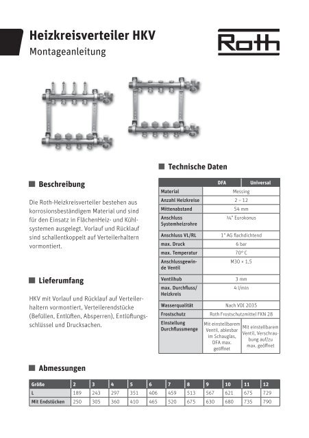
<strong>Heizkreisverteiler</strong> HKV<br />
Montageanleitung<br />
Technische Daten<br />
Beschreibung<br />
Die <strong>Roth</strong>-<strong>Heizkreisverteiler</strong> bestehen aus<br />
korrosionsbeständigem Material und sind<br />
für den Einsatz in FlächenHeiz- und Kühlsystemen<br />
ausgelegt. Vorlauf und Rücklauf<br />
sind schallentkoppelt auf Verteilerhaltern<br />
vormontiert.<br />
Lieferumfang<br />
HKV mit Vorlauf und Rücklauf auf Verteilerhaltern<br />
vormontiert, Verteilerendstücke<br />
(Befüllen, Entlüften, Absperren), Entlüftungsschlüssel<br />
und Drucksachen.<br />
DFA<br />
Universal<br />
Material<br />
Messing<br />
Anzahl Heizkreise 2 – 12<br />
Mittenabstand<br />
54 mm<br />
Anschluss<br />
¾" Eurokonus<br />
Systemheizrohre<br />
Anschluss VL/RL<br />
max. Druck<br />
max. Temperatur<br />
Anschlussgewinde<br />
Ventil<br />
Ventilhub<br />
max. Durchfluss/<br />
Heizkreis<br />
1" AG flachdichtend<br />
6 bar<br />
70 ° C<br />
M30 × 1,5<br />
3 mm<br />
4 l/min<br />
Wasserqualität Nach VDI 2035<br />
Frostschutz <strong>Roth</strong> Frostschutzmittel FKN 28<br />
Einstellung<br />
Durchflussmenge<br />
Mit einstellbarem<br />
Ventil, ablesbar<br />
im Schauglas,<br />
DFA max.<br />
geöffnet<br />
Mit einstellbarem<br />
Ventil, Verschraubung<br />
auf/zu<br />
max. geöffnet<br />
Abmessungen<br />
Größe 2 3 4 5 6 7 8 9 10 11 12<br />
L 189 243 297 351 406 459 513 567 621 675 729<br />
Mit Endstücken 250 305 360 410 465 520 675 630 680 735 790
Abmessungen<br />
mit DFA<br />
4<br />
Universal<br />
3<br />
1 Vorlauf (montiert mit Durchflussanzeigen<br />
oder Verschraubung auf/zu und Anschlussnippeln)<br />
2 Rücklauf (montiert mit einstellbarem<br />
Ventileinsatz und Anschlussnippeln)<br />
3 Verschraubung auf/zu<br />
4 Durchflussanzeige auf/zu (DFA)<br />
5 Anschlussnippel<br />
6 Anschlussnippel DFA<br />
7 Bauschutzkappe<br />
8 Einstellbarer Ventileinsatz für Stellantrieb<br />
9 Verteilerhalter<br />
10 Stellantrieb (nicht im Lieferumfang<br />
enthalten)<br />
11 Endstücke zum Befüllen, Entlüften und<br />
Entleeren<br />
12 Entlüftungsschlüssel<br />
Füllen<br />
1) Kugelhähne am Endstück öffnen, Bauschutzkappe<br />
lösen, DFA oder Verschraubung<br />
auf/zu öffnen<br />
2) Befüllen (Heizkreis für Heizkreis) über den<br />
Vorlauf<br />
3) Bauschutzkappe wieder aufsetzen und<br />
Ventil schließen. Alle weiteren Heizkreise<br />
genauso befüllen.<br />
4) Nach dem Füllen aller Heizkreise die<br />
Kugelhähne am Endstück schließen<br />
Druckprotokoll<br />
Druckprobe Dauer vor und während<br />
der Estrichverlegung<br />
Prüfdruck min. 4 bar - max. 6 bar<br />
Wasserqualität nach VDI 2035<br />
(salzarm) einstellen!<br />
Durchfluss (l/min)<br />
1<br />
10<br />
1<br />
9<br />
2<br />
0,1<br />
10<br />
7<br />
6 5<br />
10<br />
◀1<br />
◀3<br />
8<br />
5 12<br />
Durchflussmengeneinstellung<br />
HKV Universal<br />
Druck (mbar)<br />
◀1<br />
◂3<br />
11<br />
◀1 ◂4<br />
▲ 1<br />
▲ 2<br />
3<br />
▼<br />
Umdrehungen<br />
3,0<br />
2,75<br />
2,5<br />
2,25<br />
2,0<br />
1,75<br />
1,5<br />
1,25<br />
1,0<br />
0,75<br />
60<br />
◀1 ◂4
Einstellen Durchflussmenge/<br />
Heizkreis<br />
Die Durchflussanzeige und die<br />
Verschraubung auf/zu dienen nur zur<br />
Absperrung der Heizkreise!<br />
1) DFA oder Verschraubung auf/zu mit Entlüftungsschlüssel<br />
gegen den Uhrzeigersinn<br />
ganz öffnen<br />
2) Bauschutzkappe am 1. Heizkreis entfernen<br />
und Ventil mit Entlüftungsschlüssel im<br />
Uhrzeigersinn schließen = kleinster Wert<br />
3) Volumenstrom durch Öffnen der Regulierspindel<br />
am Ventil mit Entlüftungsschlüssel<br />
gegen den Uhrzeigersinn einstellen<br />
Durchfluss (l/min)<br />
Gesamtdruckverlust HKV mit DFA<br />
10<br />
1,0<br />
1<br />
10 100<br />
Druck (mbar)<br />
Heizkreise<br />
HK 12<br />
HK 11<br />
HK 10<br />
HK 9<br />
HK 8<br />
HK 7<br />
HK 6<br />
HK 5<br />
HK 4<br />
HK 3<br />
HK 2<br />
HK 1<br />
DFA: Anzahl der Umdrehungen gemäß<br />
Auslegung einstellen und an DFA<br />
ablesen<br />
Mindestdurchfluss ≥ 0,5 l!<br />
Einstellwerte < 0,5 l sind ungenau!<br />
1▶<br />
◀1<br />
Universal: gemäß Auslegung oder<br />
Diagramm 1 ermitteln und einstellen<br />
Mindestdurchfluss ≥ 0,75 Umdrehungen!<br />
Einstellwerte < 0,75 Umdrehungen<br />
sind ungenau!<br />
▲ 2<br />
4 ▼<br />
◂3<br />
Alle weiteren Heizkreise genauso einstellen.<br />
4) Stellantriebe gemäß Montageanleitung<br />
montieren und anschließen
Heating Circuit Manifold HKV<br />
Installation instructions<br />
Technical data<br />
Description<br />
<strong>Roth</strong> heating circuit manifolds are manufactured<br />
from corrosion-resistant material and<br />
are designed for use with floor heating and<br />
cooling systems. Inlet and return are premounted<br />
on manifold brackets with soundinsulation.<br />
Scope of delivery<br />
Heating circuit manifold with inlet and return<br />
premounted on manifold brackets, manifold<br />
end pieces (filling, venting, locking), venting<br />
key and pressure fittings.<br />
Dimensions<br />
Material<br />
Number of<br />
heating circuits<br />
Dual spacing<br />
System heating<br />
pipe connection<br />
LFR<br />
Universal<br />
Brass<br />
2 – 12<br />
54 mm<br />
¾" Euro cone<br />
Inlet/return connection<br />
1" external thread (flat seal)<br />
Max. pressure<br />
6 bar<br />
Max. temperature 70 °C<br />
Valve connection<br />
M30 × 1.5<br />
thread<br />
Valve stroke<br />
Max. flow rate/<br />
heating circuit<br />
3 mm<br />
4 l/min<br />
Water quality In acc. w. VDI 2035<br />
Frost protection <strong>Roth</strong> antifreeze FKN 28<br />
Flow rate setting<br />
With adjustable<br />
valve, screw<br />
With adjustable<br />
valve, sight glass<br />
connection open/<br />
readable, LFR<br />
closed<br />
open to max.<br />
open to max.<br />
Size 2 3 4 5 6 7 8 9 10 11 12<br />
L 189 243 297 351 406 459 513 567 621 675 729<br />
With end pieces 250 305 360 410 465 520 675 630 680 735 790
Dimensions<br />
with LFR<br />
4<br />
3<br />
Universal<br />
1 Inlet (mounted with flow rate displays or<br />
screw connection open/closed and connection<br />
nipples)<br />
2 Return (mounted with adjustable valve<br />
insert and connection nipples)<br />
3 Screw connection open/closed<br />
4 Flow rate display open/closed (LFR)<br />
5 Connection nipple<br />
6 Connection nipple LFR<br />
7 Protection cap<br />
8 Adjustable valve insert for actuator<br />
9 Manifold bracket<br />
10 Actuator (not included in the scope of<br />
delivery)<br />
11 End pieces for filling, venting, and<br />
evacuating<br />
12 Venting key<br />
Filling<br />
1) Open ball valves at end piece, detach protection<br />
cap, open LFR or screw connection<br />
open/closed<br />
2) Filling (one heating circuit after the other)<br />
via the inlet<br />
3) Replace protection cap and close valve.<br />
Proceed similarly for all heating circuits.<br />
4) Close ball valves at the end piece when all<br />
heating circuits are filled<br />
Pressure protocol<br />
Pressure test duration before and<br />
during screed laying Test pressure<br />
min. 4 bar - max. 6 bar Adjust water<br />
quality in acc. w. VDI 2035 (low<br />
salinity)!<br />
Flow rate (l/min)<br />
1<br />
10<br />
1<br />
9<br />
2<br />
0,1<br />
10<br />
7<br />
6 5<br />
10<br />
◀1<br />
◀3<br />
8<br />
5 12<br />
◀1<br />
◂3<br />
11<br />
Flow rate setting HCM Universal<br />
Pressure (mbar)<br />
60<br />
◀1 ◂4<br />
▲ 1<br />
▲ 2<br />
3<br />
▼<br />
◀1 ◂4<br />
Rotations<br />
3,0<br />
2,75<br />
2,5<br />
2,25<br />
2,0<br />
1,75<br />
1,5<br />
1,25<br />
1,0<br />
0,75
Flow rate setting/heating circuit<br />
The flow rate display and the screw connection<br />
open/closed are used only for<br />
locking the heating circuits!<br />
1) Use venting key to fully open (counterclockwise)<br />
LFR or screw connection open/<br />
closed<br />
2) Remove protection cap at 1st heating<br />
circuit, and use the venting key to close<br />
(clockwise) the valve = smallest value<br />
3) Adjust flow rate by opening the control<br />
spindle on the valve using the venting key<br />
(anti-clockwise)<br />
LFR: Adjust number of revolutions in<br />
accordance with schematic and read<br />
value on LFR Min. flow rate ≥ 0.5 l!<br />
Setting values < 0.5 l are inexact!<br />
Flow rate (l/min)<br />
Overall pressure loss HCM with LFR<br />
10<br />
1,0<br />
1<br />
10 100<br />
Pressure (mbar)<br />
1▶<br />
Heating circuits<br />
HC 12<br />
HC 11<br />
HC 10<br />
HC 9<br />
HC 8<br />
HC 7<br />
HC 6<br />
HC 5<br />
HC 4<br />
HC 3<br />
HC 2<br />
HC 1<br />
Universal: determine and set in<br />
accordance with schematics or<br />
diagram 1 Min. flow rate ≥ 0.75<br />
revolutions! Setting values < 0.75<br />
revolutions are inexact!<br />
Proceed similarly for all heating circuits.<br />
▲ 2<br />
4 ▼<br />
◂3<br />
◀1<br />
4) Mount and connect the actuators in accordance<br />
with the assembly instructions
Distributeurs de circuit de<br />
chauffage DCC<br />
Instructions de montage<br />
Caractéristiques techniques<br />
Description<br />
Les distributeurs de circuit de chauffage <strong>Roth</strong><br />
sont fabriqués en matériaux inoxydables<br />
et conçus pour une utilisation dans des<br />
systèmes de chauffage et refroidissement<br />
étendus. Les écoulements et retours sont<br />
prémontés avec isolation acoustique sur les<br />
supports de distributeurs<br />
Étendue de la fourniture<br />
DCC (distributeur de circuit de chauffage)<br />
avec écoulement et retour prémontés sur<br />
supports de distributeur, embouts de distributeur<br />
(remplissage, purge, blocage), clé de<br />
purge et éléments de pression.<br />
Dimensions<br />
DFA<br />
Universel<br />
Matériau<br />
Laiton<br />
Nombre de circuits<br />
2 – 12<br />
de chauffage<br />
Entraxe<br />
54 mm<br />
Raccord des<br />
Eurocône ¾"<br />
tuyaux de chauffage<br />
du système<br />
Raccord CE/CR Filetage mâle 1'', jointage plat<br />
Pression max.<br />
6 bars<br />
Température max. 70 °C<br />
Filetage de<br />
M30 × 1,5<br />
raccordement de<br />
soupape<br />
Course de soupape<br />
3 mm<br />
Débit max./circuit<br />
4 l/min<br />
de chauffage<br />
Qualité de l'eau Selon la norme DIN 2035<br />
Protection contre Antigel <strong>Roth</strong> FKN 28<br />
le gel<br />
Réglage du débit<br />
Avec soupape<br />
réglable, visible<br />
sur le regard, DFA<br />
ouverture max.<br />
Avec soupape<br />
réglable, raccord<br />
ouvert/fermé<br />
ouverture max.<br />
Taille 2 3 4 5 6 7 8 9 10 11 12<br />
L 189 243 297 351 406 459 513 567 621 675 729<br />
Avec embouts 250 305 360 410 465 520 675 630 680 735 790
Dimensions<br />
1 Écoulement (monté avec indicateurs de<br />
débit ou raccord ouvert/fermé et nipples<br />
de raccordement)<br />
2 Écoulement (monté avec insert de soupape<br />
et nipples de raccordement)<br />
3 Raccord ouvert/fermé<br />
4 Indicateur de débit ouvert/fermé (DFA)<br />
5 Nipple de raccordement<br />
6 Nipple de raccordement DFA<br />
7 Capuchon de protection<br />
8 Insert de soupape réglable pour le<br />
servomoteur<br />
9 Support de distributeur<br />
10 Servomoteur (non fourni)<br />
11 Embouts de remplissage, purge et<br />
vidange<br />
12 Clé de purge<br />
Remplir<br />
1) Ouvrir le robinet à bille en extrémité,<br />
dévisser le capuchon de protection, ouvrir<br />
DFA ou raccord ouvert/fermé<br />
2) Remplir (circuit après circuit) via<br />
l'écoulement<br />
3) Remettre le capuchon de protection et<br />
fermer la soupape. Remplir de la même<br />
façon tous les autres circuits de chauffage<br />
4) Après le remplissage de tous les circuits,<br />
fermer les robinets à bille d'extrémité<br />
Rapport de pression<br />
Durée du test de pression avant et<br />
pendant la pose des chapes Pression<br />
de contrôle min. 4 bars - max. 6 bars,<br />
régler la qualité de l'eau selon VDI<br />
2035 (peu saline) !<br />
Débit (l/min)<br />
avec DFA<br />
1<br />
10<br />
1<br />
9<br />
2<br />
0,1<br />
10<br />
7<br />
4<br />
6 5<br />
10<br />
◀1<br />
◀3<br />
Universel<br />
3<br />
8<br />
5 12<br />
Réglage du débit DCC Universal<br />
Pression (mbar)<br />
◀1<br />
◂3<br />
11<br />
◀1 ◂4<br />
▲ 1<br />
▲ 2<br />
3<br />
▼<br />
◀1 ◂4<br />
60<br />
Tours<br />
3,0<br />
2,75<br />
2,5<br />
2,25<br />
2,0<br />
1,75<br />
1,5<br />
1,25<br />
1,0<br />
0,75
Réglage du débit/circuit de<br />
chauffage<br />
L'indicateur de débit et le raccord<br />
ouvert/fermé ne servent qu'au blocage<br />
des circuits de chauffage !<br />
1) Ouvrir entièrement la DFA ou le raccord<br />
ouvert/fermé avec la clé de purge dans le<br />
sens antihoraire.<br />
2) circuit de chauffage et fermer la soupape<br />
avec la clé de purge dans le sens horaire =<br />
plus petite valeur<br />
3) Régler le débit en ouvrant la broche de<br />
régulation sur la soupape à l'aide de la clé<br />
de purge dans le sens antihoraire<br />
Débit (l/min)<br />
Perte totale de pression DCC avec DFA<br />
Circuits de chauffage<br />
HK 12<br />
HK 11<br />
HK 10<br />
HK 9<br />
HK 8<br />
HK 7<br />
HK 6<br />
HK 5<br />
HK 4<br />
10<br />
HK 3<br />
HK 2<br />
HK 1<br />
1,0<br />
1<br />
10 100<br />
Pression (mbar)<br />
DFA : Régler le nombre de tours en<br />
fonction du dimensionnement et lire<br />
sur le DFA débit minimum ≥ 0,5 l !<br />
Les valeurs de réglages < 0,5 l sont<br />
imprécises !<br />
1▶<br />
◀1<br />
Universelle : établir ou régler le<br />
dimensionnement ou le diagramme1<br />
débit minimum ≥ 0,75 tours ! Les<br />
valeurs de réglages < 0,75 tours<br />
sont imprécises !<br />
▲ 2<br />
4 ▼<br />
◂3<br />
Régler de la même façon tous les autres<br />
circuits de chauffage.<br />
4) Monter et raccorder les servomoteurs<br />
conformément à la notice de montage
Collettori del circuito di<br />
riscaldamento HKV<br />
Istruzioni di montaggio<br />
Dati tecnici<br />
Descrizione<br />
I collettori del circuito di riscaldamento <strong>Roth</strong><br />
sono composti da materiale resistente alla<br />
corrosione e concepiti per impiego in sistemi<br />
di riscaldamento e raffrescamento a superficie.<br />
La mandata e il ritorno sono premontati<br />
sui supporti del collettore con isolamento<br />
acustico.<br />
Fornitura<br />
HKV con mandata e ritorno premontato su<br />
supporti del collettore, parti terminali del<br />
collettore (riempimento, sfiato, chiusura),<br />
chiave di sfiato e materiale cartaceo.<br />
Dimensioni<br />
Materiale<br />
Numero circuiti<br />
riscaldanti<br />
Distanza centrale<br />
Collegamento<br />
tubi sistema di<br />
riscaldamento<br />
Collegamento M/R<br />
Pressione max.<br />
Temperatura max.<br />
Filettatura di<br />
collegamento<br />
valvola<br />
Corsa della<br />
valvola<br />
Portata/circuito<br />
riscaldante max.<br />
DFA<br />
Ottone<br />
2 – 12<br />
54 mm<br />
¾" Eurokonus<br />
Universale<br />
1" maschio tenuta piana<br />
6 bar<br />
70 ° C<br />
M30 × 1,5<br />
3 mm<br />
4 l/min<br />
Qualità dell'acqua Conforme a VDI 2035<br />
Antigelo Antigelo <strong>Roth</strong> FKN 28<br />
Regolazione<br />
portata<br />
Con valvola regolabile,<br />
finestrino<br />
per lettura, DFA<br />
max. aperto<br />
Con valvola regolabile,<br />
filettatura<br />
on/off<br />
max. aperta<br />
Dimensioni 2 3 4 5 6 7 8 9 10 11 12<br />
L 189 243 297 351 406 459 513 567 621 675 729<br />
Con terminali 250 305 360 410 465 520 675 630 680 735 790
Dimensioni<br />
1 Mandata (montata con indicazione di<br />
portata o filettatura on/off e nipplo di<br />
collegamento)<br />
2 Ritorno (montato con inserto valvole<br />
regolabile e nipplo di collegamento)<br />
3 Filettatura on/off<br />
4 Indicatore di portata on/off (DFA)<br />
5 Nipplo di collegamento<br />
6 Nipplo di collegamento DFA<br />
7 Calotta di protezione<br />
8 Inserto valvole regolabile per attuatore<br />
9 Supporto collettore<br />
10 Attuatore (non presente in fornitura)<br />
11 Terminali per riempimento, sfiato e svuotamento<br />
12 Chiave di sfiato<br />
Riempimento<br />
Portata (l/min)<br />
con DFA<br />
1<br />
10<br />
1<br />
9<br />
2<br />
7<br />
4<br />
6 5<br />
10<br />
Universale<br />
3<br />
8<br />
5 12<br />
11<br />
Regolazione portata HKV Universale<br />
Giri<br />
3,0<br />
2,75<br />
2,5<br />
2,25<br />
2,0<br />
1,75<br />
1,5<br />
1,25<br />
1,0<br />
0,75<br />
1) Aprire le valvole a sfera del terminale,<br />
allentare la calotta di protezione, aprire<br />
DFA o filettatura on/off<br />
2) Riempire (circuito riscaldante per circuito<br />
riscaldante) mediante la mandata<br />
3) Inserire di nuovo la calotta di protezione<br />
e chiudere la valvola. Riempire secondo lo<br />
stesso procedimento tutti gli altri circuiti<br />
riscaldanti.<br />
4) Dopo il riempimento di tutti i circuiti<br />
riscaldanti chiudere le valvole a sfera del<br />
terminale<br />
Protocollo per la pressione<br />
0,1<br />
10<br />
Pressione (mbar)<br />
60<br />
◀1<br />
◀3 ◀1<br />
◂3<br />
◀1 ◂4<br />
▲ 1<br />
▲ 2<br />
Prova di pressione durata prima e<br />
durante la posa del massetto<br />
regolare pressione di prova min. 4 bar<br />
- max. 6 bar qualità dell'acqua<br />
conforme a VDI 2035 (a basso<br />
contenuto salino)!<br />
3<br />
▼<br />
◀1 ◂4
Regolazione della portata/<br />
circuito riscaldante<br />
L'indicatore della portata e la filettatura<br />
on/off servono solo per bloccare i<br />
circuiti riscaldanti!<br />
1) Aprire DFA o filettatura on/off in senso<br />
antiorario con la chiave di sfiato<br />
2) Rimuovere la calotta di protezione del 1°<br />
circuito riscaldante e chiudere la valvola<br />
con la chiave di sfiato in senso orario =<br />
valore minore<br />
3) Regolare la portata volumetrica aprendo<br />
in senso antiorario il mandrino di regolazione<br />
della valvola con la chiave di sfiato<br />
Portata (l/min)<br />
Perdita di pressione totale HKV con DFA<br />
Circuiti riscaldanti<br />
HK 12<br />
HK 11<br />
HK 10<br />
HK 9<br />
HK 8<br />
HK 7<br />
HK 6<br />
HK 5<br />
HK 4<br />
10<br />
HK 3<br />
HK 2<br />
HK 1<br />
1,0<br />
1<br />
10 100<br />
Pressione (mbar)<br />
DFA: Regolare numero dei giri<br />
secondo la progettazione e leggere su<br />
DFA Portata minima ≥ 0,5 l! Valori di<br />
regolazione < 0,5 l sono imprecisi!<br />
1▶<br />
◀1<br />
Universale: Misurare e regolare in<br />
base alla progettazione o al diagramma<br />
1 Portata minima ≥ 0,75 giri!<br />
Valori di regolazione < 0,75 giri<br />
sono imprecisi!<br />
▲ 2<br />
4 ▼<br />
◂3<br />
Regolare secondo lo stesso procedimento<br />
tutti gli altri circuiti riscaldanti.<br />
4) Montare e collegare gli attuatori secondo<br />
le istruzioni di montaggio<br />
ROTH WERKE GMBH <strong>·</strong> Am Seerain 2 <strong>·</strong> 35232 Dautphetal <strong>·</strong> Telefon: 0 64 66 / 9 22-0 <strong>·</strong> Telefax: 0 64 66 / 9 22-100<br />
Hotline: 0 64 66 / 9 22-266 <strong>·</strong> E-Mail: service@roth-werke.de <strong>·</strong> www.roth-werke.de<br />
Material-Nr.: 1150010384 10113 DB Technische Änderungen vorbehalten.