Bedienungsanleitung OR-T 250 - Schneider Vertrieb
Bedienungsanleitung OR-T 250 - Schneider Vertrieb
Bedienungsanleitung OR-T 250 - Schneider Vertrieb

Create successful ePaper yourself
Turn your PDF publications into a flip-book with our unique Google optimized e-Paper software.
DEUTSCH<br />
ENGLISH<br />
FRANÇAIS<br />
BETRIEBSANLEITUNG<br />
Originalbetriebsanleitung<br />
OPERATING INSTRUCTIONS Translation of original manual<br />
MODE D‘EMPLOI<br />
Traduction du mode d’emploi original<br />
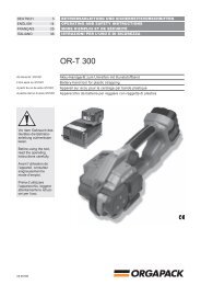
<strong>OR</strong>-T <strong>250</strong><br />
Ab Serie-Nr. B/91001<br />
From series no B/91001<br />
A partir du no de série B/91001<br />
Akku-Handgerät zum Umreifen mit Kunststoffband<br />
Battery-hand tool for plastic strapping<br />
Appareil sur accu pour le cerclage par bande plastique<br />
Vor dem Gebrauch des<br />
Gerätes die Betriebsanleitung<br />
aufmerksam<br />
lesen.<br />
Before using the tool,<br />
read the operating<br />
instructions carefully.<br />
Avant l’utilisation de<br />
l’appareil, consultez<br />
soigneusement le<br />
mode d’emploi.<br />
Patent angemeldet<br />
Patent pending<br />
Brevet en cours<br />
09.09/WE
1. 3.<br />
Akku laden / Charging battery / Charger l‘accu<br />
2.<br />
KURZANLEITUNG<br />
Das Wichtigste in Kürze!<br />
Akku einsetzen / Insert battery / Enfoncer l‘accu<br />
rot / red / rouge<br />
Fehler / Error / Erreur<br />
grün / green vert<br />
+<br />
Aufl aden ca. 20–40 min.<br />
1. Laden > 5 Std. /<br />
Recharger Recharging env. approx. 20–40 20–40 min. min.<br />
1st charge > 5 hr /<br />
1. Charger > 5 h /<br />
✓<br />
Gerät ist eingeschaltet<br />
Tool is switched on<br />
L‘appareil est mis on circuit<br />
Bedienung / Operation / Mode d‘emploi<br />
1. 2.<br />
Betriebsart: / Mode of operation: / Mode d‘exploitation:<br />
Halbautomatisch / Semi-Auto / Semi-Automatique<br />
MAN. +<br />
AUTO<br />
3. 4.<br />
➟Spannen ➟Schweissen / Tensioning / Welding / Tension Soudage<br />
2 09.09/WE
SH<strong>OR</strong>T INSTRUCTIONS<br />
The most important points in brief!<br />
Bedienpanel / Operating panel / Panneau<br />
AUTO<br />
MAN.<br />
SOFT<br />
+ / -<br />
+ / -<br />
AUTO<br />
MAN.<br />
SOFT<br />
Spannkraft / Tension force / Force de tension<br />
➟<br />
+ / -<br />
1<br />
LED Anzeige / LED Display / Affi chage DEL:<br />
=<br />
9<br />
ca. 900 N (200 lbs.) Soft 400 N (88 lbs.)<br />
=<br />
ca. <strong>250</strong>0 N (560 lbs.) Soft 1500 N (335 lbs.)<br />
Schweisszeit / Welding time / Durée de soudage<br />
➟<br />
+ / -<br />
1<br />
LED<br />
7<br />
Anzeige / LED Display / Affi chage DEL:<br />
= min.<br />
= max.<br />
➟<br />
➟<br />
➟<br />
➟<br />
INSTRUCTIONS ABRÉGÉES<br />
Le plus important en bref!<br />
Akku-Ladezustand / Battery charge / Charge de l‘accu<br />
grün / green / vert<br />
Betriebsart / Mode of operation / Mode d‘exploitation<br />
AUTO<br />
MAN.<br />
Halbautomatisch / Semi-Auto<br />
SOFT<br />
/ Semi- Automatique:<br />
AUTO<br />
MAN.<br />
SOFT<br />
AUTO<br />
Vollautomatisch / Fully-Auto / Entièrement automatique:<br />
AUTO<br />
MAN.<br />
SOFT<br />
AUTO<br />
MAN.<br />
SOFT<br />
AUTO<br />
MAN.<br />
SOFT<br />
✓<br />
+<br />
✓<br />
AUTO<br />
blinkend / fl ashing /<br />
Manuell<br />
clignote<br />
/ Manual / Manuel:<br />
MAN.<br />
➟<br />
MAN.<br />
➟ Aufl aden<br />
➟ Recharge<br />
➟ Recharger<br />
rot / red / rouge<br />
=<br />
=<br />
=<br />
1.<br />
Softspannung / Soft tension / Tension soft:<br />
(PP Band / PP straps / Bande PP)<br />
SOFT<br />
=<br />
2.<br />
Für weiche Packgüter<br />
For soft packages<br />
Pour paquets souples<br />
Kontrolle / Checking seal / Vérification du sertissage<br />
Gute Schweissung / Good seal / Bonne soudure<br />
Schlechte Schweissung / Poorly welded seal /<br />
Mauvaise soudure<br />
siehe Für Betriebsanleitung detaillierte Beschreibung, ab Seite 4!<br />
see operating For detailed instructions description, from page 4!<br />
voir Pour mode description d‘emploi à détaillée, partir page 4!<br />
09.09/WE<br />
3
<strong>OR</strong>GAPACK <strong>OR</strong>-T <strong>250</strong><br />
CH<br />
<strong>OR</strong>GAPACK GmbH<br />
Packaging Technology<br />
Silbernstrasse 14<br />
CH-8953 Dietikon<br />
Telefon +41 1 745 50 50<br />
Fax +41 1 745 52 64<br />
e-mail pt@orgapack.com<br />
Internet www.orgapack.com<br />
Zertifi kat ISO 9001 / EN 29001<br />
INHALTSVERZEICHNIS<br />
Seite<br />
KURZANLEITUNG 2<br />
1 Technische Daten 6<br />
2 Allgemeines 8<br />
2.1 Hinweise zum Umweltschutz 8<br />
3 Sicherheitsvorschriften 10<br />
4 Beschreibung 12<br />
4.1 Aufbau 12<br />
4.2 Bedienpanel 12<br />
4.3 Funktionsprinzip 12<br />
5 Bedienung 14<br />
5.1 Akku aufl aden 14<br />
5.2 Bedienung des Gerätes 14<br />
5.3 Verschlusskontrolle 18<br />
5.4 Akku-Ladezustand prüfen 18<br />
5.5 Betriebsarten einstellen 18<br />
5.6 Spannkraft einstellen 20<br />
5.7 Softspannung einstellen 20<br />
5.8 Schweisszeit einstellen 20<br />
5.9 Bandbreite einstellen 20<br />
6 Sonderfunktionen 22<br />
6.1 Tastensperre ein- und ausschalten 22<br />
6.2 Schlafmodus 22<br />
6.3 Geräte-Reset 22<br />
7 Wartung und Instandsetzung 24<br />
7.1 Spannrad reinigen/ersetzen 24<br />
7.2 Zahnplatte reinigen/ersetzen 24<br />
7.3 Messer ersetzen 24<br />
7.4 Beheben von Störungen 26<br />
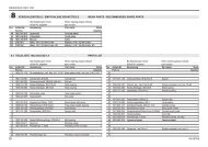
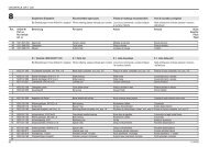
8 Verschleissteile / Empfohlene Ersatzteile 28<br />
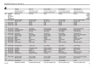
8.1 Teileliste 28<br />
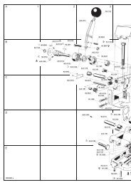
Explosionszeichnung 32<br />
KONF<strong>OR</strong>MITÄTSERKLÄRUNG<br />
Wir erklären in alleiniger Verantwortung, dass das<br />
Gerät <strong>OR</strong>-T <strong>250</strong>, auf welches sich diese Erklärung<br />
bezieht, mit den geltenden Bestimmungen der Richtlinie<br />
des Rates vom 17. Mai 2006 (2006/42/EG) „Maschinen-<br />
Richtlinie“ und deren Änderungen übereinstimmt.<br />
Im weiteren gilt die Übereinstimmung mit den geltenden<br />
Bestimmungen der Richtlinie des Rates vom 12.<br />
Dezember 2006 (2006/95/EG) „Niederspannungs-<br />
Richtlinie“ und vom 15. Dezember 2004 (2004/108/EG)<br />
„EMV-Richtlinie“.<br />
Berücksichtigte Normen:<br />
EN ISO 12100-1, EN ISO 12100-2, EN 349,<br />
EN ISO 14121-1, EN 61000-6-1, EN 61000-6-3<br />
EG-Baumusterbescheinigung: Nr. 1101<br />
Zertifi zierungsstelle: NSBIV AG, SIBE Schweiz<br />
CH-8953 Dietikon, 04.09.2009<br />
General Manager General Manager Products<br />
Packaging Technology: Packaging Technology:<br />
U. Schweizer M. Binder<br />
4 09.09/WE
<strong>OR</strong>GAPACK <strong>OR</strong>-T <strong>250</strong><br />
TABLE OF CONTENTS<br />
Page<br />
SH<strong>OR</strong>T INSTRUCTIONS 2<br />
1 Technical data 7<br />
2 General information 9<br />
2.1 Information on environmental protection 9<br />
3 Safety instructions 11<br />
4 Description 13<br />
4.1 Construction 13<br />
4.2 Operating panel 13<br />
4.3 Function 13<br />
5 Operating instructions 15<br />
5.1 Charging the battery 15<br />
5.2 Operating the tool 15<br />
5.3 Checking the seal 19<br />
5.4 Checking battery charge 19<br />
5.5 Setting mode of operation 19<br />
5.6 Setting strap tension 21<br />
5.7 Setting soft tension 21<br />
5.8 Setting welding time 21<br />
5.9 Setting strap width 21<br />
6 Special functions 23<br />
6.1 Switch touch-pad lock on and off 23<br />
6.2 Sleep mode 23<br />
6.3 Tool reset 23<br />
7 Preventive and corrective maintenance 25<br />
7.1 Cleaning/replacing tension wheel 25<br />
7.2 Cleaning/replacing tooth plate 25<br />
7.3 Replacing knife 25<br />
7.4 Trouble shooting 27<br />
8 Wear parts / Recommended spare parts 28<br />
8.1 Parts list 28<br />
Exploded drawing 32<br />
DECLARATION OF CONF<strong>OR</strong>MITY<br />
We take sole responsibility for declaring that the tool<br />
<strong>OR</strong>-T <strong>250</strong> to which this declaration refers is in full<br />
conformity with the current requirements of the<br />
guidelines laid down by the council on 17th May 2006<br />
(2006/42/ECC), “Machine Guidelines“.<br />
Furthermore, electrical installations are in conformity<br />
with the guideline laid down by the council on 12.<br />
December 2006 (2006/95/EEC) “Low Voltage Guidelines“<br />
and 15. December 2004 (2004/108/EEC)<br />
“EMV Guidelines“.<br />
Harmonised standards applied:<br />
EN ISO 12100-1, EN ISO 12100-2, EN 349,<br />
EN ISO 14121-1, EN 61000-6-1, EN 61000-6-3<br />
EEC-Design certifi cation: No 1101<br />
Place of certifi cation: NSBIV AG, SIBE CH<br />
TABLE DES MATIÈRES<br />
Page<br />
INSTRUCTIONS ABRÉGÉES 2<br />
1 Données techniques 7<br />
2 Instructions générales 9<br />
2.1 Remarque à la protection de l‘environnement 9<br />
3 Instructions de sécurité 11<br />
4 Description 13<br />
4.1 Modules principaux 13<br />
4.2 Panneau de commande 13<br />
4.3 Fonctionnement 13<br />
5 Mode d‘emploi 15<br />
5.1 Chargeur d’accumulateur 15<br />
5.2 Mode d’emploi pour l’appareil 15<br />
5.3 Vérifi cation du sertissage 19<br />
5.4 Vérifi cation de l’état de charge de l’accu 19<br />
5.5 Réglage mode d‘exploitation 19<br />
5.6 Réglage de la force de tension 21<br />
5.7 Réglage de la tension soft 21<br />
5.8 Réglage de la durée de soudage 21<br />
5.9 Réglage de la largeur de bande 21<br />
6 Fonctions spéciales 23<br />
6.1 Verrouillage des touches ON/OFF 23<br />
6.2 Mode sommeil 23<br />
6.3 Réinitialisation de l‘appareil 23<br />
7 Instructions de service 25<br />
7.1 Nettoyage/rempl. de la molette de tension 25<br />
7.2 Nettoyage/rempl. de la plaque dentée 25<br />
7.3 Remplacement du couteau 25<br />
7.4 Dépannage 27<br />
8 Pièces d‘usure / Pièces de rechange rec. 28<br />
8.1 Liste des pièces 28<br />
Vue éclatée 32<br />
DÉCLARATION DE CONF<strong>OR</strong>MITÉ<br />
Nous déclarons sous notre propre responsabilité que<br />
l‘appareil <strong>OR</strong>-T <strong>250</strong> ci-dessus, au sujet auquel se réfère<br />
cette déclaration, est conforme aux prescriptions en<br />
vigueur de la directive du conseil du 17 mai 2006<br />
(2006/42/CEE) “Directive pour machines“.<br />
En outre, la conformité est valable avec les prescriptions<br />
en vigueur de la directive du conseil du 12 décembre<br />
2006 (2006/95/CEE) “Directive pour basse tension“<br />
et du 15 décembre 2004 (2004/108/CEE) “Directive<br />
EMV“.<br />
Normes considerées:<br />
EN ISO 12100-1, EN ISO 12100-2, EN 349,<br />
EN ISO 14121-1, EN 61000-6-1, EN 61000-6-3<br />
CEE-Certifi cat de modéle: No 1101<br />
Buerau de certifcation: NSBIV AG, SIBE Suisse<br />
CH-8953 Dietikon, 04.09.2009<br />
General Manager<br />
Packaging Technology:<br />
General Manager Prod.<br />
Packaging Technology:<br />
CH-8953 Dietikon, 04.09.2009<br />
General Manager<br />
General Manager<br />
Packaging Technology: Packaging Technology:<br />
U. Schweizer M. Binder<br />
09.09/WE<br />
U. Schweizer M. Binder<br />
5
<strong>OR</strong>GAPACK <strong>OR</strong>-T <strong>250</strong><br />
1 TECHNISCHE DATEN<br />
Gewicht<br />
Abmessungen<br />
Spannkraft<br />
Spanngeschwindigkeit<br />
Verschluss<br />
3,9 kg (inkl. Akku)<br />
Länge 334 mm<br />
Breite 138 mm<br />
Höhe 148 mm<br />
(0) 900–<strong>250</strong>0 N<br />
Soft: 400–1500 N<br />
220 mm/s<br />
Reibschweissverschluss<br />
Gemessener A-bewerteter<br />
Emissions-Schalldruckpegel<br />
(EN ISO 11202) L pA<br />
79 dB (A)<br />
Hand-Arm-Schwingungen<br />
(EN ISO 8662-1) a h,w<br />
2,2 ms -2<br />
Einsatztemperatur –10 °C bis +40 °C<br />
Relative Luftfeuchtigkeit Bis 90 %<br />
LADEGERÄT / AKKU<br />
Stromart Ladegerät<br />
Ladegerät Typ<br />
Ladezeit<br />
Anzahl<br />
Umreifungen<br />
pro Ladung<br />
Akku<br />
100 / 110 / 230 V<br />
BOSCH AL 1860 CV<br />
20–45 Minuten,<br />
nach 20 min ca. 70%<br />
Ladekapazität<br />
200 bis 400 je nach<br />
Bandqualität, Spannkraft<br />
und Packgut<br />
14,4 V / 2,6 Ah, Li-Ion<br />
BOSCH<br />
KUNSTSTOFFBAND<br />
Bandqualität<br />
Bandbreite<br />
einstellbar auf<br />
Banddicke<br />
Polypropylen (PP)<br />
Polyester (PET)<br />
12–13, 15–16 mm<br />
(Option: 9–11 mm)<br />
0,5–1,0 mm<br />
6 09.09/WE
<strong>OR</strong>GAPACK <strong>OR</strong>-T <strong>250</strong><br />
1 TECHNICAL DATA 1 DONNÉES TECHNIQUES<br />
Weight<br />
3.9 kg (8.6 lbs.)<br />
(incl. battery)<br />
Poids<br />
3,9 kg<br />
(incl. accumulateur)<br />
Dimensions Length 334 mm (13.1“)<br />
Width 138 mm (5.4“)<br />
Height 148 mm (5.8“)<br />
Encombrement<br />
Longueur 334 mm<br />
Largeur 138 mm<br />
Hauteur 148 mm<br />
Strap tension<br />
(0) 900–<strong>250</strong>0 N (200–560 lbs.)<br />
Soft: 400–1500 N (88–335 lbs.)<br />
Force de tension<br />
(0) 900–<strong>250</strong>0 N<br />
Soft: 400–1500 N<br />
Tension speed<br />
220 mm/s (8.6“/s)<br />
Vitesse de tension<br />
220 mm/s<br />
Sealing<br />
Friction weld<br />
Sertissage<br />
Soudage à friction<br />
Emission sound pressure<br />
levels, measurement<br />
type A (EN ISO 11202) L pA<br />
79 dB (A)<br />
Vibrations at handle<br />
(EN ISO 8662-1) a h,w<br />
2.2 ms -2<br />
Working temperature –10 °C up to +40 °C<br />
(14 °F up to 104 °F)<br />
Relative humidity Up to 90 %<br />
BATTERY CHARGER / BATTERY<br />
Niveaux de pression<br />
acoustique, evaluation<br />
type A (EN ISO 11202) L pA<br />
79 dB (A)<br />
Vibrations au niveau des<br />
poignées (EN ISO 8662-1)a h,w<br />
2,2 ms -2<br />
Température d‘application –10 °C à +40 °C<br />
Humidité relative Jusqu‘à 90 %<br />
CHARGEUR / ACCUMULATEUR<br />
Battery charger voltage<br />
100 / 110 / 230 V<br />
Tension électrique chargeur<br />
100 / 110 / 230 V<br />
Battery charger type<br />
BOSCH AL 1860 CV<br />
Type de chargeur<br />
BOSCH AL 1860 CV<br />
Charging time<br />
20–45 minutes,<br />
after 20 min approx. 70%<br />
charging capacity<br />
Durée de recharge<br />
20–45 minutes,<br />
Après 20 min. env. 70%<br />
de la capacité de charge<br />
Strappings with<br />
one battery charge<br />
200 to 400 depending on<br />
strap, strap tension and<br />
package<br />
Nombre de cerclages<br />
par charge<br />
200–400 selon la bande,<br />
force de tension, et<br />
paquet<br />
Battery<br />
14.4 V / 2.6 Ah, Li-Ion<br />
BOSCH<br />
Accumulateur<br />
14,4 V / 2,6 Ah, Li-Ion<br />
BOSCH<br />
PLASTIC STRAP<br />
BANDES PLASTIQUES<br />
Strap quality<br />
Strap width<br />
adjustable to<br />
Polypropylene (PP)<br />
Polyester (PET)<br />
12–13, 15–16 mm<br />
( 1 / 2<br />
“, 5 / 8<br />
“)<br />
(option: 9–11 mm)<br />
( 3 / 8<br />
“)<br />
Qualité de bande<br />
Largeur de bande<br />
réglable à<br />
Epaisseur de bande<br />
Polypropylène (PP)<br />
Polyester (PET)<br />
12–13, 15–16 mm<br />
(option: 9–11 mm)<br />
0,5–1,0 mm<br />
Strap thickness 0.5–1.0 mm (.019“–.040“)<br />
09.09/WE<br />
7
<strong>OR</strong>GAPACK <strong>OR</strong>-T <strong>250</strong><br />
2 ALLGEMEINES<br />
Diese Betriebsanleitung soll das Kennenlernen des Gerätes<br />
und den bestimmungsgemässen Einsatz erleichtern.<br />
Die Betriebsanleitung enthält wichtige Hinweise,<br />
wie das Gerät sicher, sachgerecht und wirtschaftlich<br />
einzusetzen ist.<br />
Die Betriebsanleitung muss am Einsatzort des Gerätes<br />
verfügbar sein. Sie ist von allen Personen zu lesen und<br />
anzuwenden, die mit dem Gerät arbeiten.<br />
Neben der Betriebsanleitung und den im Verwenderland<br />
und an der Einsatzstelle geltenden Regelungen zur Unfallverhütung<br />
sind auch die anerkannten fachtechnischen<br />
Regeln für sicherheits- und fachgerechtes Arbeiten zu<br />
beachten.<br />
V<strong>OR</strong>SICHT!<br />
Wird verwendet bei Gefahren für Leben und Gesundheit.<br />
ACHTUNG!<br />
Wird verwendet bei Gefahren, die Sachschäden verursachen<br />
können.<br />
HINWEIS!<br />
Wird verwendet für allgemeine Hinweise und für Hinweise,<br />
bei deren Nichtbeachtung Störungen im Betriebsablauf<br />
entstehen können.<br />
2.1 HINWEISE ZUR ENTS<strong>OR</strong>GUNG<br />
UND UMWELTSCHUTZ<br />
Für die Herstellung des Gerätes werden keine gesundheitsschädigenden<br />
physikalischen oder chemischen<br />
Stoffe verwendet.<br />
Für die Entsorgung sind die gültigen gesetzlichen<br />
Vorschriften zu berücksichtigen. Die Elektrobaugruppen<br />
sind so zu zerlegen, dass die mechanischen, die<br />
elektromechanischen und elektronischen Komponenten<br />
separat entsorgt werden können.<br />
Ladegerät und Akkus sollen einer umweltgerechten<br />
Wiederverwertung zugeführt werden.<br />
• Akku nicht öffen.<br />
• Werfen Sie den verbrauchten Akku nicht in den Hausmüll,<br />
ins Feuer oder ins Wasser.<br />
Defekte, nicht mehr gebrauchte Akkus werden einem<br />
vollständigen Recycling zugeführt.<br />
8 09.09/WE
<strong>OR</strong>GAPACK <strong>OR</strong>-T <strong>250</strong><br />
2 GENERAL INFROMATION<br />
These operating instructions are intended to simplify familiarisation<br />
with the strapping tool and its proper use for<br />
the intended purpose. The operating instructions contain<br />
important information concerning the safe, proper and<br />
effi cient use of the strapping tool.<br />
The operating instructions must always be available at<br />
the place of operation of the strapping tool. They must be<br />
read and observed by all persons working with or on the<br />
strapping tool.<br />
In addition to the operating instructions and the regulations<br />
for accident prevention effective in the country of<br />
use and place of operation, the recognised technical<br />
regulations for safety and proper operation must also be<br />
observed.<br />
CAUTION!<br />
Used where there is danger to life and health.<br />
2 INSTRUCTIONS GÉNÉRALES<br />
Ces instructions de service doivent faciliter la connaissance<br />
de l‘appareil et les possibilités d‘utilisation<br />
selon les règles. Les instructions de service contiennent<br />
d‘importants renseignements, à savoir comment<br />
l‘appareil doit fonctionner en toute sécurité, selon les<br />
critères professionnels et d‘une manière économique.<br />
Les instructions de service doivent constamment être<br />
à disposition sur le lieu d‘utilisation de l‘appareil. Elles<br />
doivent être lues et appliquées par toutes les person-nes<br />
qui sont chargées de travaux sur l‘appareil.<br />
En plus des instructions de service et des règlements<br />
pour la protection contre les accidents valables dans le<br />
pays et à l‘endroit d‘utilisation, il faut également appliquer<br />
les règles de sécurité techniques pour un travail<br />
professionnel et en sécurité.<br />
PRUDENCE!<br />
Utilisé si risque de mort ou d‘atteinte à la santé.<br />
WARNING!<br />
Used for danger which can cause material damage.<br />
ATTENTION!<br />
Utilisé si risque de casse matérielle.<br />
NOTE!<br />
Used for general information and information which, if<br />
not followed can cause faults in the operating sequence.<br />
REMARQUE!<br />
Utilisé pour les remarques générales et pour les remarques<br />
qui, si on ne les respecte pas, entraînent des<br />
dysfonctionnements.<br />
2.1 INF<strong>OR</strong>MATION ON DISPOSAL AND<br />
ENVIRONMENTAL PROTECTION<br />
This tool is manufactured without any physical or chemical<br />
substances which could be dangerous to health.<br />
The legal prescriptions for disposal of all the parts must<br />
be observed. The electrical assemblies should be dismantled<br />
so that the mechanical, electro-mechanical and<br />
electronic components can be disposed of separately.<br />
2.1 REMARQUE RELATIVE À LA PROTECTION DE<br />
L‘ENVIRONNEMENT ET DES DÉCHETS<br />
Cet appareil est fabriqué sans aucun matériau nuisible<br />
pour la santé.<br />
L‘élimination de cet appareil doit être effectuée en<br />
respectant les lois nationales. Les parties électriques<br />
de la construction peuvent être démontées pour que les<br />
composants mécaniques, électromécaniques et électroniques<br />
puissent être triés séparément.<br />
Charger and batteries should be sorted for environmental-friendly<br />
recycling.<br />
• Do not open the battery.<br />
• Do not throw the used battery into household waste,<br />
fi re or water.<br />
Defective or used batteries undergo a complete recycling<br />
process.<br />
09.09/WE<br />
Le chargeur et les accumulateurs doivent pouvoir<br />
suivre chacun une voie de recyclage appropriée.<br />
• Ne pas ouvrir l‘accumulateur.<br />
• Ne jetez les accumulateurs usagés ni aux ordures, ni<br />
au feu, ni dans l‘eau.<br />
Les accumulateurs défectueux récupérés subissent un<br />
recyclage complet.<br />
9
<strong>OR</strong>GAPACK <strong>OR</strong>-T <strong>250</strong><br />
3 SICHERHEITSV<strong>OR</strong>SCHRIFTEN<br />
Informieren Sie sich!<br />
Vor dem Gebrauch des Gerätes die Betriebsanleitung<br />
sorgfältig lesen.<br />
Das Gerät darf nur von ausgebildetem Personal gewartet<br />
und instandgesetzt werden.<br />
Schützen Sie sich!<br />
Beim Arbeiten Augen-, Gesichts-, Handschutz (schnittfeste<br />
Handschuhe) und Sicherheitsschuhe tragen.<br />
Energiequelle!<br />
Vor Wartungs- und Instandsetzungsarbeiten: Akku aus<br />
dem Gerät ziehen. Kontrollieren Sie vor jeder Benutzung<br />
Stecker und Kabel und lassen Sie diese bei Beschädigung<br />
von einem Fachmann ersetzen.<br />
Achtung:<br />
Band springt auf!<br />
Beim Durchschneiden des Bandes den oberen Teil<br />
festhalten und abseits stehen.<br />
Achtung:<br />
Der untere Bandteil wird aufspringen.<br />
Achtung:<br />
Band kann reissen!<br />
Beim Spannen kann das Band reissen! Nicht in der<br />
Flucht des Bandes stehen.<br />
Vorsicht:<br />
Nur Packgut umreifen!<br />
Während dem Umreifen dürfen sich keine Hände und andere<br />
Körperteile zwischen Band und Packgut befi nden.<br />
Vorsicht: Quetschgefahr!<br />
Mit den Fingern nicht in den Spannrad-Bereich greifen.<br />
Kein Wasser verwenden!<br />
Zum Reinigen des Gerätes dürfen weder Wasser noch<br />
Wasserdampf verwendet werden.<br />
Original<br />
<strong>OR</strong>GAPACK<br />
Verwenden Sie nur Original-<strong>OR</strong>GAPACK-Ersatzteile!<br />
Die Verwendung von anderen als <strong>OR</strong>GAPACK-Ersatzteilen<br />
schliesst Garantieleistungen und Haftpfl icht aus.<br />
Bestimmungsgemässe Verwendung<br />
Dieses Gerät ist zum Umreifen von Paketen, Palettenladungen<br />
usw. bestimmt.<br />
Das Gerät ist für das Umreifen mit Verpackungs-Kunststoffbändern<br />
(Polypropylen und Polyester) bestimmt.<br />
Möglicher Missbrauch<br />
Das Umreifen mit Stahlband ist mit diesem Gerät nicht<br />
möglich.<br />
10 09.09/WE
<strong>OR</strong>GAPACK <strong>OR</strong>-T <strong>250</strong><br />
3 SAFETY INSTRUCTIONS<br />
3 INSTRUCTIONS DE SÉCURITÉ<br />
Inform yourself!<br />
Read the operating instructions carefully.<br />
Preventive and corrective maintenance on the tool may<br />
only be carried out by trained personnel.<br />
Protect yourself!<br />
When operating the tool, wear eye, face, hand protection<br />
(cut-proof gloves) and safety shoes.<br />
Power source!<br />
Before starting preventive or corrective maintenance, remove<br />
battery from the tool. Always inspect the electrical<br />
plug and cable before use. If damaged, they must be<br />
replaced by qualifi ed personnel.<br />
Warning:<br />
Strap will snap forward!<br />
When cutting the strap, hold the upper portion and stand<br />
safely away from the strap.<br />
Caution:<br />
The lower strap will snap forward.<br />
Warning:<br />
Strap could break!<br />
Do not stand in line with the strap while it is tensioned.<br />
The strap could break!<br />
Caution:<br />
Only strap packed goods!<br />
Do not put hands or other parts of the body between the<br />
strap and the package during the strapping process.<br />
Caution:<br />
Danger of crushing!<br />
Do not put your fi ngers into the tension wheel area.<br />
Do not use water!<br />
Do not use water or steam to clean the tool.<br />
Renseignez-vous!<br />
Avant l‘utilisation de l‘appareil, consultez soigneusement<br />
le mode d‘emploi. La maintenance et la remise en état<br />
de l’appareil doivent être effectuées exclusivement par<br />
un professionnel ayant suivi une formation adéquate.<br />
Protégez-vous!<br />
Pendant le travail, portez des protections pour les yeux,<br />
le visage les mains (gants de sécurité) et chaussures de<br />
sécurité.<br />
Alimentation!<br />
Enlevez l‘accumulateur de l‘appareil avant chaque travail<br />
de maintenance ou de réparation. Avant toute utilisation,<br />
vérifi er le bon état de la prise et du câble électrique. S‘ils<br />
sont défectueux, les faire remplacer par un professonnel.<br />
Attention:<br />
La bande saute!<br />
En coupant la bande, restez de côté et retenez bien le<br />
brin supérieur de la bande.<br />
Attention:<br />
Soyez prudent, le brin inférieur sautera en avant.<br />
Attention: La bande peut se rompre!<br />
Ne restez jamais dans l’axe de la bande quand celle-ci<br />
est tendue, car la bande peut se casser quand elle est<br />
tendue.<br />
Prudence:<br />
Cercler uniquement le paquet!<br />
Ne mettez ni la main, ni d‘autres parties du corps entre la<br />
bande et l‘emballage.<br />
Prudence:<br />
Danger d‘écrasement!<br />
Ne touchez ni la molette, ni son environnement immédiat<br />
avec les doigts.<br />
Ne pas utiliser de l‘eau!<br />
Ne pas utiliser de l‘eau ou de la vapeur d‘eau pour<br />
nettoyer la machine.<br />
Only original <strong>OR</strong>GAPACK spare parts may be used!<br />
Using non-original spare parts will void the warranty and<br />
any liability.<br />
N‘utilisez que des pièces de rechange d‘origine<br />
<strong>OR</strong>GAPACK!<br />
En cas contraire <strong>OR</strong>GAPACK peut refuser les prestations<br />
de garantie.<br />
Use for the intended purpose<br />
This tool is designed for strapping packages, pallet loads<br />
and the like.<br />
The tool is designed for use with plastic straps (polypropylene<br />
and polyester).<br />
Possible misuse<br />
The use of steel straps is not possible.<br />
09.09/WE<br />
Utilisation conforme<br />
Cet appareil a été conçu pour le cerclage de paquets ou<br />
de palettes.<br />
L‘appareil est destiné au cerclage des emballages avec<br />
des bandes en plastique (polypropylène et polyester).<br />
Utilisation abusive<br />
Le cerclage avec du feuillard d‘acier est impossible avec<br />
cet appareil.<br />
11
<strong>OR</strong>GAPACK <strong>OR</strong>-T <strong>250</strong><br />
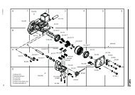
4 BESCHREIBUNG<br />
1<br />
4<br />
4.1 AUFBAU<br />
AUTO<br />
MAN.<br />
SOFT<br />
+ / -<br />
+ / -<br />
AUTO<br />
MAN.<br />
SOFT<br />
2<br />
3<br />
6<br />
5<br />
9<br />
1 Bedienpanel<br />
2 Spanntaste „Band Spannen/Schweissen“ (Vollautom.)<br />
3 Traggriff<br />
4 Akku, 14,4 V<br />
5 Wippenhebel<br />
6 Schweisstaste “Schweissen/Abschneiden“ (Manuell)<br />
7 Schweissen/Abschneiden<br />
8 Spannen<br />
9 Akku Ladegerät<br />
Für detaillierte Angaben, siehe separat beiliegende<br />
Betriebsanleitung für den Akku und das Ladegerät.<br />
7<br />
8<br />
Fig. 1<br />
1 2 3<br />
4.2 BEDIENPANEL<br />
9<br />
8<br />
7<br />
6<br />
AUTO<br />
MAN.<br />
SOFT<br />
+ / -<br />
+ / -<br />
5<br />
AUTO<br />
MAN.<br />
SOFT<br />
4<br />
1 LED-Anzeige „Akku-Ladezustand“<br />
2 Drucktaste „Spannkraft“<br />
3 Drucktaste „Funktion“<br />
4 Drucktaste „Betriebsart“<br />
5 Drucktaste „Schweisszeit“<br />
6 LED-Anzeige „Softspannung“<br />
7 LED-Anzeige „Manuelles Umreifen“ (grünes<br />
Dauerlicht)<br />
8 LED-Anzeige für:<br />
– Halbautomatisches Umreifen (grünes Dauerlicht)<br />
– Vollautomatisches Umreifen (grünes Blinklicht)<br />
9 Segment-Anzeige für:<br />
– Spannkraft (1–9)<br />
– Schweisszeit (1–7)<br />
– Abkühlzeit (count down 3,2,1)<br />
– Fehleranzeige<br />
Fig. 2<br />
Für die einzelnen Beschreibungen/Einstellungen,<br />
siehe Kapitel 5 und 6.<br />
4.3 FUNKTIONSPRINZIP<br />
1 2<br />
3<br />
4<br />
– Festklemmen der Bänder durch Zahnplatte in<br />
Wippe (3/1).<br />
– Spannen über Spannrad (3/2) im Gegenuhrzeigersinn.<br />
– Verschweissen der Bänder im Reibschweissverfahren<br />
(3/3).<br />
– Mit Abschneidmesser (3/4) oberes Band abschneiden.<br />
Fig. 3<br />
12 09.09/WE
<strong>OR</strong>GAPACK <strong>OR</strong>-T <strong>250</strong><br />
4 DESCRIPTION 4 DESCRIPTION<br />
4.1 CONSTRUCTION<br />
1 Operating panel<br />
2 Tension button „Strap tensioning/welding“ (Fully-Auto)<br />
3 Handle<br />
4 Battery, 14.4 V<br />
5 Rocker lever<br />
6 Welding button „Welding/cutting“ (manual)<br />
7 Welding/Cutting<br />
8 Tensioning<br />
9 Battery charger<br />
For detailed information, refer to the operating instructions<br />
for the battery and battery charger.<br />
4.1 MODULES PRINCIPAUX<br />
1 Panneau de commande<br />
2 Bouton de tension „Tension de la bande/Soudage“ (Auto)<br />
3 Poignée<br />
4 Accumulateur, 14,4 V<br />
5 Levier de bascule<br />
6 Bouton de soudage “soudage/coupe“ (manuel)<br />
7 Dispositif de soudage et coupe<br />
8 Serrage<br />
9 Chargeur<br />
Pour les descriptions détaillés, consulter le mode<br />
d’emploi séparé pour l‘accumulateur et le chargeur.<br />
4.2 OPERATING PANEL<br />
1 LED indicator „Battery charge“<br />
2 Push button „Strap tension“<br />
3 Push button „Function“<br />
4 Push button „Mode of operation“<br />
5 Push button „Welding time“<br />
6 LED indicator „Soft tension“<br />
7 LED indicator „Manual strapping“ (continuous<br />
green light)<br />
8 LED indicator for:<br />
– Semi-Automatic strapping (continuous green light)<br />
– Full-Automatic strapping (fl ashing green light)<br />
9 Digital display for:<br />
– Strap tension (1–9)<br />
– Welding time (1–7)<br />
– Cooling time (count down 3,2,1)<br />
– Fault indication<br />
For detailed information/adjustments, refer to<br />
chapter 5 and 6.<br />
4.2 PANNEAU DE COMMANDE<br />
1 Affi cheur DEL „Charge de l‘accu“<br />
2 Bouton-poussoir „Force de tension“<br />
3 Bouton-poussoir „Fonction“<br />
4 Bouton-poussoir „Mode d‘exploitation“<br />
5 Bouton-poussoir „Durée de soudage“<br />
6 Affi cheur DEL „Tension soft“<br />
7 Affi cheur DEL „Cerclage manuel“ (voyant<br />
permanent vert)<br />
8 Affi cheur DEL pour:<br />
– Cerclage semi-automatique (voyant permanent<br />
vert)<br />
– Cerclage entièrement automatique (voyant<br />
clignote vert)<br />
9 Affi chage digital pour:<br />
– Force de tension (1–9)<br />
– Dourée de soudure (1–7)<br />
– Temps de refroidissement (count down 3,2,1)<br />
– L‘affi chage d‘erreurs<br />
Pour les descriptions/réglages détaillés,<br />
consulter le chapitre 5 et 6.<br />
4.3 FUNCTION<br />
– Clamping of the straps by tooth plate on rocker<br />
(3/1).<br />
– Tensioning by feed wheel (3/2) counter clockwise.<br />
– Friction welding (3/3) of the straps.<br />
– Upper strap is cut by knife (3/4).<br />
4.3 FONCTIONNEMENT<br />
– Pincement des bandes par la plaque dentée dans le<br />
bascule (3/1).<br />
– Tension à l’aide de la molette de tension (3/2) dans<br />
le sens contraire des aiguilles d’une montre.<br />
– Fermeture de la bande par la technique de soudure<br />
à friction (3/3).<br />
– Coupe de la partie supérieure de la bande à l’aide<br />
du couteau de sectionnement (3/4).<br />
09.09/WE<br />
13
<strong>OR</strong>GAPACK <strong>OR</strong>-T <strong>250</strong><br />
5 BEDIENUNG<br />
Fig. 4<br />
4<br />
1 2<br />
3<br />
Für eine sichere Umreifung und die richtige Bandauswahl<br />
entsprechend dem Packgut (Dimension, Gewicht,<br />
Kanten, Stabilität, Transport, Lagerung) ist der Bediener<br />
verantwortlich.<br />
Es dürfen nur die für den Gerätetyp zulässigen Banddimensionen<br />
(Seite 6) verwendet werden. Das Gerät ist<br />
entsprechend dem verwendeten Band und dem Packgut<br />
einzustellen (Kapitel 5.6/5.8/5.9). Für die richtigen<br />
Geräteeinstellungen ist der Bediener verantwortlich.<br />
5.1 AKKU AUFLADEN<br />
– Ladegerät AL 1860 CV (4/2) an Netzspannung<br />
anschliessen.<br />
– Akku (14,4 V) (4/1) in den Ladeschacht einsetzen.<br />
Ladevorgang und Fehlfunktionen werden durch eine<br />
grüne (4/3) und eine rote Anzeige (4/4) signalisiert.<br />
Für detaillierte Angaben, siehe separat beiliegende<br />
Betriebsanleitung für den Akku und das Ladegerät.<br />
Ladezeiten:<br />
– Erstmaliges Laden eines neuen Akkus, min. 5 Std.<br />
– Aufladen eines entleerten Akkus:<br />
ca. 20–45 Minuten<br />
Das Dauerlicht der günen LED-Anzeige (4/3)<br />
+<br />
signalisiert, dass der Akku vollständig geladen ist.<br />
Der maximale Ladestrom fl iesst, wenn die Temperatur<br />
des Akkus zwischen 15–40°C liegt. Akku-Temperaturen<br />
unter 0°C und über + 40°C beim Ladevorgang vermeiden.<br />
Akku kann jederzeit unabhängig vom Ladezustand<br />
geladen werden!<br />
Wenn der Akku für längere Zeit (Tage) nicht<br />
gebraucht wird, soll der Akku aus dem Gerät<br />
entfernt und im Ladegerät aufgeladen/aufbewahrt<br />
werden.<br />
Um den Akku aus dem Gerät zu entfernen, Taste am<br />
Akku drücken und gleichzeitig Akku herausziehen.<br />
5.2 BEDIENUNG DES GERÄTES<br />
Bei dieser Beschreibung wird davon<br />
1 MAN. + AUTO<br />
ausgegangen, dass die Betriebsart<br />
„Halbautomatisch“ eingestellt ist<br />
(siehe Kapitel 5.5).<br />
– Geladener Akku (5/1) in Gerät einsetzen.<br />
– Das Band um das Packgut legen, so dass die<br />
Bänder auf der Oberseite übereinander liegen. Der<br />
Bandanfang liegt unten. Bänder mit der linken Hand<br />
so fassen, dass der Bandanfang ca. 20 cm von der<br />
Hand entfernt ist.<br />
Fig. 5<br />
14 09.09/WE
<strong>OR</strong>GAPACK <strong>OR</strong>-T <strong>250</strong><br />
5 <strong>OR</strong>ERATING INSTRUCTIONS 5 MODE D‘EMPLOI<br />
The operator is responsible for safe strapping and the<br />
correct strap selection for the package, depending on its<br />
dimensions, weight, edges and stability and the way it<br />
will be transported and stored.<br />
Only the strap dimensions specifi ed for the tool type<br />
(page 7) should be used. The tool should be adjusted appropriately<br />
for the strap used and the package (chapters<br />
5.6/ 5.8/ 5.9). The operator is responsible for the correct<br />
tool settings.<br />
L‘utilisateur est responsable pour un cerclage sûr et<br />
un choix correct du feuillard selon le colis (dimensions,<br />
poids, arêtes, stabilité, transport, stockage).<br />
Seules les dimensions de feuillard destinées à l‘appareil<br />
associé peuvent être utilisées (page 7). L‘appareil doit<br />
être ajusté selon le feuillard utilisé et le colis (chapitre<br />
5.6/5.8/5.9). L‘utilisateur est responsable pour les<br />
réglages de l‘appareil.<br />
5.1 CHARGING THE BATTERY<br />
– Connect battery charger AL 1860 CV (4/2) to mains<br />
supply.<br />
– Insert battery 14.4 V (4/1) into battery charger slot.<br />
The charging process and error functions are indicated<br />
by a green (4/3) and a red light (4/4).<br />
For detailed information, refer to the operating instructions<br />
for the battery and battery charger.<br />
Charging times:<br />
– First charging of a new battery, min. 5 hr.<br />
– Recharging of empty battery:<br />
approx. 20 to 45 minutes<br />
+<br />
Continuous lighting of the green LED (4/3)<br />
indicates that the battery is fully charged.<br />
The maximum charging current fl ows when the temperature<br />
of the battery is between 15–40°C (59–104°F).<br />
Avoid charging the battery at temperatures below 0°C<br />
(32°F) and above 40°C (104°F). Battery can be charged<br />
at any time regardless of charging status!<br />
If the battery is not to be used for a longer<br />
period (several days), it should be removed<br />
from the tool and charged/stored in the battery<br />
charger.<br />
To remove battery from tool, depress button on battery<br />
and at the same time pull out battery.<br />
5.1 CHARGEUR D‘ACCUMULATEUR<br />
– Raccorder le chargeur AL 1860 CV (4/2) à la tension<br />
du réseau.<br />
– Introduire l’accu 14,4 V (4/1) dans le compartiment de<br />
recharge.<br />
Une diode verte (4/3) et rouge (4/4) indique le processus<br />
de rechargement en cours ou les éventuels dérangements.<br />
Pour des informations détaillées, consulter<br />
le le mode d‘emploi séparé pour l‘accumulateur et le<br />
chargeur.<br />
Temps de charge:<br />
– Première charge d‘un nouvel accu, min. 5 heures<br />
– Charger d‘un Akkus vidé: environ 20-45 minutes<br />
+<br />
L‘affi cheur DEL vert (4/3) qui reste constamment<br />
allumé signale que l‘accu est complètement chargé.<br />
Une charge complète optimale peut être assurée uniquement<br />
lorsque la température de l‘accu est comprise<br />
entre 15 et 40°C. On ne doit pas charger l’accumulateur<br />
en cas de températures d’accumulateur inférieures à 0°C<br />
et supérieures à 40°C. L‘accu peut être chargé en tout<br />
temps indépendamment de son état de charge.<br />
Lorsque l’accumulateur n’est pas utilisé<br />
pendant un certain laps de temps (plusieurs<br />
jours), ce dernier doit être retiré de l’appareil et rechargé<br />
au moyen du chargeur d’accumulateur.<br />
Pour retirer l‘accu de l‘appareil, presser la touche de<br />
l‘accu et simultanément extraire ce dernier.<br />
MAN. +<br />
5.2 OPERATING THE TOOL<br />
AUTO<br />
This description assumes that the<br />
mode of operation is adjusted to<br />
„Semi-Auto“ (refer to chapter 5.5).<br />
– Insert charged battery (5/1) into strapping tool.<br />
– Place strap round goods to be packaged, so that the<br />
straps lie one above the other on top of package. The<br />
start of the strap is underneath. Hold the straps with<br />
the left hand so that the strap start projects approximately<br />
20 cm (8“) out of the hand.<br />
MAN. +<br />
5.2 MODE D‘EMLOI POUR L‘APPAREIL<br />
AUTO<br />
Dans la description suivante, on part<br />
du principe que l‘appareil est commuté<br />
en mode „semi-automatique“.(voir<br />
chapitre 5.5).<br />
– Mise en place de l‘accu chargé (5/1) dans l’appareil.<br />
– Placement de la bande autour du colis de telle<br />
manière que les extrémités de bande se superposent<br />
sur la partie supérieure. Le début de la bande<br />
est situé dessous. Saisir les bandes de la main<br />
gauche de telle manière que le début de la bande<br />
se trouve situé à une distance d’environ 20 cm de<br />
la main.<br />
09.09/WE<br />
15
<strong>OR</strong>GAPACK <strong>OR</strong>-T <strong>250</strong><br />
1<br />
– Gerät mit der rechten Hand fassen und Wippenhebel<br />
(6/1) gegen den Traggriff ziehen.<br />
– Die übereinanderliegenden Bänder bis zum Anschlag<br />
in das Gerät einlegen.<br />
Der Bandanfang ragt ca. 5 cm über das Gerät<br />
hinaus.<br />
– Wippenhebel loslassen.<br />
Fig. 6<br />
1<br />
– Spanntaste (7/1) betätigen bis, die vorgewählte Bandspannung<br />
erreicht ist. Sobald die Bandspannung<br />
erreicht ist, schaltet das Gerät automatisch um.<br />
Die Bänder werden verschweisst und das obere<br />
Band abgeschnitten.<br />
– Der Spannprozess kann jederzeit angehalten und<br />
wieder fortgesetzt werden. Die Bandspannung kann<br />
durch Betätigung des Wippenhebels (6/1) wieder<br />
gelöst werden.<br />
– Die Bandspannung kann über das Bedienpanel eingestellt<br />
werden (siehe Kapitel 5.6).<br />
Fig. 7<br />
Spannen – Verschweissen:<br />
Soll eine Verschweissung ausgelöst werden, ohne dass<br />
eine Bandspannung anliegt, muss zuerst auf Betriebsart<br />
„Manuell“ umgeschaltet werden. Vor dem Schweissen<br />
einmal die Spanntaste betätigen.<br />
AUTO<br />
MAN.<br />
SOFT<br />
+ / -<br />
+ / -<br />
AUTO<br />
MAN.<br />
SOFT<br />
1<br />
– Die Segment-Anzeige (8/1) zeigt die Abkühlzeit des<br />
Verschlusses an. Nach einem ausgeführten Reibschweissverschluss<br />
zählt die Segment-Anzeige zurück<br />
(3,2,1). Während dieser Zeit darf das Gerät noch nicht<br />
entnommen werden!<br />
Akustisches Signal ertönt einmal:<br />
Der Schweissvorgang ist beendet.<br />
– Nachdem das akustische Signal ertönt, Wippenhebel<br />
gegen den Traggriff ziehen.<br />
– Das Gerät nach hinten rechts von der Umreifung wegschwenken.<br />
Wird das Gerät zu früh entfernt, ertönt<br />
das akustische Signal mehrmals.<br />
– Verschlusskontrolle durchführen (siehe Kapitel 5.3).<br />
Fig. 8<br />
Transportieren oder bewegen Sie niemals<br />
ein Packgut mit nicht korrekt ausgführtem<br />
Reibschweissverschluss.<br />
Bei starkem Schmutzanfall empfi ehlt es sich,<br />
das Gerät regelmässig (täglich) zu reinigen.<br />
Besonders sollten das Spannrad und die Zahnplatte auf<br />
Beschädigung kontrolliert und sauber gehalten werden.<br />
Dies geschieht am einfachsten durch Ausblasen mit<br />
Druckluft (Schutzbrille tragen).<br />
16 09.09/WE
<strong>OR</strong>GAPACK <strong>OR</strong>-T <strong>250</strong><br />
– Take the tool in the right hand and lift the rocker lever<br />
(6/1) towards the handle.<br />
– Slide the straps, one on top of the other, into the tool<br />
up to the stop.<br />
The strap lead is now approximately 5 cm (2“)<br />
beyond the tool.<br />
– Release the rocker lever.<br />
– Tenir l’appareil avec la main droite et tirer le levier de<br />
bascule (6/1) contre la poignée.<br />
– Insérer les deux bandes superposées dans l’appareil<br />
jusqu’à la butée.<br />
L’extrémité de la bande doit dépasser<br />
d’environ 5 cm de l’appareil.<br />
– Relâcher le levier de bascule.<br />
– Press the tension button (7/1) until the preselected<br />
strap tension is reached. The tool switches over<br />
automatically as soon as the strap tension has<br />
been reached. The straps are welded and the<br />
upper strap cut off.<br />
– The tensioning process can be stopped at any time<br />
and continued again. In order to release the strap<br />
tension after the tensioning process, lift the rocker<br />
lever (6/1) towards the handle.<br />
– The strap tension can be adjusted on the operating<br />
panel (see Chapter 5.6).<br />
Tensioning – welding:<br />
To perform welding before the strap has been tensioned,<br />
fi rst switch to operating mode „Manual“. However, the<br />
tensioning button must be pressed once before welding.<br />
– Actionner le bouton-poussoir (7/1) jusqu’à obtention de<br />
la tension présélectionnée. Aussitôt que la tension<br />
de bande est atteinte, l‘appareil commute automatiquement.<br />
Les bandes sont soudées et la bande<br />
supérieure est sectionnée.<br />
– Le processus de tension peut être arrêté à tout instant<br />
et à nouveau poursuivi. Afi n de relâcher à nouveau la<br />
bande au cours du processus de tension, tirer le levier<br />
de bascule (6/1) contre la poignée.<br />
– La tension de bande peut être réglée à partir du panneau<br />
de commande (consulter chapitre 5.6).<br />
Tension – Soudage:<br />
Si un processus de soudage doit être déclenché sans<br />
qu‘une tension de bande soit présente, il faut d‘abord<br />
commuter en mode d‘exploitation „Manuel“. Avant le soudage,<br />
il faut cependant appuyer une fois sur la touche<br />
de tension.<br />
– The digital display (8/1) indicates the cooling time of<br />
the sealing. After fi nishing the friction welding, the<br />
digital display counts backwards (3,2,1). Do not<br />
remove the tool during this time!<br />
09.09/WE<br />
Audible signal sounds once:<br />
The sealing cycle is fi nished.<br />
– After the audible signal sounds, raise the rocker lever<br />
up to the handle.<br />
– Swing the tool away from the strapping backwards and<br />
to the right. If the tool is removed too early, the<br />
audible signal will sound several times.<br />
– Check the seal (refer to chapter 5.3).<br />
Never transport or move packaged goods<br />
with incorrectly welded seals.<br />
If the tool is used in a dirty environment, it is<br />
recommended that it should be cleaned daily. In<br />
particular the tension wheel and the tooth plate should be<br />
checked for damage and kept clean. This is best performed<br />
by blasting with compressed air (wear goggles).<br />
– L’affi chage digital (8/1) indique le temps de refroidissement<br />
du sertissage. Après un sertissage à friction effectué,<br />
l‘affi cheur à segments décompte (3,2,1). Pendant<br />
ce temps, l’appareil ne doit pas être retiré!<br />
Le signal acoustique retentit une fois:<br />
Le processus de sertissage est terminé.<br />
– Après que le signal acoustique retentit, tirer le levier<br />
de bascule contre la poignée.<br />
– Retirer l’appareil en arrière à droite du cerclage. Si<br />
l‘appareil est retiré trop tôt, le signal acoustique<br />
retentit plusieurs fois.<br />
– Effectuer la vérifi cation du sertissage (voir chapitre<br />
5.3).<br />
Ne transportez, ni ne déplacez jamais des<br />
colis dont les fermetures à soudage par friction<br />
ne sont pas effectuées correctement.<br />
En cas d’environnement très poussiéreux, il est<br />
recommandé de nettoyer l’appareil régulièrement.<br />
La molette de tension et la plaque dentée devraient être<br />
tout particulièrement contrôlées pour prévenir un éventuel<br />
endommagement et maintenues en état de propreté.<br />
Nettoyer par simple souffl age d’air comprimé (protections<br />
pour les yeux).<br />
17
<strong>OR</strong>GAPACK <strong>OR</strong>-T <strong>250</strong><br />
1<br />
5.3 VERSCHLUSSKONTROLLE<br />
Fig. 9<br />
2 3<br />
– Verschluss regelmässig auf sein Aussehen überprüfen<br />
(siehe Fig. 9). Bei schlecht geschweissten Bändern:<br />
Einstellung der Schweisszeit überprüfen (siehe<br />
Kapitel 5.8).<br />
1 Gute Schweissung (die ganze Verschlussfl äche ist<br />
sauber verschweisst, ohne dass überschüssiges<br />
Material seitlich herausgedrückt wird).<br />
2 Schlechte Schweissung (Schweissung nicht auf<br />
ganzer Verschlussfl äche), Schweisszeit ist zu kurz<br />
eingestellt.<br />
3 Schlechte Schweissung (überschüssiges Material wird<br />
seitlich herausgepresst), Schweisszeit ist zu lang eingestellt.<br />
5.4 AKKU-LADEZUSTAND PRÜFEN<br />
Fig. 10<br />
1<br />
2<br />
3<br />
– Ladezustand des Akkus an der LED-Anzeige (Fig. 10)<br />
überprüfen:<br />
1 = Grüne Anzeige: Maximale Ladung<br />
2 = Grüne Anzeige: Gute Ladung<br />
3 = Rote Anzeige: Minimale Ladung<br />
(Akku muss geladen werden)<br />
1 2<br />
AUTO<br />
MAN.<br />
➟ SOFT<br />
5.5 BETRIEBSARTEN EINSTELLEN<br />
– Drucktaste „Funktion“ (11/1) kurz betätigen. Segment-<br />
Anzeige „F“ (Funktion) erscheint. Die aktuell eingestellte<br />
Betriebsart wird angezeigt.<br />
– Danach Drucktaste „Betriebsart“ (11/2) kurz betätigen<br />
bis die gewünschte Betriebsart angezeigt wird.<br />
➟<br />
AUTO<br />
MAN.<br />
SOFT<br />
3 4<br />
AUTO<br />
+<br />
MAN.<br />
Halbautomatisches Umreifen (Standard):<br />
Das Umreifen erfolgt auf Tastendruck. Bei Erreichen der<br />
Bandspannung wird automatisch verschweisst und abgeschnitten.<br />
– Drucktaste „Betriebsart“ (11/2) betätigen. Leuchten die<br />
LED-Anzeigen „AUTO“ (11/3) und „MAN (11/4) grün im<br />
Dauerlicht ist die Betriebsart „Halbautomatisch“ eingestellt.<br />
MAN.<br />
➟ AUTO<br />
SOFT<br />
MAN.<br />
➟ AUTO<br />
SOFT<br />
Fig. 11<br />
5<br />
blinkend / fl ashing /<br />
clignote<br />
6<br />
AUTO<br />
MAN.<br />
1.<br />
2.<br />
Vollautomatisches Umreifen:<br />
Das Umreifen erfolgt nach Antippen der Spanntaste.<br />
Spannen, Verschweissen und Abschneiden erfolgt vollautomatisch.<br />
– Drucktaste „Betriebsart“ (11/2) betätigen. Blinkt die<br />
LED-Anzeige „AUTO“ (11/5) grün, ist die Betriebsart<br />
„Vollautomatisch“ eingestellt.<br />
Vollautomatischen Ablauf stoppen:<br />
Durch Betätigung der Spann- /Schweisstaste oder<br />
ziehen des Wippenhebels.<br />
Manuelles Umreifen (manuelles Verschweissen):<br />
Das Spannen erfolgt auf Tastendruck (1.) nach Erreichen<br />
der Bandspannung, Drucktaste (2.) „Schweissen“<br />
betätigen.<br />
– Drucktaste „Betriebsart“ (11/2) betätigen. Leuchtet die<br />
LED-Anzeige „MAN“ (11/6) grün im Dauerlicht, ist die<br />
Betriebsart „Manuell“ eingestellt.<br />
18 09.09/WE
<strong>OR</strong>GAPACK <strong>OR</strong>-T <strong>250</strong><br />
5.3 CHECKING THE SEAL<br />
– Check appearance of seal (see fi g. 9) regularly. If the<br />
straps are poorly welded, check the welding time<br />
setting (refer to chapter 5.8).<br />
1 Good seal (the complete surface is cleanly welded<br />
without excess material being forced out sideways).<br />
2 Poorly welded seal (not welded over the complete<br />
surface), welding time too short.<br />
3 Poorly welded seal (excess material is forced out<br />
sideways), welding time too long.<br />
5.3 VÉRIFICATION DU SERTISSAGE<br />
– Vérifi er régulièrement l’aspect du sertissage (voir<br />
fi g. 9). En cas de bandes mal soudées: vérifier le<br />
réglage de la durée de soudure (voir chapitre 5.8).<br />
1 Bonne soudure (toute la surface de jonction est<br />
soudée proprement, sans restes de matériel écra sé<br />
sur les côtés).<br />
2 Mauvaise soudure (toute la surface de jonction n‘est<br />
pas soudée), réglage trop court de la durée de<br />
soudage.<br />
3 Mauvaise soudure (des restes de matériel écrasé se<br />
sont déposés sur les côtés) réglage trop long de la<br />
durée de soudage.<br />
5.4 CHECKING BATTERY CHARGE<br />
– Read off battery charge on LED indicator (Fig. 10):<br />
1 = Green indicator: maximum battery charge<br />
2 = Green indicator: good battery charge<br />
3 = Red indicator: empty battery<br />
(Battery must be charged)<br />
5.4 TEST DE L’ETAT DE CHARGE DE L’ACCU<br />
– Lire l’état de charge de l’affi chage DEL (Fig. 10):<br />
1 = Affi chage vert: charge maximale de l’accu<br />
2 = Affi chage vert: charge correcte<br />
3 = Affi chage rouge: charge minimale (l‘accu doit<br />
être rechargé)<br />
09.09/WE<br />
5.5 SETTING MODE OF OPERATION<br />
– Press „Function“ button (11/1) briefl y. The digital<br />
display will show „F“ (Function). The present mode of<br />
operation is shown.<br />
– Then press the „Mode of operation“ button (11/2)<br />
briefl y until the desired mode of operation is shown.<br />
Semi-Auto strapping (Standard):<br />
Strapping is performed by pressing the tensioning button.<br />
When the strap tension is reached, welding and cutting is<br />
performed automatically.<br />
– Press the „Mode of operation“ button (11/2). When the<br />
„AUTO“ (11/3) and „MAN“ (11/4) LED indicators light<br />
continuous green „Semi-Auto“ mode of operation is<br />
selected.<br />
Fully-Auto strapping:<br />
Strapping is performed by tapping tensioning button.<br />
Tensioning, welding and cutting are performed fullyautomatically.<br />
– Press the „Mode of operation“ button (11/2). When the<br />
„AUTO“ LED indicator (11/5) fl ashes green „Fully-<br />
Auto“ mode of operation is selected.<br />
Stop of Fully-Auto sequence:<br />
By pressing tension- /welding button or raising rocker<br />
lever.<br />
Manual strapping (manual welding):<br />
Strapping is performed by fi rst pressing the tensioning<br />
button (1.). When the tension is reached, press the<br />
welding button (2.).<br />
– Press the „Mode of operation“ button (11/2). When the<br />
„MAN“ LED indicator (11/6) lights continous green<br />
„Manual“ mode of operation is selected.<br />
5.5 RÉGLAGE MODE D‘EXPLOITATION<br />
– Actionner brièvement le bouton „Fonction“ (11/1).<br />
L‘affi cheur de segments indique „F“ (Fonction).<br />
– Puis actionner brièvement le bouton „Mode d‘exploitation“<br />
(11/2) jusqu‘à ce que le mode d‘exploitation<br />
souhaité soit indiqué.<br />
Cerclage semi-automatique (standard):<br />
Le cerclage est effectué sur pression de touche, lors de<br />
l‘atteinte de la tension de bande la soudure est effectuée<br />
automatiquement et la bande est sectionnée.<br />
– Actionner le bouton „Mode d‘exploitation“ (11/2). Si les<br />
affi cheurs DEL „AUTO“ (11/3) et „MAN“ (11/4) sont illuminés<br />
en vert et en permanence, le mode d‘exploitation<br />
„Semi-automatique“ est activé.<br />
Cerclage entièrement automatique:<br />
Le cerclage est effectué après effl eurement de la touche<br />
de tension. La tension, le soudage et le sectionnement a<br />
lieu de manière entièrement automatique.<br />
– Actionner le bouton „Mode d‘exploitation“ (11/2).<br />
– Lorsque l‘affi cheur DEL „AUTO“ clignote en vert (11/5),<br />
le mode d‘exploitation est réglé sur „Entièrement<br />
automatique“.<br />
Expiration entièrement automatique s‘arrêtent:<br />
Par une manipulation de button de tension /soudage ou<br />
tirer le levier de bascule.<br />
Cerclage manuel (soudage manuel):<br />
La tension a lieu sur pression de touche (1.), après<br />
l‘atteinte de la tension de bande, actionner le boutonpoussoir<br />
(2.) „Soudage“.<br />
– Actionner le bouton „Mode d‘exploitation“ (11/2). Si<br />
l‘affi cheur DEL „MAN“ (11/6) est illuminé en vert en<br />
permanence, le mode d‘exploitation „Manuel“ est<br />
activé.<br />
19
<strong>OR</strong>GAPACK <strong>OR</strong>-T <strong>250</strong><br />
Fig. 12<br />
1 2 3<br />
➟<br />
+ / -<br />
=<br />
5.6 SPANNKRAFT EINSTELLEN<br />
– Drucktaste „Funktion“ (12/1) einmal kurz betätigen.<br />
– Drucktaste „Spannkraft“ (12/2) mehrmals betätigen,<br />
bis die blinkende Segment-Anzeige (12/3) die gewünschte<br />
Spannkraft anzeigt (2 sec. warten bis Wert<br />
gespeichert).<br />
1 = minimale Spannkraft ca. 400/900 N* (PP)<br />
9 = maximale Spannkraft ca. 1500/<strong>250</strong>0 N* (PET)<br />
* siehe Kapitel 5.7<br />
Fig. 13<br />
1 2<br />
➟<br />
AUTO<br />
MAN.<br />
SOFT<br />
=<br />
AUTO<br />
MAN.<br />
SOFT<br />
AUTO<br />
MAN.<br />
SOFT<br />
AUTO<br />
MAN.<br />
SOFT<br />
3<br />
A)<br />
1 2 3 4 5 6 7 8 9<br />
900 1100 1300 1500 1700 1900 2100 2300 <strong>250</strong>0 N<br />
200 247 292 337 382 427 472 517 560 lbs.<br />
B)<br />
1 2 3 4 5 6 7 8 9<br />
400 520 640 760 880 1000 1120 1240 1500 N<br />
88 116 143 170 197 224 252 279 335 lbs.<br />
5.7 SOFTSPANNUNG EINSTELLEN<br />
Am Gerät können folgende zwei Bandspannungsbereiche<br />
eingestellt werden:<br />
A = 900–<strong>250</strong>0 N, Standard, PET Bänder<br />
B = 400–1500 N, Softspannung*, PP Bänder<br />
* Softspannung: langsames Anlaufen des Spannrades.<br />
Verhindert übermässiges Verschmutzen bei<br />
PP-Band.<br />
Softspannung einstellen:<br />
– Drucktaste „Funktion“ (13/1) einmal kurz betätigen.<br />
– Drucktaste „Betriebsart“ (13/2) mehrmals betätigen,<br />
bis die grüne LED-Anzeige „SOFT“ (13/3) zusammen<br />
mit der gewünschten Betriebsart aufl euchtet (siehe<br />
Kapitel 5.5).<br />
Fig. 14<br />
1 2 3<br />
➟<br />
+ / -<br />
=<br />
5.8 SCHWEISSZEIT EINSTELLEN<br />
– Drucktaste „Funktion“ (14/1) einmal kurz betätigen.<br />
– Drucktaste „Schweisszeit“ (14/2) mehrmals betätigen,<br />
bis die blinkende Segment-Anzeige (14/3) die gewünschte<br />
Schweisszeit anzeigt (2 sec. warten bis Wert<br />
gespeichert).<br />
1 = minimale Schweisszeit<br />
7 = maximale Schweisszeit<br />
5.9 BANDBREITE EINSTELLEN<br />
Das Gerät kann mit drei verschiedenen Bandbreiten<br />
betrieben werden:<br />
– 12–13 mm<br />
– 15–16 mm<br />
– 9–11 mm (Optional)<br />
a) Umbau von 12–13 mm auf 15–16 mm<br />
– Akku aus Gerät ziehen.<br />
– Senkschraube (15/2) lösen und Bandanschlag vorne<br />
13 mm (15/1) entfernen.<br />
– Wippenhebel gegen den Traggriff ziehen, Senkschraube<br />
(15/4) lösen und Bandführung 13 mm<br />
(15/3) entfernen.<br />
1 2 3 4<br />
Fortsetzung Seite 22<br />
Fig. 15<br />
20 09.09/WE
<strong>OR</strong>GAPACK <strong>OR</strong>-T <strong>250</strong><br />
5.6 SETTING STRAP TENSION<br />
– Press the „Function“ button (12/1) briefl y.<br />
– Press the „Strap tension“ button (12/2) until the<br />
fl ashing digital display (12/3) shows the required strap<br />
tension. Wait two seconds until the new setting is<br />
saved.<br />
1 = min. strap tension approx. 400/900 N*<br />
(88/200 lbs.) (PP)<br />
9 = max. strap tension approx. 1500/<strong>250</strong>0 N*<br />
(335/560 lbs) (PET)<br />
* refer to Chapter 5.7<br />
5.7 SETTING SOFT TENSION<br />
The following two strap tension ranges can<br />
be set on the tool:<br />
A = 900–<strong>250</strong>0 N (200–560 lbs.)<br />
standard, PET straps<br />
B = 400–1500 N (88–335 lbs.)<br />
Soft tension*, PP straps<br />
* Soft tension: tension wheel starts slowly. Prevents<br />
excessive dirt on PP straps.<br />
Setting soft tension:<br />
– Press the „Function“ button (13/1) briefl y.<br />
– Press the „Mode of operation“ button (13/2) several<br />
times until the green „SOFT“ LED indicator (13/3)<br />
lights up together with the desired mode of operation<br />
(refer to chapter 5.5).<br />
5.6 RÉGLAGE DE LA F<strong>OR</strong>CE DE TENSION<br />
– Actionner brièvement le bouton „Fonction“ (12/1).<br />
– Actionner le bouton “Force de tension“ (12/2) jusqu’à<br />
ce que l’affi chage digital clignotant (12/3) indique la<br />
force de tension souhaitée (attendre 2 sec. jusqu’à ce<br />
que la valeur soit mémorisée).<br />
1 = force de tension minimale env. 400/900 N* (PP)<br />
9 = force de tension maximale env. 1500/<strong>250</strong>0 N* (PET)<br />
* Consulter chapitre 5.7<br />
5.7 RÉGLAGE DE LA TENSION SOFT<br />
Sur l’appareil, les deux gammes de tension<br />
de bande peuvent être réglées:<br />
A = 900–<strong>250</strong>0 N, Standard, bandes PET<br />
B = 400–1500 N, Tension soft*, bandes (PP)<br />
* Tension soft: fonctionnement à vitesse réduite de la<br />
molette de tension. Empêche un encrassement excessif<br />
dans le cas des bandes PP.<br />
Réglage de la tension soft:<br />
– Actionner brièvement le bouton „Fonction“ (13/1).<br />
– Actionner plusieurs fois le bouton „Mode d‘exploitation“<br />
(13/2) jusqu‘à ce que l‘affi cheur DEL vert „SOFT“<br />
(13/3) soit allumé en même temps que le mode<br />
d‘exploitation souhaité (voir chap. 5.5)<br />
5.8 SETTING WELDING TIME<br />
– Press the „Function“ button (14/1) briefl y.<br />
– Press the „Welding time“ button (14/2) until the<br />
fl ashing digital display (14/3) shows the required<br />
welding time. Wait two seconds until the new setting is<br />
saved.<br />
1 = minimum welding time<br />
7 = maximum welding time<br />
5.8 RÉGLAGE DE LA DURÉE DE SOUDAGE<br />
– Actionner brièvement le bouton „Fonction“ (14/1).<br />
– Actionner le bouton “Durée de soudage“ (14/2) jusqu’à<br />
ce que l’affi chage digital clignotant (14/3) indique la<br />
durée de soudage souhaitée (attendre 2 sec. jusqu’à ce<br />
que la valeur soit mémorisée).<br />
1 = durée minimale de soudage<br />
7 = durée maximale de soudage<br />
5.9 SETTING STRAP WIDTH<br />
The tool can be used with three different strap<br />
widths:<br />
– 12–13 mm ( 1 / 2<br />
“)<br />
– 15–16 mm ( 5 / 8<br />
“)<br />
– 9–11 mm (option)<br />
a) Change strap width from 12–13 mm to 15–16 mm<br />
– Remove battery from tool.<br />
– Release sunk screw (15/2) and remove strap stop<br />
13 mm (15/1).<br />
– Lift the rocker lever towards the handle, release<br />
sunk screw (15/4) and remove strap guide 13 mm<br />
(15/3).<br />
Continuation page 23<br />
5.9 RÉGLAGE DE LA LARGEUR DE BANDE<br />
L’appareil peut utiliser trois largeurs de bandes<br />
différentes:<br />
– 12–13 mm<br />
– 15–16 mm<br />
– 9–11 mm (option)<br />
a) Conversion de 12–13 mm à 15–16 mm<br />
– Retirer l’accu de l’appareil.<br />
– Dévisser la vis noyée (15/2) et retirer la butée de<br />
bande 13 mm (15/1).<br />
– Soulever le levier de bascule contre la poignée,<br />
dévisser la vis noyée (15/4) et retirer le guide de la<br />
bande 13 mm (15/3).<br />
Suite page 23<br />
09.09/WE<br />
21
<strong>OR</strong>GAPACK <strong>OR</strong>-T <strong>250</strong><br />
7<br />
6<br />
– Drei Zylinderschrauben (16/2) lösen.<br />
– Wippenhebel gegen den Traggriff ziehen, Zylinderschraube<br />
(16/4) lösen und Anschlag hinten 13 mm<br />
(16/3) entfernen.<br />
– Abdeckung (16/1) entfernen.<br />
– Linsenschraube (16/7) lösen und Bandführung hinten<br />
13 mm (16/6) vom Hebel entfernen.<br />
– Abdeckung (16/1) wieder montieren.<br />
– Anschlag hinten 16 mm (16/5) montieren.<br />
Fig. 16<br />
1 2<br />
3<br />
4<br />
5<br />
b) Umbau von 15–16 mm auf 12–13 mm<br />
– Bandanschlag 13 mm (15/1) montieren (Senkschraube<br />
(15/2) mit Loctite 222 sichern).<br />
– Bandführung 13 mm (15/3) montieren (Senkschraube<br />
(15/4) mit Loctite 222 sichern).<br />
– Anschlag hinten 16 mm (16/5) entfernen.<br />
– Drei Zylinderschrauben (16/2) lösen und Abdeckung<br />
(16/1) entfernen.<br />
– Bandführung hinten 13 mm (16/6) montieren.<br />
– Abdeckung (16/1) wieder montieren.<br />
– Anschlag hinten 13 mm (16/3) montieren.<br />
6 SONDERFUNKTIONEN<br />
1<br />
2 3<br />
6.1 TASTENSPERRE EIN- UND AUSSCHALTEN<br />
Fig. 17<br />
+ =<br />
Die Tastensperre kann eingeschaltet werden, um unerwünschtes<br />
Verstellen der Einstellungen zu verhindern.<br />
– Drucktaste „Funktion“ (17/1) betätigen und halten,<br />
zusätzlich Spanntaste (17/2) betätigen. Akustisches<br />
Signal ertönt–Tastatur ist gesperrt. Bei Betätigung<br />
einer Drucktaste wird an der Segment-Anzeige „L“<br />
(Lock) (17/3) angezeigt.<br />
– Das Ausschalten der Tastensperre erfolgt gleich wie<br />
das Einschalten.<br />
6.2 SCHLAFMODUS<br />
Um unnötigen Akku-Verbrauch zu vermeiden, wechselt<br />
das Gerät nach ca. 5 min. ohne Geräte-Betätigung in<br />
den Schlafmodus.<br />
– Die Segment- und die LED-Anzeige sind ausgeschaltet.<br />
Durch Betätigen eines Bedienelementes wird der Schlafmodus<br />
wieder ausgeschaltet.<br />
2<br />
1<br />
6.3 GERÄTE-RESET<br />
Fig. 18<br />
AUTO<br />
MAN.<br />
➟ SOFT<br />
=<br />
AUTO<br />
blinkend / fl ashing /<br />
clignote<br />
Der Geräte-Reset darf nur bei einer Blockade des Wippenhebels<br />
durchgeführt werden:<br />
– In Betriebsart „Vollautomatisches Umreifen“ wechseln<br />
(siehe Kapitel 5.5).<br />
– Schweisstaste (18/1) betätigen und halten, danach<br />
Spanntaste (18/2) betätigen. Geräte-Reset startet<br />
(für ca. 0,5 sec. wird geschweisst).<br />
Konnte der Geräte-Reset nicht erfolgreich durchgeführt<br />
werden, bitte Servicestelle kontaktieren!<br />
22 09.09/WE
<strong>OR</strong>GAPACK <strong>OR</strong>-T <strong>250</strong><br />
– Remove three cylinder screws (16/2).<br />
– Lift the rocker lever towards the handle, remove cylinder<br />
screw (16/4) together with the strap stop rear<br />
13 mm (16/3).<br />
– Remove cover (16/1).<br />
– Remove oval head screw (16/7) and remove strap<br />
guide rear 13 mm (16/6) from lever.<br />
– Install cover (16/1).<br />
– Mount strap stop rear 16 mm (16/5).<br />
b) Change strap width from 15–16 mm to 12–13 mm<br />
– Mount 13 mm strap stop (15/1) and secure sunk<br />
screw (15/2) with Loctite 222.<br />
– Mount 13 mm strap guide (15/3) and secure sunk<br />
screw (15/4) with Loctite 222.<br />
– Remove strap stop rear 16 mm (16/5).<br />
– Remove three cylinder screws (16/2) and remove<br />
cover (16/1).<br />
– Mount strap guide rear 13 mm (16/6).<br />
– Install cover (16/1).<br />
– Mount strap stop rear 13 mm (16/3).<br />
– Dévisser les trois vis cylindrique (16/2).<br />
– Tirer le levier de bascule contre la poignée, dévisser la<br />
vis cylindrique (16/4) et retirer la butée arrière de<br />
13 mm (16/3).<br />
– Retirer le capot (16/1).<br />
– Dévisser la vis à tête bombée (16/7) et retirer le guidebande<br />
arrière de 13 mm (16/6) du levier.<br />
– Remonter le capot (16/1).<br />
– Monter la butée arrière de 16 mm (16/5).<br />
b) Conversion de 15–16 mm à 12–13 mm<br />
– Monter la butée de bande 13 mm (15/1), (assurer la<br />
vis noyée (15/2) avec de la loctite 222).<br />
– Monter le guide de bande 13 mm (15/3), (assurer la<br />
vis noyée (15/4) avec de la loctite 222).<br />
– Retirer la butée arrière de 16 mm (16/5).<br />
– Dévisser les trois vis cylindrique (16/2) et retirer le<br />
capot (16/1).<br />
– Monter le guide-bande arrière de 13 mm (16/6).<br />
– Remonter le capot (16/1).<br />
– Monter la butée arrière de 13 mm (16/3).<br />
6 SPECIAL FUNCTIONS 6 FONCTIONS SPÉCIALES<br />
6.1 SWITCH TOUCH-PAD LOCK ON AND OFF<br />
The touch-pad lock can be activated to prevent accidental<br />
changes to the settings.<br />
– Press and hold the “Function“ button (17/1) and press<br />
the tension button (17/2) at the same time. The audible<br />
signal sounds and the keypad is blocked. If any key is<br />
pressed, the digital display will show „L“ (Lock) (17/3).<br />
– The keypad block is released in the same way as it is<br />
activated.<br />
6.1 VERROUILLAGE DES TOUCHES ON/OFF<br />
Le verrouillage des touches peut être enclenché afi n<br />
d‘empêcher un déréglage intempestif des ajustements.<br />
– Actionner le bouton „Fonction“ (17/1) et le maintenir,<br />
actionner en plus la touche de tension (17/2). Un<br />
signal acoustique retentit indiquant que les touches<br />
sont verrouillées. Lors de l‘activation d‘un bouton,<br />
l‘affi cheur de segments (17/3) indique „L“ (Lock).<br />
– La mise hors service du verrouillage des touches a<br />
lieu de la même manière que son enclenchement.<br />
6.2 SLEEP MODE<br />
In order to avoid unnecessary battery consumption, the<br />
tool changes after approx. 5 min. to sleep mode, if no<br />
key is pressed.<br />
– The digital display and the LED indicator are switched<br />
off.<br />
Sleep mode is switched off by touching any operating<br />
panel element.<br />
6.2 MODE SOMMEIL<br />
Après 5 minutes sans activation de l‘appareil, ce dernier<br />
passe en mode sommeil.<br />
– L‘affi chage digitale et le affi cheur DEL est éteint.<br />
En actionnant l‘un des éléments de commande, le mode<br />
sommeil est à nouveau déclenché.<br />
09.09/WE<br />
6.3 TOOL RESET<br />
The tool reset may be used only if the rocker lever is<br />
blocked:<br />
– Change to mode of operation „Fully-Auto strapping“<br />
(refer to Chapter 5.5).<br />
– Press and hold welding button (18/1) and press<br />
tension button (18/2). Tool reset starts (approx.<br />
0.5 sec. welding).<br />
If the tool reset could not successfully carried out,<br />
please contact the Service Centre!<br />
6.3 RÉINITIALISATION DE L‘APPAREIL<br />
La réinitialisation de l‘appareil doit être exclusivement<br />
effectuée lors du blocage du levier de bascule:<br />
– Passer en mode d‘exploitation „Cerclage entièrement<br />
automatique“ (voir chap. 5.5).<br />
– Activer et maintenir la touche de soudage (18/1), puis<br />
activer la touche de tension (18/2). La réinitialisation<br />
de l‘appareil démarre (le soudage a lieu pendant<br />
env. 0,5 sec.).<br />
Si la réinitialisation n‘est pas effectuée de succès,<br />
contacter SVP le service après-vente!<br />
23
<strong>OR</strong>GAPACK <strong>OR</strong>-T <strong>250</strong><br />
7 WARTUNG UND INSTANDSETZUNG<br />
7.1 SPANNRAD REINIGEN/ERSETZEN<br />
1<br />
5<br />
Ausbau<br />
– Akku aus Gerät ziehen.<br />
– Vier Zylinderschrauben (19/4) lösen, Anschlag hinten<br />
(19/5) und Abdeckung /19/3) entfernen.<br />
– Spannrad (19/1) vorsichtig herausziehen. Rillenkugellager<br />
(19/2) von Spannrad abziehen.<br />
– Spannrad mit Druckluft reinigen (Schutzbrille tragen).<br />
– Bei starker Verschmutzung der Verzahnung: Spannrad<br />
vorsichtig mit beiliegender Stahldraht-Bürste reinigen.<br />
– Spannrad auf abgenützte Zähne überprüfen. Sind<br />
mehrere Zähne abgenützt, Spannrad ersetzen (Laufrichtung<br />
beachten, siehe Pfeil).<br />
Fig. 19<br />
2<br />
3<br />
4<br />
Das Spannrad darf nicht rotierend gereinigt<br />
werden. Gefahr von Zähnebruch!<br />
Einbau<br />
– Der Einbau erfolgt in umgekehrter Reihenfolge.<br />
– Innen-Verzahnung des Spannrades leicht mit Klüberfett<br />
GBU Y 131 (Microlube) einfetten.<br />
7.2 ZAHNPLATTE REINIGEN/ERSETZEN<br />
Fig. 20<br />
1<br />
2<br />
Ausbau<br />
– Akku aus Gerät ziehen.<br />
– Flachkopfschraube (20/1) lösen. Wippenhebel gegen<br />
den Traggriff ziehen und Zahnplatte (20/2) entfernen.<br />
– Zahnplatte mit Druckluft reinigen (Schutzbrille tragen).<br />
– Bei starker Verschmutzung der Verzahnung:<br />
Zahnplatte vorsichtig mit beiliegender Stahldraht-<br />
Bürste oder Reissnadel reinigen.<br />
– Zahnplatte auf abgenützte Zähne überprüfen, nötigenfalls<br />
ersetzen.<br />
Einbau<br />
– Der Einbau erfolgt in umgekehrter Reihenfolge.<br />
– Flachkopfschraube (20/1) mit Loctite 222 sichern.<br />
– Die Zahnplatte (20/2) muss beweglich in der Wippe<br />
sitzen.<br />
5<br />
7.3 MESSER ERSETZEN<br />
1<br />
6<br />
2<br />
3<br />
4<br />
Ausbau<br />
– Akku aus Gerät ziehen.<br />
– Vier Zylinderschrauben (21/2) lösen, Anschlag hinten<br />
(21/3) und Abdeckung /21/1) entfernen.<br />
– Linsenschraube (21/4) lösen und Messer (21/6) mit<br />
Bundbüchse (21/5) entfernen und ersetzen.<br />
Einbau<br />
– Der Einbau erfolgt in umgekehrter Reihenfolge.<br />
– Vor dem Einbau des Messers prüfen, ob Druckfeder<br />
oberhalb des Messers eingesetzt ist.<br />
– Linsenschraube (21/4) mit Loctite 222 sichern.<br />
Fig. 21<br />
24 09.09/WE
<strong>OR</strong>GAPACK <strong>OR</strong>-T <strong>250</strong><br />
7 PREVENTIVE/C<strong>OR</strong>RECTIVE MAINTENANCE 7 INSTRUCTIONS DE SERVICE<br />
7.1 CLEANING/REPLACING TENSION WHEEL<br />
Removal<br />
– Remove battery from tool.<br />
– Remove four cylinder screws (19/4) and remove strap<br />
stop rear (19/5) and cover (19/3).<br />
– Remove tension wheel (19/1) carefully. Remove ball<br />
bearing (19/2) from tension wheel.<br />
– Clean the tension wheel with compressed air (wear<br />
goggles).<br />
– If the tension wheel teeth are covered with heavy dirt,<br />
they must be carefully cleaned with the wire brush<br />
supplied.<br />
– Check tension wheel for worn teeth. If a few teeth<br />
are broken, replace tension wheel (observe rotating<br />
direction, see arrow)<br />
The tension wheel must not be cleaned<br />
while it is rotating. There is a risk of<br />
breaking teeth!<br />
Installation<br />
– Install the parts in reverse order.<br />
– Grease gear teeth of tension wheel lightly with<br />
Klüber grease GBU Y 131 (Microlube).<br />
09.09/WE<br />
7.2 CLEANING/REPLACING TOOTH PLATE<br />
Removal<br />
– Remove battery from tool.<br />
– Remove pan head screw (20/1). Lift the rocker lever<br />
towards the handle and remove tooth plate (20/2).<br />
– Clean tooth plate with compressed air (wear goggles).<br />
– If the tooth plate teeth are covered with heavy dirt,<br />
they must be carefully cleaned with the wire brush<br />
supplied or a sharp tool.<br />
– Check tooth plate for worn teeth, if necessary replace<br />
tooth plate.<br />
Installation<br />
– Install the parts in reverse order.<br />
– Secure pan head screw (20/1) with Loctite 222.<br />
– The tooth plate (20/2) must be seated so it can move<br />
freely in the rocker.<br />
7.3 REPLACING KNIFE<br />
Removal<br />
– Remove battery from tool.<br />
– Remove four cylinder screws (21/2) and remove strap<br />
stop rear (21/3) and cover (21/1).<br />
– Release panhead screw (21/4) and remove knife<br />
(21/6) with fl anged bushing (21/5). Replace knife.<br />
Installation<br />
– Install the parts in reverse order.<br />
– Before installing knife, check that the compressing<br />
spring on top of knife is still mounted.<br />
– Secure panhead screw (21/4) with Loctite 222.<br />
7.1 NETTOYAGE/REMPL. MOLETTE DE TENSION<br />
Démontage<br />
– Retirer l’accu de l’appareil.<br />
– Dévisser les quatre vis cylindrique (19/4), retirer la<br />
butée arrière (19/5) et le capot (19/3).<br />
– Retirer prudemment la molette de tension (19/1).<br />
Retirer le roulement à billes (19/2)<br />
– En cas de fort encrassement de la denture: nettoyer<br />
soigneusement la molette avec la brosse à fi ls<br />
d’acier jointe.<br />
– Vérifi er si la molette de tension présente des dents<br />
usées. Si plusieurs dents sont usées, remplacer la<br />
molette de tension (observer le sens de rotation, voir<br />
fl éche)<br />
La molette de tension ne doit pas être nettoyée<br />
lorsqu’elle est en rotation. Danger<br />
de rupture de dents!<br />
Remontage<br />
– Le remontage se fait dans l’ordre inverse du démontage.<br />
Graisser légèrement la denture intérieure de la<br />
molette de tension avec de la graisse GBU 131<br />
(Microlube).<br />
7.2 NETTOYAGE/REMPL. DE LA PLAQUE DENTÉE<br />
Démontage<br />
– Retirer l’accu de l’appareil.<br />
– Dévisser la vis à tête (20/1). Tirer le levier de bascule<br />
et retirer la plaque dentée (20/2).<br />
– Nettoyer la plaque dentée avec de l’air comprimé<br />
(porter des lunettes de protection).<br />
– En cas de fort encrassement de la denture: nettoyer<br />
soigneusement la molette avec la brosse à fi ls<br />
d’acier jointe ou à l’aide d’une pointe à tracer.<br />
– Vérifi er si la molette de tension présente des dents<br />
usées, et la remplacer le cas échéant.<br />
Remontage<br />
– Le remontage se fait dans l’ordre inverse du démontage.<br />
– Sécuriser la vis à tête (20/1) avec de la loctite 222.<br />
– La plaque dentée (20/2) doit être placée de sorte<br />
qu‘elle soit mobile dans la bascule.<br />
7.3 REMPLACEMENT DU COUTEAU<br />
Démontage<br />
– Retirer l’accu de l’appareil.<br />
– Dévisser les quatre vis cylindrique (21/2), retirer la<br />
butée arrière (21/3) et le capot (21/1).<br />
– Dévisser la vis à tête (21/4), retirer le couteau (21/6)<br />
avec la douille à épaule (21/5) et procéder au remplacement.<br />
Remontage<br />
– Le remontage se fait dans l’ordre inverse du démontage.<br />
– Avant le montage du couteau, vérifi er si le ressort de<br />
pression situé au-dessus du couteau est mis en place.<br />
– Sécuriser la vis à tête (21/4) avec de la loctite 222.<br />
25
<strong>OR</strong>GAPACK <strong>OR</strong>-T <strong>250</strong><br />
7.4 BEHEBEN VON STÖRUNGEN<br />
Tritt ein Fehler auf, blinkt die Segment-Anzeige und zeigt<br />
einen Fehler „E“ an, gefolgt von der Fehlernummer.<br />
STÖRUNG / FAULT / PANNE<br />
E +<br />
E11<br />
E20<br />
E22<br />
E23<br />
E37<br />
FEHLER:<br />
Wippenhebel wurde vor Ablauf der Abkühlzeit betätigt.<br />
BEHEBUNG:<br />
– Erst nach Ablauf der Abkühlzeit, Wippenhebel<br />
betätigen.<br />
FEHLER:<br />
Eingesetzter Akku nicht zulässig.<br />
URSACHE:<br />
– Falscher Akku.<br />
BEHEBUNG:<br />
– Korrekter Akku einsetzen.<br />
– Neu starten durch Akku Aus/Einstecken.<br />
FEHLER:<br />
Akku zu heiss.<br />
URSACHE:<br />
– Akku-Temperatur über 60°C.<br />
BEHEBUNG:<br />
– Akku abkühlen lassen.<br />
– Akku ersetzen.<br />
FEHLER:<br />
Überlastschutz des Motors.<br />
URSACHE:<br />
– Der Motor wurde überlastet.<br />
BEHEBUNG:<br />
– Motor abkühlen lassen.<br />
FEHLER:<br />
Akku leer.<br />
URSACHE:<br />
– Unterspannungslimite des Akkus wurde erreicht.<br />
BEHEBUNG:<br />
– Akku laden/ersetzen.<br />
FEHLER:<br />
Wippenhebel blockiert.<br />
URSACHE:<br />
– Gerät blockiert beim Schweissen.<br />
BEHEBUNG:<br />
– Siehe Kapitel 6.3 oder durch Servicestelle.<br />
Bei weiteren hier nicht beschriebenen Fehlernummern,<br />
bitte Servicestelle kontaktieren!<br />
26 09.09/WE
<strong>OR</strong>GAPACK <strong>OR</strong>-T <strong>250</strong><br />
7.4 TROUBLE SHOOTING<br />
If a malfunction occurs, the digital display blinks and<br />
displays error “E” followed by the error number.<br />
7.4 DÉPANNAGE<br />
Lorsqu‘un dysfonctionnement survient, l‘affi cheur de<br />
segments clignote et indique une erreur „E“ suivi du<br />
numéro de l‘erreur.<br />
FAULT:<br />
Rocker lever was operated before the cooling-down<br />
period had elapsed.<br />
ACTION:<br />
– Operate the rocker lever only when the cooling-down<br />
period has elapsed..<br />
FAULT:<br />
The battery used is not the right type.<br />
CAUSE:<br />
– Wrong battery.<br />
ACTION:<br />
– Use the correct battery.<br />
– Restart by removing/replacing the battery.<br />
FAULT:<br />
Battery too hot.<br />
CAUSE:<br />
– Battery temperature above 60°C.<br />
ACTION:<br />
– Let the battery cool down.<br />
– Replace the battery.<br />
FAULT:<br />
Motor overload protection.<br />
CAUSE:<br />
– The motor was overloaded.<br />
ACTION:<br />
– Let the motor cool down.<br />
FAULT:<br />
Battery discharged.<br />
CAUSE:<br />
– The lowest charge limit of the battery has been<br />
reached.<br />
ACTION:<br />
– Charge/replace the battery.<br />
FAULT:<br />
Rocker lever is blocked.<br />
CAUSE:<br />
– Tool blocks when welding.<br />
ACTION:<br />
– Refer to chapter 6.3 or by Service Centre.<br />
PANNE:<br />
Le levier de bascule a été actionné avant l‘échéance du<br />
temps de refroidissement.<br />
INTERVENTION:<br />
– Activer le levier de bascule uniquement après<br />
l‘écoulement du temps de refroidissement.<br />
PANNE:<br />
Accu inséré non autorisé.<br />
CAUSES:<br />
– Accu incorrect.<br />
INTERVENTION:<br />
– Insérer l‘accu correct.<br />
– Nous lancement par extraction/insertion de l‘accu<br />
PANNE:<br />
Accu trop chaud.<br />
CAUSES:<br />
– Température de l‘accu supérieure à 60°C.<br />
INTERVENTION:<br />
– Laisser l‘accu refroidir.<br />
– Remplacer l‘accu.<br />
PANNE:<br />
Protection de surcharge du moteur.<br />
CAUSES:<br />
– Le moteur a subi une surcharge.<br />
INTERVENTION:<br />
– Laisser le moteur refroidir.<br />
PANNE:<br />
Accu déchargé.<br />
CAUSES:<br />
– La limite de sous-tension de l‘accu a été atteinte.<br />
INTERVENTION:<br />
– Charger / remplacer l‘accu.<br />
PANNE:<br />
Blocage du levier de bascule.<br />
CAUSES:<br />
– Appareil bloqué lors de la soudure.<br />
INTERVENTION:<br />
– Voir chapitre 6.3 ou par les service après-vente.<br />
For other error numbers not described here,<br />
please contact the Service Centre.<br />
Dans le cas d‘autres numéros d‘erreurs non<br />
décrits, contacter SVP le service après-vente.<br />
09.09/WE<br />
27