PENCOflex 89201efd271f
PENCOflex 89201efd271f
PENCOflex 89201efd271f

Create successful ePaper yourself
Turn your PDF publications into a flip-book with our unique Google optimized e-Paper software.
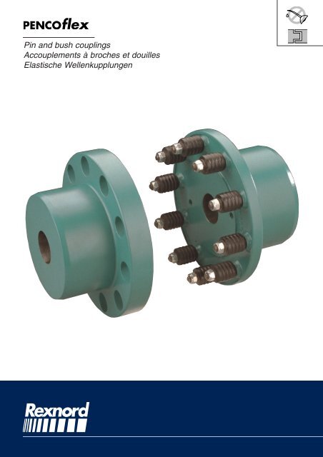
Pin and bush couplings<br />
Accouplements à broches et douilles<br />
Elastische Wellenkupplungen
<strong>89201efd271f</strong><br />
Rexnord S.A. - PTP Operation<br />
Elastomer Fail Safe Coupling<br />
Accouplement Positif à Élastomère<br />
Elastische Wellenkupplung<br />
Elastomer Coupling<br />
Accouplement à Élastomère<br />
Elastische Wellenkupplung<br />
Pin and Bush Couplings<br />
Accouplements à Broches et Douilles<br />
Elastische Wellenkupplung<br />
Super Elastomer Coupling<br />
Accouplement Superélastique<br />
Superelastische Wellenkupplung<br />
Hydrodynamic Coupling<br />
Coupleur Hydrodynamique<br />
Hydrodynamische Kupplung<br />
Mechanical Variators<br />
Variateurs Mécaniques<br />
Mechanische Variatoren<br />
®<br />
Magic-Grip-T ®<br />
Flotax<br />
Variable Speed Drives<br />
Variateurs de Vitesse<br />
Regelantriebe<br />
V-Belt Drives<br />
Gamme de Transmissions<br />
Keilriemenantriebe<br />
Shaft Mounted Gear Units with Torque Arm<br />
Réducteurs de Vitesse Pendulaires<br />
Schwenkaufsteckgetriebe<br />
Services<br />
2<br />
Technical Assistance<br />
Assistance Technique<br />
Technischer Unterstützung<br />
Cast Iron Foundry<br />
Fonderie de Fonte<br />
Giesserei<br />
Special Pulleys<br />
Poulies Spéciales<br />
Spezial Keilscheiben
<strong>89201efd271f</strong><br />
Contents<br />
Index<br />
Inhaltsverzeichnis<br />
Reference chart 4<br />
Tableau de référence 4<br />
Tabellarische Übersicht 4<br />
Selection procedure 5<br />
Méthode de sélection 5<br />
Auswahl Method 5<br />
Service factors 6<br />
Facteurs de service 6<br />
Betriebsfaktoren 6<br />
Selection - Applications 7<br />
Selection - Applications 7<br />
Auswahl - Anwendungen 7<br />
Notes 8<br />
Notes 8<br />
Notizen 8<br />
Selection - IEC Motor 9<br />
Selection - Moteur CEI 9<br />
Auswahl - IEC Motoren 9<br />
Description 10 - 11<br />
Description 10 - 11<br />
Beschreibung 10 - 11<br />
Coding 12<br />
Codification 12<br />
Bezeichnung 12<br />
Dimensional drawings 13 - 15<br />
Pins and bushes 16<br />
Balancing 17<br />
Mounting / Disassembly 18 - 19<br />
Alignment 19 - 21<br />
Maintenance 22<br />
Responsibility 23<br />
Plans d’encombrement 13 - 15<br />
Broches et douilles 16<br />
Équilibrage 17<br />
Montage / Démontage 18 - 19<br />
Alignement 19 - 21<br />
Maintenance 22<br />
Responsabilité23<br />
Maßzeichnungen 13 - 15<br />
Bolzen und Hülsen 16<br />
Auswuchtung 17<br />
Einbau / Ausbau 18 - 19<br />
Ausrichtung 19 - 21<br />
Wartung 22<br />
Haftung 23<br />
3
<strong>89201efd271f</strong><br />
Reference chart Tableau de référence Tabellarische Übersicht<br />
FEATURES<br />
CARACTÉRISTIQUES<br />
MERKMALE<br />
;;;;;;<br />
;;;;;;;<br />
;;;;;;;<br />
;;;;;<br />
;;;; ;;;<br />
;;;;;;<br />
;;;;;;;;<br />
;;;;;;;<br />
;;;;<br />
;;<br />
;;<br />
;;;;<br />
;;;;;;<br />
;;;;;;;<br />
;;;;;<br />
;;;<br />
;;;<br />
;;;;;;<br />
;;;;;;;<br />
;;;;;;;<br />
;;;;;<br />
;;<br />
T N (kNm)<br />
1 000<br />
100<br />
10<br />
Nominal torque<br />
Couple nominal<br />
Nenndrehmoment<br />
1<br />
0,1<br />
E<br />
∆E axial<br />
*** * ** *** **<br />
0%<br />
∆r radial<br />
*** * *** ** ***<br />
0%<br />
α angular<br />
α angulaire<br />
α winklig<br />
* * *** ** **<br />
0°<br />
T N<br />
Torsional<br />
elasticity at<br />
15°<br />
Elasticité<br />
EDPM & PROCOUPLAN<br />
torsionnelle 2° 5° 3° 0° 0°<br />
sous T N<br />
7° HYTREL<br />
Drehelastizität<br />
unter T N<br />
Ambient - 55°C<br />
temperature<br />
range +100°C - 40°C - 55°C - 30°C - 30°C - 40°C - 20°C<br />
Température<br />
ambiante<br />
Zulässige<br />
Umgebungstemperatur<br />
EDPM & PROCOUPLAN<br />
- 55°C<br />
+120°C<br />
HYTREL<br />
+90°C + 100°C + 80°C + 90°C + 150°C + 40°C<br />
Adaptability<br />
to chemical<br />
environment<br />
Adaptabilité aux<br />
environnements<br />
chimiques<br />
•<br />
Einsetzbar in<br />
chemisch<br />
agressiver<br />
Umgebung<br />
•<br />
Magic-Lock<br />
taper bushes<br />
Douilles<br />
Magic-Lock<br />
•<br />
Magic-Lock<br />
Spannbuchsen<br />
•<br />
Remarks :<br />
Remarques :<br />
Bemerkungen :<br />
4<br />
*** : Excellent / ** : Good / * : Average<br />
*** : Excellent / ** : Bien / * : Moyen<br />
*** : Excellent / ** : Gut / * : Mittelmäßig
<strong>89201efd271f</strong><br />
Selection procedure<br />
Méthode de sélection<br />
Auswahl Method<br />
1/Choice of coupling type :<br />
The choice is based on the type of<br />
application and the operating<br />
conditions.<br />
The reference chart on page 4 can help<br />
with the choice of coupling type.<br />
(Note : only use couplings with positive<br />
engagement for lifting motion !)<br />
1/Choix du type d’accouplement :<br />
Celui-ci est déterminé par le genre<br />
d’application et par les conditions de<br />
fonctionnement.<br />
Le tableau synthétique de la page<br />
4 peut aider à ce choix.<br />
(Remarque : employer uniquement un<br />
accouplement assurant une liaison positive<br />
sûre pour un mouvement de levage !)<br />
1/Auswahl des Kupplungstyps :<br />
Dieser ist abhängig von der<br />
Anwendungs-art und von den<br />
Betriebsumständen.<br />
Die tabellarische Übersicht auf Seite 4<br />
kann bei dieser Auswahl helfen.<br />
(Anmerkung : Verwenden Sie für<br />
Hebebewegungen nur<br />
durchschlagsichere Kupplungen !)<br />
Ta =<br />
2/Calculation of the nominal torque<br />
Ta (Nm) of the driven machine<br />
9550 x Pa<br />
n<br />
2/Calcul du couple nominal Ta (Nm)<br />
de la machine<br />
2/Bestimmung des effektiven<br />
Nenndrehmomentes Ta (Nm) der<br />
Arbeitsmaschine<br />
where : Pa = absorbed torque (kW)<br />
of the driven machine,<br />
n = speed (min -1 )<br />
où : Pa = puissance absorbée (kW)<br />
par la machine,<br />
n = vitesse (min -1 ).<br />
worin : Pa = Effektivleistung (kW)<br />
der Arbeitsmaschine,<br />
n = Drehzahl (min -1 ).<br />
3/Service factor determination SF<br />
See table in each catalogue.<br />
Service factor adders should be used if :<br />
• the driven machine is an internal<br />
combustion engine where torque<br />
fluctuations of more than 20 % may<br />
occur (see page 4),<br />
• the operating speed approaches the<br />
critical speed (consult us),<br />
• the ambient temperature exceeds<br />
60°C (consult us).<br />
• the number of starts per hour is more<br />
than 10 (consult factory).<br />
Should you be in any doubt please<br />
contact the factory for selection.<br />
3/Choix du facteur de service SF<br />
Voir tableau dans chaque catalogue.<br />
Des facteurs de service<br />
complémentaires doivent être<br />
appliqués lorsque :<br />
• la machine motrice est un moteur à<br />
combustion interne pouvant<br />
occasionner des variations de couple<br />
de plus de 20 % (voir page 4),<br />
• la vitesse de régime se rapproche<br />
sensiblement de la vitesse critique<br />
(nous consulter),<br />
• la température ambiante dépasse<br />
60°C (nous consulter).<br />
• le nombre de démarrages par heure<br />
est supérieur à 10 (nous consulter).<br />
En cas de doute, prière de nous consulter.<br />
3/Bestimmung des erforderlichen<br />
Betriebsfaktors SF<br />
Siehe Tabelle in jedes Katalog.<br />
Ein größerer Betriebsfaktor ist zu<br />
wählen wenn :<br />
• die Kraftmaschine ein Verbrennungsmotor<br />
ist, wobei Drehmomentschwankungen<br />
von über 20 % auftreten<br />
können (siehe seite 4),<br />
• die Betriebsdrehzahl in der Nähe der<br />
kritischen Drehzahl liegt (Rückfragen),<br />
• die Umgebungstemperatur 60°C<br />
überschreitet (Rückfragen).<br />
• bei mehr als 10 Anläufen pro Stunde<br />
(Rückfragen).<br />
In Zweifelsfällen bitten wir Sie uns bei<br />
der Auslegung zu Rate zu ziehen.<br />
4/Calculation of the equivalent<br />
torque Teq (Nm)<br />
4/Calcul du couple équivalent Teq (Nm)<br />
4/Berechnung des<br />
Äquivalentdrehmomentes Teq (Nm)<br />
Teq = Ta x SF<br />
where :Ta = torque (Nm)<br />
of the driven machine,<br />
SF = service factor<br />
où : Ta = couple (Nm)<br />
de la machine entraînée,<br />
SF = facteur de service<br />
worin : Ta = Drehmoment (Nm)<br />
der Arbeitsmaschine,<br />
SF = Betriebsfaktor<br />
5/Select the coupling size so that :<br />
T N ≥ Teq<br />
5/Sélection de la taille de<br />
l’accouplement, de manière que :<br />
5/Bestimmung der Baugröße :<br />
where :T N = nominal torque of the<br />
coupling (see<br />
dimensional drawings).<br />
où : T N = couple nominal de l’accouplement<br />
(voir plans d’encombrements).<br />
worin : T N = Nenndrehmoment der<br />
Kupplung (siehe<br />
Maßzeichnungen).<br />
6/Checking of the selection<br />
The maximal peak torque :<br />
6/Vérification de la sélection<br />
Couple de pointe maximum :<br />
6/Überprüfung der Auswahl :<br />
Maximales Spitzendrehmoment :<br />
Tmax ≤ 2 x T N<br />
7/Checking of the bores<br />
Check when the shaft diameters are<br />
known, whether the corresponding<br />
bores are available.<br />
If the coupling is to be bored and<br />
keywayed, please specify the correct<br />
dimensions and tolerances.<br />
7/Contrôle des alésages<br />
Les diamètres des bouts d’arbre étant<br />
connus, contrôler que les alésages<br />
correspondants peuvent être réalisés.<br />
Si les accouplements doivent être<br />
fournis alésés et rainurés, il y a lieu<br />
d’indiquer les cotes exactes et les<br />
tolérances désirées.<br />
7/Überprüfung der Bohrungen<br />
Überprüfen Sie, sobald die<br />
Wellendurchmesser bekannt sind, ob<br />
die entsprechenden Bohrungen<br />
ausgeführt werden können.<br />
Soll die Kupplung gebohrt und genutet<br />
sein, so sind die gewünschten Maße<br />
und Passungen genau anzugeben.<br />
5
<strong>89201efd271f</strong><br />
Service factors Facteurs de service Betriebsfaktoren<br />
For applications not listed :<br />
consult factory<br />
* : Consult factory<br />
Autres applications non mentionnées :<br />
nous consulter<br />
* : Nous consulter<br />
Für andere Anwendungen :<br />
Rückfrage erbeten<br />
* : Rückfrage<br />
Intern. comb. motor - 4 cylinders or more<br />
Intern. comb. motor - 1 to 3 cylinders<br />
Moteur thermique 4 cylindres et plus<br />
Moteur thermique 1 à 3 cylindres<br />
Verbrennungsmotor - 4 Zylinder oder mehr<br />
Verbrennungsmotor - 1 bis 3 Zylinder<br />
+ 0,25<br />
+ 0,75<br />
SERVICE FACTORS<br />
Applications<br />
AGITATORS<br />
Liquid with constant density<br />
Liquid with variable density<br />
Liquid with solid material<br />
FOOD INDUSTRY<br />
Meat grinders, mixers, Beet slicers<br />
Filling machines<br />
BREWING - DISTILLING<br />
Mash tubs<br />
Bottling machinery<br />
MILLS<br />
Ball,rod, plain & wedge bar<br />
Tumbling barrels<br />
RUBBER & PLASTIC INDUSTRY<br />
Strainers<br />
Rubber calenders, rubber mills<br />
Mixing mills<br />
CEMENT INDUSTRY<br />
Kilns, dryers & coolers<br />
COMPRESSORS<br />
Centrifugal<br />
Lobe, rotary<br />
Reciprocating :<br />
- multi-cylinders<br />
- single-cylinder<br />
SCREENS<br />
Rotary (stone & gravel)<br />
Travelling water intake<br />
DREDGES<br />
Cable reels, screen drives<br />
Cutter head drives<br />
Winches<br />
ELEVATORS<br />
Bucket<br />
Escalators<br />
Freight<br />
SEWAGE DISPOSAL EQUIPMENT<br />
Aerators<br />
Thickeners<br />
Dewatering screws, vaccum filters<br />
Mixers<br />
Bar screens, collectors<br />
GENERATORS (Not welding)<br />
CRANES & HOISTS<br />
Reversing, travel & trolley motion<br />
Main hoists :<br />
- medium duty<br />
- heavy duty<br />
MACHINE TOOLS<br />
Bending, rolls, plat planers & punch presses<br />
Main drives<br />
Feed drives<br />
MIXERS<br />
Constant density<br />
Variable density<br />
METAL MILLS<br />
Draw benches<br />
Wire winding machines<br />
Rolling Mill non reversing - group drives<br />
- group drives<br />
- individual drives<br />
OIL INDUSTRY<br />
Parafin filter presses<br />
Rotary kilns<br />
PUMPS<br />
Centrifugal<br />
Gear type, lobe, vane<br />
Single & double acting :<br />
- multi-cylinders<br />
- single-cylinder<br />
Screw pumps<br />
SAWING MACHINES<br />
Continuous<br />
TEXTILE INDUSTRY<br />
CONVEYORS<br />
Uniformly loaded or fed<br />
Heavy duty<br />
Reciprocating, shaker<br />
FANS<br />
Centrifugal<br />
Industrial<br />
Mine, etc...<br />
FACTEURS DE SERVICE<br />
Applications<br />
AGITATION<br />
Liquide à densité constante<br />
Liquide à densité variable<br />
Liquide avec matière solide<br />
ALIMENTAIRE<br />
Hachoirs à viande, moulins, pétrins<br />
Emboiteuse<br />
BRASSERIE - DISTILLERIE<br />
Broyeurs<br />
Machines à embouteiller<br />
BROYEURS<br />
A barres, à boulets<br />
A galets, à marteaux<br />
CAOUTCHOUC & MATIÈRES PLASTIQUES<br />
Boudineuses<br />
Calandres, laminoirs<br />
Mélangeurs<br />
CIMENTERIE<br />
Fours, tambours sécheurs<br />
COMPRESSEURS<br />
Centrifuges<br />
Rotatifs<br />
A pistons :<br />
- multicylindres<br />
- monocylindre<br />
CRIBLES<br />
Rotatifs (pierre & gravier)<br />
A circulation d’eau<br />
DRAGAGE<br />
Tambours enrouleurs de câbles<br />
Excavatrices<br />
Treuils divers<br />
ÉLÉVATEURS<br />
A godets<br />
Escaliers roulants<br />
Monte charge<br />
ÉPURATION<br />
Aérateurs<br />
Epaississeurs<br />
Pompes à vis, filtres à vide<br />
Mélangeurs<br />
Grilles, collecteurs<br />
GÉNÉRATRICES<br />
LEVAGE<br />
Translation, giration, direction<br />
Treuils :<br />
- service normal<br />
- service dur<br />
MACHINES OUTILS<br />
Machines à planer, plieuse, poinçonneuse<br />
Commandes principales<br />
Commandes auxiliaires<br />
MÉLANGEURS<br />
Densité constante<br />
Densité variable<br />
MÉTALLURGIE<br />
Bancs à tréfiler<br />
Enrouleuses<br />
Trains de rouleaux non réversibles - Commande<br />
multiple<br />
- Commande individuelle<br />
PÉTROLE<br />
Filtres-presses pour parafine<br />
Fours rotatifs<br />
POMPES<br />
Centrifuges<br />
A engrenages, à palettes<br />
A pistons :<br />
- multicylindres<br />
- monocylindre<br />
A vis<br />
SCIES<br />
A mouvement continu<br />
TEXTILE<br />
TRANSPORTEURS<br />
Service normal<br />
Service dur<br />
A secousse, tapis vibrants<br />
VENTILATEURS<br />
Centrifuges<br />
Industriels<br />
Pour mines, etc...<br />
BETRIEBSFAKTOREN<br />
Anwendungen<br />
RÜHRWERKE<br />
Flüßigkeit mit konstanter Dichte<br />
Flüßigkeit mit veränderlicher Dichte<br />
Flüßigkeit mit festen Körpern gemischt<br />
NÄHRMITTELINDUSTRIE<br />
Rübenschneidemaschinen, Fleischmühlen,<br />
Knetmaschinen, Zuckerrohrbrecher<br />
Füllmaschinen<br />
BRAUEREIEN - BRENNEREIEN<br />
Mühlen<br />
Flaschenfüllmaschinen<br />
MÜHLEN<br />
Kugelmühlen<br />
Hammermühlen, Schleudermühlen<br />
GUMMI- & KUNSTSTOFFINDUSTRIE<br />
Strangpressen<br />
Gummi-Kalander & -Walzwerke<br />
Mischer<br />
ZEMENTFABRIKEN<br />
Öfen, Trockentrommeln<br />
KOMPRESSOREN<br />
Kreiselkompressoren<br />
Rotationskompressoren<br />
Kolbenkompressoren :<br />
- Mehrzylinder<br />
- Einzylinder<br />
SIEBE<br />
Siebtrommeln (Stein & Kies)<br />
Siebe mit Wasserumlauf<br />
BAGGERWERKE<br />
Siebe, Kabelwinden<br />
Cutter-Antrieb<br />
Verschiedene Winden<br />
ELEVATOREN<br />
Becherwerke<br />
Rolltreppen<br />
Lastaufzüge<br />
WASSERKLÄRANLAGEN<br />
Belüfter<br />
Eindicker<br />
Schneckenpumpen, Vakuum-Filterpressen<br />
Mischer<br />
Rechen, Kanäle<br />
GENERATOREN<br />
HEBEZEUGE<br />
Fahrbewegung, Drehbewegung, Längs- und Katzfahrantrieb<br />
Winden ( Hubbewegung ) :<br />
- normaler Betrieb<br />
- schwerer Betrieb<br />
WERKZEUGMASCHINEN<br />
Richtwalzen, Stanzen, Biegemaschinen<br />
Hauptantriebe<br />
Hilfsantriebe<br />
MISCHER<br />
Konstante Dichte<br />
Veränderliche Dichte<br />
METALLINDUSTRIE<br />
Drahtziehbänke<br />
Aufwickeltrommeln<br />
Rollengänge, nicht umkehrbar<br />
- Mehrtrieb<br />
- Einzeltrieb<br />
ÖLINDUSTRIE<br />
Filter-Pressen für Paraffin<br />
Drehöfen<br />
PUMPEN<br />
Kreiselpumpen<br />
Zahnrad- und Flügelpumpen<br />
Kolbenpumpen :<br />
- Mehrzylinder<br />
- Einzylinder<br />
Schraubenpumpen<br />
SÄGEMASCHINEN<br />
Mit kontinuierlicher Bewegung<br />
TEXTILINDUSTRIE<br />
FÖRDERANLAGEN<br />
Normaler Betrieb<br />
Schwerer Betrieb<br />
Schüttelrutschen<br />
VENTILATOREN<br />
Zentrifugalventilatoren<br />
Industrieventilatoren<br />
Für Bergwerke, usw...<br />
Hours<br />
per day<br />
3h/24h<br />
0,9<br />
1<br />
1,25<br />
1,25<br />
0,8<br />
0,9<br />
0,8<br />
1,25<br />
1,5<br />
0,9<br />
1,25<br />
1,5<br />
1,25<br />
0,8<br />
0,9<br />
1,5<br />
2<br />
1<br />
0,8<br />
1,25<br />
1,5<br />
1<br />
1<br />
0,8<br />
1,25<br />
1,25<br />
0,9<br />
0,9<br />
0,9<br />
0,8<br />
0,8<br />
*<br />
1<br />
1,25<br />
1,25<br />
1<br />
0,9<br />
0,9<br />
1<br />
1,25<br />
1<br />
1,25<br />
1,5<br />
1<br />
1,25<br />
0,8<br />
0,9<br />
1<br />
*<br />
1<br />
0,9<br />
1<br />
0,9<br />
1<br />
2<br />
0,8<br />
0,9<br />
1,25<br />
Heures<br />
par jour<br />
10h/24h<br />
1<br />
1,25<br />
1,5<br />
1,5<br />
0,9<br />
1<br />
0,9<br />
1,5<br />
1,75<br />
1<br />
1,5<br />
1,75<br />
1,5<br />
0,9<br />
1<br />
1,75<br />
2,25<br />
1,25<br />
0,9<br />
1,5<br />
1,75<br />
1,25<br />
1,25<br />
0,9<br />
1,5<br />
1,5<br />
1<br />
1<br />
1<br />
0,9<br />
0,9<br />
*<br />
1,25<br />
1,5<br />
1,5<br />
1,25<br />
1<br />
1<br />
1,25<br />
1,5<br />
1,25<br />
1,5<br />
1,75<br />
1,25<br />
1,5<br />
0,9<br />
1<br />
1,25<br />
*<br />
1,25<br />
1<br />
1,25<br />
1<br />
1,25<br />
2,25<br />
0,9<br />
1<br />
1,5<br />
Stunden<br />
pro Tag<br />
24h/24h<br />
1,25<br />
1,5<br />
1,75<br />
1,75<br />
1<br />
1,25<br />
1<br />
1,75<br />
2<br />
1,25<br />
1,75<br />
2<br />
1,75<br />
1<br />
1,25<br />
2<br />
2,5<br />
1,5<br />
1<br />
1,75<br />
2<br />
1,5<br />
1,5<br />
1<br />
1,75<br />
1,75<br />
1,25<br />
1,25<br />
1,25<br />
1<br />
1<br />
*<br />
1,5<br />
1,75<br />
1,75<br />
1,5<br />
1,25<br />
1,25<br />
1,5<br />
1,75<br />
1,5<br />
1,75<br />
2<br />
1,5<br />
1,75<br />
1<br />
1,25<br />
1,5<br />
*<br />
1,5<br />
1,25<br />
1,5<br />
1,25<br />
1,5<br />
2,5<br />
1<br />
1,25<br />
1,75<br />
6
<strong>89201efd271f</strong><br />
Selection<br />
Applications<br />
Selection<br />
Applications<br />
Auswahl<br />
Anwendungen<br />
COUPLING TYPE - TYPE D’ACCOUPLEMENT - KUPPLUNGSTYP<br />
H<br />
H<br />
H<br />
H<br />
H<br />
L<br />
L<br />
L<br />
L<br />
L<br />
L<br />
L<br />
H<br />
H<br />
H<br />
H<br />
H<br />
H<br />
H<br />
H / L<br />
L<br />
L<br />
L<br />
L<br />
L<br />
H<br />
H<br />
H : High speed shafts<br />
L : Low speed shafts<br />
H : Arbres grande<br />
vitesse<br />
L : Arbres petite<br />
vitesse<br />
H : Schnelldreh. Wellen<br />
L : Langsamdreh.<br />
Wellen<br />
H<br />
H<br />
H<br />
L<br />
L<br />
L<br />
H<br />
H<br />
H<br />
L<br />
H<br />
L<br />
H<br />
H<br />
L<br />
H<br />
H / L<br />
H / L<br />
H / L<br />
H / L<br />
H / L<br />
H / L<br />
H / L<br />
H / L<br />
H / L<br />
H / L<br />
H / L<br />
L<br />
L<br />
L<br />
L<br />
H<br />
H<br />
H<br />
L<br />
L<br />
L<br />
L<br />
L<br />
H<br />
H<br />
H<br />
H<br />
H<br />
H<br />
H<br />
H<br />
H<br />
H<br />
H<br />
H / L<br />
L<br />
L<br />
L<br />
L<br />
L<br />
H / L<br />
H<br />
H<br />
H<br />
H<br />
H<br />
H / L<br />
H / L<br />
H / L<br />
L<br />
L<br />
L<br />
H<br />
H / L<br />
L<br />
L<br />
H<br />
H<br />
H / L<br />
H / L<br />
H<br />
H<br />
L<br />
L<br />
H<br />
H<br />
L<br />
L<br />
H / L<br />
H / L<br />
H / L<br />
H / L<br />
H<br />
H<br />
L<br />
L<br />
H<br />
H<br />
L<br />
L<br />
H / L<br />
H / L<br />
H / L<br />
H / L<br />
H / L<br />
H / L<br />
H / L<br />
H / L<br />
H / L<br />
H / L<br />
H / L<br />
H / L<br />
H / L<br />
H / L<br />
H / L<br />
H / L<br />
H / L<br />
H / L<br />
H / L<br />
H / L<br />
H / L<br />
H / L<br />
H / L<br />
H / L<br />
L<br />
L<br />
L<br />
H<br />
H<br />
H<br />
L<br />
L<br />
L<br />
H<br />
H<br />
H / L<br />
H / L<br />
H / L<br />
H / L<br />
H / L<br />
H / L<br />
H / L<br />
H / L<br />
H<br />
H<br />
H<br />
SURE-flex ® is a trade mark registred by T.B.Wood’s & Sons Company Chambersburg, PA. (U.S.A.)<br />
7
<strong>89201efd271f</strong><br />
Notes Notes Notizen<br />
8
<strong>89201efd271f</strong><br />
Selection<br />
IEC Motor<br />
Selection<br />
Moteur CEI<br />
Auswahl<br />
IEC Motoren<br />
Ød<br />
l<br />
h<br />
Remarks :<br />
This selection applies<br />
to the most common<br />
loads (SF min ≈ 1,4),<br />
10 to 24 hours of<br />
operation per day,<br />
maximum 10 starts,<br />
stops and/or overloads<br />
per hour.<br />
Motor shaft diameter :<br />
d ≤ 48 mm with<br />
tolerances to ISO k6,<br />
d ≥ 55 mm with<br />
tolerances to ISO m6.<br />
* Selection of the<br />
coupling is based on<br />
the maximum bore.<br />
Remarques :<br />
Cette méthode de<br />
sélection peut<br />
s’appliquer dans la<br />
plupart des cas<br />
(SF min ≈ 1,4), 10 à 24<br />
heures de service par<br />
jour, maximum 10<br />
démarrages, freinages<br />
et/ou surcharges par<br />
heure.<br />
Bouts d’arbre des<br />
moteurs :<br />
d ≤ 48 mm, tolérance<br />
ISO k6,<br />
d ≥ 55 mm, tolérance<br />
ISO m6.<br />
* Sélection de<br />
l’accouplement basée<br />
sur l’alésage<br />
maximum.<br />
Bemerkungen :<br />
Diese Auswahltabelle<br />
ist gültig für die<br />
meistvorkommenden<br />
Belastungsfälle<br />
(SF min ≈ 1,4), 10 bis<br />
24 Betriebs-stunden<br />
pro Tag, max. 10<br />
Anläufe, Bremsungen<br />
und/oder<br />
Überlastungs-stöße pro<br />
Stunde.<br />
Motorwellenzapfen :<br />
d ≤ 48 mm mit ISO<br />
Toleranzfeld k6,<br />
d ≥ 55 mm mit ISO<br />
Toleranzfeld m6.<br />
* Auswahl der Kupplung<br />
auf Basis der maximalen<br />
Bohrung.<br />
750 min -1<br />
1000 min -1<br />
1500 min -1<br />
h (mm) kW SURE-flex ® <strong>PENCOflex</strong> TEX-O-flex ECOflex HATECO HARCO Hydro-flow Ø d x l (mm)<br />
80 0,18 S4* P.145 BT4 TJ25 19 x 40<br />
0,25 S4* P.145 BT4 TJ25<br />
90S 0,37 S5* P.145 DE BT4 TJ25 24 x 50<br />
90L 0,55 S5* P.145 DE BT4 TJ25 24 x 50<br />
100L 0,75 S5* P.145 DE BT4 TA32* R0 H.250 28 x 60<br />
1,1 S5 P.145 DE BT4 TA32* R0 H.280<br />
112M 1,5 S5 P.145 DE BT4 TA32* R0 H.280 28 x 60<br />
1,85 S6 P.145 DE BT4 TA32* R0 H.320<br />
132S 2,2 S6 P.145 DE BT10* TJ38* R0 H.320 38 x 80<br />
132M 3 S6 P.145 DE BT10* TJ38* R0 H.350 38 x 80<br />
160M 4 S7 P.145 DE BT15* TA42* R0 H.400 42 x 110<br />
5,5 S8 P.145 DE BT15 TA42* R0 H.400<br />
160L 7,5 S8 P.145 DF BT15 TA42* R0 H.450 42 x 110<br />
180L 11 S9 P.145 DG BT22 TF55* R0 H.490 48 x 110<br />
200L 15 S10 P.155 DG BT30 TF55* R0 H.490 55 x 110<br />
225S 18,5 S10 P.155 DH BT40 TJ65* R0 H.490 60 x 140<br />
225M 22 S11 P.155 DH BT40 TJ65* R0 H.540 60 x 140<br />
250M 30 S11 P.175 DJ BT85* TA65* R1* H.540 65 x 140<br />
280S 37 S12 P.175 DJ BT85 TA80* R1* H.620 75 x 140<br />
280M 45 S12 P.200 DJ BT85 TA80* R1* H.620 75 x 140<br />
315S 55 S13 P.200 DK BT135 TA80* R2* H.620 80 x 170<br />
315M 75 S13 P.235 DL BT135 TA80* R2* H.680 80 x 170<br />
0,09 S3 BT4 TJ25 14 x 30<br />
71 0,12 S3 BT4 TJ25<br />
0,18 S3 BT4 TJ25<br />
0,25 S4* P.145 BT4 TJ25 H.190 19 x 40<br />
80 0,37 S4* P.145 BT4 TJ25 H.190<br />
0,55 S4 P.145 BT4 TJ25 H.190<br />
90S 0,75 S5* P.145 DE BT4 TJ25 H.250 24 x 50<br />
90L 1,1 S5 P.145 DE BT4 TJ25 H.250 24 x 50<br />
100L 1,5 S5 P.145 DE BT4 TA32* R0 H.250 28 x 60<br />
1,85 S5 P.145 DE BT4 TA32* R0 H.250<br />
112M 2,2 S6 P.145 DE BT4 TA32* R0 H.250 28 x 60<br />
132S 3 S6 P.145 DE BT10* TJ38* R0 H.280 38 x 80<br />
132M 4 S6 P.145 DE BT10* TJ38* R0 H.280 38 x 80<br />
5,5 S7 P.145 DE BT10 TJ38* R0 H.320<br />
160M 7,5 S8 P.145 DE BT15 TA42* R0 H.320 42 x 110<br />
160L 11 S9 P.145 DF BT15 TA42* R0 H.350 42 x 110<br />
180L 15 S9 P.145 DG BT22 TF55* R0 H.400 48 x 110<br />
200L 18,5 S10 P.145 DG BT30 TF55* R0 H.400 55 x 110<br />
22 S10 P.155 DG BT30 TF55* R0 H’450<br />
225M 30 S11 P.155 DH BT40 TJ65* R0 H.450 60 x 140<br />
250M 37 S11 P.175 DH BT85* TA65* R1* H.490 65 x 140<br />
280S 45 S12 P.175 DJ BT85 TA80* R1* H.490 75 x 140<br />
280M 55 S12 P.200 DJ BT85 TA80* R1* H.540 75 x 140<br />
315S 75 S13 P.200 DK BT135 TA80* R2* H.540 80 x 170<br />
315M 90 S13 P.235 DK BT135 TA80* R2* H.620 80 x 170<br />
56 0,06 S3 BT4 TJ25 9 x 20<br />
0,09 S3 BT4 TJ25<br />
63S 0,12 S3 BT4 TJ25 11 x 23<br />
0,18 S3 BT4 TJ25<br />
71 0,25 S3 BT4 TJ25 14 x 30<br />
0,37 S3 BT4 TJ25<br />
80 0,55 S4* P.145 BT4 TJ25 H.190 19 x 40<br />
0,75 S4* P.145 BT4 TJ25 H.190<br />
90S 1,1 S5* P.145 DE BT4 TJ25 H.190 24 x 50<br />
90L 1,5 S5* P.145 DE BT4 TJ25 H.190 24 x 50<br />
1,85 S5 P.145 DE BT4 TJ25 H.190<br />
100L 2,2 S5 P.145 DE BT4 TA32* R0 H.190 28 x 60<br />
3 S5 P.145 DE BT4 TA32* R0 H.250<br />
112M 4 S6 P.145 DE BT4 TA32* R0 H.250 28 x 60<br />
132S 5,5 S6 P.145 DE BT10* TJ38* R0 H.250 38 x 80<br />
132M 7,5 S7 P.145 DE BT10 TJ38* R0 H.250 38 x 80<br />
9 S7 P.145 DE BT10 TJ38* R0 H.280<br />
160M 11 S8 P.145 DE BT15 TA42* R0 H.280 42 x 110<br />
160L 15 S8 P.145 DF BT15 TA42* R0 H.280 42 x 110<br />
180M 18,5 S9 P.145 DF BT22 TF55* R0 H.320 48 x 110<br />
180L 22 S9 P.145 DG BT22 TF55* R0 H.320 48 x 110<br />
200L 30 S10 P.155 DG BT30 TF55* R0 H.350 55 x 110<br />
225S 37 S10 P.155 DH BT40 TJ65* R0 H.400 60 x 140<br />
225M 45 S11 P.155 DH BT40 TJ65* R0 H.400 60 x 140<br />
250M 55 S11 P.175 DH BT55* TA65* R1* H.400 65 x 140<br />
280S 75 S12 P.200 DJ BT85 TABO* R1* H.450 75 x 140<br />
280M 90 S12 P.200 DJ BT85 TABO* R1* H.450 75 x 140<br />
315S 110 S13 P.200 DK BT135 TABO* R2* H.490 80 x 170<br />
315M 132 S13 P.235 DK BT135 TABO* R2* H.490 80 x 170<br />
56 0,09 S3 BT4 TJ25 9 x 20<br />
0,12 S3 BT4 TJ25<br />
63S 0,18 S3 BT4 TJ25 11 x 23<br />
0,25 S3 BT4 TJ25<br />
71 0,37 S3 BT4 TJ25 14 x 30<br />
0,55 S3 BT4 TJ25<br />
80 0,75 S4* P.145 BT4 TJ25 H.190 19 x 40<br />
1,1 S4* P.145 BT4 TJ25 H.190<br />
SURE-flex ® is a trade<br />
90S 1,5 S5* P.145 DE BT4 TJ25 H.190 24 x 50<br />
mark registred by<br />
90L 1,85 S5* P.145 DE BT4 TJ25 H.190 24 x 50<br />
T.B.Wood’s & Sons<br />
2,2 S5* P.145 DE BT4 TJ25 H.190<br />
Company<br />
100L 3 S5* P.145 DE BT4 TA32* R0 H.190 28 x 60<br />
Chambersburg, PA.<br />
112M 4 S5* P.145 DE BT4 TA32* R0 H.190 28 x 60<br />
132S 5,5 S6* P.145 DE BT10* TJ38* R0 H.250* 38 x 80<br />
(U.S.A.)<br />
7,5 S6 P.145 DE BT10* TJ38* R0 H.250*<br />
132M 9 S6 P.145 DE BT10* TJ38* R0 H.250* 38 x 80<br />
160M 11 S7* P.145 DE BT15* TA42* R0 H.250* 42 x 110<br />
15 S7 P.145 DE BT15* TA42* R0 H.250*<br />
160L 18,5 S7 P.145 DE BT15* TA42* R0 H.250 42 x 110<br />
180M 22 S8 P.145 DE BT22* TF55* R0 H.280* 48 x 110<br />
200L 30 S8 P.145 DF BT30* TF55* R0 H.350* 55 x 110<br />
37 S9 P.145 DF BT30* TF55* R0 H.350*<br />
225M 45 S9 P.145 DG BT30* TJ65* R0 H.350* 55 x 110<br />
250M 55 S10 P.175* DH* BT85* TA65* R1* 60 x 140<br />
280S 75 S10 P.175* DJ* BT85* TABO* R1* 65 x 140<br />
280M 90 S11 P.175* DJ* BT85* TABO* R1* 65 x 140<br />
315S 110 S11 P.200* DJ* BT135* TABO* R2* 65 x 140<br />
9<br />
315M 132 S12 P.200* DJ BT135* TABO R2* 65 x 140<br />
9<br />
3000 min -1
<strong>89201efd271f</strong><br />
Description<br />
Description<br />
Beschreibung<br />
The <strong>PENCOflex</strong> coupling is made up of<br />
two (female and male) cast iron hubs<br />
onto which pins fitted with rubber<br />
bushes are mounted. The pins, made<br />
up of ground steel, have a cylindrical<br />
shape up to size 460. Pins of sizes 145<br />
to 200 are axially fastened by a circlips<br />
and a nut; those of sizes 235 to 460 by<br />
two circlips. Pins over size 510 are an<br />
internally- threaded and tapered, and<br />
are attached by a screw and washer.<br />
A circlips restricts the socket's<br />
translational motion.<br />
The rubber bushes are vulcanized onto<br />
wear-resisting brass liners which are<br />
mounted on the pins with a clearance.<br />
This allows them to rotate freely and<br />
move slightly lengthwise. The stress<br />
exerted onto the bearings is thus<br />
significantly reduced. A unique<br />
scalloped barrel shape of the bushes<br />
guarantees a uniform distribution of<br />
loads, even in case of misalignment,<br />
thus limiting the bending moment<br />
resulting from the radial force on the<br />
pins. This ensures increased durability<br />
of both bushes and pins.<br />
L'accouplement <strong>PENCOflex</strong> se<br />
compose d'un plateau femelle et d'un<br />
plateau mâle sur lequel sont montées<br />
des broches munies de douilles en<br />
caoutchouc. Les deux plateaux sont en<br />
fonte. Les broches, en acier rectifié,<br />
sont de forme cylindrique jusqu'à la<br />
taille 460. Leur fixation axiale est<br />
assurée par un circlips et un écrou<br />
pour les tailles 145 à 200 et par deux<br />
circlips pour les tailles 235 à 460.<br />
A partir de la taille 510, les broches ont<br />
une extrémité conique taraudée et sont<br />
fixées à l'aide d'une vis et d'une<br />
rondelle. Un circlips retient la douille en<br />
translation.<br />
Les douilles en caoutchouc sont<br />
vulcanisées sur des buselures en laiton<br />
résistant à l'usure. Ces buselures sont<br />
montées sur les broches avec un jeu<br />
permettant leur libre rotation ainsi<br />
qu'une petite translation. Ainsi la<br />
sollicitation des paliers est<br />
considérablement réduite. La forme<br />
particulière des douilles en tonnelet<br />
échancré assure une bonne répartition<br />
des efforts, même en cas de<br />
désalignement, limitant ainsi le moment<br />
de flexion dû à l'effort radial sur la<br />
broche. Il en résulte un accroissement<br />
de la durée de vie des douilles et des<br />
broches.<br />
Die <strong>PENCOflex</strong> Kupplung besteht aus<br />
einem Lochteil und einem Bolzenteil.<br />
Letzteres trägt die Übertragungsbolzen<br />
mit den darauf befestigten<br />
Gummihülsen. Loch- und Nabenteil sind<br />
aus Grauguß. Die Übertragungsbolzen,<br />
aus geschliffenem Stahl, sind<br />
zylindrisch bis zur Größe 460. Ihr axialer<br />
Sitz mit Verschiebespiel wird bei den<br />
Größen 145 bis 200 durch einen<br />
Sprengring und eine Mutter, bei den<br />
Größen 235 bis 460 durch zwei<br />
Sprengringe gesichert. Ab Größe 510<br />
haben die Bolzen einen Kegelsitz mit<br />
aussenseitigem Gewinde und werden<br />
mit Druckscheibe und Schraube<br />
gesichert. Ein Sprengring begrenzt den<br />
Axialsitz der Hülsen.<br />
Die Gummihülsen sind auf<br />
verschleißfeste Messingbuchsen<br />
aufvulkanisiert, welche auf den<br />
Übertragungsbolzen mit<br />
angemessenem Spiel, das ihnen freie<br />
Drehung und geringen axialen Weg<br />
gestattet, sitzen. Dies trägt zu einer<br />
beträchtlichen Reduzierung der<br />
Reaktionskräfte auf die Wellenlager bei,<br />
die infolge winkliger Ausrichtfehler oder<br />
axialer Verlagerungen auftreten können.<br />
Das besondere Konzept der<br />
tonnenförmigen und profilierten<br />
Gummihülsen garantiert selbst bei<br />
kleineren Ausrichtfehlern eine gute<br />
Belastungs-verteilung, da das durch<br />
radiale Lasten auf die Bolzen<br />
verursachte Biegemoment verringert<br />
wird. Es ergibt sich daraus auch eine<br />
bedeutend längere Lebensdauer der<br />
Gummihülsen und<br />
Übertragungsbolzen.<br />
10
<strong>89201efd271f</strong><br />
Description<br />
Description<br />
Beschreibung<br />
Dynamic behavior<br />
The combined elasticity and damping<br />
capacity of the rubber bushes reduces<br />
both shock loads and critical velocity.<br />
Compressed by an increasing torque,<br />
the bushes become stiffer due to the<br />
scalloping, thereby reducing the<br />
resonance effect at critical velocities.<br />
Arrangement PB : with brake drum<br />
This version is made up of two parts:<br />
- the standard female hub,<br />
- a male hub fitted with a brake drum.<br />
Arrangement PD : with brake disc<br />
This version is made up of four parts:<br />
- the standard female hub,<br />
- an intermediate part,<br />
- a brake hub,<br />
- a webbed brake disc mounted<br />
between the latter two parts (ventilated<br />
brake disk also available).<br />
Comportement dynamique<br />
L'élasticité et le pouvoir amortisseur des<br />
douilles en caoutchouc permettent<br />
d'absorber des à-coups et d'abaisser la<br />
vitesse critique.<br />
Sollicitées par un couple croissant, les<br />
douilles deviennent progressivement<br />
plus raides grâce aux échancrures<br />
réduisant ainsi l'effet de résonnance<br />
aux vitesses critiques.<br />
Exécution PB : avec tambour de frein<br />
Cette exécution comporte deux parties :<br />
- le plateau femelle standard,<br />
- un plateau mâle équipé d'un tambour<br />
de frein.<br />
Exécution PD : avec disque de frein<br />
Cette exécution comporte quatre<br />
parties :<br />
- le plateau femelle standard,<br />
- une pièce intermédiaire,<br />
- un moyeu,<br />
- un disque plein, pincé entre les deux<br />
précédentes pièces. (Disque ventilé sur<br />
demande).<br />
Dynamisches Verhalten<br />
Durch die Elastizität und das Dämpfungsvermögen<br />
der Gummihülsen wird die<br />
Aufnahme von Stößen und eine Senkung<br />
der kritischen Drehzahl ermöglicht.<br />
Bei Beanspruchung durch steigendes<br />
Drehmoment werden die Gummihülsen<br />
dank ihrer profilierten Tonnenform<br />
zunehmend steifer, so daß<br />
Resonanzeffekte bei kritischen<br />
Drehzahlen verringert werden.<br />
Ausführung PB : mit Bremstrommel<br />
Bei dieser Ausführung kommen zwei<br />
Teile zur Verwendung :<br />
- das Lochteil der Normalausführung,<br />
- ein als Bremstrommel ausgebildetes<br />
Bolzenteil.<br />
Ausführung PD : mit Bremsscheibe<br />
Bei dieser Ausführung kommen vier<br />
Teile zur Verwendung :<br />
- das Lochteil der Normalausführung,<br />
- ein die Bolzen tragendes Zwischenteil,<br />
- ein Nabenteil,<br />
- eine volle Bremsscheibe aus Stahl,<br />
zwischen den zweivorgenannten Teilen<br />
klemmend verschraubt. (Belüftete<br />
Bremsscheibe auf Wunsch lieferbar)<br />
It is up to the customer to check that<br />
the correct size of brake drum or disk is<br />
used. Rexnord cannot be held<br />
responsible for incorrect selection of<br />
brake system.<br />
Il appartient au client de s'assurer du<br />
bon dimensionnement du tambour ou<br />
du disque de frein. Rexnord ne saurait<br />
être tenu pour responsable en cas de<br />
mauvaise sélection des appareils de<br />
freinage<br />
Es liegt am Kunden die richtige<br />
Bremstrommel oder -scheibe zu<br />
auswählen. Rexnord kann nicht<br />
Verantwortlich gestellt werden bei<br />
falschem Bremssytemauswahl.<br />
11
<strong>89201efd271f</strong><br />
Coding Codification Bezeichnung<br />
P<br />
2 3<br />
4 5 6 7<br />
-<br />
2<br />
Arrangement<br />
N : normal arrangement<br />
B : with brake drum<br />
D : with brake disk<br />
Exécution<br />
N : exécution normale<br />
B : avec tambour de frein<br />
D : avec disque de frein<br />
Ausführung<br />
N : Normalausführung<br />
B : mit Bremstrommel<br />
D : mit Bremsscheibe<br />
3<br />
Size<br />
145 to 1420<br />
Taille<br />
145 à 1420<br />
Baugröße<br />
145 bis 1420<br />
4<br />
Male flange hub ➀<br />
-, L, S<br />
Moyeu du côté plateau mâle ➀<br />
-, L, S<br />
Nabe des Bolzenteiles ➀<br />
-, L, S<br />
5<br />
Femal flange hub ➁<br />
L, S<br />
Moyeu du côté plateau femelle ➁<br />
L, S<br />
Nabe des Lochteiles ➁<br />
L, S<br />
6<br />
Diameter of braking system<br />
Drum :<br />
Diamètre de l'organe de freinage<br />
Tambour :<br />
Durchmesser des Bremsorganes<br />
Trommel :<br />
200, 250, 315, 400, 500, 630, 710<br />
200, 250, 315, 400, 500, 630, 710<br />
200, 250, 315, 400, 500, 630, 710<br />
Disk :<br />
Disque :<br />
Scheibe :<br />
315, 355, 395, 445, 550, 625, 705, 795<br />
315, 355, 395, 445, 550, 625, 705, 795<br />
315, 355, 395, 445, 550, 625, 705, 795<br />
7<br />
Bores and keyways specifications<br />
Without specification, keyways as per<br />
ISO R773.<br />
Spécification d'alésage et de<br />
clavetage<br />
Sans spécification, clavetage selon ISO<br />
R773.<br />
Bohrungen und Paßfedernuten<br />
Hinweise<br />
Ohne Hinweis, Paßfedernut nach ISO<br />
R773.<br />
Example Exemple Beispiel<br />
P B 280 -<br />
L - 500 ø80 mm H7 / ø100 mm H7<br />
<strong>PENCOflex</strong> size 280 coupling with<br />
brake drum diameter 500 mm, femal<br />
flange hub L, bored to ø80 mm and<br />
ø100 mm H7 tolerance with standard<br />
keyways as per ISO R773.<br />
Accouplement <strong>PENCOflex</strong> taille 280,<br />
avec tambour de frein de diamètre<br />
500 mm, plateau femelle à moyeu L,<br />
alésages ø80 mm et ø100 mm<br />
tolérance H7 et clavetages normalisés<br />
suivant ISO R773.<br />
<strong>PENCOflex</strong> Kupplung mit Bremstrommel,<br />
Größe 280, Lochteilnabe L,<br />
Bremstrommel mit Durchmesser<br />
500 mm, fertiggebohrt ø80 mm und<br />
ø100 mm Toleranz H7 und Paßfederverbindung<br />
nach ISO R773.<br />
12
;<br />
;<br />
;; ;<br />
<strong>89201efd271f</strong><br />
P<br />
N<br />
Normal arrangement<br />
Exécution normale<br />
Normalausführung<br />
145 1420<br />
Size<br />
Taille<br />
Baugröße<br />
- / S / L<br />
Male flange hub ➀<br />
Moyeu côté plateau mâle ➀<br />
Nabe des Bolzenteiles ➀<br />
S / L<br />
Female flange hub ➁<br />
Moyeu côté plateau femelle ➁<br />
Nabe des Lochteiles ➁<br />
The user is responsible<br />
for the provision of<br />
safety guards and<br />
correct installation of all<br />
equipment.<br />
Certified dimensions<br />
available upon request.<br />
Les dispositifs de<br />
protection doivent être<br />
prévus par l'utilisateur.<br />
Celui-ci est responsable<br />
de l'installation correcte<br />
de l'ensemble.<br />
Dimensions définitives<br />
sur demande.<br />
;<br />
;<br />
;;;;;;;;;;;;<br />
;;;;;;;;;;;;<br />
;;;;;;;;;;;<br />
;<br />
;;;;;<br />
;;;;<br />
;<br />
;<br />
;;;;;;;;;;;;<br />
;;;;;;;;;;;;<br />
;;;;;;;;;;;;<br />
;;<br />
;;;<br />
;;;<br />
;;;<br />
;<br />
;;;;;;;;<br />
;;;;;;;;;<br />
;;;;;;;;;;<br />
;;;;;;;;;;<br />
;;;;;;;;;;<br />
;;;;;;;;;;<br />
;;;;;;;;;;<br />
;;<br />
;;; ;;<br />
;;; ;;;<br />
;; ;;;<br />
;;<br />
;;<br />
;;;<br />
;;;<br />
;;;<br />
;; ;;;<br />
;;; ;;;<br />
;;; ;;;<br />
;;; ;;;<br />
;;; ;;;<br />
;;; ;;;<br />
;;; ;;;<br />
;;; ;;;<br />
;;; ;;<br />
;;;<br />
;;;<br />
;;;<br />
;;<br />
;<br />
;<br />
Der Benutzer ist<br />
verantwortlich für die<br />
Beistellung der<br />
Schutzhauben und das<br />
fachgemäße Aufstellen<br />
der gesamten<br />
Ausrüstung.<br />
Verbindliche Maße auf<br />
Wunsch.<br />
;;;;<br />
;;;;;<br />
;;;;;<br />
;;;;;;<br />
;;;;;;<br />
;;;<br />
;;;;<br />
;<br />
;;; ;;;;;<br />
;;;;;;;<br />
;;;<br />
;<br />
;;<br />
;;<br />
;;;;<br />
;;; ;;; ;;;<br />
;;;;<br />
;;;; ;;;;<br />
;;;;;;<br />
;<br />
;;<br />
;;;<br />
;;; ;;;<br />
;;;<br />
;;;; ;;; ;;;<br />
;;;;;<br />
;;; ;;<br />
;<br />
PN145<br />
PN200<br />
;;;;<br />
;;;;<br />
;;;;<br />
;;;;<br />
;;;;<br />
;;;; ;;;;<br />
;;;; ;;;;<br />
;;;; ;;;;<br />
;;;; ;;;;<br />
;;;; ;;;;<br />
;;;; ;;;;<br />
;;;; ;;;;<br />
;;;; ;;;;<br />
;;; ;;;;<br />
;;;;<br />
;;;;<br />
;;;;<br />
;;;;<br />
;;;<br />
;;;;<br />
;;;;;<br />
;;;;<br />
;;;;;<br />
;;;;;;<br />
; ;;;;;<br />
;; ;;;;<br />
PN235<br />
PN460<br />
;;;;<br />
;;;;<br />
;;;;<br />
;;;;<br />
;;;;<br />
;;;; ;;;;<br />
;;;; ;;;;<br />
;;;; ;;;;<br />
;;;; ;;;;<br />
;;;; ;;;;<br />
;;;; ;;;;<br />
;;;; ;;;;<br />
;;;; ;;;;<br />
;;; ;;;;<br />
;;;;<br />
;;;;<br />
;;;;<br />
;;;;<br />
;;;<br />
;;;;<br />
;;;;;<br />
;;;;<br />
;<br />
;;;;;<br />
;;;;;;<br />
;;;;;;<br />
PN510<br />
PN1420<br />
;;<br />
;;;<br />
;;;;<br />
;;;;<br />
;;;;<br />
;;;;<br />
;;;;<br />
;;;;<br />
;;;;<br />
;;;<br />
;;;;<br />
;;;<br />
;;;;<br />
;;;<br />
;;;;<br />
;;;<br />
;;;;<br />
;;;<br />
;;;;<br />
;;;<br />
;;;<br />
;;;<br />
;;<br />
;;;<br />
;;;<br />
;;;<br />
;;;<br />
;;;<br />
;;;<br />
;;<br />
Remarks :<br />
Unless specified on the<br />
order draft, couplings<br />
are delivered without<br />
boring.<br />
(1) For speeds > nmax :<br />
consult factory.<br />
(2) Maximum bores for<br />
keyways as per ISO<br />
R773.<br />
(3) No chambering is<br />
provided when the<br />
shaft length in hub is<br />
smaller than 5/6 of the<br />
dimension L.<br />
(4) For minimum bore.<br />
Remarques :<br />
Sans indication à la<br />
commande, les<br />
accouplements sont<br />
livrés non alésés.<br />
(1) Pour des vitesses<br />
> nmax : nous consulter.<br />
(2) Alésages maximum<br />
pour rainures suivant<br />
ISO R773.<br />
(3) Le chambrage n’est<br />
pas prévu lorsque la<br />
portée de l’arbre est<br />
inférieure à 5/6 de la<br />
côte L.<br />
(4) Pour alésage<br />
minimum.<br />
Anmerkungen :<br />
Ohne entspr. Hinweis<br />
bei Bestellung werden<br />
die Kupplungen<br />
ungebohrt geliefert.<br />
(1) Für Drehzahlen ><br />
nmax : rückfragen.<br />
(2) Max.- Bohrungen bei<br />
Paßfederverbindungen<br />
gem. ISO R773.<br />
(3) Keine mitige<br />
Ausdrehung der<br />
Borhung wenn<br />
Wellenstumpf mit<br />
weniger als 5/6 von<br />
Maße in der Naße.<br />
(4) Gültig bei Min.<br />
Bohrungen.<br />
D1<br />
Size TN (Nm) n max D2 D1 D2 A B C L M1 M2 N1 N2 T R W J m<br />
Taille 9550 . kW min-1 min. max. max. kgm 2 kg<br />
Baugröße min -1 (1) (2) (2) (3) (4) (4)<br />
145LL 250 4 700 19 60 55 145 113,5 3,5 55 36 16,5 93 88 - 75 M8 0,016 8<br />
155LL 400 4 400 19 65 60 155 123,5 3,5 60 41 21,5 100 95 - 80 M8 0,021 9<br />
175LL 630 3 900 28 75 75 175 153,5 3,5 75 56 36,5 116 116 - 95 M10 0,04 14<br />
200LL 1 000 3 400 35 85 80 200 183,5 3,5 90 71 51,5 132 127 - 105 M10 0,071 21<br />
235LL 1 600 2 900 35 95 90 235 204 4 100 65 48 147 142 - 120 M12 0,175 34<br />
245LL 2 500 2 800 35 110 100 245 224 4 110 75 58 170 160 - 135 M12 0,235 42<br />
280LL 3 900 2 450 85 125 110 280 264 4 130 95 78 195 180 - 145 M12 0,43 56<br />
SS 35 85 85 155 155 0,34 50<br />
315LL 6 100 2 200 100 140 125 315 304 4 150 115 98 217 202 - 165 M12 0,72 76<br />
SS 45 100 100 180 180 0,59 71<br />
355LL 9 300 1 950 120 160 140 355 365,5 5,5 180 129 108 248 228 - 190 M16 1,53 119<br />
SS 75 120 120 210 210 1,33 119<br />
385LL 14 000 1 800 130 180 160 385 405,5 5,5 200 149 128 280 256 - 220 M16 2,41 161<br />
SS 85 130 130 230 230 1,95 150<br />
460LL 21 000 1 500 140 200 200 460 445,5 5,5 220 169 148 290 290 - 232 M20 4,35 220<br />
SS 95 160 160 250 250 3,65 210<br />
510LL 31 000 1 350 160 220 220 510 487 7 240 162 144 320 320 80 260 M20 8,5 315<br />
SS 110 180 180 280 280 7,6 310<br />
575LL 45 000 1 200 160 230 230 575 527 7 260 182 164 330 330 85 300 M24 12,9 410<br />
SS 125 190 190 290 290 11,8 385<br />
670LL 65 000 1 000 180 260 260 670 587 7 290 212 194 365 365 95 320 M24 23,5 560<br />
SS 140 210 210 325 325 21,5 540<br />
725LL 94 000 950 210 290 290 725 668,5 8,5 330 221 201 410 410 110 350 M24 43 830<br />
SS 160 240 240 370 370 41 810<br />
850LL 140 000 800 230 320 320 850 728,5 8,5 360 251 231 455 455 120 390 M30 80 1 140<br />
SS 180 260 260 405 405 75 1 110<br />
990LL 200 000 700 280 360 360 990 828,5 8,5 410 301 281 520 520 135 430 M30 148 1 590<br />
SS 200 310 310 480 480 141 1 640<br />
1060LL 285 000 650 320 400 400 1060 910,5 10,5 450 298 275 580 580 150 470 M30 260 2 250<br />
SS 230 350 350 540 540 250 2 380<br />
1220LL 410 000 550 360 440 440 1220 1010,5 10,5 500 348 325 640 640 165 515 M36 455 3 050<br />
SS 260 390 390 600 600 440 3 210<br />
1420LL 600 000 480 400 480 480 1420 1130,5 10,5 560 408 385 705 705 185 560 M36 820 4 200<br />
SS 300 430 430 665 665 800 4 350<br />
97C2PN0001-2<br />
mm<br />
13
;<br />
;<br />
;<br />
<strong>89201efd271f</strong><br />
P<br />
B<br />
With brake drum<br />
Avec tambour de frein<br />
Mit Bremstrommel<br />
155 460<br />
Size<br />
Taille<br />
Baugröße<br />
L/ S<br />
Female flange hub ➁<br />
Moyeu côté plateau femelle ➁<br />
Nabe des Lochteiles ➁<br />
200 710<br />
Diameter of the brake drum<br />
Diamètre du tambour de frein<br />
Bremstrommel Durchmesser<br />
The user is responsible<br />
for the provision of safety<br />
guards and correct<br />
installation of all<br />
equipment.<br />
Certified dimensions<br />
available upon request.<br />
Les dispositifs de<br />
protection doivent être<br />
prévus par l'utilisateur.<br />
Celui-ci est responsable<br />
de l'installation correcte<br />
de l'ensemble.<br />
Dimensions définitives<br />
sur demande.<br />
;;;;;;;;;;;;;;;;;;;<br />
;;;;;;;;;;;;;;;;;;;; ;<br />
;;;;;;;;;;;;;;;;;;;;<br />
;;;;;;;;;;;;;;;;;;;<br />
;;;;;;;;;;;;;;;;;;<br />
;;;;;;;;;<br />
;;;;;;;;;;<br />
;;;;;;;;;;<br />
;;;;;;;;;;<br />
;;;;;;;;;;<br />
;;;;;;;;;;<br />
;;;;;;;;;;<br />
;;;;;;;;;;<br />
;;;;;;;;;;<br />
;;;;;;;;;;<br />
;;;;;;;;;<br />
;;;;;;;;;;<br />
;;;;;;;;;;;<br />
;;;;;;;;;;;<br />
;;;;;;;;;;;<br />
;;<br />
;;;<br />
; ;; ;;;<br />
;;;<br />
;; ;<br />
;;;;;;;;<br />
;;;;;;;;;<br />
;;;;;;;;;<br />
;;;;;;;;;<br />
;;;;;;;;;<br />
;;;;;;;;<br />
;;;<br />
;<br />
;;;;<br />
;;;; ;;;<br />
;<br />
;;;; ;;;;<br />
;;<br />
;;<br />
;;;<br />
;;;;<br />
;;<br />
;;;<br />
;;;;<br />
;;;;<br />
;; ;;;;<br />
;;; ;;;;<br />
;;; ;;;;<br />
;;; ;;;;<br />
;;; ;;;;<br />
;;; ;;;;<br />
;;; ;;;<br />
;;;<br />
;;;<br />
;;;<br />
;;<br />
;; ;;;;;;;;;;;;;;;;;;;; ;; ;;;;;;;;;;;<br />
;;<br />
;<br />
;<br />
;;<br />
➁<br />
;<br />
;<br />
Der Benutzer ist<br />
verantwortlich für die<br />
Beistellung der<br />
Schutzhauben und das<br />
fachgemäße Aufstellen<br />
der gesamten Ausrüstung.<br />
Verbindliche Maße auf<br />
Wunsch.<br />
3<br />
PB155-200<br />
PB245-400<br />
PB355-L710<br />
PB200-315<br />
Remarks :<br />
Unless specified on the<br />
order draft, couplings are<br />
delivered without boring.<br />
Drum material :<br />
øA ≤ ø400 mm :<br />
EN-GJL-250<br />
øA > ø400 mm :<br />
EN-GJS-500-7<br />
(1) For speeds > nmax :<br />
consult factory.<br />
(2) Maximum bores for<br />
keyways as per ISO<br />
R773.<br />
(3) For maximum bore.<br />
Remarques :<br />
Sans indication à la<br />
commande, les<br />
accouplements sont<br />
livrés non alésés.<br />
Matière tambour :<br />
øA ≤ ø400 mm :<br />
EN-GJL-250<br />
øA > ø400 mm :<br />
EN-GJS-500-7<br />
(1) Pour des vitesses ><br />
nmax : nous consulter.<br />
(2) Alésages maximum<br />
pour rainures suivant<br />
ISO R773.<br />
(3) Pour alésage<br />
maximum.<br />
Size TN (Nm) n max D2 D2 D3 D3 A B E L2 L3 L7 M2 N2 N3<br />
Taille 9550 . kW min-1 min. max. min. max. min.<br />
Baugröße min -1 (1) (2) (2)<br />
155 - L200 400 3 400 19 60 19 60 200 183,5 3,5 60 120 72 21,5 95 95<br />
175 - L250 630 2 750 28 75 28 75 250 223,5 3,5 75 145 87 36,5 116 116<br />
200 - L315 1 000 2 200 35 80 28 80 315 248,5 3,5 90 155 93 51,5 127 127<br />
245 - L400 2 500 1 700 35 100 35 100 400 299 4 110 185 110 51 160 160<br />
280 -L 315 3 900 2 200 85 110 35 110 315 289 4 130 155 93 71 180 180<br />
-S 35 85 155<br />
280 -L 500 3 900 2 200 85 110 45 110 500 384 4 130 250 150 71 180 180<br />
-S 35 85 155<br />
315 -L 500 6 100 2 200 100 125 45 125 500 404 4 150 250 150 91 202 202<br />
-S 45 100 180<br />
315 -L 630 6 100 1 800 100 125 55 125 630 429 4 150 275 165 91 202 202<br />
-S 45 100 180<br />
315 -L 710 6 100 1 600 100 125 55 125 710 444 4 150 290 175 91 202 202<br />
-S 45 100 180<br />
355 -L 710 9 300 1 600 120 140 55 125 710 475,5 5,5 180 290 175 105 228 195<br />
-S 75 120 210<br />
385 -L 710 14 000 1 600 130 160 55 125 710 495,5 5,5 200 290 175 128 256 195<br />
-S 85 130 230<br />
460 -L 710 21 000 1 500 140 200 55 125 710 515,5 5,5 220 290 175 148 290 195<br />
-S 95 160 250<br />
;;;;;; ;<br />
;;;<br />
;;;;<br />
;;;;;<br />
;;;;<br />
;;;<br />
;;;;;<br />
; ; ;;<br />
;;;<br />
;;;<br />
;;<br />
;;<br />
; ; ;;<br />
;;;<br />
;;;<br />
;;<br />
;;<br />
;;;<br />
;;;<br />
;;;<br />
;;;<br />
;;<br />
;;;<br />
;;;<br />
;;;<br />
;;;<br />
;;<br />
;;;;;;<br />
PB315-S710<br />
;;<br />
;;;<br />
;;;<br />
;;;<br />
;;<br />
;;<br />
;;;;<br />
;;;;<br />
;;;;<br />
;;;<br />
;;<br />
;;;<br />
;;;<br />
;; ;;;<br />
;;; ;;;<br />
;;; ;;;<br />
;;; ;;;<br />
;;; ;;;<br />
;;; ;;;<br />
;;;<br />
;;;<br />
;;;<br />
;;;<br />
;;<br />
;;;;;; ;<br />
; ;;;<br />
;; ;;;;<br />
;;;;;<br />
;;;;<br />
;;;<br />
;;;;;<br />
;;;;;;<br />
PB460-S710<br />
;;<br />
;;;<br />
;;;<br />
;;;<br />
;;<br />
;;<br />
;;;;<br />
;;;;<br />
;;;;<br />
;;;<br />
;;<br />
;;;<br />
;;;<br />
;; ;;;<br />
;;; ;;;<br />
;;; ;;;<br />
;;; ;;;<br />
;;; ;;;<br />
;;; ;;;<br />
;;;<br />
;;;<br />
;;;<br />
;;;<br />
;;<br />
;;;;;<br />
;;;;;<br />
; ;<br />
;; ;;;<br />
;;;;<br />
;;;;;<br />
;;;;<br />
;; ;;;;;;<br />
;;;;<br />
; ;; ;;;<br />
;<br />
;;;<br />
;;<br />
;;<br />
;;;<br />
;;;<br />
;<br />
;;;<br />
;;;<br />
;;;<br />
;<br />
;;<br />
;;;<br />
;;;<br />
;;;<br />
;;<br />
;;<br />
;;;;<br />
;;;;<br />
;;;;<br />
;;;<br />
;<br />
;;<br />
;;;<br />
;;;<br />
;; ;;;<br />
;;; ;;;<br />
;;; ;;;<br />
;;; ;;;<br />
;;; ;;;<br />
;;; ;;;<br />
;;;<br />
;;;<br />
;;;<br />
;;;<br />
;;<br />
Q U R2 R3 W2 W3 J m<br />
kgm 2<br />
kg<br />
(3) (3)<br />
155 75 80 80 M8 M10 0,062 16,1<br />
175 95 95 95 M10 M12 0,156 27,7<br />
200 118 105 105 M10 M12 0,426 43,5<br />
245 150 135 135 M12 M16 1,310 83<br />
280 118 145 145 M12 M16 0,795 73<br />
0,765 72<br />
280 190 145 145 M12 M16 3,695 141<br />
3,665 140<br />
315 190 165 165 M12 M20 4,02 160<br />
3,98 160<br />
315 236 165 165 M12 M20 10,82 235<br />
10,78 235<br />
315 265 165 165 M12 M20 19,82 305<br />
19,78 305<br />
355 265 190 165 M16 M20 20,40 366<br />
20,44 362<br />
385 265 220 165 M16 M20 20,65 380<br />
20,76 379<br />
460 265 232 165 M20 M20 21,45 415<br />
21,80 410<br />
Anmerkungen :<br />
Ohne entspr. Hinweis bei<br />
Bestellung werden die<br />
Kupplungen ungebohrt<br />
geliefert.<br />
Trommel Werkstoff :<br />
øA ≤ ø400 mm :<br />
EN-GJL-250<br />
øA > ø400 mm :<br />
EN-GJS-500-7<br />
(1) Für Drehzahlen ><br />
nmax : rückfragen.<br />
(2) Max.- Bohrungen bei<br />
Paßfederverbindungen<br />
gem. ISO R773.<br />
(3) Gültig bei Max.-<br />
Bohrungen.<br />
14<br />
97C2PB0001-1<br />
mm
<strong>89201efd271f</strong><br />
P<br />
D<br />
With brake disk<br />
Avec disque de frein<br />
Mit Bremsscheibe<br />
155 315<br />
Size<br />
Taille<br />
Baugröße<br />
L/ S<br />
Female flange hub ➁<br />
Moyeu côté femelle ➁<br />
Nabe des Lochteiles ➁<br />
315 795<br />
Brake disk diameter<br />
Diamètre du disque de frein<br />
Bremsscheibe Durchmesser<br />
The user is responsible<br />
for the provision of<br />
safety guards and<br />
correct installation of all<br />
equipment.<br />
Certified dimensions<br />
available upon request.<br />
Les dispositifs de<br />
protection doivent être<br />
prévus par l'utilisateur.<br />
Celui-ci est responsable<br />
de l'installation correcte<br />
de l'ensemble.<br />
Dimensions définitives<br />
sur demande.<br />
;;; ;<br />
;;;;<br />
;;;;<br />
;;;;<br />
;;;;<br />
;;;;<br />
;;;;<br />
;;;;<br />
;;;;<br />
;;;;<br />
;;;;<br />
;;;;<br />
;;;;<br />
;;;;<br />
;;;;<br />
;;;;<br />
;; ;;;;<br />
;<br />
;<br />
;;;;;;<br />
;;;;;;;<br />
;;;;;;;<br />
;;;;;;;<br />
;;;;;;;<br />
;<br />
;;;<br />
;;;;;<br />
;;;;;;<br />
;;; ;;;<br />
;;;<br />
;;<br />
;;<br />
;;;<br />
;;;<br />
;;; ;; ;<br />
;;; ;;;<br />
;;; ;;;<br />
;;; ;;;<br />
;; ;;;<br />
;;;<br />
;;;<br />
;;;<br />
;; ;<br />
;;<br />
;;;<br />
;;;;;; ;<br />
;;;;;;; ;<br />
;;;;;;; ;<br />
;;;;;;;<br />
;;;;;<br />
;;;;;<br />
;;;;;;;;;;<br />
;;;;;;;<br />
;;;;;;;<br />
;;;;;<br />
;;;;;;<br />
;<br />
;<br />
Der Benutzer ist<br />
verantwortlich für die<br />
Beistellung der<br />
Schutzhauben und<br />
das fachgemäße<br />
Aufstellen der<br />
gesamten Ausrüstung.<br />
Verbindliche Maße auf<br />
Wunsch.<br />
Remarks :<br />
Unless specified on the<br />
order draft, couplings<br />
are delivered without<br />
boring.<br />
(1) For speeds > nmax :<br />
consult factory.<br />
(2) Maximum bores for<br />
keyways as per ISO<br />
R773.<br />
(3) For maximum bore.<br />
Remarques :<br />
Sans indication à la<br />
commande, les<br />
accouplements sont<br />
livrés non alésés.<br />
(1) Pour des vitesses<br />
> nmax : nous consulter.<br />
(2) Alésages maximum<br />
pour rainures suivant<br />
ISO R773.<br />
(3) Pour alésage<br />
maximum.<br />
Anmerkungen :<br />
Ohne entspr. Hinweis<br />
bei Bestellung werden<br />
die Kupplungen<br />
ungebohrt geliefert.<br />
(1) Für Drehzahlen ><br />
nmax : rückfragen.<br />
(2) Max.- Bohrungen bei<br />
Paßfederverbindungen<br />
gem. ISO R773.<br />
(3) Gültig bei Max.-<br />
Bohrungen.<br />
TN (Nm) n max<br />
Size 9550 . kW D2 D2 D5 D5 A B E G H K L2 L5 M2 M5 N2 N5 Q2 Q5 R S W J m<br />
Taille min-1 min -1 min max min max<br />
kgm 2 kg<br />
Baugröße (1) (2) (2)<br />
(3) (3)<br />
155 -L 315 400 3 000 19 60 18 50 315 229,5 3,5 75 85 9xM10 60 112 22 52<br />
155 -L 355 400 3 000 19 60 18 60 355 233,5 3,5 75 105 9xM12 60 112 22 51<br />
175 -L 395 630 2 900 28 75 18 70 395 248,5 3,5 90 115 9xM14 75 112 37 50<br />
200 -L 445 1 000 2 500 35 80 18 70 445 298,5 3,5 95 120 12xM16 90 145 52 80<br />
235 -L 445 1 600 2 500 35 90 18 70 445 329 4 110 120 12xM16 100 145 41 80<br />
235 -L 550 1 600 2 000 35 90 30 100 550 331 4 110 160 12xM18 100 145 41 70<br />
245 -L 550 2 500 2 000 35 100 30 100 550 341 4 120 160 12xM18 110 145 51 70<br />
245 -L 625 2 500 1 800 35 100 30 100 625 347 4 120 170 12xM20 110 145 51 70<br />
280 -L 625 3 900 1 800 85 110 30 100 625 367 4 130 170 12xM20 130 145 71 69<br />
-S 35 85<br />
280 -L 705 3 900 1 600 85 110 40 120 705 367 4 130 195 12xM22 130 145 71 66<br />
-S 35 85<br />
280 -L 795 3 900 1 440 85 110 40 130 795 367 4 130 220 12xM24 130 145 71 66<br />
-S 35 85<br />
315 -L 705 6 100 1 600 100 125 40 120 705 387 4 150 195 12xM22 150 145 91 66<br />
-S 45 100<br />
315 -L 795 6 100 1 440 100 125 40 130 795 387 4 150 220 12xM24 150 145 91 66<br />
-S 45 100<br />
95 80 155 125 80 87 M8 0,341 30,6<br />
95 95 155 145 80 87 M8 0,533 37,1<br />
116 105 175 165 95 87 M10 0,831 46,2<br />
127 110 200 175 105 120 M10 1,256 65,5<br />
142 110 235 175 120 120 M12 1,361 77,0<br />
142 150 235 220 120 120 M12 3,274 107,0<br />
160 150 245 220 135 120 M12 3,293 111,0<br />
160 150 245 235 135 120 M12 5,242 125,0<br />
180 150 280 235 145 120 M12 5,377 134,5<br />
155 5,347 134,5<br />
180 180 280 265 145 120 M12 8,136 154,0<br />
155 8,106 152,5<br />
180 210 280 300 145 120 M12 13,646 188,0<br />
155 13,616 186,5<br />
202 180 315 265 165 120 M12 8,361 171,0<br />
180 8,321 171,0<br />
202 210 315 300 165 120 M12 13,871 202,0<br />
180 13,831 202,0<br />
97C2PD0001-1<br />
mm<br />
15
<strong>89201efd271f</strong><br />
Pins and bushes<br />
Pins and bushes<br />
Pins and bushes<br />
<strong>PENCOflex</strong> bushes are composed of a<br />
Styren Butadien Rubber sleeve<br />
containing 15% natural rubber vulcanised<br />
on a brass sleeve.<br />
The brass sleeve allows the flexible<br />
sleeves to turn freely on the steel pin<br />
which is fixed to the flange of the<br />
coupling.<br />
In order to reduce wear on the bushes,<br />
the pressure is distributed throughout<br />
the generating contact line as a result of<br />
circumferencial grooves on the surface<br />
of the rubber flexible sleeve.<br />
The total number of pins and bushes<br />
varies according to the size of the<br />
coupling.<br />
The hardness of the rubber sleeve is<br />
80° Shore A.<br />
Their permissible ambient temperature<br />
ranges from -40°C to +90°C.<br />
The coupling resonance factor VR is<br />
3.26.<br />
The values of the dynamic torsional<br />
stiffness CTdyn of the couplings are<br />
shown in the table below.<br />
These values are approximate,<br />
calculated according to NF-E 22613<br />
and DIN 740 standards and are given<br />
for a torque near to the nominal, with an<br />
ambient temperature of +20°C and<br />
vibrations of 10 Hz.<br />
Les garnitures des accouplements<br />
<strong>PENCOflex</strong> sont composées d'une<br />
douille en laiton sur laquelle est vulcanisée<br />
une garniture en caoutchouc Styrène<br />
Butadiène contenant environ 15% de<br />
caoutchouc naturel.<br />
La douille en laiton permet à la garniture<br />
de tourner librement sur la broche en<br />
acier fixé sur le plateau de l'accouplement.<br />
Afin de réduire l'usure de la douille en<br />
fonctionnement, la pression de contact<br />
est répartie sur toute la génératrice de<br />
contact grâce aux gorges circonférentielles<br />
réalisées sur la surface de la garniture<br />
en caoutchouc.<br />
Le nombre d'ensemble broche et douille<br />
varie en fonction de la taille de<br />
l'accouplement.<br />
La dureté des douilles en caoutchouc<br />
est de l'ordre de 80° Shore A.<br />
Leur température ambiante admissible<br />
s'étend de -40°C à +90°C.<br />
Le facteur de résonnance VR des<br />
accouplements est de 3,26.<br />
Les valeurs de rigidité torsionnelle<br />
dynamique CTdyn des accouplements<br />
sont données dans le tableau ci-dessous.<br />
Ce sont des valeurs approximatives<br />
déterminées suivant les normes NF-E<br />
22613 et DIN 740, données pour un<br />
couple proche du couple nominal, une<br />
température ambiante de +20°C et des<br />
vibrations de 10 Hz.<br />
Die elastischen Elemente der <strong>PENCOflex</strong><br />
Kupplungen bestehen aus auf<br />
Messingbuchsen aufvulkanisierten<br />
Gummihülsen aus SBR (Styrol-Butadien<br />
mit 15% igen Anteil von Naturkautschuk).<br />
Die Messingbuchsen gestatten den<br />
Gummihülsen eine nahezu verschleißfreie<br />
Dreh- und Axialbeweglichkeit auf den in<br />
der Kupplungshälfte befestigten<br />
Übertragungsbolzen aus Stahl.<br />
Die Gummihülsen sind tonnenförmig<br />
und profiliert, so daß über ihre gesamte<br />
Andruckfläche eine optimale<br />
Belastungs-verteilung gegeben ist und<br />
ihr Verschleiß auf ein Minimum reduziert<br />
wird.<br />
Die Anzahl der Hülsen sowie der Bolzen<br />
und deren Bezeichnungen sind je nach<br />
den Größen und Ausführungen der<br />
Kupplungen unterschiedlich.<br />
Die Gummihülsen haben eine Härte von<br />
80° Shore A.<br />
Der für sie zulässige Umgebungstemperaturbereich<br />
beträgt -40°C bis +90°C.<br />
Der Resonanzfaktor VR der Kupplungen<br />
ist 3.26<br />
Die Werte der dynamischen Drehfedersteife<br />
CTdyn sind in der nachstehenden<br />
Tabelle gegeben.<br />
Es handelt sich hierbei um Richtwerte,<br />
festgelegt gemäß NF-E 22613 und DIN<br />
740, für in der Nähe des Kupplungsnenndrehmomentes<br />
wirkende<br />
Drehmomente, bei einer Umgebungstemperatur<br />
von +20°C und Schwingungen<br />
von 10 Hz.<br />
PN1M<br />
;;;<br />
;;;<br />
;;;<br />
;;;<br />
;;;<br />
;;;<br />
;;;<br />
;;;<br />
;;;<br />
;;;<br />
;;;<br />
;;;<br />
;;;<br />
;;;<br />
;;<br />
;;<br />
;;<br />
;;<br />
;;<br />
;;;<br />
;; ;<br />
;;;;<br />
;;;;<br />
;;;;<br />
;;;;<br />
;;;;<br />
;;;;<br />
;;;;<br />
;;;;<br />
; ;;<br />
;;;;<br />
;; ;;;;<br />
;; ;;;;<br />
;;<br />
;;<br />
;;;<br />
;;;;<br />
;;<br />
;;;<br />
;<br />
;;;;<br />
;; ;;;;<br />
;;;; ;;;;<br />
;;;; ;;<br />
;;;;<br />
;;;<br />
A<br />
C<br />
B<br />
PN1D / PN2D<br />
PN2 / PN3<br />
PN2M<br />
PN4 / PN5 / PN6<br />
Size Pin reference Bush reference Number m<br />
Taille A B C L LM LD Référence broche Référence douille Nombre CTdyn kg<br />
Baugröße Bolzenbezeichnung Hülsenbezeichung Anzahl Pin - Broche - Bolzen<br />
PN PB PD kNm/rad PN PB PD<br />
145 4 45<br />
155 6 67<br />
175 27 24 10 - 61 71 PN1M PN1M PN1D PN1 8 120 0,015 0,035 0,035 0,035<br />
200 10 210<br />
235 6 260<br />
245 9 430<br />
280 41 36 16 90 96 107 PN2 PN2M PN2D PN2 12 770 0,05 0,14 0,13 0,13<br />
315 16 1 360<br />
355 12 500<br />
385 59 52 24 128 - - PN3 PN3 - PN3 15 770 0,13 0,435 0,435 -<br />
460 18 1 200<br />
510 12 1 200<br />
575 86 76 35 163 - - PN4 - - PN4 15 1 900 0,415 1,105 - -<br />
670 18 3 300<br />
725 13 3 100<br />
850 120 106 50 226 - - PN5 - - PN5 16 5 600 1,03 3,17 - -<br />
990 19 9 600<br />
1060 14 9 200<br />
1220 166 146 70 312 - - PN6 - - PN6 17 15 000 2,5 8,5 - -<br />
1420 21 17 500<br />
16
<strong>89201efd271f</strong><br />
Balancing<br />
Équilibrage<br />
Auswuchtung<br />
The couplings delivered in the nonbored<br />
state are not balanced. Short of<br />
special specifications, balancing of<br />
bored couplings is in accordance with<br />
ISO 1940, grade G16, at a peripheral<br />
speed of 32 m/s limited at 1800 min -1<br />
with a smooth bore to ISO 8821<br />
standard.<br />
More precise boring can be provided<br />
on request.<br />
In this case, add to the coupling code<br />
a statement specifying :<br />
• the balancing grade<br />
• the type of bore 1 :<br />
- smooth : H<br />
- grooved : F<br />
• the type of bore 2 :<br />
- smooth : H<br />
- grooved : F<br />
• the rotational speed<br />
Les accouplements livrés non alésés ne<br />
sont pas équilibrés. Sans spécification<br />
particulière, l’équilibrage des accouplements<br />
alésés est conforme au degré de<br />
qualité G16 suivant la norme ISO 1940,<br />
à vitesse circonférencielle de 32 m/s<br />
limitée à 1800 min -1 avec un alésage<br />
lisse suivant la norme ISO 8821.<br />
Un équilibrage plus précis peut être<br />
réalisé sur demande.<br />
Dans ce cas, rajouter à la codification de<br />
l’accouplement, une mention indiquant :<br />
• le degré d’équilibrage<br />
• le type d’alésage 1 :<br />
- lisse : H<br />
- rainuré : F<br />
• le type d’alésage 2 :<br />
- lisse : H<br />
- rainuré : F<br />
• la vitesse de rotation<br />
Kupplungen, die ohne Fertigbohrung<br />
ausgeführt sind, werden unausgewuchtet<br />
geliefert. Ohne besonderen Hinweis<br />
erfolgt die Auswuchtung der<br />
fertiggebohrten Kupplungen innerhalb<br />
Gütestufe G16 nach Norm ISO 1940, bei<br />
Umfangs-geschwindigkeit von 32 m/s -<br />
jedoch begrenzt auf 1800 min -1 , bei<br />
glatter Bohrung (d.h. ohne Nut)<br />
entsprechend ISO 8821.<br />
Auf Wunsch sind hochwertigere<br />
Auswuchtungen möglich.<br />
In diesem Fall ist der Bezeichnung der<br />
Kupplung der Hinweis auf spezielle<br />
Auswuchtung anzufügen, folgende<br />
Kennungen beinhaltend :<br />
• Auswucht-Gütegrad<br />
• Bezugsbohrung 1 :<br />
- glatt : H<br />
- mit paßfedernut : F<br />
• Bezugsbohrung 2 :<br />
- glatt : H<br />
- mit paßfedernut : F<br />
• Bezugsdrehzahl<br />
Example :<br />
Exemple :<br />
Beispiel :<br />
PN175LL<br />
/<br />
G2.5 H H 3900<br />
for special balancing of a PENCO-flex ®<br />
PN175LL bored and keywayed<br />
coupling, to ISO 1940 grade G2.5, with<br />
a smooth bore on both sides at<br />
n = 3900 min -1 .<br />
pour l'equilibrage particulier d'un<br />
accouplements alesé rainuré<br />
PENCO-flex ® PN175LL au degré G2.5<br />
selon ISO 1940, avec alésage lisse des<br />
deux cotés à n = 3900 min -1 .<br />
Sonderauswuchtung einer<br />
fertiggebohrten und -genuteten<br />
PENCO-flex ® Kupplung PN175LL, in<br />
Gütestufe G2.5, bei sweiglatter<br />
Bohrungen, bei n = 3900min -1 .<br />
17
<strong>89201efd271f</strong><br />
Mounting<br />
Montage<br />
Einbau<br />
Unless otherwise specified, <strong>PENCOflex</strong><br />
couplings are delivered as standard in<br />
the non-bored state. Upon request, the<br />
couplings can be bored and key-wayed<br />
and provided with a radially tapped<br />
hole for a set-screw.<br />
Sauf mention spécifique, les<br />
accouplements <strong>PENCOflex</strong> sont livrés<br />
en standard non-alésés. Un alésagerainurage<br />
ainsi qu'un taraudage radial<br />
pour une vis de pression sur la clavette<br />
peuvent être réalisés sur demande.<br />
Ohne besonderen Hinweis bei der<br />
Bestellung werden die <strong>PENCOflex</strong><br />
Kupplungen ungebohrt geliefert.<br />
Ausführung von Fertigbohrung und Nut,<br />
sowie Anbringen von Stellschrauben,<br />
auf Wunsch.<br />
Boring<br />
Alésage<br />
At final boring of the couplings<br />
Lors de l'alésage définitif des<br />
delivered in the pre-bored state, take accouplements livrés avec préalésage,<br />
care that the flange to be machined is veiller à ce que le plateau à usiner soit<br />
accurately centered on its outer centré correctement sur son plus grand<br />
diameter. Boring will thus be perfectly diamètre. Ainsi on réalisera un alésage<br />
concentric, which is a prerequisite to parfaitement concentrique, condition<br />
perfect alignment. Premature wear of sine qua non d'un alignement sans<br />
the rubber bushes may result from nonconcentric<br />
boring.<br />
des douilles en caoutchouc peut<br />
défauts. En effet, l'usure prématurée<br />
résulter d'une mauvaise concentricité<br />
de l'alésage.<br />
Fertigbohren<br />
Beim Fertigbohren ist darauf zu achten,<br />
daß das zu bearbeitende Teil genau auf<br />
seinen Außendurchmesser zentriert<br />
eingespannt wird. Eine einwandfreie<br />
Bohrungskonzentrizität ist<br />
Voraussetzung für eine bestmögliche<br />
Ausrichtung und die Vermeidung<br />
vorzeitigen Verschleißes der<br />
Gummihülsen.<br />
Mounting<br />
The flanges are mounted pressed<br />
against the shaft shoulder. Appropriate<br />
axial attachment shall be provided.<br />
If the hub of one of the flanges is<br />
shorter than that of the receiving shaft<br />
end, a spacer ring of suitable width<br />
should be placed between the flange<br />
hub and the shaft collar.<br />
For couplings from size 510, the shaft<br />
end should not coincide with the<br />
counterbore in the hub. In this case,<br />
and in case the shaft bearing surface is<br />
less than 5/6th of the hub length, do<br />
not counterbore.<br />
It is not recommended to hammer in<br />
the flanges on the shaft ends, so as not<br />
to damage the bearings supporting the<br />
shafts to be connected. It is preferable<br />
to use a threaded rod with a nut and<br />
washer. Simply screw this rod in the<br />
shaft end tapped hole. A ball thrust<br />
bearing will greatly simplify this work.<br />
For easier mounting of large couplings,<br />
the flanges should be pre-heated.<br />
Remove the rubber bushes before<br />
heating and heating should not exceed<br />
100°C.<br />
When mounting vertically, mount the<br />
male portion on the bottom shaft.<br />
When mounting horizontally, mount the<br />
male portion on the motor shaft.<br />
Montage<br />
Einbau<br />
Le montage des plateaux s'effectue<br />
jusqu'en butée contre l'épaulement de<br />
l'arbre. Une fixation axiale appropriée<br />
doit être prévue.<br />
Si la longueur du moyeu d'un des<br />
plateaux est inférieure à celle du bout<br />
d'arbre devant le recevoir, on place une<br />
bague d'écartement de largeur<br />
appropriée entre le moyeu du plateau<br />
et le collet de l'arbre.<br />
Pour des accouplements à partir de la<br />
taille 510, il faut éviter que l'extrémité du<br />
bout d'arbre coïncide avec le<br />
chambrage prévu dans le moyeu.<br />
Dans ce cas comme dans le cas où la<br />
portée de l'arbre serait inférieure à 5/6<br />
de la longueur du moyeu, ne pas<br />
exécuter le chambrage.<br />
Il est déconseillé de monter à coups de<br />
marteau les plateaux sur les bouts<br />
d'arbre, ceci pour ne pas abîmer les<br />
paliers supportant les arbres à relier.<br />
Le montage s'effectuera de préférence<br />
à l'aide d'une tige filetée avec écrou et<br />
d'une rondelle. Il suffit de visser cette<br />
tige dans le trou taraudé du bout<br />
d'arbre. Une butée à billes simplifiera<br />
beaucoup le travail.<br />
Pour faciliter le montage des<br />
accouplements de grandes<br />
dimensions, le chauffage préalable des<br />
plateaux est à préconiser. Toutefois, ne<br />
pas dépasser une température de<br />
100°C et enlever au préalable les<br />
douilles en caoutchouc.<br />
En position verticale, monter de<br />
préférence, la partie mâle en dessous.<br />
En position horizontale, monter de<br />
préférence, la partie mâle du côté<br />
moteur.<br />
Die Kupplungshälften sind bis auf<br />
Anschlag gegen die Wellenschultern zu<br />
schieben und in geeigneter Weise axial<br />
zu sichern. Sollte der Wellenstumpf<br />
länger als die Bohrung sein, so ist ein<br />
Distanzring mit angemessener Breite<br />
zwischen Wellenschulter und<br />
Kupplungshälfte vorzusehen, damit<br />
letzteres Teil gegen denselben aufliegt.<br />
Bei Kupplungen ab Baugröße 510 darf<br />
das Wellenende nicht mit der<br />
Nabenbohrung zusammenfallen. In<br />
diesem Fall ist die Bohrung ohne<br />
Ausdrehung auszuführen. Dies gilt<br />
auch, wenn die Tragfläche der Welle<br />
weniger als 5/6 der Wellenlänge<br />
beträgt.<br />
Keinesfalls dürfen die Kupplungshälften<br />
mit Hammerschlägen auf die Wellen<br />
gebracht werden, da sonst die Lager<br />
Schaden nehmen könnten. Es wird<br />
empfohlen, hierzu eine Gewindestande<br />
mit Mutter und Unterlegscheibe zu<br />
verwenden. Es reicht aus, die<br />
Gewindestange in das Gewindeloch<br />
des Wellenendes einzuschrauben.<br />
Ein Stützlager erleichtert diese Arbeit.<br />
Zur Erleichterung der Montage größerer<br />
Kupplungen sollten die<br />
Kupplungshälften erwärmt werden,<br />
wobei 100°C nicht überschritten werden<br />
sollen und die Gummihülsen vorher zu<br />
entfernen sind.<br />
Bei vertikaler Montage ist das Bolzenteil<br />
auf die untere Welle zu montieren.<br />
Bei horizontaler Montage ist das<br />
Bolzenteil auf die Motorwelle zu<br />
montieren.<br />
18<br />
SURE-flex ® is a trademark registered by T.B.Wood's<br />
Sons Company Chambersburg, PA. (U.S.A.)
<strong>89201efd271f</strong><br />
Disassembly<br />
Démontage<br />
Ausbau<br />
All coupling hubs feature two tapped<br />
holes allowing the flanges to be<br />
removed from the shaft ends, using<br />
appropriate tools and no hammering.<br />
Tous les accouplements présentent,<br />
dans leurs moyeux, deux trous<br />
taraudés qui permettent, en utilisant les<br />
pièces accessoires ad hoc, de retirer<br />
sans difficultés (et sans coups de<br />
marteau) les plateaux des bouts<br />
d'arbre.<br />
Alle Kupplungshälften weisen stirnseitig<br />
zwei gegenüberliegende<br />
Gewindelöcher auf, so daß an diesen<br />
Teilen, zu deren beschädigungsfreien<br />
Wellenabzug, die Abdrückplatte eines<br />
Demontage-werkzeuges verschraubt<br />
werden kann.<br />
Alignment<br />
Alignement<br />
Ausrichtung<br />
Align taking care to comply with the<br />
instructions of page 12 and the<br />
maximum ∆ values below.<br />
Réaliser l'alignement en prenant soin<br />
de respecter les indications de la page<br />
12 avec les valeurs maximum ∆ cidessous.<br />
Die Ausrichtung unter Mitbeachtung<br />
der Vorschriften auf Seite 12 und<br />
ausgehend von nachstehenden Fehler-<br />
Maximalwerten ∆ vornehmen.<br />
Size<br />
Taille 145 155 175 200 235 245 280 315 355 385 460 510 575 670 725 850 990<br />
Baugröße<br />
E∆E PN & PB 3,5 ±1,5 3,5 ±1,5 3,5 ±1,5 3,5 ±1,5 4 ±2 4 ±2 4 ±2 4 ±2 5,5 ±2,5 5,5 ±2,5 5,5 ±2,5 7 ±3 7 ±3 7 ±3 8,5 ±3,5 8,5 ±3,5 8,5 ±3,5<br />
PD - 3,5+1,5<br />
0 3,5 +1,5<br />
0 3,5+1,5<br />
0 4 +1,5<br />
0 4 +1,5<br />
0 4 +1,5<br />
0 4+1,5<br />
0 - - - - - - - - -<br />
(b-a) 0,3 0,3 0,3 0,3 0,45 0,45 0,45 0,45 0,6 0,6 0,6 0,9 0,9 0,9 1,2 1,2 1,6<br />
∆r 0,2 0,2 0,2 0,2 0,25 0,25 0,25 0,25 0,3 0,3 0,3 0,4 0,4 0,4 0,5 0,5 0,6<br />
1060 1220 1420<br />
10,5 ±4,5 10,5 ±4,5 10,5 ±4,5<br />
- - -<br />
2,2 2,2 2,2<br />
0,75 0,75 0,75<br />
19
<strong>89201efd271f</strong><br />
Alignment<br />
Alignement<br />
Ausrichtung<br />
Angular alignment<br />
Use a sturdy means to attach a dial<br />
indicator to a shaft or hub and read off<br />
the opposite hub’s flange as shown<br />
below.<br />
Alignement angulaire<br />
Pour compenser un défaut d’alignement<br />
angulaire, fixer un comparateur<br />
solidement sur l’un des plateaux ou<br />
moyeux de sorte de le point de mesure<br />
soit effectué sur l’une des faces de<br />
l’autre plateaux ou moyeu.<br />
Winklige Ausrichtung<br />
Zur Prüfung der winkligen Ausrichtung<br />
ist auf einer der Kupplungshälften eine<br />
Meßuhr zu befestigen, deren Taster<br />
eine der Stirnflächen der anderen<br />
Kupplungshälfte berührt.<br />
With the indicator set to zero, check<br />
the shaft alignment by rotating the<br />
shaft and recording the maximum and<br />
minimum reading on the dial indicator.<br />
This values’ difference should not<br />
exceed the published value (b-a) for<br />
each type of coupling.<br />
Le comparateur réglé à zéro, faire<br />
tourner l’arbre supportant le<br />
comparateur et relever les valeurs<br />
minimale et maximale affichées.<br />
Dans un premier temps, la différence<br />
de ces valeurs ne doit pas excéder la<br />
valeur (b-a) indiquée pour chaque type<br />
d’accouplement.<br />
Nach Justierung der Anzeige auf Null<br />
ist die meßuhrtragende Welle zu<br />
drehen, wobei die minimalen und<br />
maximalen Abweichwerte<br />
aufzunehmen sind. Die Differenz dieser<br />
Werte muß durch Verbesserung der<br />
Wellenausrichtung auf ein<br />
geringstmögliches Maß des für den<br />
betreffenden Kupplungstyp zulässigen<br />
Maximalwertes (b-a) gebracht werden.<br />
Radial alignment<br />
Use a sturdy means to attach a dial<br />
indicator to a shaft or hub and read off<br />
the opposite hub’s external referenced<br />
diameter as shown below.<br />
Alignement radial<br />
Pour compenser un défaut d’alignement<br />
radial, fixer un comparateur<br />
solidement sur l’un des plateaux ou<br />
moyeux de sorte que le point de<br />
mesure soit effectué sur la circonférence<br />
de l’autre plateaux ou moyeu.<br />
Radiale Ausrichtung<br />
Zur Prüfung der radialen Ausrichtung<br />
ist auf einer der Kupplungshälften eine<br />
Meßuhr zu befestigen, deren Taster<br />
den Aussendurchmesser der anderen<br />
Kupplungshälfte als Meßpunkt nimmt.<br />
With the indicator set to zero, check<br />
the shaft alignment by rotating the<br />
shaft and recording the maximum and<br />
minimum reading on the dial indicator.<br />
This values’ difference should not<br />
exceed the published value ∆r for each<br />
type of coupling.<br />
Le comparateur réglé à zéro, faire<br />
tourner l’arbre supportant le<br />
comparateur et relever les valeurs<br />
minimale et maximale affichées.<br />
Dans un premier temps, la différence<br />
de ces valeurs ne doit pas excéder la<br />
valeur indiquée pour chaque type<br />
d’accouplement.<br />
Nach Justierung der Anzeige auf Null<br />
ist die meßuhrtragende Welle zu<br />
drehen, wobei die minimalen und<br />
maximalen Abweichwerte<br />
aufzunehmen sind. Die Differenz dieser<br />
Werte muß durch Verbesserung der<br />
Wellenausrichtung auf ein<br />
geringstmögliches Maß des für den<br />
betreffenden Kupplungstyp zulässigen<br />
Maximalwertes Dr gebracht werden.<br />
20
<strong>89201efd271f</strong><br />
Alignment<br />
Alignement<br />
Ausrichtung<br />
Axial alignment<br />
To ensure proper axial spacing<br />
between hubs, it is necessary to make<br />
a measurement as shown below.<br />
Alignement axial<br />
Pour compenser un défaut d’alignement<br />
axial, mesurer l’écartement entre<br />
les plateaux ou moyeux à l’aide d’un<br />
pied à coulisse.<br />
Axiale Ausrichtung<br />
Zur Prüfung der axialen Ausrichtung ist<br />
die Distanz zwischen den zwei<br />
Kupplungshälften mittels Schieblehre<br />
zu messen.<br />
The value read should not exceed the<br />
published dimension E with its<br />
corresponding tolerance ∆E for each<br />
coupling.<br />
Dans un premier temps, la valeur<br />
relevée doit correspondre à la côte E,<br />
avec une tolérance maximum ∆E,<br />
indiquée pour chaque type<br />
d’accouplement.<br />
Der gemessene Wert muß dem für den<br />
betreffenden Kupplungstyp<br />
vorgeschriebenen Maß E, bei<br />
geringstmöglicher Ausnutzung der<br />
Toleranz ∆E, entsprechen.<br />
Record each misalignment value,<br />
calculate the ratio of this value by the<br />
maximum indicated value. The sum of<br />
these ratios shall not exceed 1 :<br />
dr/∆r + dα/∆α + dE/∆E ≤ 1<br />
Relever chaque valeur de<br />
désalignement, faire le rapport de cette<br />
valeur par la valeur maximum indiquée.<br />
La somme de ces rapports ne doit<br />
excéder 1, c’est à dire :<br />
Nach jeder Ausrichtungsoperation ist<br />
der effektive Fehlermesswert durch<br />
den jeweils entsprechenden<br />
maximalen Messwert zu dividieren .<br />
Die Summe der Ergebnisse darf 1<br />
nicht überschreiten, d.h. :<br />
where :<br />
dr = recorded radial misalignment<br />
value<br />
∆r = max. radial misalignment value<br />
dα = recorded angular misalignment<br />
value<br />
∆α = max. angular misalignment value<br />
dE = recorded axial misalignment<br />
value<br />
∆E = max. axial misalignment value<br />
Readjust the alignment if this sum is<br />
greater than 1.<br />
où :<br />
dr = valeur de désalignement radial<br />
relevée<br />
∆r = valeur de désalignement radial<br />
max.<br />
dα = valeur de désalignement<br />
angulaire relevée<br />
∆α = valeur de désalignement<br />
angulaire max.<br />
dE = valeur de désalignement axial<br />
relevée<br />
∆E = valeur de désalignement axial<br />
max.<br />
wobei :<br />
dr = Messwert des radialen Fehlers<br />
∆r = Maximalwert des radialen Fehlers<br />
dα = Messwert des winkligen Fehlers<br />
∆α = Maximalwert des winkligen<br />
Fehlers<br />
dE = Messwert des axialen Fehlers<br />
∆E = Maximalwert des axialen Fehlers<br />
Die Ausrichtungen müssen in jeden<br />
Fall verbessert werden, wenn die<br />
Ergebnissumme 1 überschreitet.<br />
Affiner l’alignement si cette somme est<br />
supérieure à 1.<br />
Using the graph above, alignment is<br />
correct if the plotted point is found<br />
below the dE/∆E desired.<br />
Misalignment measurements shall be<br />
made in two perpendicular planes, and<br />
verification measurements shall be<br />
made at four points located 90° apart.<br />
Checking for proper alignment is best<br />
done after the equipment warmed up.<br />
Se servir du graphique ci-dessus pour<br />
déterminer si l’alignement est correct.<br />
Pour cela, porter en abcisse la valeur<br />
du rapport da/∆α obtenue et en<br />
ordonnée la valeur du rapport dr/∆r.<br />
L’alignement est correct si<br />
l’intersection des perpendiculaires aux<br />
axes tirées de ces points est placée en<br />
dessous de la droite dE/∆E considérée.<br />
Réaliser les mesures et les vérifications<br />
sur quatre points à 90°. Vérifier les<br />
réglages lorsque la machine est<br />
chaude.<br />
Die Überprüfung einer korrekten<br />
Gesamtausrichtung kann mit Hilfe<br />
obigen Diagrammes erfolgen. In der<br />
Abszissenachse den Wert von dα/∆α, in<br />
der Ordinatenachse den Wert von dr/∆r<br />
eintragen. Die Ausrichtung ist korrekt,<br />
wenn der Schnittpunkt der von diesen<br />
Werten rechtwinklig ausgehenden<br />
Geraden unterhalb der Linie des<br />
maximal zulässigen Wertes dE/∆E liegt.<br />
Die Prüfmessungen sind an<br />
mindestens vier umfangsverteilten und<br />
abstandsgleichen Stellen und bei<br />
betriebswarmen Maschinen<br />
durchzuführen.<br />
21
<strong>89201efd271f</strong><br />
Maintenance<br />
Maintenance<br />
Wartung<br />
Inspection and replacement of the<br />
rubber bushes<br />
Inspection et remplacement des<br />
douilles en caoutchouc<br />
Überwachung und Ersetzen der<br />
Gummihülsen<br />
It is recommended to inspect the<br />
bushes at regular intervals, to detect<br />
any wear or misalignment occurring<br />
subsequent to wear of the bearings or<br />
displacement of the foundation.<br />
Disassembly of the rubber bushes is<br />
very simple. Simply remove the<br />
retaining nuts or circlips. The bushes<br />
can then be inspected and replaced, as<br />
required, without moving the coupled<br />
components rearward. The pins can<br />
also be removed without moving the<br />
two flanges. For sizes PN 145 to PN<br />
460, and for all PB arrangements,<br />
remove the nut or the circlip retaining<br />
the rubber bush axially and remove the<br />
bush. For sizes PN 510 to PN 1420 and<br />
for all PD arrangements, simply remove<br />
the bolts or nuts which retain the pins.<br />
These tapered bushes can be removed<br />
through the screw holes.<br />
For sizes PN145 to PN200 and PB155<br />
to PB200, smear the part of the pins to<br />
be inserted with Loctite 601 before<br />
installation.<br />
Smear the part of the pins<br />
accommodating the bush with grease<br />
upon replacement. Replace the retaining<br />
nuts or circlips. The circlips should be<br />
fitted in their groove and the self-locking<br />
nuts should be used only once.<br />
Il est conseillé de contrôler les douilles,<br />
à intervalles réguliers, pour déceler une<br />
usure ou un désalignement éventuel,<br />
survenus à la suite d'une usure de<br />
roulements ou d'un mouvement de la<br />
fondation.<br />
Le démontage des douilles en<br />
caoutchouc est très simple. Il suffit<br />
d'enlever les écrous ou les circlips qui<br />
les retiennent. Il en résulte que<br />
l'inspection et le remplacement<br />
éventuel des douilles peuvent<br />
s'effectuer sans devoir reculer ou<br />
déplacer les organes accouplés. Les<br />
broches peuvent également être<br />
démontées sans déplacement des<br />
deux plateaux. Pour les tailles PN 145 à<br />
PN 460 ainsi que pour toutes les<br />
exécutions PB, retirer l'écrou ou le<br />
circlips maintenant axialement la douille<br />
en caoutchouc et retirer cette dernière.<br />
Pour les tailles PN 510 à PN 1420 ainsi<br />
que pour toutes les exécutions PD, il<br />
suffit d'enlever les boulons ou les<br />
écrous, qui retiennent les broches. Ces<br />
broches avec bout conique peuvent<br />
être démontées par les trous vis à vis.<br />
Pour les tailles PN145 à PN200 et<br />
PB155 à PB200, enduire la partie<br />
emmanchée des broches des tailles<br />
avec de la Loctite 601, lors de leur mise<br />
en place.<br />
Enduire la partie des broches recevant<br />
la douille avec de la graisse lors de leur<br />
remplacement. Replacer les écrous ou<br />
les circlips de maintien. Les circlips<br />
doivent être montés correctement dans<br />
leur rainure et les écrous auto-freinés ne<br />
doivent être utilisés qu'une seule fois.<br />
Es empfiehlt sich, die Kupplungen in<br />
regelmäßigen Intervallen auf Verschleiß<br />
der Gummihülsen und mögliche<br />
Vergrößerungen von Ausrichtfehlern,<br />
hervorgerufen durch Lagerverschleiß<br />
oder schleichende<br />
Fundamentverlagerungen, zu<br />
überprüfen.<br />
Der Ausbau der Gummihülsen ist sehr<br />
einfach. Es genügt die Muttern oder die<br />
Sicherungsringe, die sie halten, zu<br />
entfernen. Die Kontrolle und das<br />
eventuelle Ersetzen der Gummihülsen<br />
ist also möglich, ohne deshalb die<br />
durch die Kupplung verbundenen<br />
Maschinen versetzen zu müssen. Auch<br />
die Mitnehmerbolzen können<br />
ausgewechselt werden, ohne deshalb<br />
eine bestehende Maschinenausrichtung<br />
zerstören zu müssen. Bei den Typen<br />
PN145 bis PN 460, sowie bei der Typen<br />
PB aller Größen, genügt es, die Muttern<br />
bzw. die Sicherungsringe, welche die<br />
Gummihülsen axial halten,<br />
wegzunehmen und die Bolzen von der<br />
Hülsenseite her vorsichtig<br />
herauszuschlagen. Die Typen PN 510<br />
bis PN 1420, sowie die Typen PD aller<br />
Größen, haben Bolzen mit einem<br />
Kegelsitz. Nach Entfernung der<br />
Schrauben und Muttern, welche zur<br />
Befestigung der Bolzen dienen, können<br />
letztere durch die ihnen<br />
gegenüberliegenden Löcher der<br />
anderen Kupplungshälfte<br />
hinausgedrückt werden.<br />
Die Bolzen der Typen PN 145 bis PN<br />
200, sowie PB 155 bis PB 200, sollen<br />
vor Einbau in Länge ihres Sitzes mit<br />
Loctite 601 bestrichen werden.<br />
Gelegentlich des Ersetzens der<br />
Gummihülsen sollen die Bolzen in ihrer<br />
herausragenden Länge eingefettet<br />
werden.<br />
Auf eine sichere Befestigung aller<br />
ausgetauschten Hülsen und Bolzen ist<br />
unbedingt zu achten. Sprengringe<br />
müssen wieder einwandfrei in ihren<br />
Rillen sitzen, selbstsichernde Muttern<br />
dürfen nur einmal verwendet werden.<br />
22
<strong>89201efd271f</strong><br />
Responsibility<br />
Responsabilité<br />
Haftung<br />
The dimensions given in this catalogue<br />
are subject to change without notice.<br />
Final dimensions can be obtained on<br />
request.<br />
The torques and all other values<br />
specific to the indicated couplings<br />
correspond to the definitions of<br />
standard NF-E 22613 or DIN 740-2.<br />
These values are valid subject to<br />
correct mounting, in accordance with<br />
our mounting and maintenance<br />
instructions. It is up to the user to<br />
determine the appropriate shaft-to-hub<br />
connection (key, shrink-on collar) for<br />
correct torque transmission.<br />
The bores and axial attachments are<br />
made at the client’s request, subject to<br />
our manufacturing capabilities,<br />
Rexnord assuming no responsibility.<br />
It is up to the client to check on the<br />
type of balancing provided at shaft<br />
level. In the case balancing is provided<br />
with a full key, please specify that<br />
coupling should be balanced without<br />
the key.<br />
Les dimensions indiquées dans ce<br />
catalogue sont sujettes à toute modification<br />
sans préavis. Les dimensions<br />
définitives peuvent être obtenues sur<br />
demande.<br />
Les couples et toutes autres valeurs<br />
spécifiques des accouplements<br />
indiqués correspondent aux définitions<br />
de la norme NF-E 22613.<br />
Ils ont valeurs sous conditions d’un<br />
montage correct respectant nos<br />
instructions de montage et de<br />
maintenance. Il appartient au client lui<br />
même de déterminer le moyen<br />
convenable de liaison arbre/moyeu<br />
(Clavette, frette, etc.) pour la<br />
transmission correcte du couple.<br />
Les alésages et les fixations axiales<br />
sont réalisés suivant la demande du<br />
client sous réserve de nos possibilités<br />
de fabrication et n’engagent en rien la<br />
responsabilité de Rexnord.<br />
Il appartient au client de s’assurer de la<br />
nature de l’équilibrage réalisé au<br />
niveau de l’arbre. Dans le cas où cet<br />
équilibrage est réalisé avec clavette<br />
entière, il convient de mentionner que<br />
l’accouplement doit être équilibré sans<br />
clavette.<br />
Die in diesem Katalog gegebenen<br />
technischen Angaben sind<br />
unverbindlich und können jederzeit<br />
geändert werden. Verbindliche Daten<br />
bestätigen wir auf Wunsch.<br />
Die angeführten Drehmomente und<br />
anderen spezifischen Kennwerte der<br />
Kupplungen entsprechen den<br />
Definitionen der Norm DIN 740-2.<br />
Sie gelten unter der Voraussetzung<br />
fachgerechter Montage, unter Einhaltung<br />
unserer Einbau- und<br />
Wartungsvorschriften. Die Verbindungen<br />
“Welle zu Nabe” gehören zum<br />
Verantwortlich-keitsbereich des Kunden.<br />
Insbesondere ist von seiner Seite zu<br />
gewährleisten, daß an diesen Stellen die<br />
Art und Anzahl der Mittel der<br />
Drehmomentmitnahme (Paßfedern,<br />
Schrumpfscheiben, Spannsätze, o.ä.),<br />
ausreichen.<br />
Die Fertigbohrungen, sowie gegebenenfalls<br />
erforderlichen Axial-sicherungen<br />
(Stellschrauben, Druckscheiben, o.ä.)<br />
werden nach Kundenwunsch - vorbehaltlich<br />
unseren Fertigungsmöglichkeiten -<br />
ausserhalb des Haftungsrahmens von<br />
Rexnord realisiert.<br />
Es liegt am Kunden den<br />
Auswuchtungszustand seiner Wellen<br />
mitzuberücksichtigen. So ist, wenn die<br />
Auswuchtung der Welle bereits mit<br />
Paßfeder vorgenommen wurde, von<br />
seiner Seite auf eine Auswuchtung der<br />
Kupplung “mit Nut - ohne Paßfeder”<br />
hinzuweisen.<br />
23
Rexnord S.A. - PTP Operation<br />
Rexnord S.A. - PTP Operation<br />
Latin America<br />
Brazil - Rexnord Correntes Ltda.<br />
São Paolo - Tel 011 6221 2283 / Fax 011 6221 6745<br />
São Leopoldo - Tel 051 79 8022 / Fax 051 79 8029<br />
Canada & USA<br />
Canada - Rexnord Canada Ltd.<br />
Montréal<br />
Tel 514 337 2446 / Fax 514 337 2615<br />
Toronto<br />
Tel 416 297 6868 / Fax 416 297 6873<br />
La Belle Orge - 88110 Raon l’Etape FRANCE<br />
Tel +33 (0)329 52 62 72 / Fax +33 (0)329 41 80 40<br />
Europe<br />
Belgium / The Netherlands<br />
Rexnord NV/SA<br />
Vilvoorde - Tel 02 255 83 11 / Fax 02 720 10 23<br />
Denmark<br />
Holte - Rexnord Copenhagen<br />
Tel 45 46 9700 / Fax 45 46 9701<br />
France<br />
Rexnord SARL<br />
Paris - Tel 01 47 60 19 60 / Fax 01 47 81 29 29<br />
Lyon - Tel 04 72 60 02 40 / Fax 04 78 95 15 44<br />
Germany<br />
Betzdorf - Rexnord Kette GmbH & Co. KG<br />
Tel 0 2741 284 0 / Fax 0 2741 284 385<br />
Dortmund - Rexnord Antriebstechnik BSD<br />
Tel 0 2318 294 0 / Fax 0 2318 272 74<br />
Italy<br />
Milano - Rexnord Italia<br />
Tel 02 2699 271 / Fax 02 2699 2750<br />
United Kingdom<br />
Huddersfield - Rexnord Hansen<br />
Tel 01484 431 414 / Fax 01484 431 426<br />
Others countries, autres pays<br />
Fax + 33 (0)3 29 52 62 98<br />
customerservice.raon@rexnord.com<br />
Mexico - Queretaro - Rexnord SA<br />
Tel 42 18 50 00 / Fax 42 18 10 90<br />
Miami - Rexnord International Inc.<br />
Tel 305 592 4367 / Fax 305 592 5384<br />
Asia & Africa<br />
China - Shanghai - Rexnord Shanghai<br />
Tel 21 62 70 19 42 / Fax 21 62 70 19 43<br />
Singapore - Rexnord International Inc<br />
Tel 338 5622 / Fax 338 5422<br />
South Africa<br />
Boksburg (Johannesburg) - Rexnord South Africa<br />
Tel 27 11 914 28 30 / Fax 27 11 914 244 42<br />
Tunisia - Rexnord Hansen Tunisie<br />
Tel 71 259 920 / Fax 71 259 920<br />
USA - Rexnord Corporation<br />
Atlanta - Tel 404 431 7300 / Fax 404 431 7298<br />
Chicago - Tel 630 968 7553 / Fax 630 810 1081<br />
Kansas City - Tel 816 361 8889 / Fax 816 523 5403<br />
Los Angeles - Tel 626 294 2310 / Fax 626 294 2314<br />
Milwaukee - Tel 414 643 2410 / Fax 414 643 2430<br />
Houston - Tel 281 398 9570 / Fax 281 398 9569<br />
Australia<br />
Rexnord Australia Pty.<br />
Sydney<br />
Tel 02 46 77 38 11 / Fax 02 46 77 38 12<br />
Melbourne<br />
Tel 03 97 62 06 00 / Fax 03 97 62 01 66<br />
Brisbane<br />
Tel 07 32 75 11 65 / Fax 07 32 75 14 31<br />
Grafféo F88480 - L’Ormont Imprimeur - ST-DIE - FRANCE - 5000 ex. - 07/2004<br />
<strong>89201efd271f</strong><br />
Every care has been taken to ensure the accuracy of the information contained in this publication, but, due to a policy of continuous development<br />
and improvement the right is reserved to supply products which may differ slightly from those illustrated and described in this publication.