CONTI SYNCHRODRIVE® Zahnriemen / Synchronous ... - ContiTech
CONTI SYNCHRODRIVE® Zahnriemen / Synchronous ... - ContiTech
CONTI SYNCHRODRIVE® Zahnriemen / Synchronous ... - ContiTech

Erfolgreiche ePaper selbst erstellen
Machen Sie aus Ihren PDF Publikationen ein blätterbares Flipbook mit unserer einzigartigen Google optimierten e-Paper Software.
q Industry<br />
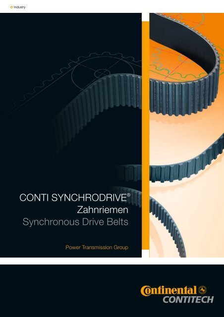
<strong>CONTI</strong> SYNCHRODRIVE ®<br />
<strong>Zahnriemen</strong><br />
<strong>Synchronous</strong> Drive Belts<br />
Power Transmission Group
3–7 1 <strong>CONTI</strong> SYNCHRODRIVE ®<br />
<strong>Zahnriemen</strong><br />
2–4 Eigenschaften<br />
4 Aufbau<br />
5 Bezeichnung<br />
6-7 Lieferprogramm<br />
7 Toleranzen<br />
1 <strong>CONTI</strong> SYNCHRODRIVE ®<br />
<strong>Synchronous</strong> Drive Belts<br />
Properties<br />
Construction<br />
Designation<br />
Product range<br />
Tolerances<br />
9–18 2 Zahnscheiben<br />
10–11 Bezeichnung<br />
11 Mindest-Zähnezahl<br />
13–16 Durchmesser<br />
17 Toleranzen<br />
18 Spannplatten,<br />
Maße und Einspannlängen<br />
2 Pulleys<br />
Designation<br />
Minimum number of teeth<br />
Diameters<br />
Tolerances<br />
Clamps, dimensions and<br />
clamping lengths<br />
19–39 3 Berechnung<br />
von <strong>Zahnriemen</strong>antrieben<br />
20–22 Formelzeichen, Einheiten, Begriffe<br />
22–23 Berechnungsunterlagen<br />
34–36 Berechnungsbeispiel, Hubantrieb<br />
37–39 Berechnungsbeispiel, Linearantrieb<br />
3 Calculation<br />
of <strong>Synchronous</strong> Belt Drives<br />
Glossary of symbols and terms<br />
Drive calculation data<br />
Example of design procedure steps:<br />
Lifting drive<br />
Example of design procedure steps:<br />
Linear drive<br />
40–44 Stichwortverzeichnis<br />
Index
Eigenschaften / Properties<br />
Aufbau / Construction<br />
Bezeichnung / Designation<br />
Lieferprogramm / Product range<br />
Toleranzen / Tolerances<br />
1 <strong>CONTI</strong> SYNCHRODRIVE ®<br />
<strong>Zahnriemen</strong> / <strong>Synchronous</strong> drive belts
1 <strong>CONTI</strong> SYNCHRODRIVE ® <strong>Zahnriemen</strong> / <strong>Synchronous</strong> drive belts<br />
<strong>CONTI</strong> SYNCHRODRIVE ® <strong>Zahnriemen</strong> für<br />
synchrone Übertragung von Dreh- und Linearbewegungen<br />
<strong>CONTI</strong> SYNCHRODRIVE ® Belts for synchronous<br />
transmission of rotary and linear motion<br />
<strong>CONTI</strong> SYNCHRODRIVE ® <strong>Zahnriemen</strong> sind Antriebselemente<br />
aus hochbeanspruchbarem Polyurethan-Elastomer<br />
mit Stahlcordzugträger. Sie werden nach einem<br />
speziell entwickelten Produktionsverfahren mit hoher Präzision<br />
in endlicher Länge gefertigt.<br />
<strong>CONTI</strong> SYNCHRODRIVE ® <strong>Zahnriemen</strong> werden in endlicher<br />
Ausführung oder auch endlos verschweißt eingesetzt.<br />
In allen Fällen übertragen sie Drehbewegungen winkelgenau<br />
und gleichförmig. <strong>CONTI</strong> SYNCHRODRIVE ®<br />
<strong>Zahnriemen</strong> ermöglichen wirtschaftliche Antriebslösungen<br />
auch bei schwierigen Bedingungen. Ihre Eigenschaften<br />
ergeben funktionsgerechte Antriebslösungen mit großer<br />
Betriebssicherheit und Wartungsfreiheit.<br />
<strong>CONTI</strong> SYNCHRODRIVE ® <strong>Zahnriemen</strong> werden in 10<br />
Zahnprofilen und mehreren Standardbreiten gefertigt. Damit<br />
decken sie weite Einsatzgebiete mit unterschiedlichsten<br />
Belastungen und Bedingungen ab. Beispielhafte<br />
Anwendungen sind Antriebe mit großen Achsabständen,<br />
synchrone Fördersysteme und Transportvorrichtungen<br />
mit Gleitschienen und Positionier- und Reversierantriebe<br />
in der Linear- und Steuertechnik. Moderne Fertigungsverfahren<br />
und Qualitätsprüfungen in allen Verarbeitungsstufen<br />
gewährleisten Produkte größter Zuverlässigkeit mit<br />
gleichbleibend hohem Qualitätsstandard.<br />
<strong>CONTI</strong> SYNCHRODRIVE ® belts are power transmission<br />
products made from a highly durable polyurethane elastomer<br />
incorporating a steel-cord tension member. They<br />
are manufactured precisely to length using a newly developed<br />
production technique.<br />
<strong>CONTI</strong> SYNCHRODRIVE ® belts can be used in the openended<br />
or endless form. In all cases, they ensure that rotary<br />
motion is transmitted uniformly and with angular precision.<br />
<strong>CONTI</strong> SYNCHRODRIVE ® belts permit low-cost<br />
drive designs, even where difficult operating conditions<br />
have to be taken into account. Their properties provide a<br />
highly reliable, maintenance-free solution to even the most<br />
demanding drive problems.<br />
<strong>CONTI</strong> SYNCHRODRIVE ® belts are available in 10 tooth<br />
profiles and several standard widths, covering a host of<br />
different applications involving various loads and service<br />
conditions. They are ideal for drives with a large center distance,<br />
for synchronous conveyor systems and transport<br />
devices with sliding rails as well as for positioning and reversing<br />
drives in linear and control engineering. Modern<br />
production techniques and rigorous in-process quality<br />
controls guarantee products with maximum reliability and<br />
a consistently high standard of quality.<br />
Eigenschaften<br />
Exakte Synchronität<br />
durch formschlüssiges Antriebssystem<br />
Wie bei einem Zahnradantrieb greifen die Zähne des Riemens<br />
direkt in die Verzahnung der Antriebsscheiben. Das<br />
formschlüssige Antriebsprinzip ergibt den synchronen<br />
Lauf und eine jederzeit konstante Umfangsgeschwindigkeit.<br />
Vielseitige Anwendungsmöglichkeiten bei<br />
geringem konstruktivem Aufwand<br />
<strong>CONTI</strong> SYNCHRODRIVE ® <strong>Zahnriemen</strong> können in endlicher<br />
oder endloser Ausführung als synchrone Antriebs-<br />
oder Transportriemen eingesetzt werden. Für<br />
besondere Anwendungen lassen sich <strong>CONTI</strong> SYNCHRO-<br />
DRIVE ® <strong>Zahnriemen</strong> auch mit Steuer- oder Transportno-<br />
Properties<br />
Precise synchronism due to positive engagement<br />
The belt teeth mesh with those of the pulley in the same<br />
manner as the teeth on a gear. This positive drive principle<br />
provides synchronous operation and eliminates speed<br />
variation.<br />
A variety of possible applications at low design cost<br />
<strong>CONTI</strong> SYNCHRODRIVE ® belts can be used as synchronous<br />
drive or transport belts in either the open-ended or<br />
endless version. For special applications, <strong>CONTI</strong> SYN-<br />
CHRODRIVE ® belts can also be heavy-duty bonded to<br />
cams made from thermoplastics for control and transport<br />
functions. As open-ended drive components, <strong>CONTI</strong><br />
SYNCHRODRIVE ® belts are ideal for linear and control drives<br />
that have to transmit rotary motion with repeat accuracy<br />
and multiple positioning control.<br />
2
cken aus Thermoplasten hochbeanspruchbar verschweißen.<br />
Als endliche Antriebselemente eignen sich <strong>CONTI</strong><br />
SYNCHRODRIVE ® <strong>Zahnriemen</strong> hervorragend für Linearund<br />
Steuerantriebe, um Drehbewegungen positionierund<br />
wiederholgenau umzusetzen.<br />
Geringe Wellen- und Lagerbelastung<br />
Das Verzahnungsprinzip erfordert nur eine geringe <strong>Zahnriemen</strong>vorspannung.<br />
Die Wellen- und Lagerbelastungen<br />
bleiben gering.<br />
Geringer Raumbedarf<br />
Die hohe dynamische Belastbarkeit und Flexibilität ermöglichen<br />
die Anwendung kleiner Zahnscheibendurchmesser<br />
und kurzer Wellenabstände sowie die Anordnung<br />
von Rückenspannrollen. Damit können wirtschaftliche Antriebe<br />
mit kleinem Bauvolumen und geringem Gewicht<br />
konstruiert werden.<br />
Kein Wartungsaufwand<br />
<strong>CONTI</strong> SYNCHRODRIVE ® <strong>Zahnriemen</strong> sind wartungsfrei.<br />
Schmieren und Nachspannen sind nicht erforderlich.<br />
Durch die Verwendung von Stahlcordzugträgern hoher<br />
Festigkeit ist nach einer kurzen Einlaufphase eine konstante<br />
Riemenspannung gewährleistet.<br />
Hoher Wirkungsgrad<br />
Die flexible und biegetüchtige <strong>Zahnriemen</strong>ausführung<br />
sowie die gute maßliche Abstimmung der Zahnkontur<br />
von Riemen und Zahnscheiben ermöglichen Antriebe mit<br />
einem Wirkungsgrad von 98%. .<br />
<strong>CONTI</strong> SYNCHRODRIVE ® <strong>Zahnriemen</strong> sind<br />
q abriebfest<br />
q öl- und fettbeständig<br />
q benzin- und benzolbeständig<br />
q hydrolysebeständig<br />
q UV- und ozonbeständig<br />
q temperaturbeständig von – 30 bis 80 °C,<br />
(bitte fordern Sie im Bereich unter –10 °C und<br />
über 50 °C technische Beratung an)<br />
q verschweißbar mit Thermoplasten<br />
Low loads on shafts and bearings<br />
The tooth grip principle requires only low initial belt tensioning.<br />
Thus the load on shafts and bearings is kept to a<br />
minimum.<br />
Compact drive design<br />
High dynamic stability and flexibility allows the use of small<br />
pulley diameters, low center distances, and backside idlers.<br />
This enables a lightweight, low-cost drive setup with<br />
less space requirement.<br />
No maintenance<br />
<strong>CONTI</strong> SYNCHRODRIVE ® belts are maintenance-free; no<br />
lubrication or retensioning is required. Constant belt tension<br />
is guaranteed by the use of a high-strength steel-cord<br />
tension member.<br />
High efficiency<br />
The superb flexural properties of the synchronous drive<br />
belt as well as the exact dimensional mating of the belt<br />
and pulley tooth contours permit drives with an efficiency<br />
of 98%.<br />
<strong>CONTI</strong> SYNCHRODRIVE ® belts are resistant to<br />
q wear<br />
q oil and grease<br />
q petrol and benzene<br />
q hydrolysis<br />
q UV and ozone<br />
q temperatures ranging from – 30°Cto +80°C<br />
(for operational temperatures outside –10 °C to<br />
50 °C please seek advice from our technical experts)<br />
q can be bonded to thermoplastics<br />
3
1 <strong>CONTI</strong> SYNCHRODRIVE ® <strong>Zahnriemen</strong> / <strong>Synchronous</strong> drive belts<br />
Ausführungen<br />
<strong>CONTI</strong> SYNCHRODRIVE ® <strong>Zahnriemen</strong> werden in folgenden<br />
Ausführungen geliefert:<br />
HF q flexible Ausführung,<br />
alle Profile außer 3 mm Teilung<br />
z.B. für Antriebe mit kleinen<br />
Scheibendurchmessern<br />
HP q verstärkte Ausführung<br />
Profile HTD und STD<br />
z.B. für Steuerungssysteme<br />
mit hoher Belastung<br />
HS q hohe Zugträgersteifigkeit<br />
Profile HTD und STD<br />
z.B. für hochpräzise Linearantriebe<br />
XHP q extra hohe Zugfestigkeit<br />
Profil HTD 14M<br />
z.B. für Hubsysteme<br />
PAZ q Gewebearmierung auf der Zahnseite, z.B. für<br />
Transportvorrichtungen mit Gleitschienen.<br />
Antistatische Ausführung aPAZ auf Anfrage.<br />
PAR q Gewebearmierung auf dem Riemenrücken<br />
z.B. für Stauförderer. Antistatische Ausführung<br />
aPAR auf Anfrage.<br />
V q endlos verschweißte <strong>Zahnriemen</strong><br />
in Ausführung HF und Längen ab 1000 mm, alle<br />
Profile außer 3 mm Teilung<br />
z.B. für Rotationsantriebe mit großen<br />
Achsabständen<br />
Weitere Sonderausführungen auf Anfrage.<br />
Belt versions<br />
<strong>CONTI</strong> SYNCHRODRIVE ® belts are supplied in the<br />
following versions:<br />
HF q high flexible version<br />
all profiles except for 3 mm pitch<br />
e.g. for drives with small pulley diameters<br />
HP q high power reinforced version<br />
HTD and STD profiles<br />
e.g. for heavy-duty control systems<br />
HS q high stiffness of tension member<br />
HTD and STD profiles<br />
e.g. for high-precision linear drives<br />
XHP q extremely high power tensile-strength<br />
HTD 14M profile<br />
e.g. for lifting systems<br />
PAZ q with polyamide fabric facing on the pulley side<br />
e.g. for sliding-rail transport systems.<br />
Antistatic aPAZ version on request.<br />
PAR q with polyamide fabric facing on the back of<br />
the belt e.g. for skid-queuing conveyors.<br />
Antistatic aPAR version on request.<br />
V q endless belt in HF version and lengths from<br />
1000 mm, all profiles except for 3 mm pitch<br />
e.g. for rotary drives with large center distances<br />
Other special versions can be supplied on request.<br />
Aufbau<br />
Construction<br />
Polyurethan-Riemenrücken<br />
Stahlcordzugträger<br />
Polyurethan-Zähne<br />
Optional:<br />
Gewebearmierung<br />
zahn-/rückenseitig<br />
Polyurethane belt backing<br />
Steel-cord tension member<br />
Polyurethane teeth<br />
Optional:<br />
Fabric facing in the pulley<br />
side/back of the belt<br />
Die Elemente des <strong>Zahnriemen</strong>s sind:<br />
q Polyurethan-Zähne und -Riemenrücken,<br />
Farbe: schwarz<br />
q Stahlcordzugträger,<br />
Schlagrichtungen zueinander balanciert<br />
Polyurethan-Zähne und -Riemenrücken<br />
Hochbeanspruchbares Polyurethan-Elastomer bildet<br />
Zähne und Riemenrücken mit einer hervorragenden Bindung<br />
zum Zugträger. Die hohe Abriebfestigkeit des Polyurethans<br />
ist die Voraussetzung für störungsfreien Antrieb<br />
und lange Lebensdauer. Dieses wird unterstützt durch die<br />
balancierte Zugträgeranordnung.<br />
Our synchronous drive belts are made up of<br />
q polyurethane teeth and backing,<br />
color: black<br />
q steel-cord tension member,<br />
with balanced right/left-handed cord twist<br />
Polyurethane teeth and backing<br />
Belt teeth and backing are made from a tough polyurethane<br />
elastomer with excellent adhesion to the tension<br />
member. The high wear resistance of the polyurethane<br />
ensures trouble-free drive performance and a long<br />
service life. These features are enhanced even more by<br />
the balanced layout of the tension cords.<br />
4
Stahlcordzugträger<br />
<strong>Zahnriemen</strong> für formschlüssige Antriebssysteme erfordern<br />
eine hohe Längenkonstanz und Zugfestigkeit. Kantenparallel<br />
angeordnete Stahlcordzugträger hoher Festigkeit<br />
gewährleisten große Belastbarkeit der <strong>Zahnriemen</strong><br />
und exaktes Laufverhalten.<br />
Steel-cord tension member<br />
<strong>Synchronous</strong> drive belts for positive drive systems must<br />
have a high resistance to elongation and a high tensile<br />
strength. Extra-strong steel tension cords, laid parallel to<br />
the belt edges, guarantee the belt’s high loading capacity<br />
and accurate running properties.<br />
Bezeichnung<br />
<strong>CONTI</strong> SYNCHRODRIVE ® <strong>Zahnriemen</strong> werden nach den<br />
für die unterschiedlichen Riementypen festgelegten<br />
Standards mit Wirklänge, Zahnteilung und <strong>Zahnriemen</strong>breite<br />
bezeichnet, ergänzt durch Kurzzeichen für die Ausführung,<br />
siehe Seite 4.<br />
q Wirklänge in m<br />
Die Wirklänge des <strong>Zahnriemen</strong>s ist der Gesamtumfang,<br />
gemessen auf der biegeneutralen Wirklinie. Die Wirklänge<br />
liegt in der Mitte des Zugträgers.<br />
q Zahnteilung in mm oder Inch<br />
Die Zahnteilung ist der lineare Abstand zwischen zwei benachbarten<br />
Zähnen in Höhe der Wirklinie.<br />
q <strong>Zahnriemen</strong>breite in mm oder 1/100 Inch<br />
Die <strong>Zahnriemen</strong>breite und die Breitenbezeichnung sind<br />
identisch.<br />
Beispiele<br />
Designation<br />
<strong>CONTI</strong> SYNCHRODRIVE ® synchronous drive belts are<br />
specified in accordance with defined standards for the different<br />
belt types showing the pitch length, tooth pitch and<br />
belt width, plus a code for the belt version, see page 4.<br />
q Pitch length in m<br />
The pitch length of the belt is the overall circumference, or<br />
length measuredat the neutral pitch line. The pitch length<br />
is located in the middle of thetension member.<br />
q Tooth pitch in mm or inches<br />
The tooth pitch is the linear distance between two adjacent<br />
teeth at the pitch line.<br />
q Belt width in mm or hundredths of an inch<br />
The belt width and width designation are identical.<br />
Examples<br />
<strong>CONTI</strong> SYNCHRODRIVE ® HTD <strong>Zahnriemen</strong> / <strong>Synchronous</strong> drive belts – M 30 – 8M – 50 HP<br />
M<br />
endliche Ausführung<br />
30 30 m Wirklänge<br />
8M<br />
8 mm Zahnteilung, Profil HTD<br />
50 50 mm <strong>Zahnriemen</strong>breite<br />
HP<br />
verstärkte Ausführung<br />
M<br />
open-ended type<br />
30 pitch length 30 m<br />
8M<br />
tooth pitch 8 mm , HTD profile<br />
50 belt width 50 mm<br />
HP<br />
reinforced version<br />
<strong>CONTI</strong> SYNCHRODRIVE ® STD <strong>Zahnriemen</strong> / <strong>Synchronous</strong> drive belts – V 2400 – S 5M – 30 HF<br />
V<br />
endlos verschweißte Ausführung<br />
2400 2400 mm Riemenlänge<br />
S 5M<br />
5 mm Zahnteilung, Profil STD<br />
30 30 mm <strong>Zahnriemen</strong>breite<br />
HF<br />
flexible Ausführung<br />
V<br />
endless type<br />
2400 belt length 2400 mm<br />
S 5M<br />
tooth pitch 5 mm, STD profile<br />
30 belt width 30 mm<br />
HF<br />
flexible version<br />
<strong>CONTI</strong> SYNCHRODRIVE ® <strong>Zahnriemen</strong> / <strong>Synchronous</strong> drive belts – 10 x M 30 H 100 PAZ<br />
10 Anzahl der Rollen<br />
M<br />
endliche Ausführung<br />
30 30 m Wirklänge<br />
H<br />
0,5 Inch = 12,7 mm Zahnteilung<br />
100 1,0 Inch = 25,4 mm <strong>Zahnriemen</strong>breite<br />
PAZ<br />
Laufseite mit Gewebearmierung<br />
Die Zähnezahl ergibt sich aus Wirklänge und Teilung:<br />
10 number of rolls<br />
M<br />
open-ended type<br />
30 pitch length 30 m<br />
H<br />
tooth pitch 0.5 Inch = 12.7 mm<br />
100 belt width 1.0 Inch = 25.4 mm<br />
PAZ<br />
with fabric facing on the pulley side<br />
The number of teeth is a function of pitch length and pitch:<br />
z L w<br />
t<br />
5
1 <strong>CONTI</strong> SYNCHRODRIVE ® <strong>Zahnriemen</strong> / <strong>Synchronous</strong> drive belts<br />
Lieferprogramm<br />
Profile<br />
<strong>CONTI</strong> SYNCHRODRIVE ® <strong>Zahnriemen</strong> werden in 10 Profilgrößen<br />
gefertigt. Die Maße der HTD- und STD-<strong>Zahnriemen</strong><br />
entsprechen dem Entwurf ISO/F DIS 13050, die der Trapez-<strong>Zahnriemen</strong><br />
DIN ISO 5296. In Tabelle 1 (Seite 6) sind<br />
die Profilmaße und weitere technische Angaben der lieferbaren<br />
<strong>Zahnriemen</strong> zusammengefaßt. Bei Linearantrieben<br />
mit besonders hohen Genauigkeitsanforderungen ist die<br />
Verwendung von Sonderzahnscheiben erforderlich.<br />
Weitere Angaben zu den Scheiben enthält das Kapitel<br />
Zahnscheiben auf Seite 10.<br />
Längen<br />
<strong>CONTI</strong> SYNCHRODRIVE ® <strong>Zahnriemen</strong> können in endlicher<br />
oder endloser Ausführung eingesetzt werden.<br />
Breiten<br />
<strong>CONTI</strong> SYNCHRODRIVE ® <strong>Zahnriemen</strong> werden in mehreren<br />
Standardbreiten geliefert. Die Maße sind in Tabelle 2<br />
(Seite 7) aufgeführt. Abweichende Breiten auf Anfrage.<br />
Ausführungen<br />
<strong>CONTI</strong> SYNCHRODRIVE ® <strong>Zahnriemen</strong> aus Polyurethan<br />
mit kantenparallel angeordnetem Stahlcordzuträger sind<br />
Präzisionselemente für Anwendungen im Bereich der Antriebs-<br />
und Transporttechnik. Für spezielle Anforderungen<br />
sind <strong>Zahnriemen</strong> in unterschiedlichen Ausführungen lieferbar.<br />
Erläuterungen siehe Abschnitt „Eigenschaften”,<br />
Seiten 2 bis 4.<br />
Product range<br />
Profiles<br />
<strong>CONTI</strong> SYNCHRODRIVE ® belts are manufactured in 10<br />
profile sizes. Dimensions of HTD and STD synchronous<br />
drive belts correspond to the specifications laid down in<br />
ISO/F DIS 13050 (draft version) and those of trapezoidal<br />
belts comply with DIN ISO 5296. Table 1 on page 6 gives<br />
a summary of the profile dimensions as well as other technical<br />
information for the belts we supply. Special pulleys<br />
must be used for linear drives with high precision requirements.More<br />
information about pulleys is given in section<br />
2 on “Pulleys“ which starts on page 10.<br />
Lengths<br />
<strong>CONTI</strong> SYNCHRODRIVE ® belts are available in either the<br />
open-ended or endless version.<br />
Widths<br />
<strong>CONTI</strong> SYNCHRODRIVE ® belts are supplied in several<br />
standard widths. Dimensions are given in Table 2 on<br />
page 7. Other widths are available on request.<br />
Versions<br />
<strong>CONTI</strong> SYNCHRODRIVE ® belts made from polyurethane<br />
with steel cords aligned parallel to the belt edges are precision-made<br />
components for applications in drive and<br />
transportation engineering. Several versions are available<br />
to meet various operating requirements. More details are<br />
given on pages 2 to 4 under “Properties“.<br />
Abb. / Fig. 1 Zahnprofil / Tooth profile Zahnprofil / Tooth profile Zahnprofil / Tooth profile<br />
HTD 3M, HTD 5M, STD S 5M, STD S 8M, XL, L, H<br />
HTD 8M, HTD 14M<br />
STD S 3M auf Anfrage / on request<br />
Tab. 1<br />
Kenndaten / Specifications<br />
Zahnprofil Tooth profile HTD STD Trapez<br />
3M 5M 8M 14M S 3M S 5M S 8M XL L H<br />
Zahnteilung t Tooth pitch t mm 3,00 5,00 8,00 14,00 3,00 5,00 8,00 5,080 9,525 12,700<br />
Inch 0,200 0,375 0,500<br />
Riemendicke h s Belt thickness h s mm 2,4 3,60 5,60 10,00 2,30 3,40 5,20 2,30 3,60 04,30<br />
Zahnhöhe h t Tooth height h t mm 1,3 2,10 3,40 6,10 1,14 1,90 3,00 1,27 1,91 02,29<br />
Gewicht m spez Weight m spez<br />
pro mm Riemenbreite per mm of belt width<br />
Ausführung HF Type HF 10 –3 kg/m 3,36 5,40 10,37 3,21 5,24 2,16 3,65 04,53<br />
HP HP 10 –3 kg/m 3,15 4,06 6,32 11,27 3,08 3,91 6,22<br />
HS HS 10 –3 kg/m 7,22 11,40 4,64 7,12<br />
XHP XHP 10 –3 kg/m 14,00<br />
Standardlänge Standard<br />
Ausführung M L w Type M L w m 30 bzw. / or 60<br />
6
<strong>Zahnriemen</strong>breite / Belt width – b in mm Tab. 2<br />
Zahnprofil Tooth profile HTD STD Trapez<br />
3M 5M 8M 14M S 3M S 5M S 8M XL L H<br />
Weitere Zwischenbreiten auf Anfrage / Other inermedia widths on request<br />
5 5 5 5 6,35<br />
10 10 10 10 10 10 9,53 9,53<br />
15 15 15 15 15 15 12,70 12,70 12,70<br />
20 20 19,05 19,05 19,05<br />
25 25 25 25 25 25,40 25,40<br />
30 30<br />
40 38,10 38,10<br />
50 50 50 50/55 50 50 50 50,80 50,80 50,80<br />
85 85 85<br />
100 100 100<br />
115<br />
120<br />
Toleranzen<br />
<strong>CONTI</strong> SYNCHRODRIVE ® <strong>Zahnriemen</strong> sind Präzisionserzeugnisse.<br />
Ihre Fertigung erfolgt prozesssicher mit hoher<br />
Genauigkeit. Die Abweichungen für Länge, Breite und<br />
Dicke sind äußerst eng toleriert.<br />
Tolerances<br />
<strong>CONTI</strong> SYNCHRODRIVE ® belts are precision-made products.<br />
Manufacturing involves reliable process techniques<br />
and maximum accuracy throughout all stages. Deviations<br />
in length, width and thickness are subject to extremely<br />
tight tolerances.<br />
Toleranzen für <strong>Zahnriemen</strong>längen / Belt length tolerances Tab. 3<br />
Wirklänge / Pitch length L w mm Längentoleranz / Length tolerance %<br />
L w 0,1<br />
Toleranzen für <strong>Zahnriemen</strong>breiten / Belt width tolerances Tab. 4<br />
Zahnprofil Tooth profile HTD STD Trapez<br />
3M 5M 8M 14M S 3M S 5M S 8M XL L H<br />
Riemenbreite b Belt width b bis 25 mm 0,5 0,5 0,6 0,6 0,5 0,5 0,6 0,5 0,6 0,6<br />
25–50 mm 0,6 0,6 0,7 1,0 0,6 0,6 0,7 0,6 0,7 0,7<br />
50 mm 0,8 1,2 0,8 0,8 0,8<br />
Toleranzen für <strong>Zahnriemen</strong>dicken (Ausführung M) / Belt thickness tolerances (Type M) Tab. 5<br />
Zahnprofil Tooth profile HTD STD Trapez<br />
3M 5M 8M 14M S 3M S 5M S 8M XL L H<br />
Riemendicke h s Belt thickness h s mm 2,4 3,6 5,6 10,0 2,3 3,4 5,2 2,3 3,6 4,3<br />
Dickentoleranz Thickness tolerance mm 0,25 0,25 0,4 0,6 0,25 0,25 0,4 0,25 0,4 0,4<br />
7
Bezeichnung /Designation<br />
Mindest-Zähnezahl / Minimum number of teeth<br />
Durchmesser / Diameters<br />
Toleranzen / Tolerances<br />
Einspannlänge / Clamping length<br />
2 Zahnscheiben / Pulleys<br />
9
2 Zahnscheiben / Pulleys<br />
Zahnscheiben<br />
Pulleys<br />
Die Übertragungsgenauigkeit, die Laufruhe und die Lebensdauer<br />
von <strong>Zahnriemen</strong>antrieben werden entscheidend<br />
vom präzisen Zusammenwirken von Riemen und<br />
Zahnscheibe bestimmt.<br />
Die von <strong>ContiTech</strong> weiterentwickelten Zahnlückenprofile<br />
der Zahnscheiben sind den jeweiligen Riemenprofilen ideal<br />
angepasst.<br />
Speziell für <strong>CONTI</strong> SYNCHRODRIVE ® HTD <strong>Zahnriemen</strong><br />
ist der Einsatz dieser optimierten Zahnscheiben zu empfehlen.<br />
Zahnscheiben mit den optimierten Profilen liefert der<br />
Fachhandel.<br />
Für Linearantriebe mit sehr hohen Positionier-Anforderungen<br />
sind Zahnscheiben mit minimiertem Lückenspiel erforderlich.<br />
Bei Sonderausführungen bitte anwendungstechnische<br />
Beratung anfordern.<br />
Bezeichnung<br />
Zahnscheiben für <strong>CONTI</strong> SYNCHRODRIVE ® <strong>Zahnriemen</strong>antriebe<br />
werden nach den für die unterschiedlichen <strong>Zahnriemen</strong>typen<br />
festgelegten Standards mit Zähnezahl,<br />
Zahnteilung und Zahnscheibenbreite sowie Kurzzeichen<br />
für die Ausführung bezeichnet.<br />
q P<br />
Allgemeine Bezeichnung für Zahnscheiben.<br />
q Zähnezahl<br />
Die Zähnezahl der Zahnscheibe errechnet sich aus Wirkumfang<br />
und Teilung:<br />
Precise belt/pulley conformance is vital to ensure accurate<br />
power transmission as well as smooth operation and<br />
a long service life for synchronous belt drives.<br />
<strong>ContiTech</strong> engineers have modified pulley tooth-gap<br />
profiles so that they conform ideally to the respective belt<br />
profiles<br />
Use of these optimized pulleys is recommended especially<br />
for <strong>CONTI</strong> SYNCHRODRIVE ® HTD belts.<br />
Pulleys with optimized profiles are obtainable from your local<br />
pulley supplier.<br />
Linear drives with demanding positioning requirements<br />
need pulleys with minimized gap clearance. If you are<br />
planning a special drive design, please consult our application<br />
engineers for advice.<br />
Designation<br />
Pulleys for <strong>CONTI</strong> SYNCHRODRIVE ® belt drives are identified<br />
in accordance with the standards defined for the various<br />
belt types by their number of teeth, tooth pitch and<br />
pulley width, as well as a code denoting the type of pulley.<br />
q P<br />
General designation for toothed pulleys.<br />
q Number of teeth<br />
The pulley’s number of teeth is calculated from the pitch<br />
circumference and the pitch:<br />
U<br />
z w<br />
· d w<br />
t t<br />
q Zahnteilung in mm oder Inch<br />
Die Zahnteilung der Zahnscheibe ist der Abstand zwischen<br />
zwei Bezugspunkten benachbarter Zähne auf dem<br />
Umfang des Wirkdurchmessers. Der Wirkdurchmesser ist<br />
um den doppelten Betrag des Wirklinienabstandes des<br />
zugehörigen <strong>Zahnriemen</strong>s größer als der Zahnscheiben-<br />
Außendurchmesser und liegt in der Höhe der Wirklinie des<br />
<strong>Zahnriemen</strong>s.<br />
q Zahnscheibenbreite in mm oder 1/100 Inch<br />
Die Breitenbezeichnung gibt die genaue Breite des zugehörigen<br />
<strong>Zahnriemen</strong>s, nicht aber die genaue Scheibenbreite<br />
an.<br />
q Angaben für Bordscheiben<br />
F bedeutet beidseitig Bordscheiben.<br />
Bordscheiben verhindern das Ablaufen von <strong>Zahnriemen</strong>.<br />
Es ist erforderlich, mindestens eine Zahnscheibe mit 2<br />
Bordscheiben zu versehen. Aus Kostengründen sollte<br />
hierfür die kleinere Zahnscheibe gewählt werden. Auch<br />
das wechselseitige Anbringen von je 1 Bordscheibe pro<br />
Zahnscheibe ist möglich.<br />
q Tooth pitch in mm or inches<br />
The tooth pitch of the pulley is the distance between two<br />
reference points on adjacent teeth at the circumference of<br />
the pitch diameter. The pitch diameter is larger than the<br />
outside diameter of the pulley by double the thickness at<br />
which the pitch line of belt rides above the pulley.<br />
q Pulley width in mm or hundredths of an inch<br />
The width designation defines the exact width of the corresponding<br />
synchronous drive belt, and not that of the<br />
pulley.<br />
q Flanged pulley data<br />
F stands for pulleys that are flanged on both sides.<br />
Flanged pulleys prevent the belt from riding off. At least<br />
one pulley with two flanges must be used and generally,<br />
for economy, the smaller pulley of a drive is the flanged<br />
pulley. It is also possible to provide each pulley with one<br />
flange on alternate sides.<br />
10
Beispiele<br />
HTD Zahnscheibe / Pulley – P 36 – 8M – 40<br />
P<br />
Zahnscheibe<br />
36 36 Zähne<br />
8M<br />
8 mm Zahnteilung, Profil HTD<br />
40 Zahnscheibe für 40 mm breite <strong>Zahnriemen</strong><br />
Examples<br />
P<br />
Designation for toothed pulley<br />
36 36 teeth<br />
8M<br />
8 mm tooth pitch, HTD profile<br />
40 Pulley designation for a 40 mm wide<br />
synchronous drive belt<br />
STD Zahnscheibe / Pulley – P 48 – S 5M – 30<br />
P<br />
Zahnscheibe<br />
48 48 Zähne<br />
S 5M<br />
5 mm Zahnteilung, Profil STD<br />
30 Zahnscheibe für 30 mm breite <strong>Zahnriemen</strong><br />
P<br />
Designation for toothed pulley<br />
48 48 teeth<br />
S 5M<br />
5mm tooth pitch, STD profile<br />
30 Pulley designation for a 30 mm wide<br />
synchronous drive belt<br />
Zahnscheibe / Pulley – P 48 H 100 F<br />
P<br />
Zahnscheibe<br />
48 48 Zähne<br />
H<br />
Zahnteilung 0,5 Inch = 12,7 mm<br />
100 Zahnscheibe für 25,4 mm breite <strong>Zahnriemen</strong><br />
F<br />
beidseitig Bordscheiben<br />
P<br />
Designation for toothed pulley<br />
48 48 teeth<br />
H<br />
Tooth pitch 0.5 inch = 12.7 mm<br />
100 Pulley designation for a 25.4 mm wide<br />
synchronous drive belt<br />
F<br />
Pulley flanged on both sides<br />
Mindest-Zähnezahl<br />
Für Antriebe mit <strong>CONTI</strong> SYNCHRODRIVE ® <strong>Zahnriemen</strong> sollten<br />
Mindest-Zähnezahlen nicht unterschritten werden. Die<br />
Mindest-Zähnezahl z min und der Mindest-Wirkdurchmesser<br />
d w min für Zahnscheiben sowie die Mindest-Durchmesser<br />
d min für Innen- und Außenspannrollen, die bei der Auslegung<br />
eines Antriebes zu berücksichtigen sind, enthält<br />
Tabelle 6. Innenspannrollen sollten als Zahnscheiben ausgeführt<br />
werden.<br />
Minimum number of teeth<br />
Drives fitted with <strong>CONTI</strong> SYNCHRODRIVE ® belts should<br />
have pulleys that meet the specified minimum number of<br />
teeth. Table 6 shows the minimum number of teeth z min and<br />
the minimum pitch diameter d w min for pulleys as well as the<br />
minimum diameter dmin for inside and outside idlers that are<br />
to be considered when designing a drive. Inside idlers<br />
should be pulleys.<br />
Mindest-Zähnezahl / Minimum number of teeth – z min Tab. 6<br />
Zahnprofil / Tooth profile HTD STD Trapez<br />
3M 5M 8M 14M S 3M S 5M S 8M XL L H<br />
Mindest-ZähnezahI / Minimum number of teeth z min<br />
Ausführung / Type HF 12 16 18 12 16 10 12 14<br />
HP 20 16 20 26 20 16 20<br />
HS 28 30 24 28<br />
XHP 34<br />
Mindest-Wirkdurchmesser / Minimum pitch Ø d w min<br />
Ausführung / Type HF mm 19,10 40,74 80,21 19,10 40,74 16,17 36,38 56,60<br />
HP mm 19,10 25,46 50,93 115,86 19,10 25,46 50,93<br />
HS mm 71,30 133,69 38,20 71,30<br />
XHP mm 151,52<br />
Mindest-Spannrollendurchmesser / Minimum Ø of idler d min<br />
Ausführung / Type HF innen / inside mm 19,10 40,74 80,21 19,10 40,74 19,40 39,41 60,64<br />
außen / outside mm 30,00 60,00 120,00 30,00 60,00 30,00 60,00 90,00<br />
HP innen / inside mm 19,10 25,46 50,93 115,86 19,10 25,46 50,93<br />
außen / outside mm 30,00 50,00 100,00 160,00 30,00 50,00 100,00<br />
HS innen / inside mm 71,30 133,69 44,56 71,30<br />
außen / outside mm 120,00 180,00 80,00 120,00<br />
XHP innen / inside mm 151,52<br />
außen / outside mm 200,00<br />
Scheibendurchmesser für Ausführung V, Einbausituation Omega: Bitte Beratung anfordern.<br />
Minimum diameter Belt version V with omega pulley configuration: please call for technical support.<br />
11
2 Zahnscheiben / Pulleys<br />
Durchmesser<br />
Zähnezahlen, Wirk- und Außendurchmesser von Zahnscheiben<br />
für Antriebe mit <strong>CONTI</strong> SYNCHRODRIVE ®<br />
<strong>Zahnriemen</strong> sind in den Tabellen 7 bis 16 (Seiten 12 bis 16)<br />
aufgeführt.<br />
Diameters<br />
Number of teeth, pitch and outside diameter of pulleys<br />
for drives fitted with <strong>CONTI</strong> SYNCHRODRIVE ® belts are<br />
contained in Tables 7 to 16 on pages 12 to 16.<br />
Tab. 7<br />
Zahnscheiben für / Pulleys for <strong>CONTI</strong> SYNCHRODRIVE ® HTD <strong>Zahnriemen</strong> / synchronous drive belts<br />
Zahnteilung 3 mm, Profil 3M (Maße in mm) / 3 mm tooth pitch, 3M profile (measurement in mm)<br />
Zähne- Wirk- Außenzahl<br />
Zähne- Wirk- Außen-<br />
Zähne- Wirk- Außen-<br />
Zähne- Wirk- Außenzahl<br />
z d w d a z d w d a z d w d a z d w d a<br />
Ø Ø<br />
Ø Ø zahl Ø Ø zahl Ø Ø<br />
Number of Pitch Outside Number of Pitch Outside Number of Pitch Outside Number of Pitch Outside<br />
teeth diameter diameter teeth diameter diameter teeth diameter diameter teeth diameter diameter<br />
20 19,10 18,34 35 33,42 32,66 50 47,75 46,99 65 62,07 61,31<br />
21 20,05 19,29 36 34,38 33,62 51 48,70 47,94 66 63,03 62,27<br />
22 21,01 20,25 37 35,33 34,57 52 49,66 48,90 67 63,98 63,22<br />
23 21,96 21,20 38 36,29 35,53 53 50,61 49,85 68 64,94 64,18<br />
24 22,92 22,16 39 37,24 36,48 54 51,57 50,81 69 65,89 65,13<br />
25 23,87 23,11 40 38,20 37,44 55 52,52 51,75 70 66,85 66,09<br />
26 24,83 24,07 41 39,15 38,39 56 53,48 52,72 71 67,80 67,04<br />
27 25,78 25,02 42 40,11 39,35 57 54,43 53,67 72 68,75 67,99<br />
28 26,74 25,98 43 41,06 40,30 58 55,39 54,63<br />
29 27,69 26,93 44 42,02 41,26 59 56,34 55,58<br />
30 28,65 27,89 45 42,97 42,21 60 57,30 56,54<br />
31 29,60 28,84 46 43,93 43,17 61 58,25 57,49<br />
32 30,56 29,80 47 44,88 44,12 62 59,21 58,45<br />
33 31,51 30,75 48 45,84 45,08 63 60,16 59,40<br />
34 32,47 31,71 49 46,79 46,03 64 61,12 60,36<br />
Tab. 8<br />
Zahnscheiben für / Pulleys for <strong>CONTI</strong> SYNCHRODRIVE ® HTD <strong>Zahnriemen</strong> / synchronous drive belts<br />
Zahnteilung 5 mm, Profil 5M (Maße in mm) / 5 mm tooth pitch, 5M profile (measurement in mm)<br />
Zähne- Wirk- Außenzahl<br />
Zähne- Wirk- Außen-<br />
Zähne- Wirk- Außen-<br />
Zähne- Wirk- Außenzahl<br />
z d w d a z d w d a z d w d a z d w d a<br />
Ø Ø<br />
Ø Ø zahl Ø Ø zahl Ø Ø<br />
Number of Pitch Outside Number of Pitch Outside Number of Pitch Outside Number of Pitch Outside<br />
teeth diameter diameter teeth diameter diameter teeth diameter diameter teeth diameter diameter<br />
12 19,10 17,96 28 44,56 43,42 44 70,03 68,89 60 95,49 94,35<br />
13 20,69 19,55 29 46,15 45,01 45 71,62 70,48 61 97,08 95,94<br />
14 22,28 21,14 30 47,75 46,61 46 73,21 72,07 62 98,68 97,54<br />
15 23,87 22,73 31 49,34 48,20 47 74,80 73,66 63 100,27 99,13<br />
16 25,46 24,32 32 50,93 49,79 48 76,39 75,25 64 101,86 100,72<br />
17 27,06 25,92 33 52,52 51,38 49 77,99 76,85 65 103,45 102,31<br />
18 28,65 27,51 34 54,11 52,97 50 79,58 78,44 66 105,04 103,90<br />
19 30,24 29,10 35 55,70 54,56 51 81,17 80,03 67 106,63 105,49<br />
20 31,83 30,69 36 57,30 56,16 52 82,76 81,62 68 108,23 107,09<br />
21 33,42 32,28 37 58,89 57,75 53 84,35 83,21 69 109,82 108,68<br />
22 35,01 33,87 38 60,48 59,34 54 85,94 84,80 70 111,41 110,27<br />
23 36,61 35,47 39 62,07 60,93 55 87,54 86,40 71 113,00 111,86<br />
24 38,20 37,06 40 63,66 62,52 56 89,13 87,99 72 114,59 113,45<br />
25 39,79 38,65 41 65,25 64,11 57 90,72 89,58<br />
26 41,38 40,24 42 66,85 65,71 58 92,31 91,17<br />
27 42,97 41,83 43 68,44 67,30 59 93,90 92,76<br />
12
Zahnscheiben für / Pulleys for <strong>CONTI</strong> SYNCHRODRIVE ® HTD <strong>Zahnriemen</strong> / synchronous drive belts<br />
Tab. 9<br />
Zahnteilung 8 mm, Profil 8M (Maße in mm) / 8 mm tooth pitch, 8M profile (measurement in mm)<br />
Zähne- Wirk- Außenzahl<br />
Zähne- Wirk- Außen-<br />
Zähne- Wirk- Außen-<br />
Zähne- Wirk- Außenzahl<br />
z d w d a z d w d a z d w d a z d w d a<br />
Ø Ø<br />
Ø Ø zahl Ø Ø zahl Ø Ø<br />
Number of Pitch Outside Number of Pitch Outside Number of Pitch Outside Number of Pitch Outside<br />
teeth diameter diameter teeth diameter diameter teeth diameter diameter teeth diameter diameter<br />
16 40,74 39,37 31 78,94 77,57 46 117,14 115,77 61 155,34 153,97<br />
17 43,29 41,92 32 81,49 80,12 47 119,68 118,31 62 157,88 156,51<br />
18 45,84 44,47 33 84,03 82,66 48 122,23 120,86 63 160,43 159,06<br />
19 48,38 47,01 34 86,58 85,21 49 124,78 123,41 64 162,97 161,60<br />
20 50,93 49,56 35 89,13 87,76 50 127,32 125,95 65 165,52 164,15<br />
21 53,48 52,11 36 91,67 90,30 51 129,87 128,50 66 168,07 166,70<br />
22 56,02 54,65 37 94,22 92,85 52 132,42 131,05 67 170,61 169,24<br />
23 58,57 57,20 38 96,77 95,40 53 134,96 133,59 68 173,16 171,79<br />
24 61,12 59,75 39 99,31 97,94 54 137,51 136,14 69 175,71 174,34<br />
25 63,66 62,29 40 101,86 100,49 55 140,06 138,69 70 178,25 176,88<br />
26 66,21 64,84 41 104,41 103,04 56 142,60 141,23 71 180,80 179,43<br />
27 68,75 67,38 42 106,95 105,58 57 145,15 143,78 72 183,35 181,98<br />
28 71,30 69,93 43 109,50 108,13 58 147,70 146,33<br />
29 73,85 72,48 44 112,05 110,68 59 150,24 148,87<br />
30 76,39 75,02 45 114,59 113,22 60 152,79 151,42<br />
Zahnscheiben für / Pulleys for <strong>CONTI</strong> SYNCHRODRIVE ® HTD <strong>Zahnriemen</strong> / synchronous drive belts<br />
Tab. 10<br />
Zahnteilung 14 mm, Profil 14M (Maße in mm) / 14 mm tooth pitch, 14M profile (measurement in mm)<br />
Zähne- Wirk- Außenzahl<br />
Zähne- Wirk- Außen-<br />
Zähne- Wirk- Außen-<br />
Zähne- Wirk- Außenzahl<br />
z d w d a z d w d a z d w d a z d w d a<br />
Ø Ø<br />
Ø Ø zahl Ø Ø zahl Ø Ø<br />
Number of Pitch Outside Number of Pitch Outside Number of Pitch Outside Number of Pitch Outside<br />
teeth diameter diameter teeth diameter diameter teeth diameter diameter teeth diameter diameter<br />
18 80,21 77,41 33 147,06 144,26 48 213,90 211,10 63 280,75 277,95<br />
19 84,67 81,87 34 151,52 148,71 49 218,36 215,56 64 285,20 282,40<br />
20 89,13 86,33 35 155,97 153,17 50 222,82 220,02 65 289,66 286,86<br />
21 93,58 90,78 36 160,43 157,63 51 227,27 224,47 66 294,12 291,32<br />
22 98,04 95,24 37 164,88 162,08 52 231,73 228,93 67 298,57 295,77<br />
23 102,50 99,70 38 169,34 166,54 53 236,18 233,38 68 303,03 300,23<br />
24 106,95 104,15 39 173,80 171,00 54 240,64 237,84 69 307,48 304,68<br />
25 111,41 108,61 40 178,25 175,45 55 245,10 242,30 70 311,94 309,14<br />
26 115,86 113,06 41 182,71 179,91 56 249,55 246,75 71 316,40 313,60<br />
27 120,32 117,52 42 187,16 184,36 57 254,01 251,21 72 320,85 318,05<br />
28 124,78 121,98 43 191,62 188,82 58 258,47 255,67<br />
29 129,23 126,43 44 196,08 193,28 59 262,92 260,12<br />
30 133,69 130,89 45 200,53 197,73 60 267,38 264,58<br />
31 138,15 135,35 46 204,99 202,19 61 271,83 269,03<br />
32 142,50 139,80 47 209,45 206,65 62 276,29 273,49<br />
13
2 Zahnscheiben / Pulleys<br />
Tab. 11<br />
Zahnscheiben für / Pulleys for <strong>CONTI</strong> SYNCHRODRIVE ® STD <strong>Zahnriemen</strong> / synchronous drive belts<br />
Zahnteilung 3 mm, Profil S 3M (Maße in mm) / 3 mm tooth pitch, S 3M profile (measurement in mm)<br />
Zähne- Wirk- Außenzahl<br />
Zähne- Wirk- Außen-<br />
Zähne- Wirk- Außen-<br />
Zähne- Wirk- Außenzahl<br />
z d w d a z d w d a z d w d a z d w d a<br />
Ø Ø<br />
Ø Ø zahl Ø Ø zahl Ø Ø<br />
Number of Pitch Outside Number of Pitch Outside Number of Pitch Outside Number of Pitch Outside<br />
teeth diameter diameter teeth diameter diameter teeth diameter diameter teeth diameter diameter<br />
20 19,10 18,34 35 33,42 32,66 50 47,75 46,99 65 62,07 61,31<br />
21 20,05 19,29 36 34,38 33,62 51 48,70 47,94 66 63,03 62,27<br />
22 21,01 20,25 37 35,33 34,57 52 49,66 48,90 67 63,98 63,22<br />
23 21,96 21,20 38 36,29 35,53 53 50,61 49,85 68 64,94 64,18<br />
24 22,92 22,16 39 37,24 36,48 54 51,57 50,81 69 65,89 65,13<br />
25 23,87 23,11 40 38,20 37,44 55 52,52 51,75 70 66,85 66,09<br />
26 24,83 24,07 41 39,15 38,39 56 53,48 52,72 71 67,80 67,04<br />
27 25,78 25,02 42 40,11 39,35 57 54,43 53,67 72 68,75 67,99<br />
28 26,74 25,98 43 41,06 40,30 58 55,39 54,63<br />
29 27,69 26,93 44 42,02 41,26 59 56,34 55,58<br />
30 28,65 27,89 45 42,97 42,21 60 57,30 56,54<br />
31 29,60 28,84 46 43,93 43,17 61 58,25 57,49<br />
32 30,56 29,80 47 44,88 44,12 62 59,21 58,45<br />
33 31,51 30,75 48 45,84 45,08 63 60,16 59,40<br />
34 32,47 31,71 49 46,79 46,03 64 61,12 60,36<br />
Tab. 12<br />
Zahnscheiben für / Pulleys for <strong>CONTI</strong> SYNCHRODRIVE ® STD <strong>Zahnriemen</strong> / synchronous drive belts<br />
Zahnteilung 5 mm, Profil S 5M (Maße in mm) / 5 mm tooth pitch, S 5M profile (measurement in mm)<br />
Zähne- Wirk- Außenzahl<br />
Zähne- Wirk- Außen-<br />
Zähne- Wirk- Außen-<br />
Zähne- Wirk- Außenzahl<br />
z d w d a z d w d a z d w d a z d w d a<br />
Ø Ø<br />
Ø Ø zahl Ø Ø zahl Ø Ø<br />
Number of Pitch Outside Number of Pitch Outside Number of Pitch Outside Number of Pitch Outside<br />
teeth diameter diameter teeth diameter diameter teeth diameter diameter teeth diameter diameter<br />
12 19,10 18,14 28 44,56 43,60 44 70,03 69,07 60 95,49 94,53<br />
13 20,69 19,73 29 46,15 45,19 45 71,62 70,66 61 97,08 96,12<br />
14 22,28 21,32 30 47,75 46,79 46 73,21 72,25 62 98,68 97,72<br />
15 23,87 22,91 31 49,34 48,38 47 74,80 73,84 63 100,27 99,31<br />
16 25,46 24,50 32 50,93 49,97 48 76,39 75,43 64 101,86 100,90<br />
17 27,06 26,10 33 52,52 51,56 49 77,99 77,03 65 103,45 102,49<br />
18 28,65 27,69 34 54,11 53,15 50 79,58 78,62 66 105,04 104,08<br />
19 30,24 29,28 35 55,70 54,74 51 81,17 80,21 67 106,63 105,67<br />
20 31,83 30,87 36 57,30 56,34 52 82,76 81,80 68 108,23 107,27<br />
21 33,42 32,46 37 58,89 57,93 53 84,35 83,39 69 109,82 108,86<br />
22 35,01 34,05 38 60,48 59,52 54 85,94 84,98 70 111,41 110,45<br />
23 36,61 35,65 39 62,07 61,11 55 87,54 86,58 71 113,00 112,04<br />
24 38,20 37,24 40 63,66 62,70 56 89,13 88,17 72 114,59 113,63<br />
25 39,79 38,83 41 65,25 64,29 57 90,72 89,76<br />
26 41,38 40,42 42 66,85 65,89 58 92,31 91,35<br />
27 42,97 42,01 43 68,44 67,48 59 93,90 92,94<br />
14
Zahnscheiben für / Pulleys for <strong>CONTI</strong> SYNCHRODRIVE ® STD <strong>Zahnriemen</strong> / synchronous drive belts<br />
Tab. 13<br />
Zahnteilung 8 mm, Profil S 8M (Maße in mm) / 8 mm tooth pitch, S 8M profile (measurement in mm)<br />
Zähne- Wirk- Außenzahl<br />
Zähne- Wirk- Außen-<br />
Zähne- Wirk- Außen-<br />
Zähne- Wirk- Außenzahl<br />
z d w d a z d w d a z d w d a z d w d a<br />
Ø Ø<br />
Ø Ø zahl Ø Ø zahl Ø Ø<br />
Number of Pitch Outside Number of Pitch Outside Number of Pitch Outside Number of Pitch Outside<br />
teeth diameter diameter teeth diameter diameter teeth diameter diameter teeth diameter diameter<br />
16 40,74 39,37 31 78,94 77,57 46 117,14 115,77 61 155,34 153,97<br />
17 43,29 41,92 32 81,49 80,12 47 119,68 118,31 62 157,88 156,51<br />
18 45,84 44,47 33 84,03 82,66 48 122,23 120,86 63 160,43 159,06<br />
19 48,38 47,01 34 86,58 85,21 49 124,78 123,41 64 162,97 161,60<br />
20 50,93 49,56 35 89,13 87,76 50 127,32 125,95 65 165,52 164,15<br />
21 53,48 52,11 36 91,67 90,30 51 129,87 128,50 66 168,07 166,70<br />
22 56,02 54,65 37 94,22 92,85 52 132,42 131,05 67 170,61 169,24<br />
23 58,57 57,20 38 96,77 95,40 53 134,96 133,59 68 173,16 171,79<br />
24 61,12 59,75 39 99,31 97,94 54 137,51 136,14 69 175,71 174,34<br />
25 63,66 62,29 40 101,86 100,49 55 140,06 138,69 70 178,25 176,88<br />
26 66,21 64,84 41 104,41 103,04 56 142,60 141,23 71 180,80 179,43<br />
27 68,75 67,38 42 106,95 105,58 57 145,15 143,78 72 183,35 181,98<br />
28 71,30 69,93 43 109,50 108,13 58 147,70 146,33<br />
29 73,85 72,48 44 112,05 110,68 59 150,24 148,87<br />
30 76,39 75,02 45 114,59 113,22 60 152,79 151,42<br />
Zahnscheiben für / Pulleys for <strong>CONTI</strong> SYNCHRODRIVE ® <strong>Zahnriemen</strong> / synchronous drive belts<br />
Tab. 14<br />
Zahnteilung 0,200 Inch = 5,080 mm, Profil XL (Maße in mm) / 0,200 Inch = 5,080 mm, XL profile (measurement in mm)<br />
Zähne- Wirk- Außenzahl<br />
Zähne- Wirk- Außen-<br />
Zähne- Wirk- Außen-<br />
Zähne- Wirk- Außenzahl<br />
z d w d a z d w d a z d w d a z d w d a<br />
Ø Ø<br />
Ø Ø zahl Ø Ø zahl Ø Ø<br />
Number of Pitch Outside Number of Pitch Outside Number of Pitch Outside Number of Pitch Outside<br />
teeth diameter diameter teeth diameter diameter teeth diameter diameter teeth diameter diameter<br />
10 16,17 15,66 29 46,89 46,39 48 77,62 77,11 67 108,34 107,83<br />
11 17,79 17,28 30 48,51 48,00 49 79,23 78,73 68 109,96 109,45<br />
12 19,40 18,90 31 50,13 49,62 50 80,85 80,34 69 111,57 111,07<br />
13 21,02 20,51 32 51,74 51,24 51 82,47 81,96 70 113,19 112,68<br />
14 22,64 22,13 33 53,36 52,85 52 84,08 83,58 71 114,81 114,30<br />
15 24,26 23,75 34 54,98 54,47 53 85,70 85,19 72 116,43 115,92<br />
16 25,87 25,36 35 56,60 56,09 54 87,32 86,81<br />
17 27,49 26,98 36 58,21 57,70 55 88,94 88,43<br />
18 29,11 28,60 37 59,83 59,32 56 90,55 90,04<br />
19 30,72 30,22 38 61,45 60,94 57 92,17 91,66<br />
20 32,34 31,83 39 63,06 62,56 58 93,79 93,28<br />
21 33,96 33,45 40 64,68 64,17 59 95,40 94,90<br />
22 35,57 35,07 41 66,30 65,79 60 97,02 96,51<br />
23 37,19 36,68 42 67,91 67,41 61 98,64 98,13<br />
24 38,81 38,30 43 69,53 69,02 62 100,25 99,75<br />
25 40,43 39,92 44 71,15 70,64 63 101,87 101,36<br />
26 42,04 41,53 45 72,77 72,26 64 103,49 102,98<br />
27 43,66 43,15 46 74,38 73,87 65 105,11 104,60<br />
28 45,28 44,77 47 76,00 75,49 66 106,72 106,21<br />
15
2 Zahnscheiben / Pulleys<br />
Tab. 15<br />
Zahnscheiben für / Pulleys for <strong>CONTI</strong> SYNCHRODRIVE ® <strong>Zahnriemen</strong> / synchronous drive belts<br />
Zahnteilung 0,375 Inch = 9,525 mm, Profil L (Maße in mm) / 0,375 Inch = 9,525 mm, L profile (measurement in mm)<br />
Zähne- Wirk- Außenzahl<br />
Zähne- Wirk- Außen-<br />
Zähne- Wirk- Außen-<br />
Zähne- Wirk- Außenzahl<br />
z d w d a z d w d a z d w d a z d w d a<br />
Ø Ø<br />
Ø Ø zahl Ø Ø zahl Ø Ø<br />
Number of Pitch Outside Number of Pitch Outside Number of Pitch Outside Number of Pitch Outside<br />
teeth diameter diameter teeth diameter diameter teeth diameter diameter teeth diameter diameter<br />
12 36,38 35,62 28 84,89 84,13 44 133,40 132,64 60 181,91 181,15<br />
13 39,41 38,65 29 87,93 87,16 45 136,44 135,67 61 184,95 184,18<br />
14 42,45 41,68 30 90,96 90,20 46 139,47 138,71 62 187,98 187,22<br />
15 45,48 44,72 31 93,99 93,23 47 142,50 141,74 63 191,01 190,25<br />
16 48,51 47,75 32 97,02 96,26 48 145,53 144,77 64 194,04 193,28<br />
17 51,54 50,78 33 100,05 99,29 49 148,56 147,80 65 197,07 196,31<br />
18 54,57 53,81 34 103,08 102,32 50 151,60 150,83 66 200,11 199,34<br />
19 57,61 56,84 35 106,12 105,35 51 154,63 153,86 67 203,14 202,38<br />
20 60,64 59,88 36 109,15 108,39 52 157,66 156,90 68 206,17 205,41<br />
21 63,67 62,91 37 112,18 111,42 53 160,69 159,93 69 209,20 208,44<br />
22 66,70 65,94 38 115,21 114,45 54 163,72 162,96 70 212,23 211,47<br />
23 69,73 68,97 39 118,24 117,48 55 166,75 165,99 71 215,27 214,50<br />
24 72,77 72,00 40 121,28 120,51 56 169,79 169,02 72 218,30 217,53<br />
25 75,80 75,04 41 124,31 123,55 57 172,82 172,06<br />
26 78,83 78,07 42 127,34 126,58 58 175,85 175,09<br />
27 81,86 81,10 43 130,37 129,61 59 178,88 178,12<br />
Tab. 16<br />
Zahnscheiben für / Pulleys for <strong>CONTI</strong> SYNCHRODRIVE ® <strong>Zahnriemen</strong> / synchronous drive belts<br />
Zahnteilung 0,500 Inch = 12,700 mm, Profil H (Maße in mm) / 0,500 Inch = 12,700 mm, H profile (measurement in mm)<br />
Zähne- Wirk- Außenzahl<br />
Zähne- Wirk- Außen-<br />
Zähne- Wirk- Außen-<br />
Zähne- Wirk- Außenzahl<br />
z d w d a z d w d a z d w d a z d w d a<br />
Ø Ø<br />
Ø Ø zahl Ø Ø zahl Ø Ø<br />
Number of Pitch Outside Number of Pitch Outside Number of Pitch Outside Number of Pitch Outside<br />
teeth diameter diameter teeth diameter diameter teeth diameter diameter teeth diameter diameter<br />
14 56,60 55,20 30 121,28 119,90 46 185,96 184,58 62 250,64 249,27<br />
15 60,64 59,27 31 125,32 123,95 47 190,00 188,63 63 254,68 253,31<br />
16 64,68 63,31 32 129,36 127,99 48 194,04 192,67 64 258,72 257,35<br />
17 68,72 67,35 33 133,40 132,03 49 198,08 196,71 65 262,76 261,39<br />
18 72,77 71,39 34 137,45 136,07 50 202,13 200,75 66 266,81 265,44<br />
19 76,81 75,44 35 141,49 140,12 51 206,17 204,80 67 270,85 269,48<br />
20 80,85 79,48 36 145,53 144,16 52 210,21 208,84 68 274,89 273,52<br />
21 84,89 83,52 37 149,57 148,20 53 214,25 212,88 69 278,93 277,56<br />
22 88,94 87,56 38 153,62 152,24 54 218,30 216,92 70 282,98 281,61<br />
23 92,98 91,61 39 157,66 156,29 55 222,34 220,97 71 287,02 285,65<br />
24 97,02 95,65 40 161,70 160,33 56 226,38 225,01 72 291,06 289,69<br />
25 101,06 99,69 41 165,74 164,37 57 230,42 229,05<br />
26 105,11 103,73 42 169,79 168,41 58 234,47 233,10<br />
27 109,15 107,78 43 173,83 172,46 59 238,51 237,14<br />
28 113,19 111,82 44 177,87 176,50 60 242,55 241,18<br />
29 117,23 115,86 45 181,91 180,54 61 246,59 245,22<br />
16
Toleranzen<br />
Tolerances<br />
Außendurchmesser / Outside diameter tolerances Tab. 17<br />
Außendurchmesser d a mm Toleranz mm Tolerance mm<br />
Outside diameter d a mm<br />
25 0,05 0.05<br />
0 0<br />
25 50 0,08 0.08<br />
0 0<br />
50 100 0,10 0.10<br />
0 0<br />
100 175 0,13 0.13<br />
0 0<br />
175 300 0,15 0.15<br />
0 0<br />
300 500 0,18 0.18<br />
0 0<br />
500 0,20 0.20<br />
0 0<br />
Planlauf-Toleranz / Axial runout tolerances Tab. 18<br />
Außendurchmesser d a mm Toleranz mm Tolerance mm<br />
Outside diameter d a mm<br />
100 0,1 0.1<br />
100 250 0,001 0.001<br />
je mm Außendurchmesser<br />
per mm outside diameter<br />
250 0,25 0,0005 0.25 0.0005<br />
je mm Außendurchmesser<br />
per mm outside diameter<br />
Rundlauf-Toleranz / Radial runout tolerances Tab. 19<br />
Außendurchmesser d a mm Toleranz mm Tolerance mm<br />
Outside diameter d a mm<br />
200 0,13 0.13<br />
200 0,13 0,0005 0.13 0.0005<br />
je mm Außendurchmesser<br />
per mm outside diameter<br />
Parallelität<br />
Die Parallelität zwischen Bohrung und Zähnen darf eine<br />
Abweichung von 1 m pro Millimeter Zahnscheibenbreite<br />
nicht übersteigen.<br />
Konizität<br />
Die Konizität darf höchstens 1 µm je Millimeter der Kopfbreite<br />
betragen und dabei die zulässige Durchmessertoleranz<br />
nicht übersteigen.<br />
Parallelism<br />
Parallelism between the bore and teeth may not exceed<br />
the maximum deviation of 1 m per millimeter of pulley<br />
width.<br />
Draft<br />
The maximum allowable draft is 1 m per millimeter of<br />
face width, but it must not exceed the permissible<br />
diameter tolerance.<br />
17
2 Zahnscheiben / Pulleys<br />
Spannplatten<br />
<strong>CONTI</strong> SYNCHRODRIVE ® <strong>Zahnriemen</strong>, die als endliche<br />
Antriebselemente eingesetzt werden, sind an ihren Enden<br />
formschlüssig zu spannen. Die dazu erforderlichen<br />
Spannplatten müssen mit dem entsprechenden Zahnprofil<br />
versehen sein. Die Spannschrauben sollen auf beiden<br />
Seiten des <strong>Zahnriemen</strong>s angeordnet sein und gleichmäßig<br />
festgezogen werden.<br />
Die Ausführung von Spannplatten ist in Abb. 2 dargestellt.<br />
Die Abmessungen für die Standardausführung sind in Tabelle<br />
20 aufgeführt.<br />
Spannplatten für <strong>CONTI</strong> SYNCHRODRIVE ® <strong>Zahnriemen</strong>antriebe<br />
liefert der Fachhandel.<br />
Clamps<br />
<strong>CONTI</strong> SYNCHRODRIVE ® belts that are used as openended<br />
power transmission components must be clamped<br />
with a positive fit at their ends. Clamps must have the<br />
corresponding tooth profile. The clamping screws should<br />
be positioned on both sides of the belt, and tightened in<br />
a uniform fashion.<br />
Fig. 2 shows the type of clamp used. Dimensions for the<br />
standard type are given in Table 20.<br />
Clamps for <strong>CONTI</strong> SYNCHRODRIVE ® belt drives are<br />
available from drive component dealers.<br />
Abb. / Fig. 2<br />
Spannplatte – Prinzipzeichnung / Clamping plate layout principle<br />
Tab. 20<br />
Abmessungen der Spannplatten (in mm) / Clamping plate dimensions (in mm)<br />
Zahnprofil Tooth profile HTD STD Trapez<br />
3M 5M 8M 14M* S 3M S 5M S 8M XL L H<br />
t t0 5,0 8,0 14,0 0 5,0 8,0 5,080 9,525 12,700<br />
l l 41,4 66,0 116,0 41,4 66,0 42,5 76,6 106,9<br />
e e0 3,2 5,0 9,0 3,2 5,0 3,5 5,0 9,0<br />
h h 8,0 15,0 22,0 8,0 15,0 8,0 15,0 22,0<br />
d d 5,5 9,0 11,0 5,5 9,0 5,5 9,0 1,0<br />
b 1 b 1 6,0 8,0 10,0 6,0 8,0 6,0 8,0 10,0<br />
b 2 b 2 6,35 25,5<br />
für <strong>Zahnriemen</strong>breite for synchronous 9,53 28,5<br />
b mm drive belt width b 10,00 28,0 28,0<br />
b mm 12,70 39,0 45,0<br />
15,00 34,0 40,0 34,0 40,0<br />
19,05 45,0 51,0<br />
20,00 45,0 45,0<br />
25,00 44,0 44,0<br />
25,40 51,5 57,5<br />
30,00 55,0 55,0<br />
40,00 71,0<br />
50,00 75,0 75,0<br />
55,00 86,0<br />
85,00 110,0 116,0 110,0<br />
100,00 131,0<br />
115,00 146,0<br />
120,00 151,0<br />
Spannplatten für STD S 3M und HTD 3M auf Anfrage. / Clamping plates for STD S 3M and HTD 3M are available on request.<br />
* für Version HS und XHP 2 Spannplatten in Reihe anordnen. / * please use for version HS and XHP 2 clamps in line.<br />
18
Formelzeichen, Einheiten, Begriffe / Glossery of symbols and terms<br />
Berechnungsunterlagen / Drive calculation data<br />
Berechnungsbeispiele: / Examples of design procedure steps:<br />
Hubantrieb/ Lifting drive<br />
3 Berechnung von <strong>Zahnriemen</strong>antrieben<br />
Calculation of synchronous belt drives<br />
Linearantrieb / Linear drive<br />
19
3 Berechnung von <strong>Zahnriemen</strong>antrieben / Calculation of synchronous belt drives<br />
Berechnung von<br />
<strong>Zahnriemen</strong>antrieben<br />
Calculation of<br />
synchronous belt drives<br />
Die Berechnung bezieht sich auf Antriebe, die mit <strong>CONTI</strong><br />
SYNCHRODRIVE ® <strong>Zahnriemen</strong> ausgerüstet werden. Die<br />
für die Antriebsauslegung erforderlichen Kenndaten sind in<br />
den nachfolgenden Diagrammen und Tabellen angegeben.<br />
Bei schwierigen Antriebsproblemen empfiehlt es sich, eine<br />
unverbindliche Beratung durch die <strong>ContiTech</strong> Anwendungstechnik<br />
einzuholen.<br />
Calculations are based on drives fitted with <strong>CONTI</strong><br />
SYNCHRODRIVE ® belts. Drive design data are given in<br />
the following diagrams and tables. As so many factors<br />
influence belt performance, it is suggested that designers<br />
of complicated drives consult <strong>ContiTech</strong>’s application<br />
engineers for advice.<br />
Abb. / Fig. 3<br />
<strong>Zahnriemen</strong>-Linearantrieb mit 2 Zahnscheiben ohne Gegenbiegung<br />
<strong>Synchronous</strong> belt linear drive with 2 pulleys and no deflection<br />
Abb. / Fig. 4<br />
<strong>Zahnriemen</strong>-Linearantrieb mit 1 Zahnscheibe und Umlenkrollen<br />
<strong>Synchronous</strong> belt linear drive with 1 pulley and deflection idlers<br />
Formelzeichen,<br />
Einheiten, Begriffe<br />
Glossary of symbols, units<br />
and terms<br />
Zeichen Einheit Definition Symbol Unit Definition<br />
a mm Achsabstand<br />
a mm Spannweg<br />
a b m/s 2 Beschleunigung<br />
a v m/s 2 Bremsverzögerung<br />
b mm, Inch <strong>Zahnriemen</strong>breite<br />
b err mm errechnete <strong>Zahnriemen</strong>breite<br />
c spez N/mm spezifische Federkonstante<br />
pro mm Riemenlänge und<br />
mm Breite<br />
c 0<br />
Gesamtbetriebsfaktor<br />
c 1<br />
Zahneingriffsfaktor<br />
a mm center distance<br />
a mm take up allowance<br />
a b m/s 2 acceleration<br />
a v m/s 2 braking deceleration<br />
b mm, Inch belt width<br />
b err mm calculated belt width<br />
c spez N/mm specific spring constant<br />
per mm of belt length and<br />
mm of width<br />
c 0<br />
overall service factor<br />
c 1<br />
teeth in mesh factor<br />
20
c 1 max<br />
Maximalwert für Zahneingriffsfaktor<br />
c 2<br />
Belastungsfaktor<br />
c 3<br />
Beschleunigungsfaktor<br />
d mm Rollendurchmesser,<br />
Scheibendurchmesser<br />
d a mm Außendurchmesser<br />
der Zahnscheibe<br />
d F mm konstruktionsbedingte<br />
Fertigbohrung<br />
d min mm Mindestdurchmesser<br />
der Spannrolle<br />
d w mm Wirkdurchmesser<br />
der Zahnscheibe<br />
d w1 mm Wirkdurchmesser<br />
der treibenden Zahnscheibe<br />
d w2 mm Wirkdurchmesser<br />
der getriebenen Zahnscheibe<br />
f Hz Eigenfrequenz<br />
F R N Reibkraft<br />
F T N statische Trumkraft<br />
F T max N maximale Trumkraft dynamisch<br />
F u N Umfangskraft<br />
F u max N maximale Umfangskraft<br />
F u spez N spezifische Zahnflankenbelastung<br />
F v N <strong>Zahnriemen</strong>vorspannung,<br />
Wellenbelastung<br />
F zul N zulässige Zugträgerbelastung<br />
g 9,81 m/s 2 Erdbeschleunigung<br />
i<br />
Übersetzung<br />
L f m freie Trumlänge für<br />
Schwingungsanregung<br />
L w mm Wirklänge des <strong>Zahnriemen</strong>s<br />
L w max mm maximale Wirklänge<br />
des <strong>Zahnriemen</strong>s<br />
m ges kg Gesamtmasse<br />
m R kg Masse des <strong>Zahnriemen</strong>s<br />
m S kg Masse des Schlittens<br />
m Sch kg Masse der Zahnscheibe<br />
m Sch red kg reduzierte Masse<br />
der Zahnscheibe<br />
m spez kg/m spez. <strong>Zahnriemen</strong>gewicht<br />
pro m Länge und mm Breite<br />
m U kg Masse der Umlenkrolle<br />
m U red kg reduzierte Masse<br />
der Umlenkrolle<br />
M N/m Drehmoment<br />
n min –1 Drehzahl<br />
n 1 min –1 Drehzahl der<br />
treibenden Zahnscheibe<br />
n 2 min –1 Drehzahl der<br />
getriebenen Zahnscheibe<br />
P kW Leistung<br />
s b m Beschleunigungsweg<br />
c 1 max<br />
maximum value for teeth<br />
in mesh factor<br />
c 2<br />
load factor<br />
c 3<br />
acceleration factor<br />
d mm pulley/idler diameter<br />
d a mm outside diameter of pulley<br />
d F mm design-specific finished bore<br />
d min mm minimum diameter of idler<br />
d w mm pitch diameter of pulley<br />
d w1 mm pitch diameter of driver pulley<br />
d w2 mm pitch diameter of driven pulley<br />
f Hz natural frequency<br />
F R N friction force<br />
F T N static belt tension<br />
F T max N maximum belt tension dynamic<br />
F u N effective pull<br />
F u max N maximum effective pull<br />
F u spez N specific load on tooth flank<br />
F v N belt installation tension,<br />
shaft load<br />
F zul N allowable load on<br />
tension member<br />
g 9,81 m/s 2 gravitational acceleration<br />
i<br />
transmission ratio<br />
L f m free span length for<br />
vibration excitation<br />
L w mm pitch length of belt<br />
L w max mm maximum pitch length of belt<br />
m ges kg total weight<br />
m R kg weight of belt<br />
m S kg weight of carriage<br />
m Sch kg weight of pulley<br />
m Sch red kg reduced weight of pulley<br />
m spez kg/m specific gravity of belt per<br />
m of length and mm of width<br />
m U kg weight of deflection idler<br />
m U red kg reduced weight of<br />
deflection idler<br />
M N/m torque<br />
n min –1 pulley speed<br />
n 1 min –1 speed of driver pulley<br />
n 2 min –1 speed of driven pulley<br />
P kW power<br />
s b m acceleration distance<br />
21
3 Berechnung von <strong>Zahnriemen</strong>antrieben / Calculation of synchronous belt drives<br />
s c m Verfahrweg bei v const<br />
s ges m Gesamtverfahrstrecke<br />
s v m Bremsweg<br />
t mm, Inch Zahnteilung<br />
t c s Verfahrzeit bei v const<br />
U w mm Wirkumfang der Zahnscheibe<br />
v m/s Geschwindigkeit<br />
z<br />
Zähnezahl der Zahnscheibe<br />
z e<br />
eingreifende Zähnezahl<br />
z g<br />
Zähnezahl<br />
der großen Zahnscheibe<br />
z k<br />
Zähnezahl<br />
der kleinen Zahnscheibe<br />
z min<br />
Mindest Zähnezahl<br />
z 1<br />
Zähnezahl<br />
der treibenden Zahnscheibe<br />
z 2<br />
Zähnezahl<br />
der getriebenen Zahnscheibe<br />
° (Grad) Umschlingungswinkel<br />
an der kleinen Zahnscheibe<br />
<br />
Reibungszahl<br />
s c m travel at v const<br />
s ges m total travel<br />
s v m braking distance<br />
t mm, Inch pitch<br />
t c s travel time at v const<br />
U w mm pitch circumference of pulley<br />
v m/s belt speed<br />
z<br />
number of teeth on the pulley<br />
z e<br />
number of meshing teeth<br />
z g<br />
number of teeth on the<br />
large pulley<br />
z k<br />
number of teeth on the<br />
small pulley<br />
z min<br />
minimum number of teeth<br />
z 1<br />
number of teeth on the<br />
driver pulley<br />
z 2<br />
number of teeth on the<br />
driven pulley<br />
° (degrees) arc of contact around the<br />
small pulley<br />
<br />
coefficient of friction<br />
Berechnungsunterlagen<br />
Die Berechnungsunterlagen enthalten alle zur Antriebsdimensionierung<br />
erforderlichen Formeln, Tabellen und<br />
Diagramme. Auf Tabellen, deren Werte mit Hilfe der angegebenen<br />
Formeln selbst errechnet werden können,<br />
wurde verzichtet.<br />
Die zu übertragenden Momente und Umfangskräfte erfordern<br />
bei Berücksichtigung der Maximalwerte und bei<br />
gleichförmiger Belastung keine Sicherheitszuschläge. Bei<br />
zusätzlichen Beanspruchungen durch häufige Schaltvorgänge<br />
oder wechselnde Belastungen sowie durch Beschleunigungs-<br />
oder Bremsvorgänge sind entsprechende<br />
Faktoren einzusetzen.<br />
Gesamtbetriebsfaktor c 0<br />
Der Gesamtbetriebsfaktor c 0 berücksichtigt die durch besondere<br />
Betriebsbedingungen auftretenden Belastungen.<br />
Er errechnet sich aus dem Belastungsfaktor c 2 und dem<br />
Beschleunigungsfaktor c 3 .<br />
Drive calculation data<br />
The following pages contain all the data, formulae and<br />
tables needed when designing a new drive fitted with a<br />
<strong>CONTI</strong> SYNCHRODRIVE ® belt. Tables for values which<br />
can easily be calculated using the formulae provided<br />
have been omitted.<br />
The torques and effective pulls to be transmitted do not<br />
require any safety factors providing the maximum values<br />
are observed and the load is uniform. Corresponding<br />
factors must be applied in the event of frequent shifting<br />
operations and alternating loads as well as with accelerating<br />
or braking processes.<br />
Overall service factor c 0<br />
The overall service factor c 0 takes into consideration the<br />
loads occurring under special operating conditions, and is<br />
the sum of load factor c 2 and acceleration factor c 3 .<br />
c 0 c 2 c 3<br />
Zahneingriffsfaktor c 1<br />
Der Zahneingriffsfaktor c 1 berücksichtigt die Anzahl der in<br />
den <strong>Zahnriemen</strong> eingreifenden Zähne z e der kleinen Zahnscheibe<br />
z k .<br />
Teeth in mesh factor c 1<br />
The teeth in mesh factor c 1 considers the number of teeth<br />
ze of the small pulley z k meshing with the teeth of the synchronous<br />
drive belt.<br />
z e z k ·<br />
<br />
360<br />
Die Berechnung des Umschlingungswinkels ist auf Seite<br />
24 erläutert.<br />
Der Wert des Zahneingriffsfaktors c 1 entspricht der eingreifenden<br />
Zähnezahl z e .<br />
Calculation of the arc of contact is explained on page 24.<br />
The value for teeth in mesh factor c 1 corresponds to the<br />
number of teeth in mesh z e .<br />
22
Dabei gelten folgende Maximalwerte:<br />
c 1 max = 12 für <strong>CONTI</strong> SYNCHRODRIVE ®<br />
<strong>Zahnriemen</strong> Ausführung M<br />
c 2 max = 6 für <strong>CONTI</strong> SYNCHRODRIVE ®<br />
<strong>Zahnriemen</strong> Ausführung V<br />
Die Mindest-Zähnezahlen z min für Zahnscheiben, die bei<br />
der Auslegung eines Antriebes zu berücksichtigen sind,<br />
enthält Tabelle 6 (Seite 11).<br />
Belastungsfaktor c 2<br />
Der Belastungsfaktor c 2 berücksichtigt die Betriebsbedingungen.<br />
Die angegebenen Faktoren sind Richtwerte.<br />
The following maximum values apply:<br />
c 1 max = 12 for <strong>CONTI</strong> SYNCHRODRIVE ®<br />
synchronous drive belts, type M<br />
c 2 max = 6 for <strong>CONTI</strong> SYNCHRODRIVE ®<br />
synchronous drive belts, type V<br />
The minimum numbers of teeth z min for pulleys that are to<br />
be taken into consideration when designing a drive are<br />
contained in Table 6 on page 11.<br />
Load facor c 2<br />
Load factor c 2 is used to compensate for operating conditions.<br />
The factors given below are indicative values only.<br />
Belastungsfaktor c 2 / Load factor c 2 Tab. 21<br />
Übersetzung Operation conditions Belastungsfaktor c 2<br />
Load factor c 2<br />
Beanspruchung gleichförmig Steady load 1,0<br />
Beanspruchung ungleichförmig Fluctuating load<br />
gering low 1,4<br />
mittel average 1,7<br />
hoch high 2,0<br />
Beschleunigungsfaktor c 3<br />
Der Beschleunigungsfaktor c 3 ist bei Übersetzungen ins<br />
Schnelle 1,24 einzusetzen.<br />
Acceleration factor c 3<br />
The acceleration factor c 3 is applied if the step-up transmission<br />
ratio is 1.24.<br />
Beschleunigungsfaktor c 3 / Accelertion factor c 3 Tab. 22<br />
Übersetzung<br />
1<br />
Transmission ration<br />
1<br />
Beschleunigungsfaktor c 3<br />
Acceleration factor c 3<br />
i<br />
i<br />
1 – 1,24 –<br />
1,25 – 1,74 0,1<br />
1,75 – 2,49 0,2<br />
2,50 – 3,49 0,3<br />
3,50 0,4<br />
Übersetzung i<br />
Die Übersetzung i ergibt sich aus dem Verhältnis der<br />
Drehzahlen der Zahnscheiben n 1 und n 2 bzw. den Zähnezahlen<br />
z 2 und z 1 oder den Wirkdurchmessern der<br />
Zahnscheiben d w2 und d w1 .<br />
Transmission ratio i<br />
Transmission ratio i is obtained from the ratio of pulley<br />
speeds n 1 and n 2 or the number of teeth z 2 and z 1 or the<br />
pitch diameters of pulleys d w2 and d w1 .<br />
n 1 z 2<br />
i <br />
z 1<br />
d w2<br />
d w1<br />
n 2<br />
d w mm<br />
Zähnezahl z und<br />
Wirkdurchmesser d w der Zahnscheiben<br />
Die Zähnezahl z und der Wirkdurchmesser d w der Zahnscheiben<br />
werden mit der Teilung t des gewählten Zahnprofils<br />
ermittelt:<br />
Number of teeth z and<br />
pitch diameter d w of the pulleys<br />
The number of teeth z and the pitch diameter d w of the<br />
pulleys are determined by means of pitch t of the chosen<br />
tooth profile.<br />
z · d w<br />
t<br />
z · t<br />
<br />
Zähnezahl, Wirkdurchmesser und Außendurchmesser<br />
von Zahnscheiben sind in den Tabellen 7 bis 16 (Seite 12<br />
bis 16) aufgeführt.<br />
Numbers of teeth, pitch and outside diameters of pulleys<br />
are contained in Tables 7 to 16 on pages 12 to 16.<br />
23
3 Berechnung von <strong>Zahnriemen</strong>antrieben / Calculation of synchronous belt drives<br />
Umschlingungswinkel <br />
Der Umschlingungswinkel an der kleinen Zahnscheibe ist:<br />
Arc of contact <br />
For two-pulley drives, the arc of contact around the<br />
small pulley is calculated as follows:<br />
2 · arccos <br />
t · (z g z k )<br />
2 · · a<br />
<br />
°(Grad)<br />
Bei Mehrscheibenantrieben muss der Umschlingungswinkel<br />
nach der vorgegebenen Geometrie berechnet<br />
werden.<br />
Achsabstand a<br />
Der Achsabstand a wird bei umlaufenden Antrieben mit 2<br />
Scheiben und einem Übersetzungsverhältnis i = 1 wie<br />
folgt berechnet:<br />
For multiple-pulley drives, the arc of contact has to be<br />
calculated in accordance with the given geometry.<br />
Center distance a<br />
Center distance a is calculated as follows for circular path<br />
drives with two pulleys and where transmission ratio i =1:<br />
a <br />
L w z · t<br />
2<br />
mm<br />
Für i 1 gilt folgende Näherungsformel:<br />
Where i does not equal 1, center distance a is approximated<br />
as below:<br />
1<br />
a · <br />
t<br />
L w · (z g z k ) <br />
L w t<br />
·(z g z k ) 2 <br />
t<br />
2· ·(z g z k )<br />
4 2<br />
<br />
2<br />
2<br />
<br />
mm<br />
Wirklänge L w<br />
Die Wirklänge L w des <strong>Zahnriemen</strong>s ist für einen Antrieb<br />
mit zwei Scheiben angenähert:<br />
Pitch length L w<br />
For a two-pulley drive, pitch length L w of the synchronous<br />
drive belt is approximated as below:<br />
· (z g z k<br />
) 2<br />
t__<br />
t<br />
L w 2 · a · (z g z k ) mm<br />
2<br />
4 · a<br />
und genau:<br />
and calculated precisely as follows:<br />
<br />
t<br />
L w 2 · a · sin · z g z k 1 · (z g z k ) mm<br />
2<br />
2<br />
<br />
180<br />
Bei Linear- und Mehrscheibenantrieben wird die Wirklänge<br />
L w nach der vorgegebenen Geometrie bestimmt.<br />
Geschwindigkeit v<br />
Die Geschwindigkeit v ergibt sich aus Drehzahl n in<br />
min –1 , Zähnezahl z und Teilung t in mm bzw. dem Winkeldurchmesser<br />
d w .<br />
For linear and multiple-pulley drives, pitch length L w is<br />
determined in accordance with the given geometry.<br />
Belt speed v<br />
Belt speed v is derived from speed n in r.p.m., number of<br />
teeth z and pitch t in mm or pitch diameter d w .<br />
v <br />
n · z · t<br />
<br />
n · d w · <br />
m/s<br />
60 · 10 3 60 · 10 3<br />
Umfangskraft F u , Drehmoment M, Leistung P<br />
Für die Ermittlung der Umfangskraft F u , des Drehmomentes<br />
M und der Leistung P gelten folgende Beziehungen:<br />
Effective pull F u , torque M, power P<br />
The following equations are used to calculate effective pull<br />
F u , torque M and power P:<br />
F u <br />
P · 10 3 M · 2 · 10<br />
v<br />
d w<br />
N<br />
M <br />
P ·9,55 · 10 3 F u · d w<br />
<br />
n<br />
2 · 10 3 Nm<br />
P <br />
M · n<br />
9,55 · 10 3 <br />
F u · v<br />
10 3 kW<br />
24
<strong>Zahnriemen</strong>breite b<br />
Die <strong>Zahnriemen</strong>breite b wird aus der zu übertragenden<br />
Umfangskraft F u , der spezifischen Zahnflankenbelastung<br />
F u spez sowie dem Betriebsfaktor c 0 und dem Zahneingriffsfaktor<br />
c 1 errechnet.<br />
Belt width b<br />
Belt width b is calculated from the effective pull F u to be<br />
transmitted, the specific load on tooth flank F u spez as well<br />
as the service factor c 0 and the teeth in mesh factor c 1 .<br />
b err <br />
F u · c 0 · 10<br />
F u spez · c 1<br />
mm<br />
Die Werte für die spezifische Zahnflankenbelastung<br />
F u spez können aus den Diagrammen Abb. 6 bis 8 (Seite<br />
28, 30, 32) abgelesen werden.<br />
Nach Bestimmung der <strong>Zahnriemen</strong>-Standardbreite b ist<br />
zusätzlich eine Überprüfung der Zugträgerbelastung erforderlich.<br />
Die zulässigen Zugträgerbelastungen F zul für <strong>Zahnriemen</strong><br />
mit Standardbreiten sind in den Tabellen 23, 25 und 27<br />
(Seite 29, 31, 33) angegeben. Es gilt:<br />
Values for the specific load on tooth flank F u spez can be<br />
taken from Figs. 6 to 8 on pages 28, 30, 32.<br />
Once the belt standard width b has been determined, it is<br />
necessary to check the tension member load.<br />
Permissible tension member loads F zul for synchronous<br />
drive belts with standard widths are contained in Tables<br />
23, 25 and 27 on pages 29, 31, 33. The following rule<br />
applies:<br />
F zul F T max · c 0<br />
N<br />
Die Bestimmung der dynamischen Trumkraft F T max ist im<br />
nächsten Abschnitt erläutert.<br />
<strong>Zahnriemen</strong>vorspannung F v<br />
Die Vorspannung ist entscheidend für Funktionssicherheit,<br />
Laufgenauigkeit und Lebensdauer des Antriebs.<br />
Berechnung<br />
Bei Linearantrieben wird die Vorspannung als Trumkraft<br />
errechnet. Für die Bestimmung der statischen Trumkraft<br />
F T gilt:<br />
The next section explains how to determine the dynamic<br />
belt tension F T max .<br />
Belt installation tension F v<br />
Tensioning of the belt is a decisive factor affecting the<br />
reliability, performance and life of a synchronous belt drive.<br />
Calculation<br />
For linear drives, installation tension is calculated as the<br />
belt tension. The following rule applies to the static belt<br />
tension F T :<br />
F T F T max<br />
N<br />
Die im dynamischen Zustand auftretende maximale Trumkraft<br />
F T max ergibt sich aus<br />
Maximum belt tension F T max occurring in the dynamic<br />
state is derived from<br />
F T max F T F u max<br />
N<br />
Bei umlaufenden Antrieben wird die Vorspannung in der<br />
Regel als Wellenbelastung F v angegeben. Hierfür gilt:<br />
With circular path drives, installation tension is usually<br />
given as shaft load F v . The following equation applies:<br />
F v F u · sin<br />
<br />
2<br />
N<br />
25
3 Berechnung von <strong>Zahnriemen</strong>antrieben / Calculation of synchronous belt drives<br />
Einstellung der Vorspannung F T über den Spannweg<br />
Bei Linearantrieben wird die Vorspannung über die Riemendehnung<br />
eingestellt. Der Spannweg Δa in mm ergibt<br />
sich aus der Trumkraft F T , den Riemenmaßen L w und b<br />
sowie der Federkonstanten c spez .<br />
Für Linearantriebe nach Abb. 3 (Seite 20)<br />
Adjusting installation tension F T via the<br />
takeup allowance<br />
On linear drives, installation tension is adjusted via belt<br />
elongation. The takeup allowance a in mm is derived from<br />
the belt tension F T , the belt dimensions L w and b as well<br />
as the spring constants c spez .<br />
For linear drives as shown in Fig. 3 on page 20<br />
Δa <br />
F T · L w<br />
2 · c spez · b<br />
mm<br />
Für Linearantriebe nach Abb. 4 (Seite 20)<br />
For linear drives as shown in Fig. 4 on page 20<br />
Δa <br />
F T · L w<br />
c spez · b<br />
mm<br />
Die Werte für die Federkonstante c spez können den<br />
Tabellen 24, 26 und 28 (Seiten 29, 31, 33) entnommen<br />
werden.<br />
Einstellung der Vorspannung mittels<br />
Frequenzmessverfahren<br />
Weiterhin kann bei Linearantrieben die Vorspannung durch<br />
die Messung der Eigenfrequenz des in Schwingung versetzten<br />
Trums mittels Frequenzmessverfahrens eingestellt<br />
werden. Hierbei ist zu beachten, dass die freie Trumlänge L f<br />
nur bis zu einer begrenzten Länge messbare Trumschwingungen<br />
liefert.<br />
Siehe hierzu auch Berechnungsbeispiele.<br />
F T<br />
f <br />
4 · m · L 2<br />
f<br />
The values for the spring constants c spez can be taken<br />
from Tables 24, 26 and 28 on pages 29, 31, 33.<br />
Adjusting installation tension via the<br />
frequency measurement method<br />
Installation tension on linear drives can also be adjusted<br />
by measuring the natural frequency of a vibrating belt<br />
span. It must be remembered, however, that measurable<br />
vibrations are only obtainable from a free span length L f<br />
up to a certain length.<br />
See also our calculation examples.<br />
26
Auswahl des Zahnprofils<br />
Die Auswahl des geeigneten <strong>CONTI</strong> SYNCHRODRIVE ®<br />
<strong>Zahnriemen</strong>s nach der zu übertragenden Umfangskraft<br />
unter Berücksichtigung der möglichen Riemenbreite wird<br />
durch das Diagramm Abb. 5 ermöglicht. Es sollte der Riemen<br />
mit dem größten Übertragungsvermögen gewählt<br />
werden. Im Grenzbereich zweier Profile ist auch eine Antriebsberechnung<br />
mit dem kleineren Profil zu empfehlen.<br />
Selecting the tooth profile<br />
A suitable tooth profile is selected from Fig. 5 by locating<br />
the point at which the effective pull to be transmitted<br />
intersects with the possible belt width. The belt with the<br />
greatest power transmitting capacity should be selected.<br />
In borderline cases, it is recommended that the smaller<br />
profile is taken as a basis for drive design calculation.<br />
3M HP · S 3M HP · 5M HF · S 5M HF · XL<br />
8M HS · S 8M HS · 14M HP<br />
14M HS<br />
14M XHP<br />
S 3M HS · 5M HP · S 5M HP · L · H<br />
8M HF · S 8M HF<br />
Riemenbreite b / Belt width b<br />
120<br />
mm<br />
100<br />
80<br />
60<br />
S 5M HS · 8M HP · S 8M HP<br />
14M HF<br />
40<br />
20<br />
0<br />
1000 2000 3000 4000 5000 6000 7000 8000 9000 10 000 11 000<br />
Umfangskraft F u / Effective pull F u<br />
Abb, / Fig. 5<br />
<strong>CONTI</strong> SYNCHRODRIVE ® <strong>Zahnriemen</strong>-Auswahldiagramm<br />
Diagram for selecting <strong>CONTI</strong> SYNCHRODRIVE ® synchronous drive belts<br />
Spezifische Zahnflankenbelastung F u spez , Zugträgerbelastung<br />
F zul , spezifische Federkonstante c spez<br />
Die zur genauen Antriebsauslegung benötigten Werte für<br />
die spezifische Zahnflankenbelastung, Zugträgerbelastung<br />
und spezifische Federkonstante können aus den Diagrammen<br />
und Tabellen auf den folgenden Seiten abgelesen<br />
werden.<br />
Die spezifische Zahnflankenbelastung F u spez kann nach<br />
Ermittlung der Drehzahl n in min –1 aus der vorgegebenen<br />
Geschwindigkeit v in m/s und dem Scheibendurchmesser<br />
d w in mm für das entsprechende Profil aus den Diagrammen<br />
Abb. 6, 7 und 8 abgelesen werden.<br />
Die Zugträgerbelastung F zul in N ist in den Tabellen 23, 25<br />
und 27 angegeben.<br />
Die zur Ermittlung des Spannweges Δa benötigte spezifische<br />
Federkonstante c spez in N/mm ist in den Tabellen 24,<br />
26 und 28 aufgeführt.<br />
Specific load on tooth flank F u spez , tension member<br />
load F zul , specific spring constant c spez<br />
The values required for the specific load on tooth flank,<br />
tension member load and specific spring constant in order<br />
to arrive at a precise drive design can be taken from<br />
the diagrams and tables on the following pages.<br />
The specific load on tooth flank F u spez can be taken from<br />
Figs. 6, 7 and 8 after calculating speed n in r.p.m. from the<br />
given belt speed v in m/s and the pulley diameter d w in mm<br />
for the corresponding profile.<br />
Tension member load F zul in N is given in Tables 23, 25<br />
and 27.<br />
Tables 24, 26 and 28 show the specific spring constant<br />
c spez in N/mm for calculating takeup allowance Δa.<br />
27
3 Berechnung von <strong>Zahnriemen</strong>antrieben / Calculation of synchronous belt drives<br />
Scheibendurchmesser d / Pulley diameter d<br />
Zahnflankenbelastung F u spez / Load on tooth flank F u spez<br />
Berechnungsbeispiel Hubantrieb<br />
Example for a lifting drive<br />
Berechnungsbeispiel Linearantrieb<br />
Example for a linear drive<br />
Drehzahl n / Speed n<br />
Abb./Fig. 6<br />
Spezifische Zahnflankenbelastung F u spez in N pro 10 mm Riemenbreite und pro<br />
eingreifendem Zahn für <strong>CONTI</strong> SYNCHRODRIVE ® HTD <strong>Zahnriemen</strong> 3M, 5M, 8M, 14M<br />
Specific load on tooth flank F u spez in N per 10 mm belt width and per<br />
meshing tooth for <strong>CONTI</strong> SYNCHRODRIVE ® HTD belts 3M, 5M, 8M, 14M<br />
28
Zulässige Zugträgerbelastung F zul in N / Allowable tension member load F zul in N Tab. 23<br />
<strong>CONTI</strong> SYNCHRODRIVE ® HTD <strong>Zahnriemen</strong> / belts – 3M, 5M, 8M, 14M<br />
Zahnprofil Tooth profile 3M 5M 8M 14M<br />
Ausführung Type/Version M HP M HF M HP V HF M HF M HP M HS V HF M HF M HP M HS M XHP V HF<br />
<strong>Zahnriemen</strong>breite<br />
b mm<br />
Belt width<br />
b mm<br />
5 150 150<br />
10 300 300 650 650<br />
15 450 450 975 975 1800 3150<br />
20 600 600 1300 300 1300 2400 4200 2400<br />
25 750 750 1625 375 1625 3000 5250 750 3000 5250<br />
30 900 900 1950 450 1950 3600 6300 900 3600 6300 7500 11300 1800<br />
40 1200 1200 2600 600 2600 4800 8400 1200 4800 8400 10000 15100 2400<br />
50 1500 1500 3250 750 3250 6000 10500 1500 6000 10500 12500 18900 3000<br />
55 3575 6600 11550 1650 6600 11550 13750 20200 3300<br />
85 5525 10200 17850 2550 10200 17850 21250 32100 5100<br />
100 6500 12000 21000 3000 12000 21000 25000 37800 6000<br />
115 24150 28750 43450<br />
120 25200 30000 45350<br />
Spezifische Federkonstante c spez in N/mm / Specific spring constant c spez in N/mm Tab. 24<br />
<strong>CONTI</strong> SYNCHRODRIVE ® HTD <strong>Zahnriemen</strong> / belts – 3M, 5M, 8M, 14M<br />
Zahnprofil Tooth profile 3M 5M 8M 14M<br />
Ausführung Type/Version M HP M HF M HP M HF M HP M HS M HF M HP M HS M XHP<br />
c spez N/mm 7,5 ·10 3 7,5 ·10 3 20 ·10 3 20 · 10 3 35 · 10 3 53 ·10 3 35 · 10 3 53 · 10 3 63 ·10 3 91 · 10 3<br />
29
3 Berechnung von <strong>Zahnriemen</strong>antrieben / Calculation of synchronous belt drives<br />
Scheibendurchmesser d / Pulley diameter d<br />
Zahnflankenbelastung F u spez / Load on tooth flank F u spez<br />
Drehzahl n / Speed n<br />
Abb./Fig. 7<br />
Spezifische Zahnflankenbelastung F u spez in N pro 10 mm Riemenbreite und pro<br />
eingreifendem Zahn für <strong>CONTI</strong> SYNCHRODRIVE ® STD <strong>Zahnriemen</strong> S 3M, S 5M, S 8M<br />
Specific load on tooth flank F u spez in N per 10 mm belt width and per<br />
meshing tooth for <strong>CONTI</strong> SYNCHRODRIVE ® STD belts S 3M, S 5M, S 8M<br />
30
Zulässige Zugträgerbelastung F zul in N / Allowable tension member load F zul in N Tab. 25<br />
<strong>CONTI</strong> SYNCHRODRIVE ® STD <strong>Zahnriemen</strong> / belts – S 3M, S 5M, S 8M<br />
Zahnprofil Tooth profile S 3M S 5M S 8M<br />
Ausführung Type/Version M HP M HF M HP M HS V HF M HF M HP M HS V HF<br />
<strong>Zahnriemen</strong>breite<br />
b mm<br />
Belt width<br />
b mm<br />
5 150 150<br />
10 300 300 650 1200 650<br />
15 450 450 975 1800 975 1800 3150<br />
20 600 600 1300 2400 300 1300 2400 4200<br />
25 750 750 1625 3000 375 1625 3000 5250 750<br />
30 900 900 1950 3600 450 1950 3600 6300 900<br />
50 1500 1500 3250 6000 750 3250 6000 10500 1500<br />
85 5525 10200 17850 2550<br />
100 6500 12000 21000 3000<br />
115 24150<br />
120 25200<br />
Spezifische Federkonstante c spez in N/mm / Specific spring constant c spez in N/mm Tab. 26<br />
<strong>CONTI</strong> SYNCHRODRIVE ® STD <strong>Zahnriemen</strong> / belts – S 3M, S 5M, S 8M<br />
Zahnprofil Tooth profile S 3M S 5M S 8M<br />
Ausführung Type/Version M HP M HF M HP M HS M HF M HP M HS<br />
c spez N/mm 7,5 · 10 3 7,5 · 10 3 20 · 10 3 35 · 10 3 20 · 10 3 35 · 10 3 53 · 10 3<br />
31
3 Berechnung von <strong>Zahnriemen</strong>antrieben / Calculation of synchronous belt drives<br />
Scheibendurchmesser d / Pulley diameter d<br />
Zahnflankenbelastung F u spez / Load on tooth flank F u spez<br />
Drehzahl n / Speed n<br />
Abb./Fig. 8<br />
Spezifische Zahnflankenbelastung F u spez in N pro 10 mm Riemenbreite und pro<br />
eingreifendem Zahn für <strong>CONTI</strong> SYNCHRODRIVE ® <strong>Zahnriemen</strong> XL, L, H<br />
Specific load on tooth flank F u spez in N per 10 mm belt width and per<br />
meshing tooth for <strong>CONTI</strong> SYNCHRODRIVE ® belts XL, L, H<br />
32
Zulässige Zugträgerbelastung F zul in N / Allowable tension member load F zul in N Tab. 27<br />
<strong>CONTI</strong> SYNCHRODRIVE ® <strong>Zahnriemen</strong> / belts – XL, L, H<br />
Zahnprofil Tooth profile XL L H<br />
Ausführung Type/Version M HF V HF M HF V HF M HF V HF<br />
<strong>Zahnriemen</strong>breite<br />
b mm<br />
Belt width<br />
b mm<br />
6,35 200<br />
9,53 300 650 650<br />
12,70 400 850 850<br />
19,10 600 300 1300 1300<br />
25,40 750 375 1625 750 1625 750<br />
38,10 1200 600 2600 1200 2600 1200<br />
50,80 1500 750 3250 1500 3250 1500<br />
Spezifische Federkonstante c spez in N/mm / Specific spring constant c spez in N/mm Tab. 28<br />
<strong>CONTI</strong> SYNCHRODRIVE ® <strong>Zahnriemen</strong> / belts – XL, L, H<br />
Zahnprofil Tooth profile XL L H<br />
Ausführung Type/Version M HF M HF M HF<br />
c spez N/mm 7,5 · 10 3 20 · 10 3 20 · 10 3<br />
33
3 Berechnung von <strong>Zahnriemen</strong>antrieben / Calculation of synchronous belt drives<br />
Berechnungsbeispiel<br />
Hubantrieb<br />
Examples of design procedure<br />
steps: Lifting drive<br />
Abb./Fig. 9<br />
Hubantrieb – Prinzip und Bewegungsdiagramm / Lifting drive – principle and motion diagram<br />
Beispiel<br />
Berechnung des erforderlichen<br />
<strong>Zahnriemen</strong>s für einen<br />
daten:<br />
Wirklänge des <strong>Zahnriemen</strong>s<br />
Wirkdurchmesser der<br />
Masse des Schlittens<br />
Reibkraft<br />
Verfahrweg bei v const<br />
Verfahrgeschwindigkeit<br />
Beschleunigung<br />
Bremsverzögerung<br />
SYNCHRODRIVE<br />
folgenden Kenn-<br />
6000 mm<br />
80 mm<br />
45 kg<br />
50 N<br />
2,0 m<br />
2 m/s<br />
8,0 m/s 2<br />
8,0 m/s 2 Example<br />
<strong>CONTI</strong> ®<br />
Hubantrieb mit<br />
L w<br />
Zahnscheibe d w<br />
m s<br />
F R<br />
s c<br />
v<br />
a b<br />
Determine the <strong>CONTI</strong> SYNCHRODRIVE ® belt needed for a<br />
lifting drive with the following specification:<br />
Pitch length of the belt L w 6000 mm<br />
Pitch diameter of the pulleys d w 80 mm<br />
Mass of the carriage m s 45 kg<br />
Friction force F R 50 N<br />
Travel at v const s c 2,0 m<br />
Travel speed v 2 m/s<br />
Acceleration a b 8,0 m/s 2<br />
Braking deceleration a v 8,0 m/s 2<br />
Berechnung der linearen<br />
Bewegungsgrößen<br />
Calculate linear monementum<br />
Beschleunigungsweg Acceleration distance<br />
v<br />
s b 2<br />
2<br />
s b 2<br />
0,25 m<br />
2 · a b<br />
2 · 8<br />
Bremsweg<br />
Braking distance<br />
v<br />
s v 2<br />
2<br />
s v 2<br />
0,25 m<br />
2 · a v<br />
2 · 8<br />
Verfahrstrecke<br />
s ges s b s c s v<br />
Total travel<br />
s ges 0,25 2,0 0,25 2,5 m<br />
Auswahl des Zahnprofils<br />
F u m s · a b m s · g<br />
Select tooth profile<br />
F u 45 · 8 45 · 9,81 801,5 N<br />
Profil-Auswahl Select profile Gewählt: Selected:<br />
Diagramm Abb. 5, Seite 27 from Fig. 5, page 27 <strong>CONTI</strong> SYNCHRODRIVE ® HTD<br />
<strong>Zahnriemen</strong>, Profil 8M belt, profile 8M<br />
Breite 30 mm<br />
width 30 mm, type M HP<br />
Ausführung M HP<br />
34
Zahnscheiben<br />
Pulleys<br />
Wirkdurchmesser d w Pitch diameter d w Gewählt/Selected: d w = 81.49 mm<br />
aus Tabelle 9, Seite 13 from Table 9 on page 13 z = 32<br />
Konstruktionsbedingte Design-specific d F = 40 mm<br />
Fertigbohrung<br />
finished bore<br />
Masse der Zahnscheiben Mass of the pulleys according m sch = 1,53 kg<br />
lt. Herstellerangabe<br />
to manufacturer’s specification<br />
Bezeichnung der Pulley designation HTD Zahnscheibe/HTD pulley<br />
Zahnscheiben P 32 – 8M – 30<br />
Genaue Bestimmung der Precisely determine the<br />
maximal zu übertragenden maximum effective pull to be<br />
Umfangskraft<br />
transmitted<br />
Masse des Schlittens m s Mass of carriage m s m s = 45 kg<br />
Masse des <strong>Zahnriemen</strong>s m R Mass of belt m R<br />
m R = m spez · b · L w<br />
Gewicht aus Tabelle 1, S. 6 Weight from Table 1 on page 6<br />
m R = 6,32 · 10 -3 · 30 · 6 = 1,14 kg<br />
Reduzierte Masse<br />
Reduced mass<br />
der Zahnscheiben<br />
of the pulleys<br />
m Sch red <br />
m d 2<br />
Sch<br />
F 1,53 40<br />
· 1 m Sch red · 1 + d 2 a 2 80,12 2 0,96 kg<br />
2 <br />
Gesamtmasse<br />
m ges = m s + m R + m sch red<br />
Total mass<br />
m ges = 45 + 1,14 + 0,96 = 47,1 kg<br />
Maximal zu übertragende Maximum effective pull<br />
Umfangskraft<br />
to be transmitted<br />
F u max = m ges · a b + m s · g + F R<br />
F u max = 47,1 · 8 + 45 · 9,81 + 50 = 868 N<br />
Berechnungsfaktoren Calculation factors<br />
Zahneingriffsfaktor<br />
Tooth in mesh factor<br />
c 1 Seite 22 c 1 from page 22 c 1 = 12<br />
Belastungsfaktor für Load factor for averagemittlere<br />
Ungleichförmigkeit fluctuation load<br />
c 2 aus Tabelle 21, Seite 22 c 2 from Table 21 on page 22 c 2 = 1,7<br />
Beschleunigungsfaktor Acceleration factor<br />
c 3 aus Tabelle 22, Seite 23 c 3 from Table 22 on page 23 c 3 = 0<br />
Gesamtbetriebsfaktor Overall service facror<br />
c 0 = c 2 = c 3 c 0 = 1,7 + 0 = 1,7<br />
Bestimmung der<br />
Determine belt width in<br />
<strong>Zahnriemen</strong>breite nach accordance with allowable<br />
der zulässigen<br />
flank load<br />
Flankenbelastung<br />
b err <br />
F u max · c 0 · 10<br />
868 · 1,7 · 10<br />
b err <br />
F u spez · c 1<br />
43 · 12<br />
29 mm<br />
F u spez aus Abb. 6, Seite 28 F u spez from Fig. 6 on page 28<br />
Forderung<br />
Requirement<br />
b > b err<br />
Nächstgrößere<br />
<strong>Zahnriemen</strong>breite b<br />
Next grater belt width b<br />
aus Tabelle 2, Seite 6 from Table 2 on page 6 Gewählt/Selected: b = 30 mm<br />
35
3 Berechnung von <strong>Zahnriemen</strong>antrieben / Calculation of synchronous belt drives<br />
<strong>Zahnriemen</strong>vorspannung<br />
Für Linearantriebe gilt:<br />
F T F u max<br />
max. <strong>Zahnriemen</strong>trumkraft<br />
dynamisch<br />
F T max F T F u max<br />
Belt installation tension<br />
The following applies<br />
for linear drives<br />
Max. belt tension dynamic<br />
Gewählt/Selected:<br />
F T 900 N 868 N<br />
F T max 900 868 1768 N<br />
Vorspannweg für<br />
Takeup allowance for<br />
Linearantriebe<br />
linear drives<br />
F T · L w · 10 3<br />
900 · 6000<br />
Δa 2 · c Δa spez · b<br />
2 · 35 · 30<br />
2,6 mm<br />
c spez aus Tab. 24, Seite 29 c spez from Table 24 on page 29<br />
Alternativ kann unter bestimm- Alternatively it is possible to install<br />
ten Voraussetzungen die Vor- the pretension via frequency<br />
spannung auch mittels Vorspann- measurement method. Therefore it is<br />
frequenz eingestellt werden. necessary to move the clamp end<br />
Hierzu muss der Linearschlitten/ nearby (about 1 m) to the deflection<br />
Gegengewicht möglichst dicht point. This free choised span length<br />
(ca. 1 m) zur Umlenkung ver- can be used for calculation and<br />
fahren werden. Diese frei einge- measurements. See also page 26.<br />
stellte Länge L f wird für die<br />
Berechnung und Messung herangezogen.<br />
Siehe hierzu auch<br />
Berechnungsgrundlagen S. 26.<br />
Freie Trumlänge Free span length Gewählt/Selected: L f 1m<br />
<strong>Zahnriemen</strong>gewicht Weight m per m length<br />
m pro m Länge<br />
m m spez · b<br />
m spez aus Tab. 1, Seite 6 m spez from Table 1 on page 6<br />
m 6,32 · 10 –3 · 30 0,19 Kg<br />
m<br />
Vorspannfrequenz<br />
<br />
Belt tension frequency<br />
<br />
F T<br />
900<br />
f f 34 H z<br />
4 · m · L 2 f 4 · 0,19 · 1 2<br />
Bei Übereinstimmung mit der<br />
gemessenen IST-Frequenz<br />
ist der <strong>Zahnriemen</strong> richtig<br />
gespann.<br />
The belt has the right<br />
pretension when the measured<br />
frequency is the same to<br />
calculate frequency.<br />
Überprüfung der<br />
Check allowable tension<br />
zulässigen Zugträger- member load<br />
belastung<br />
F zul = aus Tab. 23, Seite 29 F zul = from Table 23 on page 29 F zul = 3600 N<br />
Forderung<br />
Requirement<br />
F zul F T max · c 0 3600 > 1768 · 1,7<br />
3600 > 3006<br />
Forderung erfüllt, d.h. die<br />
zulässige Zugträgerbelastung<br />
ist größer als die maximale<br />
Trumkraft unter Berücksichtigung<br />
des Betriebsfaktors.<br />
Requirement is fulfilled, i.e. the<br />
allowable tension member load<br />
is greater than the maximum<br />
belt tension taking the service<br />
factor into consideration.<br />
Auslegung<br />
Design choice<br />
<strong>CONTI</strong> SYNCHRODRIVE ® HTD<br />
<strong>Zahnriemen</strong><br />
synchronous drive belt<br />
M 6 – 8M – 30 HP<br />
M 6 – 8M – 30 HP<br />
36
Berechnungsbeispiel<br />
Linearantrieb<br />
Examples of design procedure<br />
steps: Linear drive<br />
Abb./Fig. 10<br />
Linearantrieb – Prinzip und Bewegungsdiagramm / Linear drive – principle and motion diagram<br />
Beispiel<br />
Example<br />
Berechnung des erforderlichen <strong>CONTI</strong> SYNCHRODRIVE ®<br />
<strong>Zahnriemen</strong>s für einen Linearantrieb mit folgenden Kenndaten:<br />
Wirklänge des <strong>Zahnriemen</strong>s L w 8000 mm<br />
Wirkdurchmesser der Zahnscheibe d w 80 mm<br />
Rollendurchmesser d 60 mm<br />
Masse des Schlittens m s 30 kg<br />
Reibungszahl µ 0,6<br />
Verfahrzeit t c 3 s<br />
Verfahrweg bei v const s c 5,0 m<br />
Beschleunigungsweg s b 0,5 m<br />
Bremsweg s v 1,5 m<br />
Determine the <strong>CONTI</strong> SYNCHRODRIVE ® belt needed for a<br />
linear drive with the following specification:<br />
Pitch length of the belt L w 8000 mm<br />
Pitch diameter of the pulley d w 80 mm<br />
Idler diameter d 60 mm<br />
Mass of carrige m s 30 kg<br />
Coefficient of friction µ 0,6<br />
Travel time t c 3 s<br />
Travel at v const s c 5,0 m<br />
Acceleration distance s b 0,5 m<br />
Breaking distance s v 1,5 m<br />
Berechnung der Beschleuni- Calculate acceleration<br />
gung und Bremsverzögerung and breaking deceleration<br />
Verfahrgeschwindigkeit Travel spees<br />
v <br />
s c<br />
5<br />
v <br />
t c<br />
3<br />
1,67 m/s<br />
Beschleunigung<br />
Acceleration<br />
a b <br />
v 2<br />
1,67<br />
a b 2 · s b<br />
2 · 0,5<br />
2,79 m/s 2<br />
Bremsverzögerung<br />
Breaking deceleration<br />
a v <br />
v 2<br />
1,67 2<br />
a v <br />
2 · s v<br />
2 · 1,5<br />
0,93 m/s 2<br />
Auswahl des Zahnprofils<br />
Ungefähre Ermittlung der zu<br />
übertragenden Umfangskraft<br />
Select tooth profile<br />
Approximate calculation of<br />
effective pull to be transmitted<br />
F u = m s · a b + m s · g · µ<br />
F u = 30 · 2,79 + 30 · 9,81 · 0,6 = 260 N<br />
Profil-Auswahl Select profile Gewählt/Selected: <strong>CONTI</strong> SYNCHRODRIVE ® HTD<br />
Diagramm Abb. 5, Seite 27 from Fig. 5 on page 27 <strong>Zahnriemen</strong>, Profil 5M belt, profile 5M<br />
Breite 30 mm<br />
width 30 mm<br />
Ausführung M HP<br />
type M HP<br />
37
3 Berechnung von <strong>Zahnriemen</strong>antrieben / Calculation of synchronous belt drives<br />
Zahnscheiben<br />
Pulleys<br />
Wirkdurchmesser d w Pitch diameter d w<br />
aus Tabelle 8, Seite 12 from Table 8 on page 12 Gewählt/Selected: d w 60,48 mm<br />
z 38<br />
Konstruktionsbedingte<br />
Fertigbohrung<br />
Design-specific finished bore<br />
d F 30 mm<br />
Masse der Zahnscheiben Mass of the pulleys according<br />
lt. Herstellerangabe to manufacturer’s specification m Sch 0,47 kg<br />
Bezeichnung Pulley designation HTD Zahnscheibe/HTD pulley<br />
der Zahnscheiben P 38 – 5M – 15<br />
Umlenkrollen<br />
Deflector idlers<br />
Durchmesser Diameter Gewählt/Selected: d a 55 mm<br />
Fertigbohrung Finished bore d F 30 mm<br />
Masse der Umlenkrollen Mass of deflectors idlers<br />
lt. Herstellerangabe according to maufacturer’s m U 0,43 kg<br />
specification<br />
Genaue Bestimmung der Precisely determine the<br />
maximal zu übertragenden maximum effective pull to be<br />
Umfangskraft<br />
transmitted<br />
Reduzierte Masse der Reduced mass of the idlers<br />
Umlenkrollen<br />
m U red <br />
m d 2<br />
30<br />
· 1 m U red · 1 U F<br />
0,43<br />
d 2<br />
2<br />
55 2 0,28 kg<br />
2<br />
<br />
F u max (m s m Sch 2 · m U ) · a b F u max (30 0,47 2 · 0,43) · 2,79<br />
2 · m U red · a b 2 · 0,28 · 2,79<br />
(m s m Sch 2 · m U ) · g · (30 0,47 2 · 0,43) · 9,81 · 0,6<br />
273 N<br />
Berechnungsfaktoren Calculation factor<br />
Zahneingriffsfaktor<br />
Tooth in mesh factor<br />
c 1 Seite 23 c 1 from page 23 c 1 12<br />
Belastungsfaktor für Load factor for<br />
mittlere Ungleichförmigkeit low-fluctuation load<br />
c 2 aus Tabelle 21, Seite 23 c 2 from Table 21 on page 23 c 2 1,4<br />
Beschleunigungsfaktor Acceleration factor<br />
c 3 aus Tabelle 22, Seite 23 c 3 from Table 22 on page 23 c 3 0<br />
Gesamtbetriebsfaktor Overall service factor<br />
c 0 c 2 c 3 c 0 1,4 0 1,4<br />
Bestimmung der<br />
Determine belt width in<br />
<strong>Zahnriemen</strong>breite nach accordance with allowable<br />
der zulässigen<br />
flank load<br />
Flankenbelastung<br />
b err <br />
F u max · c 0 · 10<br />
273 · 1,4 · 10<br />
b err <br />
F u spez · c 1<br />
25 · 12<br />
13 mm<br />
F u spez aus Abb. 6, Seite 28 F u spez from Fig. 6 on page 28<br />
Forderung<br />
Requirement<br />
b > b err<br />
Nächstgrößere<br />
Next greater belt width<br />
<strong>Zahnriemen</strong>breite<br />
b aus Tabelle 2, Seite 7 b from Table 2 on page 7 Gewählt/Selected: b 15 mm<br />
38
<strong>Zahnriemen</strong>vorspannung<br />
Für Linearantriebe gilt:<br />
F T F u max<br />
max. <strong>Zahnriemen</strong>trumkraft<br />
dynamisch<br />
F T max F T F u max<br />
Vorspannweg für<br />
Linearantriebe<br />
Belt installation tension<br />
The following applies<br />
for linear drives<br />
Max. belt tension dynamic<br />
Takeup allowance for<br />
linear drives<br />
Gewählt/Selected:<br />
F T 300 N 273 N<br />
F T max 300 273 573 N<br />
Δa <br />
F T · L w<br />
300 · 8000 mm<br />
c<br />
Δa 8,0 mm<br />
spez · b<br />
20 · 10 3 · 15<br />
c spez aus Tab. 24, Seite 29 c spez from Table 24 on page 29<br />
Alternativ kann unter bestimm- Alternatively it is possible to install<br />
ten Voraussetzungen die Vor- the pretension via frequency<br />
spannung auch mittels Vorspann- measurement method. Therefore it is<br />
frequenz eingestellt werden. necessary to move the clamp end<br />
Hierzu muss der Linearschlitten/ nearby (about 1 m) to the deflection<br />
Gegengewicht möglichst dicht point. This free choised span length<br />
(ca. 1 m) zur Umlenkung ver- can be used for calculation and<br />
fahren werden. Diese frei ein- measurements. See also page 26.<br />
gestellte Länge L f wird für die<br />
Berechnung und Messung heran<br />
gezogen. Siehe hierzu auch<br />
Berechnungsgrundlagen, S. 26.<br />
Freie Trumlänge Free span length Gewählt/Selected: L f 1m<br />
<strong>Zahnriemen</strong>gewicht Weight m per m length<br />
m pro m Länge<br />
m m spez · b<br />
m spez aus Tabelle 1, Seite 6 m spez from Table 1 on page 6<br />
m 4,06 · 10 –3 · 15 0,0609 Kg<br />
m<br />
Vorspannfrequenz<br />
<br />
Belt tension frequency<br />
<br />
F T<br />
300<br />
f f 35 H z<br />
4 · m · L 2 f 4 · 0,0609 · 1 2<br />
Bei Übereinstimmung mit der The belt has the right<br />
gemessenen IST-Frequenz pretension when the measured<br />
ist der <strong>Zahnriemen</strong> richtig frequency is the same to<br />
gespannt.<br />
calculate frequency.<br />
Überprüfung der<br />
Check allowable tension<br />
zulässigen Zugträger- member load<br />
belastung<br />
F zul = aus Tab. 23, Seite 29 F zul = from Table 23 on page 29 F zul = 975 N<br />
Forderung<br />
Requirement<br />
F zul F T max · c 0 975 > 573 · 1,4<br />
975 > 802<br />
Forderung erfüllt, d.h. die<br />
zulässige Zugträgerbelastung<br />
ist größer als die maximale<br />
Trumkraft unter Berücksichtigung<br />
des Betriebsfaktors.<br />
Requirement is fulfilled, i. e. the<br />
allowable tension member load<br />
is greater than the maximum<br />
belt tension taking the service<br />
factor into consideration.<br />
Auslegung<br />
Design choice<br />
<strong>CONTI</strong> SYNCHRODRIVE HTD<br />
<strong>Zahnriemen</strong>/synchronous drive belt<br />
M 8 – 5M – 15 HP<br />
39
3 Stichwortverzeichnis / Index<br />
Stichwortverzeichnis<br />
A<br />
Abmessungen,<br />
<strong>Zahnriemen</strong>- 6<br />
– für Spannplatten 18<br />
abriebfest 3<br />
Achsabstand 24<br />
Achsabstandsfaktoren 24<br />
Antriebe<br />
– mit 2 Scheiben 24<br />
umlaufende- 24<br />
Antriebsriemen,<br />
synchrone- 2<br />
Antriebsscheiben 2<br />
Antriebssystem,<br />
formschlüssiges – 2, 4<br />
Aufbau von <strong>Zahnriemen</strong> 4<br />
Ausführungen<br />
von <strong>Zahnriemen</strong> 2, 3, 4, 5<br />
endliche – 2, 4, 5<br />
endlose – 2, 4, 5<br />
flexible – 3, 4<br />
Sonderausführung 3, 4<br />
verstärkte- 3, 4<br />
Außendurchmesser,<br />
Zahnscheiben- 12 – 17<br />
Auswahl des Zahnprofils 27, 34, 37<br />
Breitenbezeichnung<br />
– von <strong>Zahnriemen</strong> 4<br />
– von Zahnscheiben 10<br />
D<br />
DIN ISO 5296 6<br />
Drehmoment 24<br />
Durchmesser,<br />
Zahnscheiben- 11 – 16<br />
E<br />
Eigenschaften 2 – 3<br />
eingreifende Zähnezahl 22<br />
Einheiten 20 – 22<br />
Einspannlänge 18<br />
endliche Ausführung M 2, 4<br />
endlose Ausführung V 2, 4<br />
F<br />
fettbeständig 3<br />
Federkonstante 26, 27<br />
flexible Ausführung HF 3, 4<br />
Formelzeichen 20 – 22<br />
formschlüssiges<br />
Antriebssystem 2, 4<br />
B<br />
G<br />
Beanspruchung,<br />
gleichförmige – 23<br />
Begriffe 20–22<br />
Belastbarkeit,<br />
dynamische – 2<br />
Belastungsfaktor 23<br />
benzinbeständig 3<br />
benzolbeständig 3<br />
Berechnung 19 – 39<br />
Berechnungsfaktoren 35, 38<br />
Berechnungsbeispiele 34 – 39<br />
Beschleunigungsfaktor 23<br />
Betriebsbedingungen 22, 23<br />
Betriebsfaktor 22 – 25<br />
Bezeichnung<br />
<strong>Zahnriemen</strong>- 4, 5<br />
Zahnscheiben- 10, 11<br />
biegeneutrale Wirklinie 4<br />
Bordscheiben 10<br />
Breiten<br />
Standard- 2, 5, 6, 25<br />
<strong>Zahnriemen</strong>- 5 – 7, 25<br />
Zahnscheiben- 10<br />
Gesamtbetriebsfaktor 22, 25<br />
Geschwindigkeit 24<br />
Gewebearmierung 4<br />
Gewicht, <strong>Zahnriemen</strong>- 6<br />
gleichförmige<br />
Beanspruchung 23<br />
H<br />
HF – flexible Ausführung 4<br />
HP – verstärkte<br />
Ausführung 4<br />
HTD-<strong>Zahnriemen</strong> 6 – 7<br />
Hubantrieb 34<br />
hydrolysebeständig 3<br />
I<br />
Innenspannrollen 11<br />
40
K<br />
Kenndaten 6<br />
Konizität 17<br />
Kurzzeichen<br />
für <strong>Zahnriemen</strong> 4<br />
für Zahnscheiben 10<br />
L<br />
Längen 6, 7<br />
Laufseitenarmierung 4, 5<br />
Leistung 24<br />
Lieferprogramm 6, 7<br />
Linearantrieb 2, 3, 4, 37<br />
linearer Abstand 4<br />
Lückenspiel, minimiertes- 10<br />
M<br />
M – endliche Ausführung 4<br />
Mehrscheibenantriebe 24<br />
Mindest-Wirkdurchmesser 12<br />
Mindest-Zähnezahl 11<br />
S<br />
Scheibenbreite 10<br />
Scheibendurchmesser,<br />
kleine – 3<br />
Schmieren 3<br />
Sicherheitszuschläge 22<br />
Sonderausführung PAZ 4<br />
Sonderausführung PAR 4<br />
Spannrollen 11, 38<br />
Mindestdurchmesser für 11<br />
Spannplatten 18<br />
Spannschrauben 18<br />
Spannweg 26, 27<br />
Stahlcordzugträger 2, 3, 4, 5<br />
Standardausführungen 5<br />
Standardbreiten 2, 5, 6, 25<br />
Standardlängen 5<br />
STD-<strong>Zahnriemen</strong> 5, 6<br />
Steuerantriebe 2<br />
Steuernocken 2<br />
synchrone Fördersysteme 2<br />
synchrone Übertragung 3<br />
T<br />
N<br />
Nachspannen 3<br />
O<br />
ölbeständig 3<br />
ozonbeständig 3<br />
P<br />
Parallelität 17<br />
PAZ – Sonderausführung 4<br />
PAR – Sonderausführung 4<br />
Planlauf 17<br />
Polyurethan-Elastomer 4<br />
Positionierantriebe 2<br />
Profile 6<br />
R<br />
Reversierantriebe 2<br />
Riemendehnung 26<br />
Riemendicke 6<br />
Rückenspannrollen 2,11, 38<br />
Rundlauf 17<br />
temperaturbeständig 3<br />
Trapez-<strong>Zahnriemen</strong> 5, 6<br />
Trumkraft<br />
dynamische – 25, 26<br />
statische – 26<br />
Toleranzen<br />
– für <strong>Zahnriemen</strong>breiten 7<br />
– für <strong>Zahnriemen</strong>dicken 7<br />
– für <strong>Zahnriemen</strong>längen 7<br />
– für Zahnscheiben 17<br />
Transportnocken 2<br />
Transportvorrichtungen 2, 3<br />
U<br />
Übersetzung 23<br />
Übersetzungsverhältnis 23<br />
Umfangsgeschwindigkeit<br />
konstante – 2<br />
Umfangskraft 24, 27, 35, 38<br />
Umlenkrollen 38<br />
Umschlingungswinkel 24<br />
Ungleichförmigkeit 23<br />
UV-beständig 3<br />
41
3 Stichwortverzeichnis / Index<br />
V<br />
V – endlose Ausführung 4, 5<br />
verschweißbar 4, 5<br />
verstärkte Ausführung HP 4, 5<br />
Vorspannung,<br />
<strong>Zahnriemen</strong>- 3, 25, 26, 36, 39<br />
Index<br />
A<br />
Acceleration factor 23<br />
Available sizes 5, 6<br />
Axial runout 17<br />
W<br />
B<br />
Wartungsaufwand 3<br />
Wellenbelastung 25<br />
Wirkdurchmesser 10, 11, 23<br />
Mindest- 11<br />
Wirklänge 5<br />
maximale – 5<br />
Wirklinie 10<br />
biegeneutrale – 5<br />
Wirklinienabstand 10<br />
Wirkumfang 10<br />
Wirkungsgrad 5<br />
Z<br />
Zahneingriff 10<br />
Zahneingriffsfaktor 22, 25<br />
Zähnezahl 10,11, 24<br />
Mindest- 11<br />
Zahnflankenbelastung 25, 35, 38<br />
spezifische- 27<br />
Zahnhöhe 6<br />
Zahnprofile 2, 6<br />
Auswahl des Zahnprofils 27, 34<br />
<strong>Zahnriemen</strong>antriebe<br />
Berechnung von – 19 – 39<br />
<strong>Zahnriemen</strong>breiten 4, 6 – 7, 25, 35<br />
<strong>Zahnriemen</strong>vorspannung 2, 26, 36, 39<br />
Berechnung der – 26<br />
Einstellung der – 26<br />
Zahnscheiben 6, 9 – 18<br />
– Außendurchmesser 12, 13<br />
– Bezeichnung 10<br />
– Breite 10<br />
– Durchmesser 2, 11<br />
– Wirkdurchmesser 11<br />
Zahnscheibendurchmesser,<br />
kleine- 3, 4<br />
Zahnteilung 4, 6, 10<br />
Zugfestigkeit 4<br />
Zugträger 4<br />
Zugträgerbelastung 25, 27<br />
zulässige – 36, 39<br />
Backside idlers 2<br />
Belt elongation 26<br />
Belt installation tension 2, 26, 36, 39<br />
adjustment 26<br />
calculation 26<br />
Belt tension<br />
dynamic 25, 26<br />
static 26<br />
Belt thickness 6<br />
Belt widths 4 – 5 – 6, 25, 36<br />
Benzene, resistance to 3<br />
Bonding capability 2, 3<br />
C<br />
Calculation 19 – 39<br />
Calculation factors 36, 39<br />
Center distance 24<br />
Center distance factors 24<br />
Clamps 18<br />
Clamping screws 18<br />
Codes<br />
– for belts 4<br />
– for pulleys 10<br />
Constant speed 2<br />
Construction of belts 4<br />
Control cams 2<br />
Control drives 2<br />
D<br />
Definitions 20 – 22<br />
Deflection idlers 38<br />
Designation<br />
– of belts 4, 5<br />
– of pulleys 10, 11<br />
Diameter of pulleys 12 – 16<br />
Dimensions, belt 6<br />
– for clamps 18<br />
DIN ISO 5296 6<br />
Draft 17<br />
Drive belts, synchronous 2<br />
Drive pulleys 2<br />
Drive system, positive 2, 4<br />
42
Drives, circular path 23<br />
– with 2 pulleys 24<br />
Minimum pitch diameter 11<br />
Multiple-pulley drives 24<br />
E<br />
N<br />
Effective pull 24, 25, 35, 38<br />
Efficiency 3<br />
Endless type V 2, 4<br />
Examples of design<br />
procedures 34 – 39<br />
F<br />
Fabric facing 3, 4<br />
Flanged pulleys 10<br />
Flexible version HF 4<br />
Fluctuating load 23<br />
G<br />
Gap clearance, minimized 10<br />
Grease, resistance to 3<br />
H<br />
HF – flexible version 4, 5<br />
HP – reinforced version 4, 5<br />
HTD synchronous drive<br />
belts 6 – 7<br />
Hydrolysis, resistance to 3<br />
I<br />
Idlers 11, 38<br />
minimum idler diameters 11<br />
Inside idlers 11<br />
Installation tension 2, 26, 36, 39<br />
L<br />
Lengths 5, 6<br />
Lifting drive 34<br />
Linear distance 4, 5<br />
Linear drive 3, 4, 37<br />
Load factor 23<br />
Load on tooth flank 25, 36, 39<br />
specific 27<br />
Load, steady 23<br />
Lubrication 3<br />
M<br />
M – open-ended type 4<br />
Maintenance 3<br />
Minimum number of teeth 11<br />
Neutral pitch line 5<br />
Number of teeth 10, 11, 24<br />
minimum 11<br />
Number of teeth in mesh 22<br />
O<br />
Oil resistance 3<br />
Open-ended type M 2, 5<br />
Operating conditions 22, 23<br />
Outside diameter, pulleys 12–16, 17<br />
Overall service factor 22, 25<br />
Ozone resistance 3<br />
P<br />
Parallelism 17<br />
PAZ special version 4<br />
Petrol, resistance to 3<br />
Pitch circumference 10<br />
Pitch diameter 10, 11, 23<br />
minimum 11<br />
Pitch length 5, 24<br />
maximum 5<br />
Pitch line 10<br />
neutral 5<br />
Pitch line distance 10<br />
Polyurethane elastomer 2, 4<br />
Positioning drives 2<br />
Positive drive system 2, 4<br />
Power 25<br />
Profiles 5<br />
Properties 2, 3<br />
Pulley diameter, small 4<br />
Pulleys 5, 10–17<br />
– designation 10<br />
– diameter 2, 12<br />
– outside diameter 10, 11<br />
– pitch diameter 11<br />
– width 10<br />
Pulley width 11<br />
R<br />
Radial runout 17<br />
Reinforced version HP 4, 5<br />
Retensioning 3<br />
Reversing drives 2<br />
43
S<br />
Safety factors 22<br />
Selection of tooth profile 27, 35, 38<br />
Service factor 22, 25<br />
Shaft load 26<br />
Small pulley diameter 4<br />
Special version PAZ 4<br />
Specifications of belt 6<br />
Speed of belt 24<br />
Spring constant 26, 27<br />
Stability, dynamic 2<br />
Standard lengths 6<br />
Standard types 6<br />
Standard widths 2, 6 – 7, 25<br />
STD synchronous drive belts 6 – 7<br />
Steady load 23<br />
Steel-cord tension member 2, 3, 4, 5<br />
Step-up transmission 23<br />
Symbols 20 – 22<br />
<strong>Synchronous</strong> belt drives<br />
calculation 19 – 39<br />
<strong>Synchronous</strong> conveyor<br />
systems 3<br />
<strong>Synchronous</strong> transmission 2<br />
open-ended 2, 4, 5<br />
reinforced 3, 4<br />
special version 3, 4<br />
U<br />
Units 20 – 22<br />
UV resistance 3<br />
V<br />
V – endless type 4<br />
W<br />
Wear-resistant 3<br />
Weight of belt 7<br />
Width designation<br />
of belts 5<br />
of pulleys 10<br />
Widths<br />
pulleys 10<br />
standard 5, 6, 7, 25<br />
synchronous drive belts 6 – 7, 25<br />
T<br />
Takeup allowance 26, 27<br />
Teeth in mesh factor 22, 25<br />
Temperature resistance 3<br />
Tensile strength 4<br />
Tension member 5<br />
Tension member load 25, 27<br />
permissible 36, 39<br />
Tolerances<br />
– for belt lengths 7<br />
– for belt thicknesses 7<br />
– for belt widths 7<br />
– for pulleys 17<br />
Tooth grip 10<br />
Tooth height 6<br />
Tooth pitch 4, 6, 10<br />
Tooth profiles 2, 6<br />
selection 27, 35<br />
Torque 24<br />
Transmission ratio 23<br />
Transport cams 2<br />
Transport devices 2, 3<br />
Trapezoidal belts 5 – 6<br />
Types of belt 2, 3, 4, 5<br />
endless 2, 4, 5<br />
flexible 4, 5<br />
44
Der Konzernbereich <strong>ContiTech</strong> ist Entwicklungspartner und Erstausrüster vieler Industrien: mit<br />
vielen hochwertigen Funktionsteilen, Komponenten und Systemen. Mit ihrem Know-how in<br />
Kautschuk- und Kunststofftechnologie leisten die sieben Geschäftsbereiche einen Beitrag zur<br />
sicheren und komfortablen Mobilität. qDafür steht <strong>ContiTech</strong>.<br />
The <strong>ContiTech</strong> Division is a development partner and an original equipment supplier to many<br />
industries, and it provides high-grade functional parts, components and systems. With their<br />
know-how in rubber and plastics technology, the seven business units make a constribution<br />
to safe and comfortable mobility. qThat’s what <strong>ContiTech</strong> is all about.<br />
45
<strong>ContiTech</strong><br />
Rubber and plastics technology<br />
www.contitech.de<br />
Power transmission technology worldwide<br />
Germany<br />
Belgium<br />
Denmark<br />
USA<br />
Great Britain<br />
Italy<br />
China<br />
Korea<br />
WT 5901 D/E 05.08 (BN) Printed with <strong>CONTI</strong> AIR ® offset printing blankets on leached paper free of chlorine<br />
<strong>ContiTech</strong><br />
Antriebssysteme GmbH<br />
Postfach 445<br />
D-30004 Hannover<br />
Philipsbornstraße 1<br />
D-30165 Hannover<br />
Phone +49 511 938-71<br />
Fax +49 511 938-5128<br />
industrie.as@ptg.contitech.de<br />
<strong>ContiTech</strong><br />
Antriebssysteme GmbH<br />
D-29451 Dannenberg<br />
Phone +49 5861 806-0<br />
Fax +49 5861 806-302<br />
Mexico<br />
Brazil<br />
Spain<br />
Switzerland<br />
France<br />
Romania<br />
India<br />
Singapore<br />
Der Inhalt dieser Druckschrift ist unverbindlich und dient ausschließlich Informationszwecken. Diese Druckschrift enthält<br />
keinerlei Garantien oder Beschaffenheitsvereinbarungen der <strong>ContiTech</strong> AG für ihre Produkte, sei es ausdrücklich oder stillschweigend,<br />
auch nicht hinsichtlich der Aktualität, Korrektheit, Vollständigkeit und Qualität der Informationen sowie der Verfügbarkeit<br />
der Produkte. Die Informationen in dieser Druckschrift sowie die beschriebenen Produkte und Dienstleistungen<br />
können ohne vorherige Ankündigung von der <strong>ContiTech</strong> AG jederzeit geändert oder aktualisiert werden. Die <strong>ContiTech</strong> AG<br />
übernimmt keine Haftung im Zusammenhang mit dieser Druckschrift. Eine Haftung für jegliche unmittelbaren oder mittelbaren<br />
Schäden, Schadensersatzforderungen, Folgeschäden gleich welcher Art und aus welchem Rechtsgrund, die durch<br />
die Verwendung der in dieser Druckschrift enthaltenen Informationen entstehen, ist, soweit rechtlich zulässig, ausgeschlossen.<br />
© 2008 <strong>ContiTech</strong> AG. Alle Rechte vorbehalten.<br />
The content of this publication is provided for information only and without responsibility. <strong>ContiTech</strong> AG’s obligations and<br />
responsibilities regarding its products are governed solely by the agreements under which the products are sold. Unless<br />
otherwise agreed in writing, the information contained herein does not become part of these agreements. This publication<br />
does not contain any guarantee or agreed quality of <strong>ContiTech</strong> AG’s products or any warranty of merchantability, fitness<br />
for a particular purpose and non-infringement. <strong>ContiTech</strong> AG may make changes in the products or services described at<br />
any time without notice. This publication is provided on an “as is” basis. To the extent permitted by law, <strong>ContiTech</strong> AG<br />
makes no warranty, express or implied, and assumes no liability in connection with the use of the information contained<br />
in this publication. <strong>ContiTech</strong> AG is not liable for any direct, indirect, incidental, consequential or punitive damages arising<br />
out of the use of this publication. Information contained herein is not intended to announce product availability anywhere<br />
in the world. © 2008 <strong>ContiTech</strong> AG. All rights reserved.