CONTI SYNCHRODRIVE® Zahnriemen / Synchronous ... - ContiTech
CONTI SYNCHRODRIVE® Zahnriemen / Synchronous ... - ContiTech
CONTI SYNCHRODRIVE® Zahnriemen / Synchronous ... - ContiTech

Sie wollen auch ein ePaper? Erhöhen Sie die Reichweite Ihrer Titel.
YUMPU macht aus Druck-PDFs automatisch weboptimierte ePaper, die Google liebt.
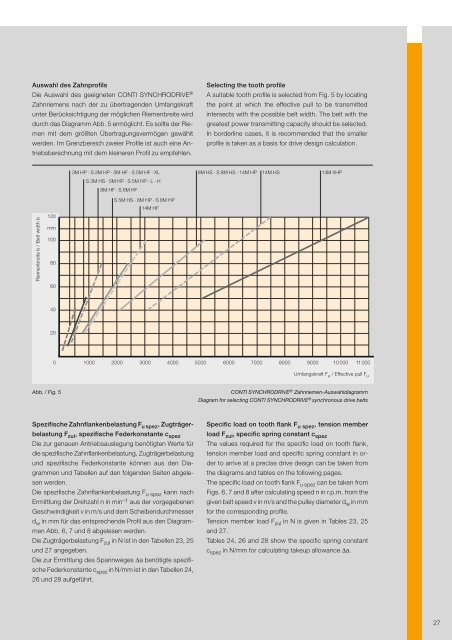
Auswahl des Zahnprofils<br />
Die Auswahl des geeigneten <strong>CONTI</strong> SYNCHRODRIVE ®<br />
<strong>Zahnriemen</strong>s nach der zu übertragenden Umfangskraft<br />
unter Berücksichtigung der möglichen Riemenbreite wird<br />
durch das Diagramm Abb. 5 ermöglicht. Es sollte der Riemen<br />
mit dem größten Übertragungsvermögen gewählt<br />
werden. Im Grenzbereich zweier Profile ist auch eine Antriebsberechnung<br />
mit dem kleineren Profil zu empfehlen.<br />
Selecting the tooth profile<br />
A suitable tooth profile is selected from Fig. 5 by locating<br />
the point at which the effective pull to be transmitted<br />
intersects with the possible belt width. The belt with the<br />
greatest power transmitting capacity should be selected.<br />
In borderline cases, it is recommended that the smaller<br />
profile is taken as a basis for drive design calculation.<br />
3M HP · S 3M HP · 5M HF · S 5M HF · XL<br />
8M HS · S 8M HS · 14M HP<br />
14M HS<br />
14M XHP<br />
S 3M HS · 5M HP · S 5M HP · L · H<br />
8M HF · S 8M HF<br />
Riemenbreite b / Belt width b<br />
120<br />
mm<br />
100<br />
80<br />
60<br />
S 5M HS · 8M HP · S 8M HP<br />
14M HF<br />
40<br />
20<br />
0<br />
1000 2000 3000 4000 5000 6000 7000 8000 9000 10 000 11 000<br />
Umfangskraft F u / Effective pull F u<br />
Abb, / Fig. 5<br />
<strong>CONTI</strong> SYNCHRODRIVE ® <strong>Zahnriemen</strong>-Auswahldiagramm<br />
Diagram for selecting <strong>CONTI</strong> SYNCHRODRIVE ® synchronous drive belts<br />
Spezifische Zahnflankenbelastung F u spez , Zugträgerbelastung<br />
F zul , spezifische Federkonstante c spez<br />
Die zur genauen Antriebsauslegung benötigten Werte für<br />
die spezifische Zahnflankenbelastung, Zugträgerbelastung<br />
und spezifische Federkonstante können aus den Diagrammen<br />
und Tabellen auf den folgenden Seiten abgelesen<br />
werden.<br />
Die spezifische Zahnflankenbelastung F u spez kann nach<br />
Ermittlung der Drehzahl n in min –1 aus der vorgegebenen<br />
Geschwindigkeit v in m/s und dem Scheibendurchmesser<br />
d w in mm für das entsprechende Profil aus den Diagrammen<br />
Abb. 6, 7 und 8 abgelesen werden.<br />
Die Zugträgerbelastung F zul in N ist in den Tabellen 23, 25<br />
und 27 angegeben.<br />
Die zur Ermittlung des Spannweges Δa benötigte spezifische<br />
Federkonstante c spez in N/mm ist in den Tabellen 24,<br />
26 und 28 aufgeführt.<br />
Specific load on tooth flank F u spez , tension member<br />
load F zul , specific spring constant c spez<br />
The values required for the specific load on tooth flank,<br />
tension member load and specific spring constant in order<br />
to arrive at a precise drive design can be taken from<br />
the diagrams and tables on the following pages.<br />
The specific load on tooth flank F u spez can be taken from<br />
Figs. 6, 7 and 8 after calculating speed n in r.p.m. from the<br />
given belt speed v in m/s and the pulley diameter d w in mm<br />
for the corresponding profile.<br />
Tension member load F zul in N is given in Tables 23, 25<br />
and 27.<br />
Tables 24, 26 and 28 show the specific spring constant<br />
c spez in N/mm for calculating takeup allowance Δa.<br />
27