Biscuit Joiner - Triton Tools
Biscuit Joiner - Triton Tools
Biscuit Joiner - Triton Tools

You also want an ePaper? Increase the reach of your titles
YUMPU automatically turns print PDFs into web optimized ePapers that Google loves.
GB<br />
ASSEMBLY<br />
Step 1:<br />
Fit the Outer Bearings (H) to the Sliding Insert (A)<br />
using the M6 x 20 Screws (I) and M6 Hex Nuts<br />
(J) as shown. Ensure they are fitted on the same<br />
side of the slider as the three small holes. Fit the<br />
Inner Bearings (K) to the Sliding Insert using the<br />
M6 x 45 Screws (L) and M6 Flange Nuts (M). Do<br />
not completely tighten at this stage. All bearings<br />
should be parallel to the sides of the sliding<br />
insert.<br />
Fit the Bosses (O) from beneath the two central<br />
holes in the sliding insert and attach the Main<br />
Body (B) to the sliding insert by tightening the<br />
M6 x 30 Hex Bolts (P) and Washers (Q) through<br />
the captive nuts in the main body.<br />
Loosen off the depth stop screws on the<br />
underneath of the sliding insert to allow<br />
approximately 29mm movement of the springloaded<br />
plunger. (Fig.4)<br />
Step 2:<br />
Slide the zinc locking pin on the underside of the<br />
main body to the central 'lock' position.<br />
Fit the sliding insert into the router table tracks<br />
by locating the slots on the inner bearings onto<br />
the flange on the aluminium inner track. Now<br />
firmly tighten the inner bearing screws and<br />
check that the sliding insert slides smoothly. If<br />
there is any float between the aluminium inner<br />
track and the inner bearings, loosen the screws,<br />
twist the bearing slightly and re-tighten.<br />
The lock pin on the main body should locate<br />
in the slot on the router plate. In use: When<br />
a safety guard is depressed the lock pin is<br />
released, allowing the fence to slide in the<br />
direction the guard is depressed. The fence will<br />
automatically spring back to its central position.<br />
Note: If the fence does not freely spring back,<br />
loosen the fit of the inner bearings against the<br />
aluminium track, or spray the track with spray<br />
lubricant.<br />
Screw the Inner Clamp Knobs (N) onto the inner<br />
bearing screws (they cut their own thread).<br />
In use: When fitting or removing the sliding<br />
insert the cut-away edges of the clamps must<br />
face toward the inner track. During operation<br />
turn the cut-away edges away from the inner<br />
track. Do not over-tighten, the sliding insert<br />
should be held down free to slide.<br />
Check that the biscuit joiner is level with, or<br />
slightly above, the table surface and if necessary<br />
to remove it and adjust the height of the<br />
aluminum inner track on the router table.<br />
Step 3:<br />
Remove the <strong>Biscuit</strong> <strong>Joiner</strong> Cutter (C) from its<br />
storage position in the end of the main body.<br />
If you have a 1 ⁄4" router, remove the 1 ⁄4" Shank<br />
(D) from its storage position in the end of the<br />
main body. If tight, gently prise it out using a<br />
screwdriver. Unbolt the cutting disc from the 1 ⁄2"<br />
shank and refit it to the 1 ⁄4" shank. Do not overtighten.<br />
Store the unused 1 ⁄2" shank in place of<br />
the 1 ⁄4" shank in the end of the main body.<br />
Remove the biscuit joiner from the table. Fit the<br />
large insert ring, supplied with the router table,<br />
to the router plate. Tighten the cutter firmly into<br />
the router collet.<br />
Adjust the cutter height so that there is 5-7mm<br />
clearance between the underside of the cutter<br />
and the router plate. Make sure the router's<br />
height adjustment is securely locked before use.<br />
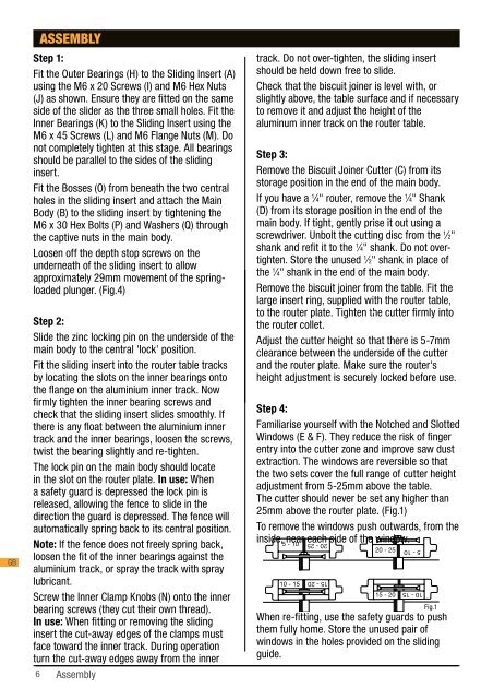
Step 4:<br />
Familiarise yourself with the Notched and Slotted<br />
Windows (E & F). They reduce the risk of finger<br />
entry into the cutter zone and improve saw dust<br />
extraction. The windows are reversible so that<br />
the two sets cover the full range of cutter height<br />
adjustment from 5-25mm above the table.<br />
The cutter should never be set any higher than<br />
25mm above the router plate. (Fig.1)<br />
To remove the windows push outwards, from the<br />
inside, near each side of the window.<br />
5 - 10<br />
10 - 15<br />
20 - 25<br />
15 - 20<br />
20 - 25<br />
15 - 20<br />
5 - 10<br />
10 - 15<br />
Fig.1<br />
When re-fitting, use the safety guards to push<br />
them fully home. Store the unused pair of<br />
windows in the holes provided on the sliding<br />
guide.<br />
For the next few steps, fit the notched windows<br />
(with the '5-10' designation reading right way up)<br />
to both sides of the main body by inserting them<br />
into slots beside each window opening. Use the<br />
safety guards to push them fully home. (Fig.2)<br />
Step 5:<br />
Fit the biscuit joiner back onto the table.<br />
With the power cord disconnected, push in the<br />
safety guards and check that the cutter clears<br />
the guards and the plastic windows.<br />
At full extension the cutter should protrude<br />
13mm from the face of each window (Fig.3). Use<br />
a screwdriver to adjust the depth stop screws<br />
on the underside of the sliding insert, inward or<br />
outward, until 13mm is achieved (Fig.4). In use:<br />
You can adjust the stops to limit the travel for<br />
shallower slots in thin material, using cut down<br />
biscuits.<br />
Step 6:<br />
Fit the Sliding Guide Clamp (R) to the Sliding<br />
Guide (G), using a Coach Bolt (S) and Round Knob<br />
(T).<br />
With the knob loosened, you can slide the guide<br />
on and off the main body. Tightening the knob<br />
locks the guide to the main body (Fig.5)<br />
Dust Extraction<br />
The biscuit joiner has been designed for use with<br />
a vacuum cleaner for sawdust extraction. It can<br />
be used without dust extraction, but you will need<br />
to lift the main body after every 20-30 cuts to<br />
clean out accumulated shavings.<br />
While any vacuum cleaner can be used, domestic<br />
(bag-type) units can fill up very quickly. For a<br />
much larger capacity, we recommend fitting a<br />
<strong>Triton</strong> Dust Collector (DCA300) to your vacuum<br />
cleaner.<br />
Screw the vacuum hose (left-hand thread),<br />
supplied with your router table, onto the dust port<br />
at the end of the main body and plug the wand of<br />
your vacuum cleaner into the hose adaptor.<br />
Power Connection Warning<br />
The combined electrical load of your router and<br />
vacuum cleaner may exceed the rated amperage<br />
of your domestic extension lead or power outlet.<br />
Therefore you should connect your vacuum<br />
cleaner and router to separate outlets, and switch<br />
on both appliances separately.<br />
Safety<br />
• Always work in a well lit, uncluttered<br />
environment.<br />
• Always wear safety glasses and hearing<br />
protection.<br />
• Make sure the Router Table is securely locked<br />
down to your Workcentre or Router Stand.<br />
• Always switch off the power and/or disconnect<br />
the power cord when fitting or adjusting the<br />
cutter or raising the main body.<br />
• Always keep hands clear of the cutter<br />
apertures in the main body and never operate<br />
6 Assembly<br />
Assembly 7<br />
Fig.2<br />
Fig.3<br />
Fig.4<br />
Fig.5<br />
GB